JP2005291667A - Gas cookstove - Google Patents
Gas cookstove Download PDFInfo
- Publication number
- JP2005291667A JP2005291667A JP2004110718A JP2004110718A JP2005291667A JP 2005291667 A JP2005291667 A JP 2005291667A JP 2004110718 A JP2004110718 A JP 2004110718A JP 2004110718 A JP2004110718 A JP 2004110718A JP 2005291667 A JP2005291667 A JP 2005291667A
- Authority
- JP
- Japan
- Prior art keywords
- burner
- gas
- combustion
- exhaust
- combustion chamber
- Prior art date
- Legal status (The legal status is an assumption and is not a legal conclusion. Google has not performed a legal analysis and makes no representation as to the accuracy of the status listed.)
- Pending
Links
Images
Landscapes
- Gas Burners (AREA)
Abstract
Description
本発明は、ガスコンロ、特に、前記ガスバーナの燃焼に伴うの燃焼排気で鍋底を加熱する形式のガスバーナを具備するガスコンロに関するものである。 The present invention relates to a gas stove, and more particularly to a gas stove including a gas burner of a type in which the bottom of a pan is heated by combustion exhaust gas accompanying combustion of the gas burner.
天板(1)に円形のバーナ用開口(10)が形成され、前記開口(10)の下方に、燃焼室(20)が設けられ、前記燃焼室(20)から排出される燃焼排気で鍋(44)を加熱する形式のガスバーナを具備するガスコンロとして、図5に示すものがある。
このガスコンロに使用されているガスバーナ(3)は、上流端に燃料ガス供給用のノズル(図示せず)が差し込まれるガス供給口(38)を具備するベンチュリ(36)と、前記ベンチュリ(36)の下流側で且つ前記燃焼室(20)の下方に配設されるバーナボディ(30)とからなり、前記バーナボディ(30)の上端に形成された炎孔(35)からの燃焼ガスが燃焼することによって、燃焼室(20)内に燃焼部が形成される。
尚、前記燃焼室(20)は、上方の前記バーナ用開口(10)側及び下方の燃焼部側に開放する包囲筒(26)によって包囲されており、前記包囲筒(26)の上方は、五徳兼用カバー(4)で閉塞されている。
A circular burner opening (10) is formed in the top plate (1), a combustion chamber (20) is provided below the opening (10), and the pan is made of combustion exhaust discharged from the combustion chamber (20). FIG. 5 shows a gas stove having a gas burner of the type for heating (44).
The gas burner (3) used in the gas stove includes a venturi (36) having a gas supply port (38) into which a fuel gas supply nozzle (not shown) is inserted at the upstream end, and the venturi (36). The combustion gas from the flame hole (35) formed at the upper end of the burner body (30) is combusted on the downstream side of the combustion chamber (20) and below the combustion chamber (20). By doing so, a combustion part is formed in the combustion chamber (20).
The combustion chamber (20) is surrounded by a surrounding cylinder (26) opened to the upper burner opening (10) side and the lower combustion part side, and the upper side of the surrounding cylinder (26) is It is closed with a virtually combined cover (4).
前記五徳兼用カバー(4)は、上面に、放射状に延びる複数の鍋載置リブ(42)が隆起していると共に、前記鍋載置リブ(42)の側面に、前記燃焼室(20)に連通する排気口(40a)(40b)が開設されている。前記燃焼室(20)内で生成される燃焼排気は、前記排気口(40a)(40b)から天板(1)の上方へ排出され、前記五徳兼用カバー(4)の鍋載置リブ(42)上に載置されている鍋(44)の底を加熱する。
ガスコンロは、燃焼排気を鍋(44)の底に接触させて加熱するものであるが、上記従来のガスコンロでは、鍋載置リブ(42)の外側寄りに開設されている前記排気孔(40b)から排出される燃焼排気は、鍋(44)の底の外周縁近傍しか加熱することができず、鍋底の中央の排気孔(40a)から外周縁に向かって排出される燃焼排気に比べて熱効率が不十分であるという問題がある。
本発明は、かかる点に鑑みてなされたものであり、『天板に開設されたバーナ用開口の下方にガスバーナを燃焼させる燃焼室が設けられ、前記ガスバーナの燃焼によって前記燃焼室内で生成された燃焼排気を前記バーナ用開口から排出させると共に、前記排出された燃焼排気によって、前記バーナ用開口の上方に載置されている鍋を加熱する形式のガスコンロ』において、高い熱効率を得るために、前記燃焼室内の燃焼排気を前記バーナ用開口の中央に集めて天板の上方に円滑に排出できるようにすることを課題とする。
The gas stove heats the combustion exhaust by bringing it into contact with the bottom of the pan (44) .In the conventional gas stove, the exhaust hole (40b) opened near the outside of the pan mounting rib (42). The combustion exhaust discharged from the bottom can only be heated near the outer peripheral edge of the bottom of the pan (44), and is more efficient than the combustion exhaust discharged from the central exhaust hole (40a) of the pan bottom toward the outer peripheral edge. There is a problem that is insufficient.
The present invention has been made in view of such a point, and “a combustion chamber for burning a gas burner is provided below a burner opening formed in a top plate, and the combustion chamber is generated in the combustion chamber by combustion of the gas burner. In order to obtain high thermal efficiency in a gas stove that exhausts combustion exhaust from the burner opening and heats the pan placed above the burner opening by the discharged combustion exhaust, It is an object of the present invention to collect the combustion exhaust in the combustion chamber at the center of the burner opening so that it can be smoothly discharged above the top plate.
[請求項1に係る発明]
上記課題を解決する為の請求項1に係る発明の技術的手段は、『前記ガスバーナは、環状に構成されたバーナボディを具備し、
前記バーナボディの内側周面で包囲された内側空間内に、前記燃焼室が上方にのみ開放するように設けられ、
前記燃焼室の底部中央に排気筒が直立姿勢に配設され、
前記バーナボディの前記内側周面に複数の炎孔が開設されていると共に、前記炎孔よりも低い位置に対応する前記排気筒の周壁に複数の開口が開設されている』ことである。
上記技術的手段は次のように作用する。
ガスバーナを燃焼させると、炎孔から燃焼ガスが、バーナボディの内側空間の燃焼室内に燃焼排気が噴き出される。燃焼室は上方にのみ開放しており、その底部中央には、排気筒が上方開放状態に直立している。前記排気筒の周壁の、前記炎孔より低い部分に開口は形成されているから、前記炎孔から噴出された燃焼排気は、前記排気筒の周壁のうち、前記開口が形成されていない部分に衝突し、上方及び下方に向きを変える。上方に向かう燃焼排気は前記周壁の外周面に沿って上昇し、前記バーナ用開口から天板の上方に排出される。下方へ向かった燃焼排気は、前記排気筒の周壁の、前記炎孔よりも低い位置に開設されている開口から排気筒内に送り込まれ、前記排気筒内で上方に向きを変えて、前記排気筒内を通ってその上方から排出されていく。このように、燃焼室内に噴出された燃焼排気は、排気筒の外周面に沿って又は排気筒内を通って、バーナ用開口の中央近傍に集中して排出されていく。
[Invention of Claim 1]
The technical means of the invention according to claim 1 for solving the above-mentioned problem is as follows: "The gas burner comprises a burner body configured in an annular shape,
In the inner space surrounded by the inner peripheral surface of the burner body, the combustion chamber is provided so as to open only upward,
An exhaust pipe is disposed in an upright posture at the center of the bottom of the combustion chamber,
A plurality of flame holes are formed in the inner peripheral surface of the burner body, and a plurality of openings are formed in the peripheral wall of the exhaust pipe corresponding to a position lower than the flame holes.
The technical means operates as follows.
When the gas burner is burned, the combustion gas is ejected from the flame hole and the combustion exhaust gas is ejected into the combustion chamber in the inner space of the burner body. The combustion chamber is open only upward, and an exhaust pipe stands upright in the center of the bottom. Since the opening is formed in the lower part of the peripheral wall of the exhaust pipe than the flame hole, the combustion exhaust ejected from the flame hole is in the part of the peripheral wall of the exhaust pipe where the opening is not formed. Collide and turn up and down. The upward combustion exhaust gas rises along the outer peripheral surface of the peripheral wall, and is discharged from the burner opening above the top plate. Combustion exhaust that is directed downward is sent into the exhaust pipe through an opening of the peripheral wall of the exhaust pipe that is lower than the flame hole, and is turned upward in the exhaust pipe to change the exhaust gas. It is discharged from above through the cylinder. Thus, the combustion exhaust sprayed into the combustion chamber is exhausted in the vicinity of the center of the burner opening along the outer peripheral surface of the exhaust pipe or through the exhaust pipe.
[請求項2に係る発明]
請求項1に係る発明において、『前記炎孔は、前記内側空間の中心に対して所定角度傾斜した方向に貫通形成されている』ものでは、バーナボディの内側空間の中心に対して傾斜した方向に噴出される燃焼ガスは、燃焼室内を旋回する。前記燃焼排気は前記排気筒の周壁の外周面に沿って旋回しながら、上方及び下方へ流れていき、下方へ向かった燃焼排気は、前記開口から前記排気筒内に入り込み、前記排気筒内を旋回しながら上昇していく。
[Invention of Claim 2]
In the invention according to claim 1, in the case where “the flame hole is formed to penetrate in a direction inclined at a predetermined angle with respect to the center of the inner space”, the direction inclined with respect to the center of the inner space of the burner body. The combustion gas ejected to the inside swirls in the combustion chamber. The combustion exhaust gas flows upward and downward while swirling along the outer peripheral surface of the peripheral wall of the exhaust pipe. Combustion exhaust gas directed downward enters the exhaust pipe through the opening and passes through the exhaust pipe. Ascending while turning.
[請求項3に係る発明]
請求項1又は2に係る発明において、『前記燃焼室の底部は、断熱材によって閉塞されており、前記断熱材の中央上面に前記排気筒を固定した』ものでは、ガスバーナの燃焼時には燃焼室内は高温になるが、底部に断熱材が設けられていることから、燃焼室内の熱が外部に漏れ難くなる。又、前記排気筒は、前記断熱材の中央部分に固定されているから、配設状態が安定する。
[Invention of Claim 3]
In the invention according to claim 1 or 2, "the bottom of the combustion chamber is closed by a heat insulating material, and the exhaust pipe is fixed to a central upper surface of the heat insulating material", the combustion chamber is Although it becomes high temperature, since the heat insulating material is provided at the bottom, the heat in the combustion chamber hardly leaks to the outside. Moreover, since the exhaust pipe is fixed to the central portion of the heat insulating material, the arrangement state is stabilized.
[請求項4に係る発明]
上記各請求項に係る発明において、『前記バーナ用開口は、上面に複数の鍋支持用突起が突設し且つ前記鍋支持用突起の形成域よりも内側の中央部分に排気孔が貫通形成されている五徳兼用カバーで被覆されており、前記排気筒の直径を、前記中央部分の直径に略一致させた』ものでは、前記中央部分に排気孔が設けられ、それよりも外側に複数の鍋支持用突起が突設する形式の五徳兼用カバーを設ける構成としたもので、前記排気筒の直径を、五徳兼用カバーの前記中央部分の直径に略一致させていることから、燃焼室の中央に設けた排気筒の外周面に沿って又はその内部を通ってバーナ用開口の中央付近に集められた燃焼室内の燃焼排気は、ちょうど、五徳兼用カバーの前記中央部分に対応し、排気孔から効率良く排出されていく。
[Invention of Claim 4]
In the invention according to each of the above claims, “the burner opening has a plurality of pan support protrusions projecting from an upper surface thereof and an exhaust hole penetratingly formed in a central portion inside the formation area of the pan support protrusions. Is covered with a virtually combined cover, and the diameter of the exhaust tube is substantially the same as the diameter of the central portion ”, an exhaust hole is provided in the central portion, and a plurality of pans are provided on the outer side. It is configured to provide a virtually combined cover of a type in which a supporting protrusion protrudes, and the diameter of the exhaust pipe is substantially matched with the diameter of the central portion of the virtually combined cover. Combustion exhaust in the combustion chamber collected near the center of the burner opening along the outer peripheral surface of the provided exhaust pipe or through the inside thereof corresponds to the central portion of the virtually combined cover, and is efficient from the exhaust hole. It is discharged well.
本願発明は次の特有の効果を有する。
燃焼室内の中央に排気筒を設けることにより、燃焼室内の燃焼排気はバーナ用開口の中央に集められた状態で排出されることから、バーナボディの上方に設けられる鍋の底の中央部分を集中的に加熱することができる。これにより、熱交換率の良いガスコンロを提供することができる。又、下方に向かう燃焼排気は排気筒の中を通って、天板上方へ排出されるため、排気抵抗が小さくなり、燃焼が安定する。
The present invention has the following specific effects.
By providing an exhaust tube in the center of the combustion chamber, the combustion exhaust in the combustion chamber is discharged in the state of being collected at the center of the burner opening, so the central portion of the bottom of the pan provided above the burner body is concentrated. Can be heated. Thereby, the gas stove with a good heat exchange rate can be provided. Further, since the downward combustion exhaust gas passes through the exhaust pipe and is discharged to the upper side of the top plate, the exhaust resistance is reduced and the combustion is stabilized.
請求項2に係る発明では、上記効果に加えて、炎孔から噴出される燃焼ガスは、排気筒の回りを旋回するため、下方に向かう燃焼排気を排気筒の開口から取り込み易い。又、燃焼排気は旋回しながらバーナ用開口の中央部分へ向かって上昇するから、燃焼排気の衝突が減少して排気抵抗が小さくなり、バーナ用開口から天板の上方へ排出され易くなる。よって、燃焼排気は、効率良くバーナ用開口から排出され、燃焼が安定する。 In the invention according to claim 2, in addition to the above-described effect, the combustion gas ejected from the flame hole swirls around the exhaust pipe, so that it is easy to take in the downward combustion exhaust gas from the opening of the exhaust pipe. Further, since the combustion exhaust rises toward the center portion of the burner opening while turning, the collision of the combustion exhaust is reduced, the exhaust resistance is reduced, and the combustion exhaust is easily discharged upward from the top plate. Therefore, the combustion exhaust is efficiently discharged from the burner opening, and the combustion is stabilized.
請求項3に係る発明によれば、燃焼室の底部に設けた断熱材によって、燃焼室内の熱が外部に漏れ難いようにしたから、ガスコンロ内に配設された電気制御装置等への熱的悪影響を防止することができる。又、排気筒を燃焼室の中央に容易に固定することができる効果がある。 According to the third aspect of the present invention, the heat insulating material provided at the bottom of the combustion chamber makes it difficult for the heat in the combustion chamber to leak to the outside, so that the heat to the electric control device or the like disposed in the gas stove is reduced. Adverse effects can be prevented. Further, there is an effect that the exhaust pipe can be easily fixed at the center of the combustion chamber.
請求項4に係る発明によれば、五徳兼用カバーの中央部分に燃焼排気を集中させるようにしたから、主に中央部分に排気孔が形成された構成の五徳兼用カバーを採用しても、燃焼排気は円滑に排出され、さらに、高い熱効率を得ることが可能となる。又、天板の上面を凹凸の少ないすっきりしたデザインに仕上げることができ、薄型で且つ手入れの簡単なガスコンロを提供することができる。 According to the invention of claim 4, since the combustion exhaust is concentrated on the central portion of the virtually combined cover, even if the virtually combined cover having an exhaust hole formed mainly in the central portion is employed, Exhaust gas is discharged smoothly, and high thermal efficiency can be obtained. Further, the top surface of the top plate can be finished in a clean design with little unevenness, and a gas stove that is thin and easy to maintain can be provided.
以下に、本発明を実施するための最良の形態について添付図面を参照しながら説明する。
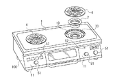
図1に示すように、扁平な矩形箱状に形成されたケーシング(100)の天板(1)にはバーナ用開口(10)が開設されており、前記バーナ用開口(10)は五徳兼用カバー(4)で被覆されると共に、その下方には、ガスバーナ(33)が配設される。又、ケーシング(100)の前面の操作部(11)には、ガスバーナ(33)に点火・消火する際に押し込み操作し、且つ、火力調節の際には回転操作する操作つまみ(51)と、ガスバーナ(33)が燃焼状態にあることを報知する燃焼ランプ(52)が配設されている。
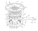
特に、この実施の形態のガスバーナ(33)は、図2に示すように、燃料ガス供給用のガスノズル(19)が差し込まれる上流端のガス入口(34)を備えたベンチュリ(36)と、該ベンチュリ(36)の下流端に連設され且つ内側空間(32)を有するように環状に形成されているバーナボディ(31)とから構成されており、前記ベンチュリ(36)内で、燃料ガスと一次空気が混合されて前記バーナボディ(31)に送られる。
The best mode for carrying out the present invention will be described below with reference to the accompanying drawings.
As shown in FIG. 1, the top plate (1) of the casing (100) formed in the shape of a flat rectangular box is provided with a burner opening (10). While being covered with the cover (4), a gas burner (33) is disposed below the cover (4). Further, an operation knob (51) that is pushed in when the gas burner (33) is ignited and extinguished, and is rotated when adjusting the heating power, in the operation part (11) on the front surface of the casing (100), A combustion lamp (52) for notifying that the gas burner (33) is in a combustion state is provided.
In particular, the gas burner (33) of this embodiment comprises a venturi (36) having an upstream gas inlet (34) into which a gas nozzle (19) for fuel gas supply is inserted, as shown in FIG. A burner body (31) connected to the downstream end of the venturi (36) and formed in an annular shape so as to have an inner space (32) .In the venturi (36), fuel gas and Primary air is mixed and sent to the burner body (31).
前記バーナボディ(31)の内側周面(31a)には、多数の縦長長方形状の筒状部(37)が前記内側空間(32)に向かって突出しており、前記筒状部(37)の軸線に沿って、貫通するように炎孔(35)が形成されている。すなわち、前記筒状部(37)の突出端に、前記炎孔(35)が開放している。
そして、前記筒状部(37)の突出端で囲まれる前記内側空間(32)内に金属製のガイド筒(2)が収容される。
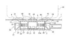
尚、ガイド筒(2)の下端には、図4に示すように、ガラスウールやセラミック等の断熱材(23)が嵌め込まれ、これにより、バーナボディ(31)内には、周囲がガイド筒(2)で囲まれ且つ底部に断熱材(23)が配設された空間が構成され、この空間が燃焼室(20)として機能する。
On the inner peripheral surface (31a) of the burner body (31), a large number of vertically-long rectangular cylindrical portions (37) protrude toward the inner space (32), and the cylindrical portion (37) A flame hole (35) is formed so as to penetrate along the axis. That is, the flame hole (35) is opened at the projecting end of the cylindrical portion (37).
A metal guide tube (2) is housed in the inner space (32) surrounded by the protruding end of the tubular portion (37).
As shown in FIG. 4, a heat insulating material (23) such as glass wool or ceramic is fitted into the lower end of the guide tube (2), so that the periphery of the guide tube (2) is surrounded by the guide tube. A space surrounded by (2) and provided with a heat insulating material (23) at the bottom is formed, and this space functions as a combustion chamber (20).
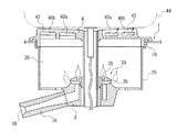
そして、前記断熱材(23)の中央部分に、環状の溝部(23a)を同心状に設け、この溝部(23a)に、図3に示すような、金属製の排気筒(21)の下端部を差し込んで固定する。これにより、前記排気筒(21)は、図2及び図4に示すように、上方に開放する態様で、燃焼室(20)(ガイド筒(2))内の中央に固定されることとなる。
前記筒状部(37)は、内側空間(32)の中心に対して約30度傾斜させた姿勢で水平に突出するように設けられている。これにより、前記筒状部(37)に設けられた前記炎孔(35)からの燃焼ガスは、内側空間(32)の中心より約30度ずれた方向に噴出される。
An annular groove (23a) is provided concentrically in the central portion of the heat insulating material (23), and the lower end of a metal exhaust pipe (21) as shown in FIG. 3 is provided in the groove (23a). Insert and fix. Thereby, as shown in FIG.2 and FIG.4, the said exhaust pipe (21) will be fixed to the center in a combustion chamber (20) (guide pipe | tube (2)) in the aspect open | released upwards. .
The tubular portion (37) is provided so as to protrude horizontally in a posture inclined about 30 degrees with respect to the center of the inner space (32). Thereby, the combustion gas from the flame hole (35) provided in the cylindrical part (37) is ejected in a direction shifted by about 30 degrees from the center of the inner space (32).
前記ガイド筒(2)は、前記天板(1)に形成されたバーナ用開口(10)の周縁部に係止させるための上端フランジ(24)を具備していると共に、前記ガスバーナ(33)の筒状部(37)の突出端に対応する前記ガイド筒(2)の周壁の各位置には、前記突出端よりも一回り大きな縦長長方形状の窓部(27)が形成されている。
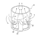
又、前記排気筒(21)には、前記炎孔(35)の開口位置よりも低い位置に、複数の比較的大きな開口(22)が形成されている。前記排気筒(21)の下端縁を前記断熱材(23)の溝部(23a)に差し込んだ配設状態においては、前記開口(22)は、前記断熱材(23)の上面に近接して位置する態様となる。
The guide tube (2) includes an upper end flange (24) for engaging with a peripheral edge of a burner opening (10) formed in the top plate (1), and the gas burner (33). At each position of the peripheral wall of the guide tube (2) corresponding to the protruding end of the cylindrical portion (37), a vertically long rectangular window portion (27) that is slightly larger than the protruding end is formed.
In addition, a plurality of relatively large openings (22) are formed in the exhaust pipe (21) at a position lower than the opening position of the flame hole (35). In the arrangement state in which the lower end edge of the exhaust pipe (21) is inserted into the groove (23a) of the heat insulating material (23), the opening (22) is positioned close to the upper surface of the heat insulating material (23). It becomes the mode to do.
そして、バーナ用開口(10)の周縁に係止させた前記上端フランジ(24)の上面に、赤熱プレート(5)を介して、五徳兼用カバー(4)を被蓋配設させて、ガスコンロが完成する。尚、前記排気筒(21)の高さは、断熱材(23)に設置した状態で、前記赤熱プレート(5)の下面に近接するように設定されている。
上記五徳兼用カバー(4)は、前記バーナ用開口(10)を閉塞可能な大きさの熱伝導性の良好な金属材料で形成された円盤であり、図2に示すように、中央部分に貫設された排気孔(40)と、その外周域に、鍋(44)を載置させるための複数の鍋支持用突起(41)が周方向に所定ピッチで放射状に配設されている。
Then, on the upper surface of the upper end flange (24) locked to the peripheral edge of the burner opening (10), the virtuosity cover (4) is covered with a red hot plate (5), and the gas stove is attached. Complete. The height of the exhaust pipe (21) is set so as to be close to the lower surface of the red hot plate (5) in a state where it is installed on the heat insulating material (23).
The virtually combined cover (4) is a disk made of a metal material having a good thermal conductivity that is large enough to close the burner opening (10). As shown in FIG. The provided exhaust holes (40) and a plurality of pan support projections (41) for placing the pans (44) are radially arranged at a predetermined pitch in the circumferential direction in the outer peripheral area.
又、バーナボディ(31)の下部内周は、図4に示すように、下方に向かって直径が拡大する環状テーパー部(39)となっており、これにより、該環状テーパー部(39)に沿って二次空気が、前記バーナボディ(31)の内側周面(31a)とガイド筒(2)の外周面との間の隙間へ導入させ易くなっている。尚、前記バーナボディ(31)の上方と天板(1)との間にも空間(13)が形成されており、前記環状テーパー部(39)近傍の空間及び空間(13)から、バーナボディ(31)とガイド筒(2)との前記隙間に繋がる通路が、筒状部(37)への燃焼用の二次空気供給通路として機能することとなる。 Further, as shown in FIG. 4, the lower inner periphery of the burner body (31) has an annular taper portion (39) whose diameter increases downward, and thereby the annular taper portion (39) The secondary air is easily introduced along the gap between the inner peripheral surface (31a) of the burner body (31) and the outer peripheral surface of the guide tube (2). A space (13) is also formed between the top of the burner body (31) and the top plate (1), and from the space and space (13) in the vicinity of the annular tapered portion (39), the burner body The passage connecting the gap between (31) and the guide tube (2) functions as a secondary air supply passage for combustion to the tubular portion (37).
次に、上記ガスコンロの使用の実際を説明する。
図1に表れる特定の操作つまみ(51)を押し込むと、点火装置(図示せず)が作動してガスバーナ(33)の炎孔(35)に点火用スパークが連射される。
又、上記操作つまみ(51)が押し込まれると、ガスバーナ(33)へのガス回路に挿入されたガス弁が開弁してガスノズル(19)からベンチュリ(36)のガス入口(34)内に燃料ガスが噴出されると共に、噴出時のエゼクタ効果によって、ガスノズル(19)の周囲の空気が燃焼用一次空気としてガス入口(34)内に誘引され、これにより、一次空気が混合された燃焼ガスがガスバーナ(33)のバーナボディ(31)に送られ、筒状部(37)を通って炎孔(35)から噴出する。
Next, the actual use of the gas stove will be described.
When a specific operation knob (51) shown in FIG. 1 is pushed in, an ignition device (not shown) is activated to ignite an ignition spark in the flame hole (35) of the gas burner (33).
When the operation knob (51) is pushed in, the gas valve inserted in the gas circuit to the gas burner (33) is opened, and the fuel from the gas nozzle (19) to the gas inlet (34) of the venturi (36) is opened. As the gas is ejected and the ejector effect at the time of ejection, the air around the gas nozzle (19) is attracted into the gas inlet (34) as primary combustion air, so that the combustion gas mixed with the primary air is It is sent to the burner body (31) of the gas burner (33), and ejects from the flame hole (35) through the cylindrical part (37).
筒状部(37)は、上記したように傾斜姿勢にあることから、炎孔(35)から噴出される燃焼ガスは、窓部(27)を介して、前記ガイド筒(2)内に、中心よりも約30度外れた方向に向かって噴き出すこととなる。
前記炎孔(35)から噴出される燃焼ガスに、前記二次空気供給通路から炎孔(35)に供給される二次空気が混合され、二次空気が混合された燃焼ガスに、上記点火装置から点火されてこれが燃焼し、筒状部(37)の突出端に燃焼炎が形成される。このときに生成される燃焼排気は、前記ガイド筒(2)内で、前記排気筒(21)の周壁のうち、開口(22)が形成されていない部分の周りを旋回する旋回流となる。
Since the cylindrical part (37) is in the inclined posture as described above, the combustion gas ejected from the flame hole (35) is passed through the window part (27) into the guide cylinder (2). It will be ejected in a direction about 30 degrees away from the center.
The combustion gas ejected from the flame hole (35) is mixed with the secondary air supplied from the secondary air supply passage to the flame hole (35), and the combustion gas mixed with the secondary air is ignited. It is ignited from the apparatus and burns, and a combustion flame is formed at the projecting end of the cylindrical portion (37). The combustion exhaust generated at this time becomes a swirl flow swirling around a portion of the peripheral wall of the exhaust tube (21) where the opening (22) is not formed in the guide tube (2).
上記したように排気筒(21)の周囲を旋回する燃焼排気は、図3に示すように、旋回しながら上昇又は降下していく。上昇する燃焼排気は、前記排気筒(21)の外周面に沿って旋回していき前記赤熱プレート(5)を介して、五徳兼用カバー(4)の中央の排気孔(40)から排出される。降下する燃焼排気は、ガイド筒(2)の底部に嵌め込まれた断熱材(23)近傍に開口している排気筒(21)の開口(22)から、排気筒(21)内に送り込まれ、排気筒(21)内で上昇する方向へ向きを変えて、排気筒(21)の上方から排出されていく。
このように、燃焼室(20)内で生成された燃焼排気は、排気筒(21)の周囲を旋回し、その外周面に沿って、又は、排気筒(21)の内部を通って、バーナ用開口(10)の中央部分に集中させて排出されることとなる。よって、前記燃焼排気は、バーナ用開口(10)を閉塞している五徳兼用カバー(4)の中央部分の排気孔(40)から、天板(1)の上方に円滑に排出されていく。
As described above, the combustion exhaust swirling around the exhaust pipe (21) rises or descends while swirling as shown in FIG. The rising combustion exhaust gas swirls along the outer peripheral surface of the exhaust pipe (21), and is discharged from the central exhaust hole (40) of the virtually combined cover (4) through the red hot plate (5). . The descending combustion exhaust is sent into the exhaust pipe (21) from the opening (22) of the exhaust pipe (21) opened near the heat insulating material (23) fitted in the bottom part of the guide cylinder (2), The direction is changed in the direction of rising in the exhaust pipe (21), and the gas is discharged from above the exhaust pipe (21).
In this way, the combustion exhaust generated in the combustion chamber (20) swirls around the exhaust pipe (21) and passes along the outer peripheral surface or through the inside of the exhaust pipe (21) to burner. It will be discharged in a concentrated manner at the center of the opening (10). Therefore, the combustion exhaust gas is smoothly discharged above the top plate (1) from the exhaust hole (40) in the central portion of the virtually combined cover (4) closing the burner opening (10).
これにより、五徳兼用カバー(4)の鍋支持用突起(41)上に載置させた鍋(44)の底の中央部分に前記燃焼排気が集中的に噴き出すこととなり、鍋(44)は、前記中央部分から外周縁部にかけての広い範囲が前記燃焼排気の流れの接触範囲となり、効率良く加熱されることとなる。又、前記降下する燃焼排気は、排気筒(21)内を上昇して天板(1)の上方へ排出されるため、燃焼排気の排気抵抗は小さくなり、安定した燃焼を得ることができる。
又、上記燃焼排気によって、五徳兼用カバー(4)の下方の赤熱プレート(5)が赤熱され、該赤熱プレート(5)からの輻射熱が五徳兼用カバー(4)越しに鍋(44)に照射されることとなるから、前記輻射熱によっても鍋(44)が加熱される。
As a result, the combustion exhaust gas intensively spouts out to the central part of the bottom of the pan (44) placed on the pan support protrusion (41) of the virtually combined cover (4), and the pan (44) A wide range from the central portion to the outer peripheral edge portion becomes a contact range of the flow of the combustion exhaust gas, and is efficiently heated. Further, since the descending combustion exhaust gas rises in the exhaust pipe (21) and is discharged above the top plate (1), the exhaust resistance of the combustion exhaust gas becomes small and stable combustion can be obtained.
Also, by the combustion exhaust, the red hot plate (5) below the virtuosity cover (4) is red hot, and the radiant heat from the red hot plate (5) is irradiated to the pan (44) through the virtuosity cover (4). Therefore, the pan (44) is also heated by the radiant heat.
一方、ガスバーナ(33)の燃焼時にはガイド筒(2)内が高温になるが、前記ガイド筒(2)の底部には断熱材(23)が嵌め込まれているから、ガイド筒(2)内の熱がケーシング(100)内に漏れ難くなり、これにより、ケーシング(100)内に配設された電気制御装置等への熱的悪影響を防止することができる。 On the other hand, when the gas burner (33) burns, the inside of the guide cylinder (2) becomes hot, but since the heat insulating material (23) is fitted in the bottom of the guide cylinder (2), the inside of the guide cylinder (2) Heat is less likely to leak into the casing (100), thereby preventing adverse thermal effects on the electrical control device and the like disposed in the casing (100).
上記実施の形態ではバーナ用開口(10)を五徳兼用カバー(4)で覆ったが、天板(1)上のバーナ用開口(10)の外周域に五徳を載置するガスコンロとしても良い。
尚、上記実施の形態では、炎孔(35)の向きを中心方向に対して斜めに設定したが、中心に向けても良い。
又、上記実施の形態では、炎孔(35)の向きを水平に向けたが、斜め上方に向くように設定しても良い。
In the above embodiment, the burner opening (10) is covered with the virtuosity cover (4). However, a gas stove in which the virtues are placed on the outer peripheral area of the burner opening (10) on the top plate (1) may be used.
In the above embodiment, the direction of the flame hole (35) is set obliquely with respect to the central direction, but it may be directed toward the center.
In the above-described embodiment, the direction of the flame hole (35) is horizontally oriented, but may be set to be obliquely upward.
(1) ・・・・・・天板
(10)・・・・・・バーナ用開口
(20)・・・・・・燃焼室
(21)・・・・・・排気筒
(22)・・・・・・開口
(3) ・・・・・・ガスバーナ
(31)・・・・・・バーナボディ
(32)・・・・・・内側空間
(33)・・・・・・ガスバーナ
(35)・・・・・・炎孔
(44)・・・・・・鍋
(1) ...
(10) ... Burner opening
(20) ... combustion chamber
(21) ... Exhaust tube
(22) ... Opening
(3) ・ ・ ・ ・ ・ ・ Gas burner
(31) ... Burner body
(32) ... Inside space
(33) ... Gas burner
(35)
(44)
Claims (4)
前記ガスバーナは、環状に構成されたバーナボディを具備し、
前記バーナボディの内側周面で包囲された内側空間内に、前記燃焼室が上方にのみ開放するように設けられ、
前記燃焼室の底部中央に排気筒が直立姿勢に配設され、
前記バーナボディの前記内側周面に複数の炎孔が開設されていると共に、前記炎孔よりも低い位置に対応する前記排気筒の周壁に複数の開口が開設されていることを特徴とするガスコンロ。 A combustion chamber for burning the gas burner is provided below the burner opening established in the top plate, and the combustion exhaust generated in the combustion chamber by the combustion of the gas burner is discharged from the burner opening and the exhausted In a gas stove of the type that heats the pan placed above the burner opening by combustion exhaust,
The gas burner comprises a burner body configured in an annular shape,
In the inner space surrounded by the inner peripheral surface of the burner body, the combustion chamber is provided so as to open only upward,
An exhaust pipe is disposed in an upright posture at the center of the bottom of the combustion chamber,
A gas stove having a plurality of flame holes in the inner peripheral surface of the burner body and a plurality of openings in the peripheral wall of the exhaust tube corresponding to a position lower than the flame holes .
前記炎孔は、前記内側空間の中心に対して所定角度傾斜した方向に貫通形成されていることを特徴とするガスコンロ。 The gas stove according to claim 1, wherein
The gas stove characterized in that the flame hole is formed to penetrate in a direction inclined by a predetermined angle with respect to the center of the inner space.
前記燃焼室の底部は、断熱材によって閉塞されており、前記断熱材の中央上面に前記排気筒を固定したことを特徴とするガスコンロ。 The gas stove according to claim 1 or 2,
The gas stove characterized by the bottom part of the said combustion chamber being obstruct | occluded with the heat insulating material, and fixing the said exhaust pipe to the center upper surface of the said heat insulating material.
前記バーナ用開口は、上面に複数の鍋支持用突起が備えられ且つ前記鍋支持用突起の形成域よりも内側の中央部分に排気孔が貫通形成されている五徳兼用カバーで被覆されており、前記排気筒の直径を、前記中央部分の直径に略一致させたことを特徴とするガスコンロ。 The gas stove according to any one of claims 1 to 3,
The burner opening is covered with a virtuosity cover that is provided with a plurality of pan support protrusions on the upper surface and has an exhaust hole penetrating through the central portion inside the formation area of the pan support protrusions, A gas stove characterized in that the diameter of the exhaust tube is substantially matched with the diameter of the central portion.
Priority Applications (1)
| Application Number | Priority Date | Filing Date | Title |
|---|---|---|---|
| JP2004110718A JP2005291667A (en) | 2004-04-05 | 2004-04-05 | Gas cookstove |
Applications Claiming Priority (1)
| Application Number | Priority Date | Filing Date | Title |
|---|---|---|---|
| JP2004110718A JP2005291667A (en) | 2004-04-05 | 2004-04-05 | Gas cookstove |
Publications (1)
| Publication Number | Publication Date |
|---|---|
| JP2005291667A true JP2005291667A (en) | 2005-10-20 |
Family
ID=35324785
Family Applications (1)
| Application Number | Title | Priority Date | Filing Date |
|---|---|---|---|
| JP2004110718A Pending JP2005291667A (en) | 2004-04-05 | 2004-04-05 | Gas cookstove |
Country Status (1)
| Country | Link |
|---|---|
| JP (1) | JP2005291667A (en) |
Cited By (2)
| Publication number | Priority date | Publication date | Assignee | Title |
|---|---|---|---|---|
| CN103742949A (en) * | 2014-01-23 | 2014-04-23 | 广东万和电气有限公司 | Infrared ray gas stove |
| CN113701199A (en) * | 2020-05-22 | 2021-11-26 | 宁波方太厨具有限公司 | Energy-gathering cover for gas stove and gas stove with energy-gathering cover |
-
2004
- 2004-04-05 JP JP2004110718A patent/JP2005291667A/en active Pending
Cited By (3)
| Publication number | Priority date | Publication date | Assignee | Title |
|---|---|---|---|---|
| CN103742949A (en) * | 2014-01-23 | 2014-04-23 | 广东万和电气有限公司 | Infrared ray gas stove |
| CN113701199A (en) * | 2020-05-22 | 2021-11-26 | 宁波方太厨具有限公司 | Energy-gathering cover for gas stove and gas stove with energy-gathering cover |
| CN113701199B (en) * | 2020-05-22 | 2022-10-21 | 宁波方太厨具有限公司 | Energy-gathering cover for gas stove and gas stove with energy-gathering cover |
Similar Documents
| Publication | Publication Date | Title |
|---|---|---|
| US8899972B2 (en) | Burner designed for wide range of input rates | |
| US8973569B2 (en) | Gas burner | |
| JP5406855B2 (en) | Combustor combustion method | |
| CN108592024B (en) | Fire caps and burners | |
| KR101840296B1 (en) | Portable gas stove | |
| ITMI952134A1 (en) | GAS APPLIANCE FOR FLUID HEATING | |
| KR101064050B1 (en) | Burner assembly and cooking apparatus including the same | |
| CN108826296B (en) | Ring fire swirl burner for gas range | |
| CN112240549B (en) | A completely upward air intake burner | |
| RU2295090C2 (en) | Gas burner at separate supply of flame coronas | |
| JP2005291667A (en) | Gas cookstove | |
| CN112240548B (en) | Complete upper air inlet type combustor | |
| JP2005233497A (en) | Gas range | |
| JP2005291666A (en) | Combustion apparatus | |
| JP2000193211A (en) | Burner for small kitchen range | |
| JP2004218875A (en) | Parent-child burner | |
| JP2005207668A (en) | Gas cooking stove | |
| US20160201921A1 (en) | High Power Dual Gas Burner | |
| JP4085047B2 (en) | Gas stove | |
| JP3581981B2 (en) | Cassette cooker | |
| JP2005233498A (en) | Gas range | |
| TW200923277A (en) | Main and secondary burner ports for stove | |
| JP4338195B2 (en) | Stove | |
| CN219995333U (en) | Burner with a burner body | |
| KR100260226B1 (en) | A high calory burner |