JP2005291500A - 融着型の樹脂製管継手構造 - Google Patents
融着型の樹脂製管継手構造 Download PDFInfo
- Publication number
- JP2005291500A JP2005291500A JP2005161282A JP2005161282A JP2005291500A JP 2005291500 A JP2005291500 A JP 2005291500A JP 2005161282 A JP2005161282 A JP 2005161282A JP 2005161282 A JP2005161282 A JP 2005161282A JP 2005291500 A JP2005291500 A JP 2005291500A
- Authority
- JP
- Japan
- Prior art keywords
- tube member
- fusion
- resin
- joint structure
- pipe joint
- Prior art date
- Legal status (The legal status is an assumption and is not a legal conclusion. Google has not performed a legal analysis and makes no representation as to the accuracy of the status listed.)
- Granted
Links
- 239000011347 resin Substances 0.000 title claims abstract description 58
- 229920005989 resin Polymers 0.000 title claims abstract description 58
- 230000004927 fusion Effects 0.000 title claims abstract description 15
- 230000008878 coupling Effects 0.000 title abstract 3
- 238000010168 coupling process Methods 0.000 title abstract 3
- 238000005859 coupling reaction Methods 0.000 title abstract 3
- 238000003825 pressing Methods 0.000 claims description 6
- 238000005520 cutting process Methods 0.000 claims description 4
- 238000003466 welding Methods 0.000 claims description 2
- 239000012530 fluid Substances 0.000 abstract description 23
- 230000002159 abnormal effect Effects 0.000 abstract description 9
- 230000001747 exhibiting effect Effects 0.000 abstract 1
- 238000000605 extraction Methods 0.000 abstract 1
- 230000003449 preventive effect Effects 0.000 abstract 1
- 230000008961 swelling Effects 0.000 abstract 1
- 230000002093 peripheral effect Effects 0.000 description 11
- 239000007788 liquid Substances 0.000 description 10
- 239000007789 gas Substances 0.000 description 9
- 238000004519 manufacturing process Methods 0.000 description 5
- 238000005452 bending Methods 0.000 description 4
- 239000000126 substance Substances 0.000 description 4
- 239000004065 semiconductor Substances 0.000 description 3
- IJGRMHOSHXDMSA-UHFFFAOYSA-N Atomic nitrogen Chemical compound N#N IJGRMHOSHXDMSA-UHFFFAOYSA-N 0.000 description 2
- 238000010276 construction Methods 0.000 description 2
- 230000004048 modification Effects 0.000 description 2
- 238000012986 modification Methods 0.000 description 2
- 238000000465 moulding Methods 0.000 description 2
- 238000000746 purification Methods 0.000 description 2
- 239000002033 PVDF binder Substances 0.000 description 1
- 239000004813 Perfluoroalkoxy alkane Substances 0.000 description 1
- 238000009825 accumulation Methods 0.000 description 1
- 239000003570 air Substances 0.000 description 1
- 230000003247 decreasing effect Effects 0.000 description 1
- 235000013305 food Nutrition 0.000 description 1
- 238000010438 heat treatment Methods 0.000 description 1
- 239000011261 inert gas Substances 0.000 description 1
- 230000014759 maintenance of location Effects 0.000 description 1
- 239000000463 material Substances 0.000 description 1
- 235000013372 meat Nutrition 0.000 description 1
- 238000000034 method Methods 0.000 description 1
- 229910052757 nitrogen Inorganic materials 0.000 description 1
- 229920011301 perfluoro alkoxyl alkane Polymers 0.000 description 1
- 239000004810 polytetrafluoroethylene Substances 0.000 description 1
- 229920001343 polytetrafluoroethylene Polymers 0.000 description 1
- 229920002981 polyvinylidene fluoride Polymers 0.000 description 1
- 238000011176 pooling Methods 0.000 description 1
- 230000002265 prevention Effects 0.000 description 1
- 238000007789 sealing Methods 0.000 description 1
- 229910021642 ultra pure water Inorganic materials 0.000 description 1
- 239000012498 ultrapure water Substances 0.000 description 1
- 238000011144 upstream manufacturing Methods 0.000 description 1
Images
Landscapes
- Branch Pipes, Bends, And The Like (AREA)
Abstract
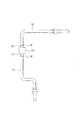
【解決手段】継手本体20の貫通路23に挿通される樹脂製のチューブ部材21の一端部21aの外周に、ユニオンナット22の受口部24の雄ねじ26への締付け作用を受けて入口側シール部25に密着状に当接する膨出部31と、内奥側シール部27に密着状に当接する嵌合凸部32とを有する環状シール部30を一体に樹脂成形する。チューブ部材21の他端部21bは、他の樹脂製チューブ部材38の端部と突き合せ融着する融着部とする。
【選択図】図1
Description
また、前記膨出部の外端面は垂直に形成し、この膨出部の垂直な外端面と、この外端面から軸方向外方へ延びるチューブ部材の他端部の外面とが交わる入り隅部に、チューブ部材の他端部の外径より大きく、前記膨出部の外径より小さい外径の厚肉部を付けて、チューブ部材を前記入り隅部を屈曲点として折れ曲がり難くすることができる。
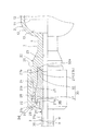
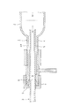
図1は一実施形態を示すもので、この実施形態では、図4に示す従来例のものと同様に半導体製造装置等に使用されるクリーンガスの供給路1における樹脂製管継手構造に適用したものであり、上流側部分を構成するフィルタ2とその下流側部分を構成する二次側配管3とを連結する融着型の樹脂製管継手構造である。フィルタ2それ自体は図3に示すフィルタと同じもので、フィルタハウジング10内を、適宜のフィルタ部材11により、図示しない一次側配管から使用目的に応じた加圧ガス(窒素、空気、不活性ガス等)が流入する一次側空間12と、フィルタ部材11を通過した加圧ガス、つまり清浄化処理されたクリーンガスが流出する二次側空間13とに区画してなるものである。
(チューブ部材の嵌合凸部と継手本体の内奥側シール部の変形例)
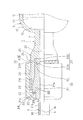
チューブ部材21の嵌合凸部32と継手本体20の内奥側シール部27とは前記実施形態以外に、図2に示すような実施形態を採用することもできる。すなわち、図2に示すように、継手本体20の内奥側シール部27において、継手本体20の受口部24の内奥に受口部方向に向けて漸次拡径したテーパ状に形成された第1の内奥側シール部36Aと、軸線Xと平行な環状溝よりなる第3の内奥側シール部36Cが形成される。
環状シール部を左右対称に持つ1対のチューブ部材を成形し、成形後、そのチューブ部材の中央部を切断することにより2つの所要形状のチューブ部材を得ることができる。
チューブ部材21の一端部21aの外周に環状シール部30を一体加工する手段としては、チューブ部材21と環状シール部30とを一体に樹脂成形するに代えて、切削加工によりチューブ部材21の一端部21aの外周に環状シール部30を一体加工すること、あるいは環状シール部30をチューブ部材21とは別体に成形し、この環状シール部30をチューブ部材21の外周に溶接することは任意である。
本発明の樹脂製管継手構造の継手本体20としては、各図示例のように貫通路23を軸線X方向に形成するソケット形状のものに限られず、そのほかに貫通路を直交状に形成するT形状、エルボ形状、あるいは貫通路を交差状に形成する十字形状のものにも適用でき、またフィルタ2以外の、例えば、流量計、圧力計等の流体制御機器などに一体に突出形成される樹脂製管継手、またはそれら流体制御機器等と別体の樹脂製管継手にも同様に適用できる。
21 チューブ部材
21a チューブ部材の一端部
21b チューブ部材の他端部
22 ユニオンナット
23 貫通路
24 受口部
25 入口側シール部
26 雄ねじ
27 内奥側シール部
28 雌ねじ
29 内向き鍔部
30 環状シール部
31 膨出部
32 嵌合凸部
33 厚肉部
38 他の樹脂製チューブ部材
Claims (5)
- 貫通路を有し、この貫通路の一端に受口部を設けた継手本体と、前記継手本体の貫通路に挿通される樹脂製のチューブ部材と、前記チューブ部材の外周に遊嵌され、前記受口部の外周の雄ねじに螺合される雌ねじを有し、かつ一端部に内向きに張り出した環状の内向き鍔部を有するユニオンナットと、を備えている樹脂製管継手構造において、
前記受口部の開口端内周に、受口部外方に向けて漸次拡径したテーパ状の入口側シール部を、受口部の前記入口側シール部より内奥に少なくとも1つの内奥側シール部をそれぞれ設けており、
前記チューブ部材の一端部の外周に、前記ユニオンナットの前記受口部の雄ねじへの締付けにより前記内向き鍔部による押圧作用を受けて前記入口側シール部に密着状に当接する膨出部と、前記内奥側シール部に密着状に当接する嵌合凸部とを有する環状シール部が一体加工されており、
前記チューブ部材の前記受口部より外方へ突出する他端部は、他の樹脂製チューブ部材の端部と突き合せ融着する融着部としていることを特徴とする、融着型の樹脂製管継手構造。 - 前記環状シール部と前記チューブ部材が一体に樹脂成形されている、請求項1記載の融着型の樹脂製管継手構造。
- 前記環状シール部が切削加工によって前記チューブ部材に一体加工されている、請求項1記載の融着型の樹脂製管継手構造。
- 前記環状シール部が前記チューブ部材に溶接することで一体加工されている、請求項1記載の融着型の樹脂製管継手構造。
- 前記膨出部の外端面は垂直に形成し、この膨出部の垂直な外端面と、この外端面から軸方向外方へ延びるチューブ部材の他端部の外面とが交わる入り隅部に、チューブ部材の他端部の外径より大きく、前記膨出部の外径より小さい外径の厚肉部を付けている、請求項1ないし4のいずれか1項に記載の融着型の樹脂製管継手構造。
Priority Applications (1)
| Application Number | Priority Date | Filing Date | Title |
|---|---|---|---|
| JP2005161282A JP4227975B2 (ja) | 2005-06-01 | 2005-06-01 | 融着型のフッ素樹脂製管継手構造 |
Applications Claiming Priority (1)
| Application Number | Priority Date | Filing Date | Title |
|---|---|---|---|
| JP2005161282A JP4227975B2 (ja) | 2005-06-01 | 2005-06-01 | 融着型のフッ素樹脂製管継手構造 |
Related Parent Applications (1)
| Application Number | Title | Priority Date | Filing Date |
|---|---|---|---|
| JP2003193403A Division JP3865396B2 (ja) | 2003-07-08 | 2003-07-08 | 融着型の樹脂製管継手構造 |
Publications (2)
| Publication Number | Publication Date |
|---|---|
| JP2005291500A true JP2005291500A (ja) | 2005-10-20 |
| JP4227975B2 JP4227975B2 (ja) | 2009-02-18 |
Family
ID=35324633
Family Applications (1)
| Application Number | Title | Priority Date | Filing Date |
|---|---|---|---|
| JP2005161282A Expired - Lifetime JP4227975B2 (ja) | 2005-06-01 | 2005-06-01 | 融着型のフッ素樹脂製管継手構造 |
Country Status (1)
| Country | Link |
|---|---|
| JP (1) | JP4227975B2 (ja) |
Cited By (2)
| Publication number | Priority date | Publication date | Assignee | Title |
|---|---|---|---|---|
| JP2012102871A (ja) * | 2010-10-14 | 2012-05-31 | Takei Jushi Seisakusho:Kk | 管体一体型継手と管体の連結構造 |
| US11518114B2 (en) | 2019-06-07 | 2022-12-06 | Fit-Line, Inc. | Method and apparatus to assemble a high purity liquid distribution system |
-
2005
- 2005-06-01 JP JP2005161282A patent/JP4227975B2/ja not_active Expired - Lifetime
Cited By (4)
| Publication number | Priority date | Publication date | Assignee | Title |
|---|---|---|---|---|
| JP2012102871A (ja) * | 2010-10-14 | 2012-05-31 | Takei Jushi Seisakusho:Kk | 管体一体型継手と管体の連結構造 |
| US11518114B2 (en) | 2019-06-07 | 2022-12-06 | Fit-Line, Inc. | Method and apparatus to assemble a high purity liquid distribution system |
| US12023873B2 (en) | 2019-06-07 | 2024-07-02 | Fit-Line, Inc. | Method and apparatus to assemble a high purity liquid distribution system |
| US12337549B2 (en) | 2019-06-07 | 2025-06-24 | Fit-Line, Inc. | Method and apparatus to assemble a high purity liquid distribution system |
Also Published As
| Publication number | Publication date |
|---|---|
| JP4227975B2 (ja) | 2009-02-18 |
Similar Documents
| Publication | Publication Date | Title |
|---|---|---|
| EP0784770B1 (en) | Dual containment fitting | |
| JP3711365B2 (ja) | コンポーネント対コンポーネントのシール方法 | |
| US6776440B2 (en) | Method and structure for preventing slipping-off of a tube in a pipe joint made of resin | |
| TWI667428B (zh) | 樹脂製管接頭構造 | |
| KR101887260B1 (ko) | 이너 링 | |
| CN115398126B (zh) | 密封部件 | |
| JP2003065479A (ja) | 柔軟性補強パイプの端部に装着される再使用可能カップリング | |
| CN103748397A (zh) | 用于管路或软管管路的、带有锥形螺纹的耐高压的螺旋连接部 | |
| EP4279788B1 (en) | Push-fitting | |
| JP4227975B2 (ja) | 融着型のフッ素樹脂製管継手構造 | |
| JP3865396B2 (ja) | 融着型の樹脂製管継手構造 | |
| JP3865395B2 (ja) | 樹脂製管継手構造 | |
| US7942165B2 (en) | Connection structure between integrated panel and fluid device | |
| KR101842448B1 (ko) | 기밀구조가 강화된 이중관 튜브용 피팅 | |
| US20240044425A1 (en) | Pipe joint | |
| US20100013213A1 (en) | Structure for connection between integrated panel and fluid device | |
| US20090072536A1 (en) | Connection Structure of Stack Panel to Fluid Device | |
| KR101842173B1 (ko) | 기밀구조가 강화된 배관용 피팅 | |
| JP3686846B2 (ja) | 樹脂製管継手構造 | |
| US12025244B2 (en) | Inner ring and pipe joint | |
| JPH0750628Y2 (ja) | 配管用継手 | |
| CN116194701A (zh) | 内环以及管接头 | |
| KR102895943B1 (ko) | 슈페리얼 마스터락 피팅 | |
| JP2005046685A (ja) | 樹脂製ノズル | |
| JP5566668B2 (ja) | 管継手 |
Legal Events
| Date | Code | Title | Description |
|---|---|---|---|
| A977 | Report on retrieval |
Free format text: JAPANESE INTERMEDIATE CODE: A971007 Effective date: 20080229 |
|
| A131 | Notification of reasons for refusal |
Free format text: JAPANESE INTERMEDIATE CODE: A131 Effective date: 20080311 |
|
| A521 | Request for written amendment filed |
Free format text: JAPANESE INTERMEDIATE CODE: A523 Effective date: 20080509 |
|
| TRDD | Decision of grant or rejection written | ||
| A01 | Written decision to grant a patent or to grant a registration (utility model) |
Free format text: JAPANESE INTERMEDIATE CODE: A01 Effective date: 20081104 |
|
| A01 | Written decision to grant a patent or to grant a registration (utility model) |
Free format text: JAPANESE INTERMEDIATE CODE: A01 |
|
| A61 | First payment of annual fees (during grant procedure) |
Free format text: JAPANESE INTERMEDIATE CODE: A61 Effective date: 20081201 |
|
| FPAY | Renewal fee payment (event date is renewal date of database) |
Free format text: PAYMENT UNTIL: 20111205 Year of fee payment: 3 |
|
| R150 | Certificate of patent or registration of utility model |
Ref document number: 4227975 Country of ref document: JP Free format text: JAPANESE INTERMEDIATE CODE: R150 Free format text: JAPANESE INTERMEDIATE CODE: R150 |
|
| FPAY | Renewal fee payment (event date is renewal date of database) |
Free format text: PAYMENT UNTIL: 20111205 Year of fee payment: 3 |
|
| FPAY | Renewal fee payment (event date is renewal date of database) |
Free format text: PAYMENT UNTIL: 20121205 Year of fee payment: 4 |
|
| FPAY | Renewal fee payment (event date is renewal date of database) |
Free format text: PAYMENT UNTIL: 20121205 Year of fee payment: 4 |
|
| FPAY | Renewal fee payment (event date is renewal date of database) |
Free format text: PAYMENT UNTIL: 20131205 Year of fee payment: 5 |
|
| FPAY | Renewal fee payment (event date is renewal date of database) |
Free format text: PAYMENT UNTIL: 20141205 Year of fee payment: 6 |
|
| EXPY | Cancellation because of completion of term |