JP2005291500A - Fusion type resin pipe coupling structure - Google Patents
Fusion type resin pipe coupling structure Download PDFInfo
- Publication number
- JP2005291500A JP2005291500A JP2005161282A JP2005161282A JP2005291500A JP 2005291500 A JP2005291500 A JP 2005291500A JP 2005161282 A JP2005161282 A JP 2005161282A JP 2005161282 A JP2005161282 A JP 2005161282A JP 2005291500 A JP2005291500 A JP 2005291500A
- Authority
- JP
- Japan
- Prior art keywords
- tube member
- fusion
- resin
- joint structure
- pipe joint
- Prior art date
- Legal status (The legal status is an assumption and is not a legal conclusion. Google has not performed a legal analysis and makes no representation as to the accuracy of the status listed.)
- Granted
Links
- 239000011347 resin Substances 0.000 title claims abstract description 58
- 229920005989 resin Polymers 0.000 title claims abstract description 58
- 230000004927 fusion Effects 0.000 title claims abstract description 15
- 230000008878 coupling Effects 0.000 title abstract 3
- 238000010168 coupling process Methods 0.000 title abstract 3
- 238000005859 coupling reaction Methods 0.000 title abstract 3
- 238000003825 pressing Methods 0.000 claims description 6
- 238000005520 cutting process Methods 0.000 claims description 4
- 238000003466 welding Methods 0.000 claims description 2
- 239000012530 fluid Substances 0.000 abstract description 23
- 230000002159 abnormal effect Effects 0.000 abstract description 9
- 230000001747 exhibiting effect Effects 0.000 abstract 1
- 238000000605 extraction Methods 0.000 abstract 1
- 230000003449 preventive effect Effects 0.000 abstract 1
- 230000008961 swelling Effects 0.000 abstract 1
- 230000002093 peripheral effect Effects 0.000 description 11
- 239000007788 liquid Substances 0.000 description 10
- 239000007789 gas Substances 0.000 description 9
- 238000004519 manufacturing process Methods 0.000 description 5
- 238000005452 bending Methods 0.000 description 4
- 239000000126 substance Substances 0.000 description 4
- 239000004065 semiconductor Substances 0.000 description 3
- IJGRMHOSHXDMSA-UHFFFAOYSA-N Atomic nitrogen Chemical compound N#N IJGRMHOSHXDMSA-UHFFFAOYSA-N 0.000 description 2
- 238000010276 construction Methods 0.000 description 2
- 230000004048 modification Effects 0.000 description 2
- 238000012986 modification Methods 0.000 description 2
- 238000000465 moulding Methods 0.000 description 2
- 238000000746 purification Methods 0.000 description 2
- 239000002033 PVDF binder Substances 0.000 description 1
- 239000004813 Perfluoroalkoxy alkane Substances 0.000 description 1
- 238000009825 accumulation Methods 0.000 description 1
- 239000003570 air Substances 0.000 description 1
- 230000003247 decreasing effect Effects 0.000 description 1
- 235000013305 food Nutrition 0.000 description 1
- 238000010438 heat treatment Methods 0.000 description 1
- 239000011261 inert gas Substances 0.000 description 1
- 230000014759 maintenance of location Effects 0.000 description 1
- 239000000463 material Substances 0.000 description 1
- 235000013372 meat Nutrition 0.000 description 1
- 238000000034 method Methods 0.000 description 1
- 229910052757 nitrogen Inorganic materials 0.000 description 1
- 229920011301 perfluoro alkoxyl alkane Polymers 0.000 description 1
- 239000004810 polytetrafluoroethylene Substances 0.000 description 1
- 229920001343 polytetrafluoroethylene Polymers 0.000 description 1
- 229920002981 polyvinylidene fluoride Polymers 0.000 description 1
- 238000011176 pooling Methods 0.000 description 1
- 230000002265 prevention Effects 0.000 description 1
- 238000007789 sealing Methods 0.000 description 1
- 229910021642 ultra pure water Inorganic materials 0.000 description 1
- 239000012498 ultrapure water Substances 0.000 description 1
- 238000011144 upstream manufacturing Methods 0.000 description 1
Images
Landscapes
- Branch Pipes, Bends, And The Like (AREA)
Abstract
Description
本発明は、融着型の樹脂製管継手構造に係り、より詳しくは半導体製造や医療・医薬品製造、食品加工、化学工業等の製造工程で取り扱われる高純度液や超純水の配管や流体制御機器等に好適に使用される樹脂製管継手構造に関するものである。 The present invention relates to a fusion-type resin pipe joint structure, and more specifically, a pipe or fluid of high-purity liquid or ultrapure water handled in manufacturing processes such as semiconductor manufacturing, medical / pharmaceutical manufacturing, food processing, chemical industry, etc. The present invention relates to a resin pipe joint structure that is suitably used for control devices and the like.
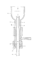
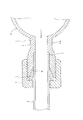
この種の樹脂製管継手構造として、たとえば、図3や図4に示すような形態のもの(以下、「第1従来例」という。)が知られている(例えば、特許文献1参照)。その樹脂製管継手構造は、半導体の製造装置等に使用されるクリーンガスの供給路1においてフィルタ2とその二次側配管3とを連結するものである。すなわち、フィルタ2の二次側出口部4に二次側配管3の管端部5を差し込んだうえ、二次側出口部4の口部4aの先端側に固着された継手リング6に螺合させたユニオンナット7を締め付けて、継手リング6の先端テーパ面8に衝合させた食込みリング9を二次側配管3の外周面に圧接又は食い込ませることにより、二次側出口部4と二次側配管3とを食込みリング9によるシール状態で連結している。
As this type of resin pipe joint structure, for example, a structure as shown in FIGS. 3 and 4 (hereinafter referred to as “first conventional example”) is known (for example, see Patent Document 1). The resin pipe joint structure connects the
また、図5に示すような流体制御機器(以下、「第2従来例」という。)も知られている(例えば、特許文献2参照。)その流体制御機器は、制御機器本体15の入液側と出液側に樹脂製接続口16、17を突設し、各接続口16、17にそれぞれ流路構成用の樹脂製チューブ18、19を突き合せ状態に融着(溶着)Wしたものである。
In addition, a fluid control device as shown in FIG. 5 (hereinafter referred to as “second conventional example”) is also known (see, for example, Patent Document 2).
しかるに、二次側配管3とは別体に形成される食込みリング9により二次側出口部4と二次側配管3とをシール状態に連結する第1従来例の樹脂製管継手構造では、ユニオンナット7を締め付けることにより食込みリング9を二次側配管3の外周面に圧接又は食い込ませるとはいうものの、そのユニオンナット7の締め付けによる食込みリング9の圧接又は食い込み度合いには限界があって、食込みリング9の内周面と二次側配管3の外周面との間に僅かな隙間が生じやすい。このため、フィルタ2から送られてくる加圧ガスが前記隙間に侵入して抜けにくくガス溜まりとなり、ガスの高純度化を阻害する。また、この樹脂製管継手構造が液体供給配管等に使用される場合は、前記隙間に侵入した液体は抜けにくく液溜まりとなり、液の高純度化を阻害する。
However, in the resin pipe joint structure of the first conventional example in which the secondary
また、二次側配管3はフィルタ2の二次側出口部4から抜け出ないようにする必要があり、この抜け止めは食込みリング9の二次側配管3の外周面への圧接又は食い込みでもって行われるが、かかる二次配管3の抜け止め手段では使用条件によっては充分ではない場合がある。すなわち、二次側配管3に加わる通常使用の流体圧力に対する引抜き抵抗は、前記の抜け止め手段でも問題ないが、輸送される流体の温度が通常の使用温度を越えたり、流体の圧力が通常使用の圧力をはるかに越えたりする厳しい使用条件下で異常な流体の圧力が加わった場合や、内圧以外の機械的な引抜き力が異常に加わった場合において、とくに危険な薬品を輸送するときに安全性を確保することが非常に重要な課題である。このため、この樹脂製管継手の使用条件(温度や圧力)を制限する必要があった。
Further, it is necessary to prevent the
また、第1従来例の樹脂製管継手構造においては二次側配管3の引抜き抵抗はユニオンナット7の締め付けによる食込みリング9の二次側配管3の外周面への圧接又は食い込みのみでもってなされているが、これでは初期の施工ミスや経時変化によってユニオンナット7の締付力が弱くなった場合に安全性の問題が生じる。とくに二次側配管3が耐熱、耐薬品性に優れるフッ素樹脂(PFA等)からなる場合摩擦係数が小さく滑り易いため、二次側配管3の強い引抜きに対する抵抗が少なくて抜け出す恐れがある。
Further, in the resin pipe joint structure of the first conventional example, the pull-out resistance of the
図5に示す第2従来例の流体制御機器では、制御機器本体15の入液側及び出液側から樹脂製接続口16、17が一体に突設しているので、その接続口16、17に樹脂製チューブ18、19を融着するに際し融着機を用いるにしても制御機本体15が嵩張って融着作業の邪魔になるため融着作業が行い難い。また、樹脂製接続口16、17には、それと同一径の樹脂製チューブ18、19の融着しかできず、異径の樹脂製チューブの融着は不可能であるという不利不便があった。
本発明は、このような問題を解決するためになされたもので、その目的とするところは、第1従来例のような二次側配管等を構成するチューブ部材と継手本体との間のシール構造及びチューブ部材の抜止め手段に工夫を凝らすことにより、前記ガスや液の流体溜まり問題を解消することができて流体の高純度化の障害を取り除くことができ、また異常な流体圧力や内圧以外の機械的な異常な引抜き力が加わった場合においてもチューブ部材の抜止め機能を十分に発揮できて安全性を確保でき、使用条件に制約がなくなり、あらゆる条件で使用できるとともに設計の自由度が増す融着型の樹脂製管継手構造を提供することにある。また、本発明の目的は、チューブ部材の融着作業の簡易化を図れ、また異径チューブ部材の融着を可能にする融着型の樹脂製管継手構造を提供することにある。 The present invention has been made in order to solve such a problem, and its object is to provide a seal between a tube member and a joint body constituting a secondary side pipe or the like as in the first conventional example. By devising the structure and the tube member retention means, it is possible to eliminate the problem of gas and liquid pooling and eliminate the obstacles to high purity of the fluid, as well as abnormal fluid pressure and internal pressure. Even when a mechanical abnormal pulling force other than the above is applied, the tube member's retaining function can be fully exerted to ensure safety, there are no restrictions on the use conditions, and it can be used in all conditions and the design freedom An object of the present invention is to provide a fusion-type resin pipe joint structure in which the number of welds increases. Another object of the present invention is to provide a fusion-type resin pipe joint structure that can simplify the fusion work of tube members and enables fusion of different-diameter tube members.
本発明の融着型の樹脂製管継手構造は、貫通路を有し、この貫通路の一端に受口部を設けた継手本体と、この継手本体の貫通路に挿通される樹脂製のチューブ部材と、このチューブ部材の外周に遊嵌され、前記受口部の外周の雄ねじに螺合される雌ねじを有し、かつ一端部に内向きに張り出した環状の内向き鍔部を有するユニオンナットと、を備えている樹脂製管継手構造において、前記受口部の開口端内周に、受口部外方に向けて漸次拡径したテーパ状の入口側シール部を、受口部の前記入口側シール部より内奥に少なくとも1つの内奥側シール部をそれぞれ設けており、前記チューブ部材の一端部の外周に、前記ユニオンナットの前記受口部の雄ねじへの締付けにより前記内向き鍔部による押圧作用を受けて前記入口側シール部に密着状に当接する膨出部と、前記内奥側シール部に密着状に当接する嵌合凸部とを有する環状シール部が一体加工されており、前記チューブ部材の前記受口部より外方へ突出する他端部は、他の樹脂製チューブ部材の端部と突き合せ融着する融着部としていることに特徴を有するものである。 The fusion-type resin pipe joint structure of the present invention has a through-passage, a joint main body provided with a receiving portion at one end of the through-passage, and a resin tube inserted into the through-passage of the joint main body A union nut having a member, a female screw that is loosely fitted to the outer periphery of the tube member, and is screwed to a male screw on the outer periphery of the receiving portion, and an annular inward flange portion projecting inwardly at one end portion In the resin pipe joint structure comprising: a tapered inlet-side seal portion that gradually increases in diameter toward the outside of the receiving portion on the inner periphery of the opening end of the receiving portion; At least one inner back side seal portion is provided inward from the inlet side seal portion, and the inward flange is fastened to the outer periphery of one end portion of the tube member by tightening the male nut of the receiving portion of the union nut. In close contact with the inlet-side seal part under the pressing action of the part An annular seal portion having a bulging portion that comes into contact and a fitting convex portion that comes into close contact with the inner back side seal portion is integrally processed, and protrudes outward from the receiving portion of the tube member. The other end portion is characterized in that it is a fusion portion that is abutted and fused with an end portion of another resin tube member.
この場合において、前記環状シール部と前記チューブ部材は一体に樹脂成形することができる。また、前記環状シール部は切削加工によって前記チューブ部材に一体加工することもできる。また前記環状シール部は前記チューブ部材に溶接することで一体加工することもできる。
また、前記膨出部の外端面は垂直に形成し、この膨出部の垂直な外端面と、この外端面から軸方向外方へ延びるチューブ部材の他端部の外面とが交わる入り隅部に、チューブ部材の他端部の外径より大きく、前記膨出部の外径より小さい外径の厚肉部を付けて、チューブ部材を前記入り隅部を屈曲点として折れ曲がり難くすることができる。
In this case, the annular seal portion and the tube member can be integrally molded with resin. Moreover, the said annular seal part can also be integrally processed by the said tube member by cutting. Moreover, the said annular seal part can also be integrally processed by welding to the said tube member.
In addition, the outer end surface of the bulging portion is formed vertically, and the corner portion where the vertical outer end surface of the bulging portion intersects the outer surface of the other end portion of the tube member extending axially outward from the outer end surface. A thick wall portion having an outer diameter larger than the outer diameter of the other end portion of the tube member and smaller than the outer diameter of the bulging portion can be attached to the tube member so that the tube member is not easily bent at the corner portion as a bending point. .
前記構成の融着型の樹脂製管継手構造によれば、ユニオンナットを締め付けることで継手本体の入口側シール部に密着状に当接する膨出部と、内奥側シール部に密着状に当接する嵌合凸部とを有する環状シール部がチューブ部材の外周一部に一体加工されて、チューブ部材の外周と環状シール部との間に隙間が生じないものとしている。したがって、前述した従来の樹脂製管継手構造のごとき流体溜まり問題は無くなり流体の高純度化の障害を取り除くことができる。 According to the fusion-type resin pipe joint structure having the above-described structure, the union nut is tightened to tightly contact the bulging portion that is in close contact with the inlet-side seal portion of the joint body and the inner back-side seal portion. An annular seal portion having a fitting convex portion that comes into contact is integrally processed on a part of the outer periphery of the tube member so that no gap is generated between the outer periphery of the tube member and the annular seal portion. Therefore, there is no fluid pool problem as in the conventional resin pipe joint structure described above, and the obstacle to high purity of the fluid can be removed.
また、異常な流体の圧力や内圧以外の機械的な異常な引抜き力がチューブ部材に加わった場合においても、ユニオンナットの内向き鍔部により押圧されている環状シール部はチューブ部材に一体加工されているので引抜き力に十分に対抗することができ、チューブ部材の引抜き阻止力が高められて安全性を確保でき、使用条件(温度、圧力)に制約がなくなり、あらゆる条件で使用できるとともに設計の自由度を増すことができる。 In addition, even when an abnormal mechanical pressure other than abnormal fluid pressure or internal pressure is applied to the tube member, the annular seal portion pressed by the inward flange of the union nut is integrally processed on the tube member. Therefore, it can sufficiently counter the pulling force, and the tube member's pulling-out prevention force is enhanced to ensure safety, and there are no restrictions on the use conditions (temperature, pressure), and it can be used in all conditions and is designed. The degree of freedom can be increased.
チューブ部材と継手本体とは分離可能であり、この分離状態下でチューブ部材の他端部の融着部に他の樹脂製チューブ部材の端部を突き合せ融着することができるので、その融着に際し融着機を使用する場合も容易に融着作業を行うことができる。また、チューブ部材とは異径の他の樹脂製チューブ部材を融着する場合は、チューブ部材の他端部の径を他の異径の樹脂製チューブ部材の径と同径に形成しておくことにより可能である。 The tube member and the joint body can be separated, and the end of another resin tube member can be abutted and fused to the fused part of the other end of the tube member in this separated state. Even when a fusing machine is used for wearing, the fusing operation can be easily performed. In addition, when fusing another resin tube member having a different diameter from the tube member, the diameter of the other end of the tube member is formed to be the same as the diameter of the other resin tube member having a different diameter. Is possible.
以下、本発明の好適な実施形態を図面に基づき説明する。 Preferred embodiments of the present invention will be described below with reference to the drawings.
〔実施例1〕
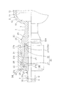
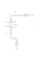
図1は一実施形態を示すもので、この実施形態では、図4に示す従来例のものと同様に半導体製造装置等に使用されるクリーンガスの供給路1における樹脂製管継手構造に適用したものであり、上流側部分を構成するフィルタ2とその下流側部分を構成する二次側配管3とを連結する融着型の樹脂製管継手構造である。フィルタ2それ自体は図3に示すフィルタと同じもので、フィルタハウジング10内を、適宜のフィルタ部材11により、図示しない一次側配管から使用目的に応じた加圧ガス(窒素、空気、不活性ガス等)が流入する一次側空間12と、フィルタ部材11を通過した加圧ガス、つまり清浄化処理されたクリーンガスが流出する二次側空間13とに区画してなるものである。
[Example 1]
FIG. 1 shows one embodiment. In this embodiment, the present invention is applied to a resin pipe joint structure in a
すなわち、この実施形態における本発明に係る融着型の樹脂製管継手構造は、フィルタ2の二次側空間13に連通する二次側出口部4の先端側に一体に形成される継手本体20と、二次側配管3を構成するチューブ部材21、及びユニオンナット22とを備えてなる。これら継手本体20、チューブ部材21及びユニオンナット22は耐熱、耐薬品性に優れるフッ素樹脂(例えば、PFA、PTFE、PVDF等)、又はその他の樹脂によって成形される。
That is, the fusion-type resin pipe joint structure according to the present invention in this embodiment is a
継手本体20は貫通路23を有し、この貫通路23の一端に受口部24を設け、この受口部24の開口端内周に、受口部外方に向けて漸次拡径したテーパ状の入口側シール部25を設ける。受口部24の外周には雄ねじ26が形成される。受口部24の入口側シール部25より内奥には少なくとも1つの内奥側シール部27を設ける。図示例では、内奥側シール部27が、受口部24の内奥部に受口部方向に向けて漸次縮径したテーパ面27aを外周側に有する断面V形状に形成された環状の第1の内奥側シール部27Aが設けられている。
The
ユニオンナット22はこれの内周に継手本体20の雄ねじ26に螺合される雌ねじ28を形成し、かつ一端部に環状の内向き鍔部29を内向きに張り出し形成している。また、チューブ部材21の一端部21aの内周面と継手本体20の管通路23の内周面とが面一となるように設定される。
The
チューブ部材21はこれの一端部21aの外周に環状シール部30を一体に樹脂成形している。環状シール部30は継手本体20の入口側シール部25に当接するテーパ面31aを内端側に形成した膨出部31と、この膨出部31のテーパ面31a側に連続して形成され、継手本体20の内奥側シール部27Aのテーパ面27aに当接するテーパ面32aを内端側に形成した嵌合凸部32とを有する形に形成している。チューブ部材21の他端部21bは、他の樹脂製チューブ部材38の端部と突き合せ融着する融着部とする。
The
前記構成の融着型の樹脂製管継手構造において、チューブ部材21の他端部21bの融着部には他の樹脂製チューブ部材38の一端部を突き合せ状に融着Wするが、このときは、チューブ部材21を継手本体20の受口部24に挿通する前に、または既にチューブ部材21が継手本体20に仮挿通されている場合はユニオンナット22を緩めて一旦チューブ部材21を継手本体20から抜き出してから融着Wする。その融着には、例えば、赤外線加熱による融着機を用いる。この場合、チューブ部材21は継手本体20とは分離されているので、融着時に継手本体20が邪魔になることはなく、容易に融着作業することができる。
In the fusion-type resin pipe joint structure having the above-described configuration, one end part of another resin-made
かかる融着接合は、チューブ部材21の一端部21aの内径と他の樹脂製チューブ材38の内径とが同一のものに限られず、チューブ部材21の一端部21aの内径とは異径の他の樹脂製チューブ部材38を融着することもできる。
The fusion bonding is not limited to the inner diameter of the one
かくして、チューブ部材21の一端部21aを継手本体20の受口部24に挿通したうえ、予めチューブ部材21の外周に遊嵌させてあるユニオンナット22の雌ねじ28を継手本体20の雄ねじ26に螺合させて締め付ける。すると、ユニオンナット22の内向き鍔部29がチューブ部材21の膨出部31の軸線Xに対し垂直な外端面31bに当接して環状シール部30ごとチューブ部材21全体を継手本体20側に強く押圧する。
Thus, the one
かかるユニオンナット22の締め付けによる強い押圧作用により嵌合凸部32のテーパ面32aが継手本体20の第1の内奥側シール部27Aのテーパ面27aに、また膨出部31のテーパ面31aが継手本体20の入口側シール部25にそれぞれ強い面圧で密着して気密状にシールされ、さらに嵌合凸部32のテーパ面32aが第1の内奥側シール部27Aのテーパ面27aに押し付けられることにより該内奥側シール部27Aが縮径変形を加えられる。したがって、フィルタ2の二次側出口部4からチューブ部材21へ流出する流体が継手本体20の貫通路23とチューブ部材21の外周との間から外部へ漏れるのを確実に防止できる。
Due to the strong pressing action by tightening the
このようにフィルタ2の二次側出口部4とチューブ部材21とをシール状態に連結する融着型の樹脂製管継手構造によれば、ユニオンナット22の締め付けにより継手本体20の入口側シール部25及び内奥側シール部27に密着状に当接する環状シール部30はチューブ部材21の外周に一体成形されていて該チューブ部材21との間に隙間を形成するようなことがないので、前述した従来の樹脂製管継手構造のごとき流体溜まり問題を解消することができて流体の高純度化に寄与することができる。
Thus, according to the fusion-type resin pipe joint structure that connects the
また、そのようにチューブ部材21に一体成形されユニオンナット22の内向き鍔部29により押圧されている環状シール部30は、異常な流体の圧力や内圧以外の機械的な異常な引抜き力がチューブ部材21に加わった場合においてもその引抜き力に十分に対抗することができ、チューブ部材21の引抜き抵抗を上げることができ、常温流体の時は勿論のこと、高温、高圧流体の使用条件でも使用できる。
Further, the
前記チューブ部材21の環状シール部30において、図1に示すように、膨出部31の外端面31bは軸線Xに対し垂直に形成してあると、ユニオンナット22の内向き鍔部29の内面と面接触させることができるため、ユニオンナット22の締め付けに伴い内向き鍔部29により膨出部31を安定確実に押圧させることができるとともに、その押圧状態を堅持できて有利である。しかし、チューブ部材21が膨出部31の垂直な外端面31bと、この外端面31bから軸方向外方へ延びる他端部21bの外面とが交わる入り隅部を屈曲点として折れ曲がりやすくなり、この折れ曲がりにより膨出部31の外端面31bがユニオンナット22の内向き鍔部29の内面から離れやすくなるというデメリットがある。
In the
そこで、膨出部31の垂直な外端面31bと他端部21bの外面とが交わる入り隅部には他端部21bの外径より大きく、膨出部31の外径より小さい外径の厚肉部33を付けておくことが好ましい。このように厚肉部33を付けておくと、チューブ部材21が前記入り隅部を屈曲点として折れ曲がるのをできる限り抑えることができる。したがって、チューブ部材21の折れ曲がりにより膨出部31の外端面31bがユニオンナット22の内向き鍔部29の内面から離れるような不具合がなくなり、常時ユニオンナット22の内向き鍔部29を膨出部31の外端面31bに対し押圧接当させた状態を確実に維持できることになる。
Therefore, at the corner where the perpendicular
また、ユニオンナット22の内向き鍔部29と膨出部31の垂直な外端面31bとの当接係合状態をより確実に保持するためには、ユニオンナット22の内向き鍔部29の内面と膨出部31の外端面31bの間において、膨出部31の外端面31bに凸部34を設ける一方、内向き鍔部29の内面に該凸部34が係合する凹部35を設けておくことが好ましい。
Moreover, in order to hold | maintain the contact | abutting engagement state of the
〔実施例2〕
(チューブ部材の嵌合凸部と継手本体の内奥側シール部の変形例)
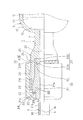
チューブ部材21の嵌合凸部32と継手本体20の内奥側シール部27とは前記実施形態以外に、図2に示すような実施形態を採用することもできる。すなわち、図2に示すように、継手本体20の内奥側シール部27において、継手本体20の受口部24の内奥に受口部方向に向けて漸次拡径したテーパ状に形成された第1の内奥側シール部36Aと、軸線Xと平行な環状溝よりなる第3の内奥側シール部36Cが形成される。
[Example 2]
(Modification example of fitting convex part of tube member and inner back side seal part of joint body)
In addition to the above-described embodiment, the
一方、チューブ部材21の嵌合凸部32において、チューブ部材21の膨出部31のテーパ面31a側に、第1の内奥側シール部36Aに当接するテーパ面をもつ第1の嵌合凸部32Aと、この嵌合凸部32Aより径方向外方で且つ軸線方向内方へ向かって平行に突出され、第3の内奥側シール部36Cに圧入することで径方向の面圧を発生させる円筒形状の第2の嵌合凸部32Bとが形成される。また、チューブ部材21の一端部21aの内周面と継手本体20の管通路23の内周面とが面一となるように設定される。
On the other hand, in the fitting
そのほかに、第3の内奥側シール部36Cに対し第2の嵌合凸部32Bの外周面のみを密着させてシール部を構成するものであってもよい。
In addition, only the outer peripheral surface of the second fitting
(チューブ部材の成形加工例)
環状シール部を左右対称に持つ1対のチューブ部材を成形し、成形後、そのチューブ部材の中央部を切断することにより2つの所要形状のチューブ部材を得ることができる。
(Example of tube member forming)
By forming a pair of tube members having an annular seal portion symmetrically, and cutting the center portion of the tube members after forming, two tube members having required shapes can be obtained.
(チューブ部材と環状シール部の一体加工手段の変形例)
チューブ部材21の一端部21aの外周に環状シール部30を一体加工する手段としては、チューブ部材21と環状シール部30とを一体に樹脂成形するに代えて、切削加工によりチューブ部材21の一端部21aの外周に環状シール部30を一体加工すること、あるいは環状シール部30をチューブ部材21とは別体に成形し、この環状シール部30をチューブ部材21の外周に溶接することは任意である。
(Variation of integrated processing means for tube member and annular seal part)
As means for integrally processing the
(継手本体の変形例)
本発明の樹脂製管継手構造の継手本体20としては、各図示例のように貫通路23を軸線X方向に形成するソケット形状のものに限られず、そのほかに貫通路を直交状に形成するT形状、エルボ形状、あるいは貫通路を交差状に形成する十字形状のものにも適用でき、またフィルタ2以外の、例えば、流量計、圧力計等の流体制御機器などに一体に突出形成される樹脂製管継手、またはそれら流体制御機器等と別体の樹脂製管継手にも同様に適用できる。
(Modification of joint body)
The
20 継手本体
21 チューブ部材
21a チューブ部材の一端部
21b チューブ部材の他端部
22 ユニオンナット
23 貫通路
24 受口部
25 入口側シール部
26 雄ねじ
27 内奥側シール部
28 雌ねじ
29 内向き鍔部
30 環状シール部
31 膨出部
32 嵌合凸部
33 厚肉部
38 他の樹脂製チューブ部材
DESCRIPTION OF
Claims (5)
前記受口部の開口端内周に、受口部外方に向けて漸次拡径したテーパ状の入口側シール部を、受口部の前記入口側シール部より内奥に少なくとも1つの内奥側シール部をそれぞれ設けており、
前記チューブ部材の一端部の外周に、前記ユニオンナットの前記受口部の雄ねじへの締付けにより前記内向き鍔部による押圧作用を受けて前記入口側シール部に密着状に当接する膨出部と、前記内奥側シール部に密着状に当接する嵌合凸部とを有する環状シール部が一体加工されており、
前記チューブ部材の前記受口部より外方へ突出する他端部は、他の樹脂製チューブ部材の端部と突き合せ融着する融着部としていることを特徴とする、融着型の樹脂製管継手構造。 A joint body having a through-passage and having a receiving portion at one end of the through-passage, a resin tube member inserted through the through-passage of the joint body, and loosely fitted on the outer periphery of the tube member, In a resin pipe joint structure having a female screw that is screwed to a male screw on the outer periphery of the receiving part, and a union nut having an annular inward flange projecting inwardly at one end part,
A tapered inlet-side seal portion that gradually increases in diameter toward the outside of the receiving portion is provided on the inner periphery of the opening end of the receiving portion. Each side seal part is provided,
A bulging portion that is pressed against the inlet side seal portion in close contact with the outer periphery of one end portion of the tube member by receiving a pressing action by the inward flange portion by tightening the receiving portion of the union nut to the male screw; The annular seal portion having a fitting convex portion that comes into close contact with the inner back side seal portion is integrally processed,
The other end portion of the tube member that protrudes outward from the receiving portion is a fusion portion that is abutted and fused with an end portion of another resin tube member. Pipe joint structure.
The outer end surface of the bulging portion is formed vertically, and a corner portion where the vertical outer end surface of the bulging portion intersects with the outer surface of the other end portion of the tube member extending axially outward from the outer end surface, The fusion-type resin according to any one of claims 1 to 4, wherein a thick-walled portion having an outer diameter larger than the outer diameter of the other end portion of the tube member and smaller than the outer diameter of the bulging portion is attached. Pipe joint structure.
Priority Applications (1)
| Application Number | Priority Date | Filing Date | Title |
|---|---|---|---|
| JP2005161282A JP4227975B2 (en) | 2005-06-01 | 2005-06-01 | Fused fluororesin pipe joint structure |
Applications Claiming Priority (1)
| Application Number | Priority Date | Filing Date | Title |
|---|---|---|---|
| JP2005161282A JP4227975B2 (en) | 2005-06-01 | 2005-06-01 | Fused fluororesin pipe joint structure |
Related Parent Applications (1)
| Application Number | Title | Priority Date | Filing Date |
|---|---|---|---|
| JP2003193403A Division JP3865396B2 (en) | 2003-07-08 | 2003-07-08 | Fusion type resin pipe joint structure |
Publications (2)
| Publication Number | Publication Date |
|---|---|
| JP2005291500A true JP2005291500A (en) | 2005-10-20 |
| JP4227975B2 JP4227975B2 (en) | 2009-02-18 |
Family
ID=35324633
Family Applications (1)
| Application Number | Title | Priority Date | Filing Date |
|---|---|---|---|
| JP2005161282A Expired - Lifetime JP4227975B2 (en) | 2005-06-01 | 2005-06-01 | Fused fluororesin pipe joint structure |
Country Status (1)
| Country | Link |
|---|---|
| JP (1) | JP4227975B2 (en) |
Cited By (2)
| Publication number | Priority date | Publication date | Assignee | Title |
|---|---|---|---|---|
| JP2012102871A (en) * | 2010-10-14 | 2012-05-31 | Takei Jushi Seisakusho:Kk | Pipe body integrated type joint, and connection structure of pipe body |
| US11518114B2 (en) | 2019-06-07 | 2022-12-06 | Fit-Line, Inc. | Method and apparatus to assemble a high purity liquid distribution system |
-
2005
- 2005-06-01 JP JP2005161282A patent/JP4227975B2/en not_active Expired - Lifetime
Cited By (4)
| Publication number | Priority date | Publication date | Assignee | Title |
|---|---|---|---|---|
| JP2012102871A (en) * | 2010-10-14 | 2012-05-31 | Takei Jushi Seisakusho:Kk | Pipe body integrated type joint, and connection structure of pipe body |
| US11518114B2 (en) | 2019-06-07 | 2022-12-06 | Fit-Line, Inc. | Method and apparatus to assemble a high purity liquid distribution system |
| US12023873B2 (en) | 2019-06-07 | 2024-07-02 | Fit-Line, Inc. | Method and apparatus to assemble a high purity liquid distribution system |
| US12337549B2 (en) | 2019-06-07 | 2025-06-24 | Fit-Line, Inc. | Method and apparatus to assemble a high purity liquid distribution system |
Also Published As
| Publication number | Publication date |
|---|---|
| JP4227975B2 (en) | 2009-02-18 |
Similar Documents
| Publication | Publication Date | Title |
|---|---|---|
| EP0784770B1 (en) | Dual containment fitting | |
| JP3711365B2 (en) | Component-to-component sealing method | |
| US6776440B2 (en) | Method and structure for preventing slipping-off of a tube in a pipe joint made of resin | |
| TWI667428B (en) | Resin pipe joint structure | |
| KR101887260B1 (en) | Inner ring | |
| CN115398126B (en) | Sealing member | |
| JP2003065479A (en) | Reusable coupling attached to the end of flexible reinforcement pipe | |
| CN103748397A (en) | High pressure-resistant screw connection for pipelines or hose lines having a tapered thread | |
| EP4279788B1 (en) | Push-fitting | |
| JP4227975B2 (en) | Fused fluororesin pipe joint structure | |
| JP3865396B2 (en) | Fusion type resin pipe joint structure | |
| JP3865395B2 (en) | Resin pipe joint structure | |
| US7942165B2 (en) | Connection structure between integrated panel and fluid device | |
| KR101842448B1 (en) | Fitting for Dual-layer Tube with Enhanced Seal Structure | |
| US20240044425A1 (en) | Pipe joint | |
| US20100013213A1 (en) | Structure for connection between integrated panel and fluid device | |
| US20090072536A1 (en) | Connection Structure of Stack Panel to Fluid Device | |
| KR101842173B1 (en) | Fitting for Tube with Enhanced Seal Structure | |
| JP3686846B2 (en) | Resin pipe joint structure | |
| US12025244B2 (en) | Inner ring and pipe joint | |
| JPH0750628Y2 (en) | Pipe fitting | |
| CN116194701A (en) | Inner ring and pipe joint | |
| KR102895943B1 (en) | Superior Master Lock Union Fitting | |
| JP2005046685A (en) | Resin nozzle | |
| JP5566668B2 (en) | Pipe fitting |
Legal Events
| Date | Code | Title | Description |
|---|---|---|---|
| A977 | Report on retrieval |
Free format text: JAPANESE INTERMEDIATE CODE: A971007 Effective date: 20080229 |
|
| A131 | Notification of reasons for refusal |
Free format text: JAPANESE INTERMEDIATE CODE: A131 Effective date: 20080311 |
|
| A521 | Request for written amendment filed |
Free format text: JAPANESE INTERMEDIATE CODE: A523 Effective date: 20080509 |
|
| TRDD | Decision of grant or rejection written | ||
| A01 | Written decision to grant a patent or to grant a registration (utility model) |
Free format text: JAPANESE INTERMEDIATE CODE: A01 Effective date: 20081104 |
|
| A01 | Written decision to grant a patent or to grant a registration (utility model) |
Free format text: JAPANESE INTERMEDIATE CODE: A01 |
|
| A61 | First payment of annual fees (during grant procedure) |
Free format text: JAPANESE INTERMEDIATE CODE: A61 Effective date: 20081201 |
|
| FPAY | Renewal fee payment (event date is renewal date of database) |
Free format text: PAYMENT UNTIL: 20111205 Year of fee payment: 3 |
|
| R150 | Certificate of patent or registration of utility model |
Ref document number: 4227975 Country of ref document: JP Free format text: JAPANESE INTERMEDIATE CODE: R150 Free format text: JAPANESE INTERMEDIATE CODE: R150 |
|
| FPAY | Renewal fee payment (event date is renewal date of database) |
Free format text: PAYMENT UNTIL: 20111205 Year of fee payment: 3 |
|
| FPAY | Renewal fee payment (event date is renewal date of database) |
Free format text: PAYMENT UNTIL: 20121205 Year of fee payment: 4 |
|
| FPAY | Renewal fee payment (event date is renewal date of database) |
Free format text: PAYMENT UNTIL: 20121205 Year of fee payment: 4 |
|
| FPAY | Renewal fee payment (event date is renewal date of database) |
Free format text: PAYMENT UNTIL: 20131205 Year of fee payment: 5 |
|
| FPAY | Renewal fee payment (event date is renewal date of database) |
Free format text: PAYMENT UNTIL: 20141205 Year of fee payment: 6 |
|
| EXPY | Cancellation because of completion of term |