JP2005291440A - Joint member - Google Patents
Joint member Download PDFInfo
- Publication number
- JP2005291440A JP2005291440A JP2004110172A JP2004110172A JP2005291440A JP 2005291440 A JP2005291440 A JP 2005291440A JP 2004110172 A JP2004110172 A JP 2004110172A JP 2004110172 A JP2004110172 A JP 2004110172A JP 2005291440 A JP2005291440 A JP 2005291440A
- Authority
- JP
- Japan
- Prior art keywords
- flange
- plug
- socket
- flanges
- joint member
- Prior art date
- Legal status (The legal status is an assumption and is not a legal conclusion. Google has not performed a legal analysis and makes no representation as to the accuracy of the status listed.)
- Pending
Links
- 238000003780 insertion Methods 0.000 claims abstract description 14
- 230000037431 insertion Effects 0.000 claims abstract description 14
- 230000002093 peripheral effect Effects 0.000 claims abstract description 9
- 230000035515 penetration Effects 0.000 description 4
- 239000002184 metal Substances 0.000 description 3
- XLYOFNOQVPJJNP-UHFFFAOYSA-N water Substances O XLYOFNOQVPJJNP-UHFFFAOYSA-N 0.000 description 3
- 238000000926 separation method Methods 0.000 description 2
- 238000005452 bending Methods 0.000 description 1
- 230000000903 blocking effect Effects 0.000 description 1
- 230000008878 coupling Effects 0.000 description 1
- 238000010168 coupling process Methods 0.000 description 1
- 238000005859 coupling reaction Methods 0.000 description 1
- 239000012530 fluid Substances 0.000 description 1
- 238000009987 spinning Methods 0.000 description 1
Images


Landscapes
- Domestic Plumbing Installations (AREA)
- Quick-Acting Or Multi-Walled Pipe Joints (AREA)
Abstract
Description
本発明は、水等の流体を流通させる管状部材同士を連結するための継手部材に係り、特にソケットのプラグ差込孔に対しプラグの筒体部を差し込み、ソケットのフランジとプラグのフランジとをクランプによって係止するようにした継手部材の改良に関する。 The present invention relates to a joint member for connecting tubular members through which a fluid such as water is circulated, and in particular, inserts a cylindrical portion of a plug into a plug insertion hole of a socket, and connects the flange of the socket and the flange of the plug. The present invention relates to an improvement of a joint member that is locked by a clamp.
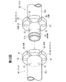
ソケットとプラグとを用いた継手部材の従来例について第5図及び第6図を参照して説明する。 A conventional example of a joint member using a socket and a plug will be described with reference to FIGS.
ユニットルームの壁パネル1に設けられた壁貫通継手2Aのカウンター内側の端部は、フランジ16を有したソケット15となっている。金属製の蛇腹状のフレキ管(ホース)7Aの両端には、フランジ17付きのプラグ18がカシメカラー19を介して固着されている。このプラグ18の外周にOリング20が装着されている。
The end portion inside the counter of the wall penetration joint 2 </ b> A provided on the wall panel 1 of the unit room is a socket 15 having a flange 16.
このプラグ18をソケット15に挿入してフランジ16,17を当接させ、クランプ21を外嵌させることによりフレキ管7Aの一端と壁貫通継手2Aとが連結される。
The
このクランプ21は、1対のアーム22を有した略Ω字形状のものであり、アーム22にはフランジ16,17を受け入れる窓孔23が設けられている。このクランプ21は金属製であり、アーム22,22同士は互いに接近・離反方向に弾性変形可能となっている。
The clamp 21 has a substantially Ω-shape having a pair of
カウンター前板9に取り付けられた壁貫通継手10Aのカウンター内側の端部もフランジ25を有したソケット26となっている。このソケット26にフレキ管7Aの他端側のプラグ18が挿入され、クランプ21が外嵌されることにより壁貫通継手10Aとフレキ管7Aの他端とが連結される。
The end portion inside the counter of the wall penetration joint 10 </ b> A attached to the counter front plate 9 is also a socket 26 having a flange 25. The
このようなソケットとプラグとを備えた継手部材においては、ソケットはその軸心回りに回動自在となっている。 In the joint member provided with such a socket and a plug, the socket is rotatable around its axis.
このようにソケットが回動(自転)自在であると、ソケットに連結されたフレキ管(ホース)を所定方向に向けておくことができないという不便が生じることがある。 When the socket is freely rotatable (rotated) in this way, there may be an inconvenience that the flexible pipe (hose) connected to the socket cannot be directed in a predetermined direction.
例えば、後述の実施の形態では、プラグのフレキ管接続筒部(プラグ本体部)がく字形に屈曲しており、フレキ管を該筒部先端側の軸心線方向に延在させるようにしているが、プラグが自転自在であると、フレキ管接続筒部先端側の方向は、プラグの自転に伴って変化する。 For example, in the embodiments described later, the flexible tube connecting tube portion (plug main body portion) of the plug is bent in a square shape, and the flexible tube extends in the axial direction on the distal end side of the tube portion. However, if the plug can rotate freely, the direction of the flexible tube connecting tube portion tip side changes as the plug rotates.
プラグをソケットに対し自転不能に係合させるために、プラグ側のフランジとソケット側のフランジの一方に凸部を設け、他方に凹部を設け、これら凸部と凹部とを係合させる構造が特開平8−296777号公報に記載されている。
上記特開平8−296777号公報の継手部材にあっては、プラグをソケットに差し込んで両者のフランジが重なると、その段階でプラグ側フランジとソケット側フランジとが凹凸係合してプラグが自転不能となる。このため、プラグをソケットに深く差し込んで両者のフランジ同士を重ねた後は、クランプ装着前であってもプラグを回してその向きを調整することができない。 In the joint member disclosed in Japanese Patent Laid-Open No. 8-296777, when the plug is inserted into the socket and both flanges overlap, the plug side flange and the socket side flange engage with each other at that stage so that the plug cannot rotate. It becomes. For this reason, after the plug is inserted deeply into the socket and the flanges are overlapped with each other, the orientation cannot be adjusted by turning the plug even before the clamp is mounted.
本発明は、このような従来技術の問題点を解決し、プラグをソケットに両者のフランジ同士が重なるまで差し込んだ後も、両者のフランジが重なったままでプラグを回して向きを調整することができる継手部材を提供することを目的とする。 The present invention solves such problems of the prior art, and even after the plug is inserted into the socket until both flanges overlap each other, the orientation can be adjusted by turning the plug while the both flanges overlap. An object is to provide a joint member.
本発明(請求項1)の継手部材は、プラグ差込孔を有すると共に端部に第1のフランジが設けられたソケットと、該プラグ差込孔に差し込まれる筒体部及び前記第1のフランジに重なる第2のフランジを有したプラグと、重なり合った第1のフランジ及び第2のフランジに係合し、両者の離反を阻止するクランプとを有する継手部材において、該第1及び第2のフランジには、周面から切り欠かれた形状の凹部が設けられ、該第1及び第2のフランジの少なくとも一方には、周方向に間隔をおいて該凹部が複数個設けられており、前記クランプには、第1のフランジの凹部と第2のフランジの凹部とに係合して両者の周方向の相対的回転を阻止するストッパ部が設けられていることを特徴とするものである。 The joint member of the present invention (Claim 1) includes a socket having a plug insertion hole and having a first flange at an end thereof, a cylindrical body portion inserted into the plug insertion hole, and the first flange. In a joint member having a plug having a second flange that overlaps with the first flange and a clamp that engages with the first flange and the second flange that overlap each other and prevents the two from separating from each other, the first and second flanges Is provided with a recess having a shape cut out from the peripheral surface, and at least one of the first and second flanges is provided with a plurality of recesses in the circumferential direction. Is provided with a stopper portion that engages with the concave portion of the first flange and the concave portion of the second flange to prevent relative rotation of both in the circumferential direction.
請求項2の継手部材は、請求項1において、該第1のフランジ及び第2のフランジの双方に、周方向に同一間隔をおいて複数の凹部が設けられていることを特徴とするものである。 A joint member according to a second aspect is characterized in that, in the first aspect, the first flange and the second flange are provided with a plurality of recesses at the same interval in the circumferential direction. is there.
本発明の継手部材にあっては、ソケット側フランジの凹部とプラグ側フランジの凹部とに対しクランプのストッパ部が係合することにより、プラグとソケットとの相対回転が不能となる。従って、プラグをソケットに対し両者のフランジが重なるまで差し込んだ状態であっても、クランプを装着する前はプラグとソケットとを相対回転させ、向きを調整することができる。このように向き調整を行った後にクランプを装着することにより、所望の向きとした状態にてプラグとソケットを繋ぐことができる。 In the joint member of the present invention, when the stopper portion of the clamp is engaged with the concave portion of the socket side flange and the concave portion of the plug side flange, relative rotation between the plug and the socket becomes impossible. Accordingly, even when the plug is inserted into the socket until both flanges overlap, the orientation of the plug and the socket can be adjusted relative to each other before the clamp is mounted. By attaching the clamp after adjusting the orientation in this way, the plug and the socket can be connected in a desired orientation.
なお、請求項2の継手部材にあっては、複数箇所にて各フランジの凹部同士が重なり合うようになるので、クランプを装着し易いものとなる。 In the joint member according to the second aspect, since the concave portions of the flanges overlap each other at a plurality of locations, the clamp can be easily attached.
以下、図面を参照して本発明の実施の形態について説明する。 Embodiments of the present invention will be described below with reference to the drawings.
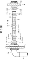
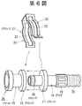
第1図は実施の形態に係る継手部材の側面図、第2図はこの継手部材のプラグとソケットとの分解斜視図、第3図は第1図のIII−III線に沿う断面図であり、第4図はこの継手部材のクランプの斜視図である。 1 is a side view of a joint member according to an embodiment, FIG. 2 is an exploded perspective view of a plug and a socket of the joint member, and FIG. 3 is a cross-sectional view taken along line III-III in FIG. FIG. 4 is a perspective view of the clamp of the joint member.
第1図に示すように、この実施の形態では、継手部材30を介して水栓31にフレキ管32が接続されている。この継手部材30は、プラグ差込孔41(第3図)を有すると共に端部に第1のフランジ42が設けられたソケット40と、該プラグ差込孔41に差し込まれる筒体部51(第2図)及び前記第1のフランジ42に重なる第2のフランジ52を有したプラグ50と、重なり合った第1のフランジ42及び第2のフランジ52に係合し、両者の離反を阻止するクランプ60とを備えている。この実施の形態では、水栓31に該ソケット40が設けられ、フレキ管32の先端にプラグ50が連結されている。
As shown in FIG. 1, in this embodiment, a flexible pipe 32 is connected to a
第2図に示すように、ソケット40及びプラグ50は、それぞれ、略円筒形状の本体部40a,50aを有している。該ソケット40の本体部40aは水栓31と一体に設けられ、その軸心線方向一端(基端)側が該水栓31に連なっている。また、プラグ50の本体部50aは、その軸心線方向一端(基端)側がカシメカラー33を介してフレキ管32の先端に連結されている。
As shown in FIG. 2, the
なお、この実施の形態では、第1図の通り、水栓31は斜め上下方向に延在しており、ソケット40の本体部40aは、その軸心線方向が水栓31の延在方向に対し直角且つ斜め下向きとなるように該水栓31の側面から延出している。また、プラグ50の本体部50aは、図示の通り、その軸心線方向の途中部分からく字形に屈曲している。
In this embodiment, as shown in FIG. 1, the
このソケット40の本体部40aの先端面に、該本体部40aと同心状にプラグ差込孔41が設けられている。また、プラグ50の本体部50aの先端面から、該本体部50aの先端側(く字形屈曲部よりも先端面側)と同軸状に、該プラグ差込孔41に差し込まれる筒体部51が突設されている。符号51aは、この筒体部51の外周に装着されたOリング(止水リング)を示している。該筒体部51は、プラグ差込孔41に対し、その軸心線回りに回動(自転)自在に差し込まれる。
A plug insertion hole 41 is provided concentrically with the
第1のフランジ42と第2のフランジ52とは、それぞれ、該本体部40a,50aの先端面と面一状に、該本体部40a,50aの側周面から放射方向へ延出している。従って、筒体部51をプラグ差込孔41に根元まで差し込むと、該本体部40a,50aの先端面同士が突き合わされ、これら第1のフランジ42と第2のフランジ52とが重なり合う。
The
第1のフランジ42と第2のフランジ52とには、各々の外周面から求心方向へ切り欠いた形状の凹部43,53が設けられている。該凹部43,53同士は、フランジ42,52同士を重なり合わせたときに、相互に連通しうるようになっている。該凹部43,53は、相互に連通した状態において、後述のクランプ60の突起状ストッパ部63が係合可能なものとなっている。この実施の形態では、第1のフランジ42と第2のフランジ52の双方に、各々の周方向に等間隔にて6個ずつ凹部43,53が設けられている。
The
クランプ60は、第3図及び第4図に示すように、ソケット40及びプラグ50の各本体部40a,50aの側周面に沿うように湾曲した1対のアーム部61,61と、該アーム部61,61同士をつなぐ連結部62等を有する略々Ω字形のものである。各アーム部61には、重なり合った第1のフランジ42と第2のフランジ52とを受け入れて両者の離反を阻止する窓孔61aが設けられている。また、連結部62には、相互に連通した第1のフランジ42の凹部43と第2のフランジ52の凹部53とに係合して該フランジ42,52同士の周方向への相対的回転を阻止するストッパ部63が設けられている。
As shown in FIGS. 3 and 4, the clamp 60 includes a pair of arm portions 61, 61 that are curved along the side peripheral surfaces of the
なお、これらのアーム部61,61と連結部62とは弾性を有する金属板等により一連一体に形成されており、該アーム部61,61同士は、互いに接近・離反方向へ弾性変形可能となっている。 The arm portions 61 and 61 and the connecting portion 62 are integrally formed of a metal plate having elasticity and the like, and the arm portions 61 and 61 can be elastically deformed toward and away from each other. ing.
各アーム部61の先端には、重なり合ったフランジ42,52にこのクランプ60を被着するに当って該アーム部61,61同士の弾性的な離反(拡開)を誘導するガイド片61bが設けられている。このガイド片61bは、各アーム部61の先端側を外方(各アーム部61の湾曲中心側へ向う方向(求心方向)と反対方向)へ折曲してなるものである。
At the tip of each arm portion 61, there is provided a
連結部62は、第3図及び第4図に示すように、各本体部40a,50aの側周面から離反する方向(放射方向)へ膨出するように凸形に折曲されている。図示の通り、この連結部62の膨出高さは、各本体部40a,50aの側周面からの各フランジ42,52の突出高さよりも大きなものとなっており、クランプ60が該フランジ42,52に被着された状態にあっては、この連結部62の膨出方向先端部が各フランジ42,52の外周面に覆い被さるようになる。この連結部62の該膨出方向先端部の内側面から求心方向に向って、相互に連通した第1のフランジ42の凹部43と第2のフランジ52の凹部53とに喰い込むように突起状のストッパ部63が突設されている。
As shown in FIGS. 3 and 4, the connecting portion 62 is bent into a convex shape so as to bulge in a direction (radial direction) away from the side peripheral surfaces of the
なお、この実施の形態では、図示の通り、各アーム部61の途中部分にも、放射方向へ向って凸形に折曲された膨出部61cが形成されている。この膨出部61cの膨出高さも、各本体部40a,50aからの各フランジ42,52の突出高さよりも大きなものとなっている。
In this embodiment, as shown in the figure, a bulging
前記窓孔61aは、第4図に示すように、連結部62の側面から該膨出部61cの該連結部62側の側面にかけて延設されると共に、該膨出部61cのアーム部先端側の側面からガイド片61bの基端部にかけて延設されている。
As shown in FIG. 4, the
このように構成された継手部材30を介して水栓31とフレキ管32とを接続するに当っては、まず、プラグ50の筒体部51をソケット40のプラグ差込孔41に差し込みつつ、第1のフランジ42と第2のフランジ52とを重ね合わせる。そして、両フランジ42,52同士を重ね合わせたままプラグ50を回転させ、該プラグ50が所定の向きとなるようにする。この際、第1のフランジ42の凹部43と第2のフランジ52の凹部53とが相互に連通するように両者の位相を一致させる。
In connecting the
なお、この実施の形態では、第1図の通り、プラグ50は、フレキ管32が略鉛直下方に延在するように、即ち、該プラグ50の本体部50aの基端側(く字形屈曲部よりもフレキ管32側)の軸心線方向が略鉛直下方に向う方向となるように向きを調整する。
In this embodiment, as shown in FIG. 1, the plug 50 is arranged so that the flexible pipe 32 extends substantially vertically downward, that is, the base end side of the
その後、重なり合った第1のフランジ42と第2のフランジ52とにクランプ60を被着する。この際、重なり合った第1のフランジ42と第2のフランジ52とが各アーム部61の窓孔61a内に係合し、両者の離反が阻止されるようになると共に、相互に連通した第1のフランジ42の凹部43と第2のフランジ52の凹部53とにストッパ部63が係合し、両者の周方向への相対的回転が阻止されるようになる。これにより、ソケット40とプラグ50とが分離不能に且つ相対的回転不能に連結される。
Thereafter, the clamp 60 is attached to the overlapping
この継手部材30にあっては、上記の通り、第1のフランジ42と第2のフランジ52とが重なるまでプラグ50をソケット40に差し込んだ後も、該フランジ42,52同士を重ね合わせたままでプラグ50を回転させて向きを調整することができる。そして、このように向きを調整した後にクランプ60を装着することにより、プラグ50を所望の向きとした状態にて該プラグ50とソケット40とを連結することができる。
In this joint member 30, as described above, the
この実施の形態では、第1のフランジ42と第2のフランジ52とにそれぞれ6個ずつ、各々の周方向に等間隔にて(互いに同一間隔にて)設けられているので、複数箇所(計6箇所)で凹部43,53同士が重なり合うようになる。このため、クランプ60を装着し易いものとなっている。
In this embodiment, six each of the
なお、上記の実施の形態は本発明の一例を示すものであり、本発明は上記の実施の形態に限定されるものではない。例えば、上記の実施の形態では第1のフランジと第2のフランジの双方に6個ずつ等間隔に凹部を設けているが、各フランジに設けられる凹部の個数並びに配置はこれに限定されるものではない。 In addition, said embodiment shows an example of this invention and this invention is not limited to said embodiment. For example, in the above embodiment, six recesses are provided at equal intervals in both the first flange and the second flange, but the number and arrangement of the recesses provided in each flange is limited to this. is not.
30 継手部材
31 水栓
32 フレキ管
40 ソケット
41 プラグ差込孔
42 第1のフランジ
43 凹部
50 プラグ
51 筒体部
52 第2のフランジ
53 凹部
60 クランプ
61 アーム部
61a 窓孔
62 連結部
63 ストッパ部
DESCRIPTION OF SYMBOLS 30
Claims (2)
該プラグ差込孔に差し込まれる筒体部及び前記第1のフランジに重なる第2のフランジを有したプラグと、
重なり合った第1のフランジ及び第2のフランジに係合し、両者の離反を阻止するクランプと
を有する継手部材において、
該第1及び第2のフランジには、周面から切り欠かれた形状の凹部が設けられ、
該第1及び第2のフランジの少なくとも一方には、周方向に間隔をおいて該凹部が複数個設けられており、
前記クランプには、第1のフランジの凹部と第2のフランジの凹部とに係合して両者の周方向の相対的回転を阻止するストッパ部が設けられていることを特徴とする継手部材。 A socket having a plug insertion hole and provided with a first flange at the end;
A plug having a cylindrical portion inserted into the plug insertion hole and a second flange overlapping the first flange;
In a joint member having a clamp that engages with the first flange and the second flange that overlap each other and prevents the two from separating.
The first and second flanges are provided with recesses in a shape cut out from the peripheral surface,
At least one of the first and second flanges is provided with a plurality of recesses at intervals in the circumferential direction.
The clamp is provided with a stopper portion that engages with the concave portion of the first flange and the concave portion of the second flange to prevent relative rotation of both in the circumferential direction.
Priority Applications (1)
| Application Number | Priority Date | Filing Date | Title |
|---|---|---|---|
| JP2004110172A JP2005291440A (en) | 2004-04-02 | 2004-04-02 | Joint member |
Applications Claiming Priority (1)
| Application Number | Priority Date | Filing Date | Title |
|---|---|---|---|
| JP2004110172A JP2005291440A (en) | 2004-04-02 | 2004-04-02 | Joint member |
Publications (1)
| Publication Number | Publication Date |
|---|---|
| JP2005291440A true JP2005291440A (en) | 2005-10-20 |
Family
ID=35324588
Family Applications (1)
| Application Number | Title | Priority Date | Filing Date |
|---|---|---|---|
| JP2004110172A Pending JP2005291440A (en) | 2004-04-02 | 2004-04-02 | Joint member |
Country Status (1)
| Country | Link |
|---|---|
| JP (1) | JP2005291440A (en) |
Cited By (3)
| Publication number | Priority date | Publication date | Assignee | Title |
|---|---|---|---|---|
| KR20140074224A (en) * | 2012-12-07 | 2014-06-17 | 보스 오토모티브 게임베하 | Plug-in connector for fluid lines |
| JP2017072169A (en) * | 2015-10-06 | 2017-04-13 | 三菱電機株式会社 | Piping connection joint |
| JP2019052722A (en) * | 2017-09-15 | 2019-04-04 | 株式会社清水合金製作所 | Telescopic flexible joint structure and earthquake-proof repair valve |
-
2004
- 2004-04-02 JP JP2004110172A patent/JP2005291440A/en active Pending
Cited By (5)
| Publication number | Priority date | Publication date | Assignee | Title |
|---|---|---|---|---|
| KR20140074224A (en) * | 2012-12-07 | 2014-06-17 | 보스 오토모티브 게임베하 | Plug-in connector for fluid lines |
| JP2014114960A (en) * | 2012-12-07 | 2014-06-26 | Voss Automotive Gmbh | Plug-in connector for fluid conduit |
| KR102189767B1 (en) * | 2012-12-07 | 2020-12-11 | 보스 오토모티브 게임베하 | Plug-in connector for fluid lines |
| JP2017072169A (en) * | 2015-10-06 | 2017-04-13 | 三菱電機株式会社 | Piping connection joint |
| JP2019052722A (en) * | 2017-09-15 | 2019-04-04 | 株式会社清水合金製作所 | Telescopic flexible joint structure and earthquake-proof repair valve |
Similar Documents
| Publication | Publication Date | Title |
|---|---|---|
| JP4092295B2 (en) | Quick release fitting | |
| JP4299646B2 (en) | Pipe fitting | |
| AU2010261529B2 (en) | Push-fit pipe fitting system with support sleeve | |
| JPH10148291A (en) | Joint device connecting two circular tube members | |
| CN114729720A (en) | Pipe fittings and method of assembling pipe fittings for receiving, retaining and releasing pipes | |
| JP2006242383A (en) | Rotation stopping quick connector | |
| JP5091849B2 (en) | Pipe fitting | |
| JP2005291440A (en) | Joint member | |
| JP4733685B2 (en) | Connection structure between tubular connecting member and joint member | |
| JP2009144755A (en) | Pipe joint with anti-rotation function | |
| EP3018394B1 (en) | Universal rotary pipe connector | |
| JP3808870B2 (en) | Tube connection structure | |
| JP2011122698A (en) | Housing type pipe joint | |
| JP5721392B2 (en) | Pipe fitting | |
| CN217130643U (en) | Direct insertion type water inlet bridging component | |
| JP4979652B2 (en) | Method of connecting rubber ring joints of ribbed pipes, ribbed pipes and sewer pipes | |
| JP7498655B2 (en) | Pipe bending control structure between joints, and joint device | |
| JP3146224U (en) | Connection structure of air supply / exhaust pipe | |
| JP4896862B2 (en) | Pipe fitting with connection angle correction function | |
| JP3479136B2 (en) | Pipe fittings | |
| JP4596983B2 (en) | Rib pipe fittings | |
| JP2009005429A (en) | Protection tube connector | |
| JP4693543B2 (en) | Shell tube connecting member | |
| JP4564915B2 (en) | Connection branch | |
| JP2005240345A (en) | Offset fitting |