JP2005291376A - Parking brake device - Google Patents
Parking brake device Download PDFInfo
- Publication number
- JP2005291376A JP2005291376A JP2004107501A JP2004107501A JP2005291376A JP 2005291376 A JP2005291376 A JP 2005291376A JP 2004107501 A JP2004107501 A JP 2004107501A JP 2004107501 A JP2004107501 A JP 2004107501A JP 2005291376 A JP2005291376 A JP 2005291376A
- Authority
- JP
- Japan
- Prior art keywords
- parking
- piston
- brake
- lock
- hydraulic pressure
- Prior art date
- Legal status (The legal status is an assumption and is not a legal conclusion. Google has not performed a legal analysis and makes no representation as to the accuracy of the status listed.)
- Granted
Links
Images

Classifications
-
- F—MECHANICAL ENGINEERING; LIGHTING; HEATING; WEAPONS; BLASTING
- F16—ENGINEERING ELEMENTS AND UNITS; GENERAL MEASURES FOR PRODUCING AND MAINTAINING EFFECTIVE FUNCTIONING OF MACHINES OR INSTALLATIONS; THERMAL INSULATION IN GENERAL
- F16D—COUPLINGS FOR TRANSMITTING ROTATION; CLUTCHES; BRAKES
- F16D65/00—Parts or details
- F16D65/14—Actuating mechanisms for brakes; Means for initiating operation at a predetermined position
- F16D65/16—Actuating mechanisms for brakes; Means for initiating operation at a predetermined position arranged in or on the brake
- F16D65/22—Actuating mechanisms for brakes; Means for initiating operation at a predetermined position arranged in or on the brake adapted for pressing members apart, e.g. for drum brakes
-
- F—MECHANICAL ENGINEERING; LIGHTING; HEATING; WEAPONS; BLASTING
- F16—ENGINEERING ELEMENTS AND UNITS; GENERAL MEASURES FOR PRODUCING AND MAINTAINING EFFECTIVE FUNCTIONING OF MACHINES OR INSTALLATIONS; THERMAL INSULATION IN GENERAL
- F16D—COUPLINGS FOR TRANSMITTING ROTATION; CLUTCHES; BRAKES
- F16D2121/00—Type of actuator operation force
- F16D2121/02—Fluid pressure
-
- F—MECHANICAL ENGINEERING; LIGHTING; HEATING; WEAPONS; BLASTING
- F16—ENGINEERING ELEMENTS AND UNITS; GENERAL MEASURES FOR PRODUCING AND MAINTAINING EFFECTIVE FUNCTIONING OF MACHINES OR INSTALLATIONS; THERMAL INSULATION IN GENERAL
- F16D—COUPLINGS FOR TRANSMITTING ROTATION; CLUTCHES; BRAKES
- F16D2127/00—Auxiliary mechanisms
- F16D2127/06—Locking mechanisms, e.g. acting on actuators, on release mechanisms or on force transmission mechanisms
-
- F—MECHANICAL ENGINEERING; LIGHTING; HEATING; WEAPONS; BLASTING
- F16—ENGINEERING ELEMENTS AND UNITS; GENERAL MEASURES FOR PRODUCING AND MAINTAINING EFFECTIVE FUNCTIONING OF MACHINES OR INSTALLATIONS; THERMAL INSULATION IN GENERAL
- F16D—COUPLINGS FOR TRANSMITTING ROTATION; CLUTCHES; BRAKES
- F16D2129/00—Type of operation source for auxiliary mechanisms
- F16D2129/02—Fluid-pressure
Landscapes
- Engineering & Computer Science (AREA)
- General Engineering & Computer Science (AREA)
- Mechanical Engineering (AREA)
- Braking Arrangements (AREA)
Abstract
【課題】電力消費を伴わない簡単な構造で自動パーキングブレーキ状態を得ることができるようにする。
【解決手段】パーキング用制御液圧の作用に応じたパーキングピストン33の前進作動によってパーキングブレーキ状態が得られ、パーキングピストン33の前進状態がロック機構43で機械的にロックされる。しかもブレーキ機構11の入力部材23およびパーキングピストン33間が連結手段35で連結され、ロック機構43が備えるロックピストン44が、パーキングピストン33の前進作動時には軸方向一方に作動し、ロックピストン44の一端に設けられるロック部46が連結手段35の中間部を跨ぎつつ該連結手段35の中間部に設けられている係止部45に後方から係合する。
【選択図】 図3An automatic parking brake state can be obtained with a simple structure without power consumption.
A parking brake state is obtained by a forward operation of a parking piston according to the action of a control fluid pressure for parking, and the forward state of the parking piston is mechanically locked by a lock mechanism. Moreover, the input member 23 of the brake mechanism 11 and the parking piston 33 are connected by the connecting means 35, and the lock piston 44 provided in the lock mechanism 43 operates in one axial direction when the parking piston 33 moves forward, and one end of the lock piston 44 A locking portion 46 provided on the intermediate portion engages with a locking portion 45 provided at the intermediate portion of the connecting means 35 from behind while straddling the intermediate portion of the connecting means 35.
[Selection] Figure 3
Description
本発明は、パーキングブレーキ装置に関し、特に、液圧の作用によってパーキングブレーキ状態を得るようにしたパーキングブレーキ装置に関する。 The present invention relates to a parking brake device, and more particularly to a parking brake device that obtains a parking brake state by the action of hydraulic pressure.
このようなパーキングブレーキ装置は、たとえば特許文献1および特許文献2等で既に知られている。
ところで、上記特許文献1では、ブレーキピストンが、前部および後部ブレーキピストンに分割されるとともに、後部ブレーキピストンの前端に当接する伝達部材と、前部ブレーキピストンに固定される閉塞板との間にばねが縮設され、前部ブレーキピストンの後方でブレーキキャリパの内面に刻設される内歯に噛合し得るラッチが、前記伝達部材が後部ブレーキピストンの前端に当接した状態では内歯に係合するものの伝達部材が後部ブレーキピストンの前端から前方に相対移動移動したときにはばね付勢力で内歯との係合を解除するようにしてブレーキキャリパ内に収納され、前記後部ブレーキピストンには、伝達部材を後部ブレーキピストンに対して軸方向に相対移動させ得る補助ピストンが摺動自在に嵌合されている。しかるにブレーキキャリパの内面に内歯を刻設せねばならず、またブレーキピストンを前部および後部ブレーキピストンに分割しつつラッチをブレーキキャリパ内に収納するようにしているので、ブレーキキャリパ内の構造が複雑となる。 By the way, in the said patent document 1, while a brake piston is divided | segmented into a front part and a rear brake piston, between the transmission member contact | abutted to the front end of a rear brake piston, and the obstruction board fixed to a front brake piston. A latch that can be engaged with an internal tooth engraved on the inner surface of the brake caliper behind the front brake piston with a spring contracted is engaged with the internal tooth when the transmission member is in contact with the front end of the rear brake piston. However, when the transmission member moves relatively forward from the front end of the rear brake piston, it is accommodated in the brake caliper so as to be disengaged from the inner teeth by a spring biasing force, and is transmitted to the rear brake piston. An auxiliary piston that can move the member in the axial direction relative to the rear brake piston is slidably fitted. However, internal teeth must be engraved on the inner surface of the brake caliper, and the latch is housed in the brake caliper while dividing the brake piston into the front and rear brake pistons. It becomes complicated.
また上記特許文献2では、ブレーキピストンに前端部が固定的に連結される調整ボルトに調整ナットが螺合され、この調整ナットをケーシングに摩擦係合させる電磁力を発揮する電磁石が前記調整ナットの後方でブレーキキャリパ内に配設されており、パーキングブレーキ状態を得るときには、ブレーキ液圧をブレーキピストンに作用せしめた状態で前記電磁石により調整ナットをケーシングに摩擦係合させることにより、ブレーキピストンの後退を阻止するようにしている。しかるに電磁石をブレーキキャリパ内に収納させる必要があり、構造が複雑となるだけでなく、パーキングブレーキ状態では電磁石の巻線への通電状態を維持する必要があるので、消費電力量が多くなる。
Further, in
本発明は、かかる事情に鑑みてなされたものであり、電力消費を伴わない簡単な構造でパーキングブレーキ状態を得ることができるようにしたパーキングブレーキ装置を提供することを目的とする。 The present invention has been made in view of such circumstances, and an object of the present invention is to provide a parking brake device that can obtain a parking brake state with a simple structure that does not involve power consumption.
上記目的を達成するために、本発明は、入力部材への入力に応じてパーキング作動するブレーキ機構と、背面側へのパーキング用制御液圧の作用に応じた前進作動するようにしてケーシングに摺動可能に嵌合されるパーキングピストンと、該パーキングピストンの前進作動に応じて前記ブレーキ機構をパーキング作動せしめるようにして前記入力部材および前記パーキングピストン間を連結する連結手段と、前記パーキングピストンを前進位置で機械的にロックすべく前記パーキングピストンの前進作動に応じて自動的にロック作動するとともにパーキング解除用制御液圧の作用に応じてロック解除作動するようにして前記ケーシング内に設けられるロック機構と、液圧発生源と、該液圧発生源の発生液圧を制御して前記パーキング用制御液圧および前記パーキング解除用制御液圧を得ることを可能とした液圧制御手段とを含み、前記ロック機構は、少なくとも前記パーキングピストンの前進作動時には軸方向一方に向けての付勢力が作用するようにしつつ前記パーキングピストンの軸線と直交する軸線を有して前記ケーシングに摺動可能に嵌合されるとともにパーキング解除用制御圧を軸方向他方に向けて作用せしめることを可能としたロックピストンと、前記連結手段の中間部に設けられる係止部と、該係止部に後方から係合して前記パーキングピストンの前進作動位置を機械的にロックすべく前記ロックピストンの軸方向一端部に設けられるロック部とを備え、該ロック部は、前記パーキングピストンの前進位置では前記連結手段の中間部を跨いで前記係止部に係合するように形成されることを特徴とする。 In order to achieve the above object, the present invention provides a brake mechanism that operates in accordance with an input to an input member, and a sliding mechanism that slides on a casing so as to operate forward in response to the action of a control hydraulic pressure for parking on the back side. A parking piston that is movably fitted, a coupling means that couples the input member and the parking piston so as to park the brake mechanism in accordance with the forward movement of the parking piston, and forwards the parking piston. Lock mechanism provided in the casing so as to automatically lock in accordance with the forward movement of the parking piston and mechanically lock in accordance with the operation of the parking release control hydraulic pressure to mechanically lock in position. And a parking pressure control liquid by controlling the generated hydraulic pressure of the hydraulic pressure generation source and the hydraulic pressure generation source. And a hydraulic pressure control means that makes it possible to obtain the parking release control hydraulic pressure, and the locking mechanism is configured to apply an urging force in one axial direction at least when the parking piston moves forward. While having an axis orthogonal to the axis of the parking piston, the lock piston is slidably fitted to the casing and allows the parking release control pressure to act in the other axial direction, A locking portion provided at an intermediate portion of the coupling means, and a lock provided at one axial end portion of the lock piston so as to mechanically lock the forward operation position of the parking piston by engaging with the locking portion from behind. And the locking portion is engaged with the locking portion across the intermediate portion of the connecting means at the forward position of the parking piston. Characterized in that it is formed.
本発明によれば、パーキングピストンの背面側にパーキング用制御液圧を作用させると、パーキングピストンが前進するとともにロック機構がパーキングピストンの前進位置を機械的にロックするので、パーキングブレーキ状態を自動的に得ることができ、またパーキングブレーキ状態を解除するときには、パーキング解除用制御液圧をロック機構に作用せしめればよく、パーキングブレーキ状態では電力消費を伴わない簡単な構造でパーキングブレーキ状態を自動的に得ることができる。 According to the present invention, when the parking control hydraulic pressure is applied to the back side of the parking piston, the parking piston moves forward and the lock mechanism mechanically locks the advance position of the parking piston. When releasing the parking brake state, it is only necessary to apply the parking release control hydraulic pressure to the lock mechanism. In the parking brake state, the parking brake state is automatically set with a simple structure that does not involve power consumption. Can get to.
またブレーキ機構の入力部材およびパーキングピストン間が連結手段で連結されており、ロック機構が備えるロックピストンが、パーキングピストンの前進作動時には軸方向一方に作動し、ロックピストンの一端に設けられるロック部が前記連結手段の中間部を跨ぎつつ該連結手段の中間部に設けられている係止部に後方から係合するので、パーキングピストンの前進作動力をブレーキ機構の入力部材に連結手段を介して伝達するように構成した上で、ロック機構のコンパクト化および簡素化を図ることができる。 In addition, the input member of the brake mechanism and the parking piston are connected by a connecting means, and the lock piston provided in the lock mechanism operates in one axial direction when the parking piston moves forward, and a lock portion provided at one end of the lock piston is provided. Since the engaging portion provided at the intermediate portion of the connecting means is engaged from behind while straddling the intermediate portion of the connecting means, the forward operating force of the parking piston is transmitted to the input member of the brake mechanism via the connecting means. In addition, the lock mechanism can be made compact and simple.
以下、本発明の実施の形態を、添付の図面に示した本発明の一実施例に基づいて説明する。 DESCRIPTION OF THE PREFERRED EMBODIMENTS Embodiments of the present invention will be described below based on one embodiment of the present invention shown in the accompanying drawings.
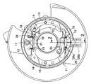
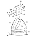
図1〜図9は本発明の一実施例を示すもので、図1はドラムブレーキの正面図、図2は図1の2−2線拡大断面図、図3は図2の3−3線断面図、図4は図3の4矢視図、図5はストッパおよびロックピストンの斜視図、図6は液圧回路の構成を示す図、図7はパーキングブレーキ状態での図2に対応した断面図、図8は図7の8−8線断面図、図9は図8の9−9線断面図である。 1 to 9 show an embodiment of the present invention, FIG. 1 is a front view of a drum brake, FIG. 2 is an enlarged sectional view taken along line 2-2 of FIG. 1, and FIG. 3 is a line 3-3 of FIG. FIG. 4 is a perspective view of the stopper and the lock piston, FIG. 6 is a diagram showing the configuration of the hydraulic circuit, and FIG. 7 corresponds to FIG. 2 in the parking brake state. 8 is a cross-sectional view taken along line 8-8 in FIG. 7, and FIG. 9 is a cross-sectional view taken along line 9-9 in FIG.
先ず図1において、パーキングブレーキ専用のブレーキ機構であるドラムブレーキ11が備えるバックプレート12は、図示しないブレーキドラムの開放端を覆うようにして車体側に固定的に取付けられる。前記ブレーキドラムに摺接し得るライニング14,14を有してブレーキドラム内に配置される一対のブレーキシュー13,13の一端は伸縮調節可能なストラット15の両端に揺動可能に支承され、両ブレーキシュー13…の一端間には前記ストラット15の両端側に両ブレーキシュー13…を付勢するばね16が縮設される。また両ブレーキシュー13…の他端は、前記バックプレート12に設けられたアンカ17に離間可能に支承されるとともに戻しばね18によって前記アンカ17で支承される側に付勢される。また両ブレーキシュー13…の他端側対向面には切欠き19…がそれぞれ設けられており、それらの切欠き19…にストラット21の両端が係合され、ストラット21の一端および一方のブレーキシュー13間にはばね22が縮設される。
First, in FIG. 1, a
一方の前記ブレーキシュー13と一部が重なるようにして入力部材としてのパーキング作動レバー23が前記ブレーキシュー13およびバックプレート12間に配置されており、該作動レバー23の一端にパーキング駆動手段25が連結される。またパーキング作動レバー23の他端部は、前記ストラット21の一端に係合されるとともに一方の前記ブレーキシュー13の他端部に枢軸24を介して揺動可能に連結される。
A parking operation lever 23 as an input member is disposed between the
而して前記パーキング駆動手段25によって前記パーキング作動レバー23を枢軸24のまわりに図1の時計方向に回動せしめると、ストラット21を介して他方のブレーキシュー13がブレーキドラムの内周に圧接され、その反作用によって一方のブレーキシュー13もブレーキドラムの内周に圧接され、それによりドラムブレーキ11によるパーキングブレーキ状態を得ることができる。
Thus, when the
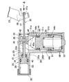
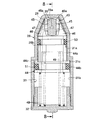
図2および図3を併せて参照して、前記パーキング駆動手段25は、前記両ブレーキシュー13…の一端側でバックプレート12に固定されるケーシング26を備える。該ケーシング26は、前記ストラット15およびばね16と平行な方向に延びる第1筒部26aと、第1筒部26aに直交する方向に延びて第1筒部26aの中間部に一体に連設される第2筒部26bとを備え、バックプレート12の内面側に第1筒部26aが配置され、第2筒部26bは、バックプレート12を貫通して外方に延出される。
2 and 3 together, the parking drive means 25 includes a
両端を開放した第1筒部26aの軸方向中間部には隔壁27が一体に設けられており、隔壁27よりも前側(図3の上側)で第1筒部26aには第1摺動孔28が設けられ、前記隔壁27よりも後側(図3の下側)で第1筒部26a内は第1摺動孔28と同軸のガイド孔29が設けられ、第1摺動孔28の前端を閉じる蓋部材30が第1筒部26aに螺合される。
A
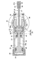
また第2筒部26bには、前記ガイド孔29に直角に連なる第2摺動孔31が設けられ、この第2摺動孔31は、ガイド孔29に一端を連ならせた小径孔部31aと、小径孔部31aよりも大径にして小径孔31aの他端に一端が同軸に連なる大径孔部31bとが同軸に連なって成り、小径孔部31aおよび大径孔部31b間にはガイド孔29と反対側に臨む環状の段部31cが形成され、大径孔部31bの他端を閉じる蓋部材32が第2筒部26bの外端に螺合される。
The second
ケーシング26の第1摺動孔28には、背面側へのパーキング用制御液圧の作用に応じた前進作動によってパーキングブレーキ状態を得ることを可能としたパーキングピストン33が摺動可能に嵌合され、該パーキングピストン33の外周には環状のシール部材40が装着される。このパーキングピストン33の背面および前記隔壁27間でケーシング26の第1筒部26a内に、パーキング用制御液圧を作用させることを可能としたパーキング用制御液圧室34が形成される。
The first sliding
前記パーキングピストン33は、連結手段35を介してドラムブレーキ11におけるパーキング作動レバー23の一端部に連結されており、前記パーキングピストン33の前進作動に応じて連結手段35に作用する牽引力が前記パーキング作動レバー23に入力され、それによりパーキング作動レバー23がドラムブレーキ11をパーキング作動せしめる側に回動することになる。
The
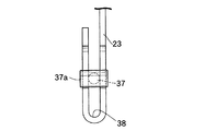
而して前記連結手段35は、環状のシール部材41を介して前記隔壁27を液密にかつ摺動可能に貫通してパーキングピストン33の後端中央部に同軸にかつ一体に連結されるロッド33aと、該ロッド33aに連結されてガイド孔29に摺動可能に嵌合されるストッパ36と、ストッパ36およびパーキング作動レバー23間を連結する連結ロッド37とから成り、前記隔壁27とは反対側でガイド孔29の端部には前記ストッパ36がガイド孔29から外れてしまうのを阻止するための止め輪42が装着される。
Thus, the connecting
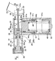
図4を併せて参照して、前記パーキング作動レバー23の一端部はスリット38を形成するようにして略U字状に折り曲げられており、そのスリット38に挿通される前記連結ロッド37の端部に、パーキング作動レバー23の一端部に当接、係合する拡大係合部37aが設けられる。しかも拡大係合部37aを当接、係合せしめるべくパーキング作動レバー23に設けられる当接面39は円弧状のものであり、前記パーキングピストン33の前進作動に伴ってパーキング作動レバー23に作用する牽引力が最大になるときの前記拡大係合部37aの接触点での前記当接面39の接線が、連結ロッド37からパーキング作動レバー23への牽引力作用方向と直角となるだけでなく、連結ロッド37の全ストローク領域で拡大係合部37aの接触点での前記接線が前記牽引力作用方向と直角となるように形成される。
Referring also to FIG. 4, one end portion of the
しかも拡大係合部37aの少なくとも前記当接面39に接触する部分の外面形状は当接面39に向かって凸である曲面状に形成されている。
In addition, the outer surface shape of at least the portion of the enlarged engaging
またケーシング26内には、前記パーキングピストン33を前進位置で機械的にロックすべく該パーキングピストン33の前進作動に応じて自動的にロック作動するとともに、パーキング解除用制御液圧の作用に応じてロック解除作動するロック機構43が設けられる。
Further, in the
このロック機構43は、パーキングピストン33の前進作動時には軸方向一方に向けての付勢力が作用するようにしつつ前記パーキングピストン33の軸線と直交する軸線を有して前記ケーシング26に摺動可能に嵌合されるとともにパーキング解除用制御圧を軸方向他方に向けて作用せしめることを可能としたロックピストン44と、前記パーキングピストン33およびパーキング作動レバー23間を連結する連結手段35の中間部材であるストッパ36に設けられる一対の係止部45,45と、それらの係止部45,45に後方から係合して前記パーキングピストン33の前進作動位置を機械的にロックすべく前記ロックピストン44の軸方向一端部に設けられる一対のロック部46,46とを備える。
The
図5を併せて参照して、前記ストッパ36は、第2摺動孔31およびガイド孔29の軸線と直交する方向の厚みを薄くした略矩形状の横断面形状を有するように形成されており、該ストッパ36の両側に突設された支持ボス47,47にリング状である前記係止部45,45が嵌合、固定される。
Referring also to FIG. 5, the
ロックピストン44は、前記パーキングピストン33よりも後方側に配置される第2摺動孔31に摺動可能に嵌合されるものであり、第2摺動孔31の小径孔部31aに摺動可能に嵌合される小径部44aと、第2摺動孔31の段部31cに対向する環状の段部44cを小径部44aの後部との間に形成して小径部44aに同軸に連なるとともに第2摺動孔31の大径孔部31bに摺動可能に嵌合される大径部44bとを一体に備える。
The
ロックピストン44および蓋部材32間には、ロックピストン44を軸方向一方側すなわちストッパ36側にばね付勢するために、たとえば並列配置される一対のばね48,48が縮設される。またロックピストン44における段部44cおよび第2摺動孔31における段部31c間でロックピストン44およびケーシング26間にはロックピストン44を軸方向他方側に付勢するパーキング解除用制御液圧を作用せしめる環状のパーキング解除用制御液圧室49が形成され、ロックピストン44のパーキング解除用制御液圧室49に臨む受圧面積は、前記パーキングピストン33のパーキング用制御液圧室34に臨む受圧面積よりも大きく設定される。
Between the
またロックピストン44における小径部44aおよび大径部44bの外周には、パーキング解除用制御液圧室49を軸方向両側からシールして第2摺動孔31の小径孔部31aおよび大径孔部31bに摺接する環状のシール部材50,51が装着される。
Further, on the outer periphery of the
ロックピストン44の一端側の小径部44aには、パーキングピストン33の前進位置では前記連結手段35の中間部にあるストッパ36を跨いで係止部45,45に係合するようにしてロック部46,46が一体に設けられており、それらのロック部46,46の外周面は、第2摺動孔31の小径孔部31aよりも小径であるガイド孔29内のストッパ36に係合することを可能として、先端側を細狭まりとしたテーパ状に形成される。
The
しかもロック部46,46には、前記係止部45,45に後方側から係合し得る係合面46a,46aが形成されており、これらの係合面46a…は、前記ロックピストン44の軸方向一方に向かうにつれてパーキングピストン33の軸方向後方位置となるように傾斜している。
Moreover, the
図6において、パーキング用制御液圧室34に作用せしめるパーキング用制御液圧ならびにパーキング解除用制御液圧室49に作用せしめるパーキング解除用制御液圧は、液圧発生源55の発生液圧を液圧制御手段56で制御することにより得られるものであり、この液圧制御手段56は、パーキング用制御液圧室34を液圧発生源55およびリザーバ57に択一的に連通させる状態ならびにパーキング用制御液圧室34の液圧ロック状態を切換可能な第1制御弁58と、パーキング解除用制御液圧室49を液圧発生源55およびリザーバ57に択一的に連通させる状態ならびにパーキング解除用制御液圧室49の液圧ロック状態を切換可能な第2制御弁59とから成る。
In FIG. 6, the parking control hydraulic pressure that acts on the parking control
パーキングブレーキ状態を得るときには、パーキング用制御液圧室34にパーキング用制御液圧を作用させ、さらにパーキング解除用制御液圧室49に液圧を作用させることで、ロックピストン44の軸方向一方への作動を抑えつつ、パーキングピストン33を前進せしめる。次いでパーキング解除用制御液圧室49の液圧を解放すると、ロックピストン44がばね48…のばね力で軸方向一方に作動し、パーキングピストン33およびロックピストン44の前進に応じてロック機構43がロック作動する。
When the parking brake state is obtained, the parking control
すなわち図7〜図9で示すように、パーキングピストン33とともに前進作動したストッパ36の両係止部45,45にロックピストン44の一端のロック部46,46に形成された係合面46a,46aが後方から係合し、パーキングピストン33の前進作動状態が機械的にロックされることになる。但しロックピストン44の軸方向一方への作動が完了した時点でパーキング制御用液圧室34の残圧を抜く。
That is, as shown in FIGS. 7 to 9, the engaging
このようにパーキングピストン33が前進作動すると、パーキング作動レバー23の回動によりドラムブレーキ11がパーキング作動し、パーキングピストン33の前進作動状態がロックされることにより、パーキングブレーキ状態が維持される。しかもドラムブレーキ11において両ブレーキシュー13…をパーキングブレーキのために作動せしめる力はパーキング作動レバー23を介して両ブレーキシュー13,14に伝わるので、パーキング作動レバー23のレバー比により、パーキング駆動手段25が発揮すべき液圧力が比較的小さくてすむ。
When the
パーキングブレーキ状態を解除するときには、パーキング用制御液圧室34およびパーキング解除用制御液圧室49の液圧を同時に増圧せしめるが、その増圧過程で、先ずばね48…のばね力よりも大きな液圧力がロックピストン44に作用することでロックピストン44が軸方向他方側に移動し、それによりロック機構43のロック状態が解除されるので、パーキング用制御液圧室34の液圧によってパーキングピストン33が後退作動する。而してロック機構43のロック解除状態で前記パーキング解除用制御液圧室49は液圧ロック状態に保持され、ロックピストン44のロック部46,46はストッパ36との当接を回避する位置まで移動したままである。
When releasing the parking brake state, the hydraulic pressure in the parking control
次にこの実施例の作用について説明すると、ドラムブレーキ11をパーキングブレーキ作動せしめる際には、パーキング駆動手段25が有するパーキングピストン33の背面側が臨むパーキング用制御液圧室34にパーキング用制御液圧を作用させればよく、パーキングピストン33を前進作動せしめることにより、ドラムブレーキ11をブレーキ作動せしめてパーキングブレーキ状態を得ることが可能となり、またパーキングピストン33の前進作動によるパーキング作動状態がロック機構43で機械的にロックされるので、パーキングブレーキ状態を自動的に得ることができ、またパーキングブレーキ状態を解除するときにはパーキング解除用制御液圧をロック機構43に作用せしめればよく、パーキングブレーキ状態では電力消費を伴わない簡単な構造でパーキングブレーキ状態を自動的に得ることができる。
Next, the operation of this embodiment will be described. When the
またロック機構43は、パーキングピストン33の前進作動時には軸方向一方に向けての付勢力が作用するようにしつつパーキングピストン33の軸線と直交する軸線を有してケーシング26に摺動可能に嵌合されるとともにパーキング解除用制御圧を軸方向他方に向けて作用せしめることを可能としたロックピストン44と、パーキングピストン33に連結されるストッパ36に設けられる係止部45…と、該係止部45…に後方から係合してパーキングピストン33の前進作動位置を機械的にロックする係合面46a…を有してロックピストン44の軸方向一端部に設けられるロック部46…とを備えるものであり、係合面46a…はロックピストン44の軸方向一方に向かうにつれてパーキングピストン33の軸方向後方位置となるように傾斜している。
Further, the
したがってパーキングブレーキ状態でのパーキングピストン33の後退限からの前進移動量の変化に対処してパーキングピストン33の前進作動位置を機械的にロックすることが可能であり、寸法公差、組付け誤差もしくはブレーキシュー13…におけるライニング14…の摩耗に応じたパーキングピストン33のストローク量変化に対応することができる。
Accordingly, it is possible to mechanically lock the forward operation position of the
また前記係止部45…が設けられるストッパ36は、パーキングピストン33およびパーキング作動レバー23間を結ぶ連結手段35の中間に配置されるものであり、前記ロック部46,46はストッパ36を跨ぐようにしてロックピストン44の一端部に設けられるので、パーキングピストン33の前進作動力をドラムブレーキ11のパーキング作動レバー23に連結手段35を介して伝達するように構成した上で、ロック機構43のコンパクト化および簡素化を図ることができる。
Further, the
さらに連結手段35の一部である連結ロッド37の端部に設けられる拡大係合部37aが、パーキング作動レバー23の一端部に当接、係合されるのであるが、拡大係合部37aを当接、係合せしめるべく、パーキング作動レバー23に設けられる円弧状の当接面39は、前記パーキングピストン33の前進作動に伴ってパーキング作動レバー23に作用する牽引力が最大になるときの前記拡大係合部37aの接触点での前記当接面39の接線が、連結ロッド37からパーキング作動レバー23への牽引力作用方向と直角となるだけでなく、連結ロッド37の全ストローク領域で拡大係合部37aの接触点での前記接線が前記牽引力作用方向と直角となるように形成される。
Further, an enlarged
したがってパーキング作動レバー23に作用する牽引力が最大になるときに、連結ロッド37およびパーキング作動レバー23間にこじりが生じるのを抑制し、耐久性の向上を図ることができるだけでなく、連結ロッド37の全ストローク領域で連結ロッド37およびパーキング作動レバー23間にこじりが生じるのを抑制し、耐久性のより一層の向上を図ることができる。
Therefore, when the traction force acting on the
また拡大係合部37aの少なくとも前記当接面39に接触する部分の外面形状が当接面39に向かって凸である曲面状に形成されているので、連結ロッド37およびパーキング作動レバー23間にこじりが生じるのをより効果的に抑制することができ、パーキング作動レバー23および拡大係合部37aの接触面積を比較的大きくして応力緩和を図ることができる。
Further, since the outer surface shape of at least the portion of the enlarged engaging
しかもパーキング作動レバー23に設けられるスリット38の連結ロッド37を挿通せしめることで連結ロッド37をパーキング作動レバー23に係合、連結することができるので組付け性もよい。
Moreover, since the connecting
以上、本発明の実施例を説明したが、本発明は上記実施例に限定されるものではなく、特許請求の範囲に記載された本発明を逸脱することなく種々の設計変更を行うことが可能である。 Although the embodiments of the present invention have been described above, the present invention is not limited to the above-described embodiments, and various design changes can be made without departing from the present invention described in the claims. It is.
11・・・ブレーキ機構としてのドラムブレーキ
23・・・入力部材としてのパーキング作動レバー
26・・・ケーシング
33・・・パーキングピストン
35・・・連結手段
43・・・ロック機構
44・・・ロックピストン
45・・・係止部
46・・・ロック部
55・・・液圧発生源
56・・・液圧制御手段
DESCRIPTION OF
Claims (1)
Priority Applications (6)
| Application Number | Priority Date | Filing Date | Title |
|---|---|---|---|
| JP2004107501A JP4084775B2 (en) | 2004-03-31 | 2004-03-31 | Parking brake device |
| PCT/JP2005/006031 WO2005095817A1 (en) | 2004-03-31 | 2005-03-30 | Parking brake device |
| US10/592,182 US7779972B2 (en) | 2004-03-31 | 2005-03-30 | Parking brake system |
| CNB2005800100723A CN100424374C (en) | 2004-03-31 | 2005-03-30 | Parking brake device |
| DE602005024375T DE602005024375D1 (en) | 2004-03-31 | 2005-03-30 | PARKING BRAKE DEVICE |
| EP05727922A EP1731789B1 (en) | 2004-03-31 | 2005-03-30 | Parking brake device |
Applications Claiming Priority (1)
| Application Number | Priority Date | Filing Date | Title |
|---|---|---|---|
| JP2004107501A JP4084775B2 (en) | 2004-03-31 | 2004-03-31 | Parking brake device |
Publications (2)
| Publication Number | Publication Date |
|---|---|
| JP2005291376A true JP2005291376A (en) | 2005-10-20 |
| JP4084775B2 JP4084775B2 (en) | 2008-04-30 |
Family
ID=35063851
Family Applications (1)
| Application Number | Title | Priority Date | Filing Date |
|---|---|---|---|
| JP2004107501A Expired - Fee Related JP4084775B2 (en) | 2004-03-31 | 2004-03-31 | Parking brake device |
Country Status (6)
| Country | Link |
|---|---|
| US (1) | US7779972B2 (en) |
| EP (1) | EP1731789B1 (en) |
| JP (1) | JP4084775B2 (en) |
| CN (1) | CN100424374C (en) |
| DE (1) | DE602005024375D1 (en) |
| WO (1) | WO2005095817A1 (en) |
Cited By (5)
| Publication number | Priority date | Publication date | Assignee | Title |
|---|---|---|---|---|
| CN105736610A (en) * | 2016-04-22 | 2016-07-06 | 宁波格陆博科技有限公司 | Electronic control actuating mechanism for parking brake |
| JPWO2014203899A1 (en) * | 2013-06-17 | 2017-02-23 | アイシン・エィ・ダブリュ株式会社 | Parking device |
| US9702421B2 (en) | 2013-06-17 | 2017-07-11 | Aisin Aw Co., Ltd. | Parking device |
| US10071714B2 (en) | 2013-06-17 | 2018-09-11 | Aisin Aw Co., Ltd. | Parking device |
| US10648560B2 (en) | 2013-10-23 | 2020-05-12 | Aisin Aw Co., Ltd. | Parking device |
Families Citing this family (12)
| Publication number | Priority date | Publication date | Assignee | Title |
|---|---|---|---|---|
| FR2926859B1 (en) * | 2008-01-25 | 2010-07-30 | Bosch Gmbh Robert | DISC BRAKE DEVICE FOR MAINTAINING STOPPED VEHICLE IN PARKING |
| DE102008033742B4 (en) * | 2008-07-18 | 2010-08-26 | Knorr-Bremse Systeme für Schienenfahrzeuge GmbH | Wave brake disk, in particular for a rail vehicle |
| JP5148668B2 (en) * | 2010-01-26 | 2013-02-20 | 曙ブレーキ工業株式会社 | Disc brake device with parking mechanism |
| CN101973259B (en) * | 2010-10-21 | 2013-04-24 | 浙江吉利汽车研究院有限公司 | Automatic parking device |
| CN102734355B (en) * | 2011-03-31 | 2017-04-12 | 株式会社爱德克斯 | Electric parking brake device |
| CN102312596B (en) * | 2011-05-25 | 2013-01-23 | 无锡职业技术学院 | Hydraulic ground lock |
| CN103332181B (en) * | 2013-07-03 | 2016-04-13 | 李文明 | A kind of automatic parking brake |
| BR112018001912B1 (en) * | 2015-07-30 | 2022-04-19 | Bray International, Inc | Combination device, method of locking a piston rod of a pneumatic cylinder actuator in an end-of-stroke position, and method of configuring a combination device for a partial stroke tester |
| CN105966379B (en) * | 2016-07-12 | 2018-09-11 | 广州汽车集团股份有限公司 | A kind of laborsaving hand brake device |
| CN112849109B (en) * | 2019-11-28 | 2022-06-14 | 比亚迪股份有限公司 | Braking system, vehicle and braking method |
| CN117307639B (en) * | 2022-06-25 | 2024-10-11 | 比亚迪股份有限公司 | Parking system and automobile |
| CN117307638B (en) * | 2022-06-25 | 2024-10-29 | 比亚迪股份有限公司 | Hydraulic driving device and automobile |
Family Cites Families (41)
| Publication number | Priority date | Publication date | Assignee | Title |
|---|---|---|---|---|
| US2099453A (en) * | 1937-04-12 | 1937-11-16 | Dudley F Searle | Air brake control system |
| US2899025A (en) * | 1956-10-04 | 1959-08-11 | Ford Motor Co | Vehicle parking brake |
| US3759147A (en) * | 1971-02-24 | 1973-09-18 | Certain Teed St Gobain | Diaphragm brake actuator |
| USRE29913E (en) * | 1973-10-03 | 1979-02-20 | Fluid actuated brake locking mechanism | |
| US3874747A (en) * | 1973-10-03 | 1975-04-01 | Walter Case | Fluid actuated brake locking mechanism |
| JPS50106590A (en) | 1974-01-29 | 1975-08-22 | ||
| JPS51119470A (en) | 1975-04-10 | 1976-10-20 | Yamamoto Junji | Automatically adjusting device of disc brake |
| DE2646870C2 (en) * | 1976-10-16 | 1983-04-21 | Wabco Westinghouse Fahrzeugbremsen GmbH, 3000 Hannover | Service and parking / auxiliary brake actuation device for fully lined disc brakes |
| JPS5435565A (en) | 1977-08-23 | 1979-03-15 | Sumitomo Electric Ind Ltd | Pressing device for brake pad |
| JPS5460174A (en) | 1977-10-13 | 1979-05-15 | Yaskawa Denki Seisakusho Kk | Bad odor preventing of compost making apparatus |
| JPS54142770A (en) | 1978-04-27 | 1979-11-07 | Kawaden Co Ltd | Sound insulation shifter of pipe rod material |
| JPS5527546A (en) | 1978-08-17 | 1980-02-27 | Nhk Spring Co Ltd | Brake for motorcar |
| JPS56141207A (en) | 1981-02-14 | 1981-11-04 | Matsushita Electric Works Ltd | Underground warehouse |
| JPS57190903A (en) | 1981-05-20 | 1982-11-24 | Gensuke Kiyohara | Electromagnetic wave transmitter |
| JPS6116411Y2 (en) | 1981-05-29 | 1986-05-21 | ||
| US4700814A (en) * | 1984-11-27 | 1987-10-20 | Chalco Engineering Corporation | Locking device for reciprocating members |
| US4685744A (en) * | 1985-06-13 | 1987-08-11 | Luce Ronald W | Vehicle air brake system with pressure separating brake housing |
| FR2585653B1 (en) * | 1985-08-05 | 1991-06-21 | Poclain Hydraulics Sa | MULTI-EFFECT BRAKING DEVICE |
| JPS6325809A (en) | 1986-07-17 | 1988-02-03 | Hitachi Maxell Ltd | Magnetic head device |
| JPH02134406A (en) | 1988-07-21 | 1990-05-23 | Latchways Ltd | Releasable grip, lock, coupling or support device |
| US5056954A (en) * | 1988-07-21 | 1991-10-15 | Latchways Limited | Releasable gripping, locking, coupling or support devices |
| CN2068170U (en) * | 1990-03-22 | 1990-12-26 | 柳州工程机械厂 | Power cutting device for wheel type loader brake system |
| JPH04154468A (en) | 1990-10-19 | 1992-05-27 | Saitama Kiki Kk | Spring brake |
| JPH06179355A (en) * | 1992-12-16 | 1994-06-28 | Nissan Motor Co Ltd | Foot parking brake device |
| JP3404700B2 (en) | 1994-06-17 | 2003-05-12 | カヤバ工業株式会社 | Parking brake release device for hydraulic traveling motor for vehicles |
| US5738416A (en) * | 1994-07-22 | 1998-04-14 | Westinghouse Air Brake Company | Railway braking apparatus to effect a change in a handbrake |
| DE19502927A1 (en) | 1995-01-31 | 1996-08-01 | Teves Gmbh Alfred | Combined service and parking brake |
| JPH09108981A (en) | 1995-10-20 | 1997-04-28 | Honda Motor Co Ltd | Lock member and shakuri insect type actuator using the lock member |
| GB2303881B (en) * | 1995-07-31 | 1999-06-23 | Honda Motor Co Ltd | Inchworm type of actuator |
| US6311808B1 (en) * | 1996-02-09 | 2001-11-06 | Continental Teves Ag & Co., Ohg | Combined service and parking brake system |
| WO1997029292A2 (en) | 1996-02-09 | 1997-08-14 | Itt Manufacturing Enterprises, Inc. | Combined service and parking brake system |
| JP3479476B2 (en) | 1999-10-18 | 2003-12-15 | Smc株式会社 | Booster type hydraulic cylinder device with lock mechanism |
| JP2003014015A (en) | 2001-07-04 | 2003-01-15 | Akebono Brake Ind Co Ltd | Electric parking brake |
| JP4332008B2 (en) | 2003-10-02 | 2009-09-16 | 本田技研工業株式会社 | Automatic parking brake device |
| US6994191B2 (en) * | 2003-11-04 | 2006-02-07 | Arvinmeritor Technology, Llc | Pneumatically actuated parking brake |
| US7407233B2 (en) * | 2003-11-04 | 2008-08-05 | Arvinmeritor Technology, Llc | Pneumatically actuated parking brake for electronic braking system |
| US7249659B2 (en) * | 2004-01-08 | 2007-07-31 | New York Air Brake Corporation | Fluid actuator |
| US7188710B2 (en) * | 2004-02-09 | 2007-03-13 | Delphi Technologies, Inc. | Hydraulic brake actuator comprising electrically actuable lock for park brake |
| JP4084767B2 (en) | 2004-03-26 | 2008-04-30 | 本田技研工業株式会社 | Parking brake device |
| US7458445B2 (en) * | 2004-03-26 | 2008-12-02 | Honda Motor Co., Ltd. | Parking brake system |
| JP4384996B2 (en) * | 2004-09-30 | 2009-12-16 | 本田技研工業株式会社 | Brake device for vehicle |
-
2004
- 2004-03-31 JP JP2004107501A patent/JP4084775B2/en not_active Expired - Fee Related
-
2005
- 2005-03-30 EP EP05727922A patent/EP1731789B1/en not_active Expired - Lifetime
- 2005-03-30 WO PCT/JP2005/006031 patent/WO2005095817A1/en not_active Ceased
- 2005-03-30 CN CNB2005800100723A patent/CN100424374C/en not_active Expired - Fee Related
- 2005-03-30 DE DE602005024375T patent/DE602005024375D1/en not_active Expired - Lifetime
- 2005-03-30 US US10/592,182 patent/US7779972B2/en not_active Expired - Fee Related
Cited By (5)
| Publication number | Priority date | Publication date | Assignee | Title |
|---|---|---|---|---|
| JPWO2014203899A1 (en) * | 2013-06-17 | 2017-02-23 | アイシン・エィ・ダブリュ株式会社 | Parking device |
| US9702421B2 (en) | 2013-06-17 | 2017-07-11 | Aisin Aw Co., Ltd. | Parking device |
| US10071714B2 (en) | 2013-06-17 | 2018-09-11 | Aisin Aw Co., Ltd. | Parking device |
| US10648560B2 (en) | 2013-10-23 | 2020-05-12 | Aisin Aw Co., Ltd. | Parking device |
| CN105736610A (en) * | 2016-04-22 | 2016-07-06 | 宁波格陆博科技有限公司 | Electronic control actuating mechanism for parking brake |
Also Published As
| Publication number | Publication date |
|---|---|
| DE602005024375D1 (en) | 2010-12-09 |
| JP4084775B2 (en) | 2008-04-30 |
| EP1731789A1 (en) | 2006-12-13 |
| US7779972B2 (en) | 2010-08-24 |
| EP1731789B1 (en) | 2010-10-27 |
| US20070193838A1 (en) | 2007-08-23 |
| CN1961165A (en) | 2007-05-09 |
| WO2005095817A1 (en) | 2005-10-13 |
| EP1731789A4 (en) | 2009-10-21 |
| CN100424374C (en) | 2008-10-08 |
Similar Documents
| Publication | Publication Date | Title |
|---|---|---|
| JP4084775B2 (en) | Parking brake device | |
| JP5887199B2 (en) | Parking lock device for automatic transmission | |
| JP2005350053A (en) | Hydraulic operation lever device | |
| JP2010090949A (en) | Pedal depressing force reducing device for clutch pedal | |
| US7819232B2 (en) | Clutch and vehicle having the same | |
| JP4053017B2 (en) | Parking brake device for drum brake | |
| JP4084774B2 (en) | Parking brake device | |
| JP2005291375A (en) | Parking brake device | |
| JP2005291373A (en) | Parking brake device | |
| JP2005291372A (en) | Parking brake device | |
| JP2005291366A (en) | Parking brake device | |
| JP2005291365A (en) | Parking brake device | |
| JP2001343037A (en) | Dual mode drum brake device | |
| JP4384996B2 (en) | Brake device for vehicle | |
| KR20100043868A (en) | Ball in ramp brake caliper typed parking brake in vehicle | |
| JP2005291374A (en) | Parking brake device | |
| JP2006118686A (en) | Vehicle disc brake | |
| JP2879288B2 (en) | Caliper body of vehicle disc brake | |
| JP4293713B2 (en) | Center valve type hydraulic master cylinder for vehicles | |
| JP2007231989A (en) | Clutch release mechanism | |
| JP5753109B2 (en) | Disc brake device for vehicle | |
| JP2008169952A (en) | Brake device | |
| JP2006017193A (en) | Disc brake | |
| JP2007239898A (en) | Parking brake device | |
| JP2822900B2 (en) | Shift lever lock device for automatic transmission |
Legal Events
| Date | Code | Title | Description |
|---|---|---|---|
| A621 | Written request for application examination |
Free format text: JAPANESE INTERMEDIATE CODE: A621 Effective date: 20060515 |
|
| A131 | Notification of reasons for refusal |
Free format text: JAPANESE INTERMEDIATE CODE: A131 Effective date: 20070829 |
|
| A521 | Request for written amendment filed |
Free format text: JAPANESE INTERMEDIATE CODE: A523 Effective date: 20071026 |
|
| TRDD | Decision of grant or rejection written | ||
| A01 | Written decision to grant a patent or to grant a registration (utility model) |
Free format text: JAPANESE INTERMEDIATE CODE: A01 Effective date: 20080130 |
|
| A61 | First payment of annual fees (during grant procedure) |
Free format text: JAPANESE INTERMEDIATE CODE: A61 Effective date: 20080215 |
|
| R150 | Certificate of patent or registration of utility model |
Free format text: JAPANESE INTERMEDIATE CODE: R150 |
|
| FPAY | Renewal fee payment (event date is renewal date of database) |
Free format text: PAYMENT UNTIL: 20110222 Year of fee payment: 3 |
|
| FPAY | Renewal fee payment (event date is renewal date of database) |
Free format text: PAYMENT UNTIL: 20110222 Year of fee payment: 3 |
|
| FPAY | Renewal fee payment (event date is renewal date of database) |
Free format text: PAYMENT UNTIL: 20120222 Year of fee payment: 4 |
|
| FPAY | Renewal fee payment (event date is renewal date of database) |
Free format text: PAYMENT UNTIL: 20130222 Year of fee payment: 5 |
|
| FPAY | Renewal fee payment (event date is renewal date of database) |
Free format text: PAYMENT UNTIL: 20130222 Year of fee payment: 5 |
|
| FPAY | Renewal fee payment (event date is renewal date of database) |
Free format text: PAYMENT UNTIL: 20140222 Year of fee payment: 6 |
|
| R250 | Receipt of annual fees |
Free format text: JAPANESE INTERMEDIATE CODE: R250 |
|
| LAPS | Cancellation because of no payment of annual fees |