JP2005291374A - Parking brake device - Google Patents
Parking brake device Download PDFInfo
- Publication number
- JP2005291374A JP2005291374A JP2004107499A JP2004107499A JP2005291374A JP 2005291374 A JP2005291374 A JP 2005291374A JP 2004107499 A JP2004107499 A JP 2004107499A JP 2004107499 A JP2004107499 A JP 2004107499A JP 2005291374 A JP2005291374 A JP 2005291374A
- Authority
- JP
- Japan
- Prior art keywords
- parking
- piston
- hydraulic pressure
- brake
- casing
- Prior art date
- Legal status (The legal status is an assumption and is not a legal conclusion. Google has not performed a legal analysis and makes no representation as to the accuracy of the status listed.)
- Pending
Links
Images
Landscapes
- Braking Arrangements (AREA)
Abstract
【課題】電力消費を伴わない簡単な構造で自動パーキングブレーキ状態を得ることができるようにする。
【解決手段】パーキング用制御液圧の作用に応じたパーキングピストン33の前進作動によってパーキングブレーキ状態が得られ、パーキングピストン33の前進状態がロック機構43で機械的にロックされる。しかもロック機構43は、パーキングピストン30と一体的に作動する部材33に設けられて軸方向に連なるラチェット歯44と、該ラチェット歯44に係合する方向に回動付勢されるとともにパーキング解除用制御液圧の作用に応じてラチェット歯44との係合を解除する側に回動するようにしてケーシング26に回動自在に支承される係合爪45とを備える。
【選択図】 図2An automatic parking brake state can be obtained with a simple structure without power consumption.
A parking brake state is obtained by a forward operation of a parking piston according to the action of a control fluid pressure for parking, and the forward state of the parking piston is mechanically locked by a lock mechanism. In addition, the lock mechanism 43 is provided on a member 33 that operates integrally with the parking piston 30 and is axially connected to the ratchet teeth 44. The lock mechanism 43 is rotationally biased in a direction to engage with the ratchet teeth 44 and is used for releasing the parking. There is provided an engaging claw 45 that is rotatably supported on the casing 26 so as to rotate to the side for releasing the engagement with the ratchet teeth 44 according to the action of the control hydraulic pressure.
[Selection] Figure 2
Description
本発明は、パーキングブレーキ装置に関し、特に、液圧の作用によってパーキングブレーキ状態を得るようにしたパーキングブレーキ装置に関する。 The present invention relates to a parking brake device, and more particularly to a parking brake device that obtains a parking brake state by the action of hydraulic pressure.
このようなパーキングブレーキ装置は、たとえば特許文献1および特許文献2等で既に知られている。
ところで、上記特許文献1では、ブレーキピストンが、前部および後部ブレーキピストンに分割されるとともに、後部ブレーキピストンの前端に当接する伝達部材と、前部ブレーキピストンに固定される閉塞板との間にばねが縮設され、前部ブレーキピストンの後方でブレーキキャリパの内面に刻設される内歯に噛合し得るラッチが、前記伝達部材が後部ブレーキピストンの前端に当接した状態では内歯に係合するものの伝達部材が後部ブレーキピストンの前端から前方に相対移動移動したときにはばね付勢力で内歯との係合を解除するようにしてブレーキキャリパ内に収納され、前記後部ブレーキピストンには、伝達部材を後部ブレーキピストンに対して軸方向に相対移動させ得る補助ピストンが摺動自在に嵌合されている。しかるにブレーキキャリパの内面に内歯を刻設せねばならず、またブレーキピストンを前部および後部ブレーキピストンに分割しつつラッチをブレーキキャリパ内に収納するようにしているので、ブレーキキャリパ内の構造が複雑となる。 By the way, in the said patent document 1, while a brake piston is divided | segmented into a front part and a rear brake piston, between the transmission member contact | abutted to the front end of a rear brake piston, and the obstruction board fixed to a front brake piston. A latch that can be engaged with an internal tooth engraved on the inner surface of the brake caliper behind the front brake piston with a spring contracted is engaged with the internal tooth when the transmission member is in contact with the front end of the rear brake piston. However, when the transmission member moves relatively forward from the front end of the rear brake piston, it is accommodated in the brake caliper so as to be disengaged from the inner teeth by a spring biasing force, and is transmitted to the rear brake piston. An auxiliary piston that can move the member in the axial direction relative to the rear brake piston is slidably fitted. However, internal teeth must be engraved on the inner surface of the brake caliper, and the latch is housed in the brake caliper while dividing the brake piston into the front and rear brake pistons. It becomes complicated.
また上記特許文献2では、ブレーキピストンに前端部が固定的に連結される調整ボルトに調整ナットが螺合され、この調整ナットをケーシングに摩擦係合させる電磁力を発揮する電磁石が前記調整ナットの後方でブレーキキャリパ内に配設されており、パーキングブレーキ状態を得るときには、ブレーキ液圧をブレーキピストンに作用せしめた状態で前記電磁石により調整ナットをケーシングに摩擦係合させることにより、ブレーキピストンの後退を阻止するようにしている。しかるに電磁石をブレーキキャリパ内に収納させる必要があり、構造が複雑となるだけでなく、パーキングブレーキ状態では電磁石の巻線への通電状態を維持する必要があるので、消費電力量が多くなる。 Further, in Patent Document 2, an adjustment nut is screwed onto an adjustment bolt whose front end is fixedly connected to a brake piston, and an electromagnet that exerts electromagnetic force that frictionally engages the adjustment nut with a casing is provided on the adjustment nut. The brake caliper is arranged behind the brake caliper. When the parking brake state is obtained, the brake piston is moved backward by frictionally engaging the adjusting nut with the casing by the electromagnet while the brake fluid pressure is applied to the brake piston. I try to prevent it. However, it is necessary to store the electromagnet in the brake caliper, which not only complicates the structure, but also requires that the energization state of the windings of the electromagnet be maintained in the parking brake state, resulting in an increase in power consumption.
本発明は、かかる事情に鑑みてなされたものであり、電力消費を伴わない簡単な構造でパーキングブレーキ状態を得ることができるようにしたパーキングブレーキ装置を提供することを目的とする。 The present invention has been made in view of such circumstances, and an object of the present invention is to provide a parking brake device that can obtain a parking brake state with a simple structure that does not involve power consumption.
上記目的を達成するために、本発明は、背面側へのパーキング用制御液圧の作用に応じた前進作動に応じてパーキングブレーキ状態を得るようにしてケーシングに摺動可能に嵌合されるパーキングピストンと、該パーキングピストンを前進位置で機械的にロックすべく前記パーキングピストンの前進作動に応じて自動的にロック作動するとともにパーキング解除用制御液圧の作用に応じてロック解除作動するようにして前記ケーシング内に設けられるロック機構と、液圧発生源と、該液圧発生源の発生液圧を制御して前記パーキング用制御液圧および前記パーキング解除用制御液圧を得ることを可能とした液圧制御手段とを含み、前記ロック機構は、前記パーキングピストンと一体的に作動する部材もしくは前記パーキングピストンに設けられて軸方向に連なるラチェット歯と、該ラチェット歯に係合する方向に回動付勢されるとともに前記パーキング解除用制御液圧の作用に応じて前記ラチェット歯との係合を解除する側に回動するようにして前記ケーシングに回動自在に支承される係合爪とを備えることを特徴とする。 In order to achieve the above object, the present invention provides a parking slidably fitted to a casing so as to obtain a parking brake state in accordance with a forward operation in accordance with an action of a control fluid pressure for parking on the back side. In order to mechanically lock the piston and the parking piston in the forward position, the piston is automatically locked according to the forward movement of the parking piston and unlocked according to the action of the parking release control hydraulic pressure. It is possible to obtain the parking control fluid pressure and the parking release control fluid pressure by controlling the lock mechanism provided in the casing, the fluid pressure generation source, and the fluid pressure generated by the fluid pressure generation source. The locking mechanism is provided on a member that operates integrally with the parking piston or the parking piston. The ratchet teeth that are continuous in the axial direction are rotated and biased in a direction to engage with the ratchet teeth, and the ratchet teeth are rotated toward the side that releases the engagement with the ratchet teeth according to the action of the parking release control hydraulic pressure. And an engaging claw rotatably supported on the casing so as to move.
本発明によれば、パーキングピストンの背面側にパーキング用制御液圧を作用させると、パーキングピストンが前進するとともにロック機構がパーキングピストンの前進位置を機械的にロックするので、パーキングブレーキ状態を自動的に得ることができ、またパーキングブレーキ状態を解除するときには、パーキング解除用制御液圧をロック機構に作用せしめればよく、パーキングブレーキ状態では電力消費を伴わない簡単な構造でパーキングブレーキ状態を自動的に得ることができる。 According to the present invention, when the parking control hydraulic pressure is applied to the back side of the parking piston, the parking piston moves forward and the lock mechanism mechanically locks the advance position of the parking piston. When releasing the parking brake state, it is only necessary to apply the parking release control hydraulic pressure to the lock mechanism. In the parking brake state, the parking brake state is automatically set with a simple structure that does not involve power consumption. Can get to.
しかもロック機構は、前記パーキングピストンと一体的に作動する部材もしくは前記パーキングピストンに設けられて軸方向に連なるラチェット歯と、該ラチェット歯に係合する方向に回動付勢されるとともに前記パーキング解除用制御液圧の作用に応じて前記ラチェット歯との係合を解除する側に回動するようにして前記ケーシングに回動自在に支承される係合爪とを備えるものであり、ロック機構の構成を簡略化することができる。 In addition, the lock mechanism is a member that operates integrally with the parking piston or a ratchet tooth that is provided on the parking piston and that is continuous in the axial direction, and is urged to rotate in a direction to engage with the ratchet tooth and release the parking And an engaging claw that is rotatably supported on the casing so as to rotate to the side for releasing the engagement with the ratchet teeth according to the action of the control hydraulic pressure. The configuration can be simplified.
以下、本発明の実施の形態を、添付の図面に示した本発明の一実施例に基づいて説明する。 DESCRIPTION OF THE PREFERRED EMBODIMENTS Embodiments of the present invention will be described below based on one embodiment of the present invention shown in the accompanying drawings.
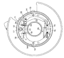
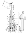
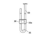
図1〜図3は本発明の一実施例を示すものであり、図1はドラムブレーキの正面図、図2はパーキング駆動手段の縦断面図、図3は図2の3矢視図である。 1 to 3 show an embodiment of the present invention, FIG. 1 is a front view of a drum brake, FIG. 2 is a longitudinal sectional view of a parking drive means, and FIG. 3 is a view taken in the direction of arrow 3 in FIG. .
先ず図1において、パーキングブレーキ専用のブレーキ機構であるドラムブレーキ11が備えるバックプレート12は、図示しないブレーキドラムの開放端を覆うようにして車体側に固定的に取付けられる。前記ブレーキドラムに摺接し得るライニング14,14を有してブレーキドラム内に配置される一対のブレーキシュー13,13の一端は伸縮調節可能なストラット15の両端に揺動可能に支承され、両ブレーキシュー13…の一端間には前記ストラット15の両端側に両ブレーキシュー13…を付勢するばね16が縮設される。また両ブレーキシュー13…の他端は、前記バックプレート12に設けられたアンカ17に離間可能に支承されるとともに戻しばね18によって前記アンカ17で支承される側に付勢される。また両ブレーキシュー13…の他端側対向面には切欠き19…がそれぞれ設けられており、それらの切欠き19…にストラット21の両端が係合され、ストラット21の一端および一方のブレーキシュー13間にはばね22が縮設される。
First, in FIG. 1, a
一方の前記ブレーキシュー13と一部が重なるようにしてパーキング作動レバー23が前記ブレーキシュー13およびバックプレート12間に配置されており、該作動レバー23の一端にパーキング駆動手段25が連結される。またパーキング作動レバー23の他端部は、前記ストラット21の一端に係合されるとともに一方の前記ブレーキシュー13の他端部に枢軸24を介して揺動可能に連結される。
A
而して前記パーキング駆動手段25によって前記パーキング作動レバー23を枢軸24のまわりに図1の時計方向に回動せしめると、ストラット21を介して他方のブレーキシュー13がブレーキドラムの内周に圧接され、その反作用によって一方のブレーキシュー13もブレーキドラムの内周に圧接され、それによりドラムブレーキ11によるパーキングブレーキ状態を得ることができる。
Thus, when the
図2を併せて参照して、前記パーキング駆動手段25は、前記両ブレーキシュー13…の一端側でバックプレート12に固定されるケーシング26を備える。該ケーシング26には一端が端壁26aで閉じられる第1摺動孔27が設けられる。
Referring also to FIG. 2, the parking driving means 25 includes a
ケーシング26の第1摺動孔27には、背面側へのパーキング用制御液圧の作用に応じた前進作動によってパーキングブレーキ状態を得ることを可能としたパーキングピストン30が摺動可能に嵌合され、該パーキングピストン30の外周には環状のシール部材31が装着される。このパーキングピストン30の背面および前記端壁26a間でケーシング26内に、パーキング用制御液圧を作用させることを可能としたパーキング用制御液圧室32が形成される。
The first sliding
前記パーキングピストン30には、該パーキングピストン30と一体的に作動する連動部材であるロッド33が、パーキングピストン30の中央部を貫通するようにして圧入されており、該ロッド33の一端側は環状のシール部材34を介して前記端壁26aを液密にかつ摺動自在に貫通する。しかも前記ロッド33は、その一端側に小径連結軸部33aを備えており、その小径連結軸部33aが、ドラムブレーキ11におけるパーキング作動レバー23の一端部に連結される。したがって前記パーキングピストン30およびロッド33の前進作動に応じた牽引力が前記パーキング作動レバー23に入力され、それによりパーキング作動レバー23がドラムブレーキ11をパーキング作動せしめる側に回動することになる。
A
図3を併せて参照して、前記パーキング作動レバー23の一端部はスリット35を形成するようにして略U字状に折り曲げられており、そのスリット35に挿通される前記小径連結軸部33aの端部に、パーキング作動レバー23の一端部に当接、係合する係合部材36が固着される。しかも係合部材36を当接、係合せしめるべくパーキング作動レバー23に設けられる当接面37は円弧状のものであり、前記パーキングピストン30の前進作動に伴ってパーキング作動レバー23に作用する牽引力が最大になるときの前記係合部材36の接触点での前記当接面37の接線が、ロッド33すなわち小径連結軸部33aからパーキング作動レバー23への牽引力作用方向と直角となるだけでなく、ロッド33の全ストローク領域で係合部材36の接触点での前記接線が前記牽引力作用方向と直角となるように形成される。
Referring also to FIG. 3, one end portion of the
しかも係合部材36の少なくとも前記当接面37に接触する部分の外面形状は当接面37に向かって凸である曲面状に形成されている。
In addition, the outer surface shape of at least the portion of the
またケーシング26内には、前記パーキングピストン30を前進位置で機械的にロックすべく該パーキングピストン30の前進作動に応じて自動的にロック作動するとともに、パーキング解除用制御液圧の作用に応じてロック解除作動するロック機構43が設けられる。
Further, in the
このロック機構43は、パーキングピストン30と一体的に作動するロッド33の他端側外周に設けられて軸方向に連なるラチェット歯44と、該ラチェット歯44に係合する方向に回動付勢されるとともにパーキング解除用制御液圧の作用に応じてラチェット歯44との係合を解除する側に回動するようにしてケーシング26に回動自在に支承される係合爪45とを備える。
The
ケーシング26には、第1摺動孔27の中間部に対応する部分で一端を閉じた有底の第2摺動孔46が第1摺動孔27と平行に設けられており、第2摺動孔46の他端開口部は蓋部材47で液密に閉じられる。また第2摺動孔46の一端閉塞部寄りで第2摺動孔46および第1摺動孔27間を結ぶ支持孔48と、該支持孔48と反対側で第2摺動孔46に内端を開口するとともに外端をケーシング26の外面に開口する規制孔49とがケーシング26に設けられる。
The
ラチェット歯44に一端を係合し得る係合爪45は、その他端をケーシング26から外方に突出させるようにして前記支持孔48および規制孔49に挿入されており、第1および第2摺動孔27,46の軸線を含む平面と直交する軸線を有して前記支持孔48を横切る支軸50を介して係合爪45がケーシング26に回動自在に支承され、係合爪45の回動範囲は、該係合爪45の他端側が規制孔49の内面に当接する範囲に規制される。
An engaging claw 45 capable of engaging one end with the
また第2摺動孔46の一端閉塞部および係合爪45間にはばね51が設けられており、係合爪45は、前記ばね51のばね力によってラチェット歯44に係合する方向に弾発付勢される。
Further, a
また係合爪45に関して前記ばね51とは反対側で第2摺動孔46には、前記蓋部材47との間にパーキング解除用制御液圧室53を形成する制御ピストン52が摺動可能に嵌合される。この制御ピストン52は前記ばね51とは反対側から係合爪45に当接しており、前記ばね51のばね力に打ち勝って前記係合爪45をラチェット歯44との係合を解除する側に押圧することができる。
In addition, the
パーキング用制御液圧室32に作用せしめるパーキング用制御液圧ならびにパーキング解除用制御液圧室53に作用せしめるパーキング解除用制御液圧は、液圧発生源55の発生液圧を液圧制御手段56で制御することにより得られるものであり、この液圧制御手段56は、パーキング用制御液圧室32を液圧発生源55およびリザーバ57に択一的に連通させる第1制御弁58と、パーキング解除用制御液圧室53を液圧発生源55およびリザーバ57に択一的に連通させる第2制御弁59とから成る。
The parking control fluid pressure acting on the parking control
パーキングブレーキ状態を得るときには、パーキング解除用制御液圧室53の液圧を解放した状態でパーキング用制御液圧室32にパーキング用制御液圧を作用させる。そうするとパーキングピストン30およびロッド33は、ラチェット歯44で係合爪45をはね上げるようにして前進し、パーキング作動レバー23が回動駆動されることによってドラムブレーキ11によるパーキングブレーキ状態が得られることになり、パーキングピストン3お0よびロッド33の静止状態で係合爪45がラチェット歯44に係合することにより、パーキングピストン30の前進作動状態が機械的にロックされ、このロック状態はパーキング用制御液圧室32の液圧を解放しても維持される。
When the parking brake state is obtained, the parking control hydraulic pressure is applied to the parking control
ドラムブレーキ11のパーキングブレーキ状態を解除するにあたっては、先ずパーキング用制御液圧室53に液圧発生源55からの液圧を作用せしめる。そうすると、パーキングピストン30およびロッド33が前進し、ラチェット歯44から係合爪45にかかっている力が減少するので、次にパーキング解除用制御液圧室53に液圧発生源55からの液圧を作用せしめると、係合爪45がラチェット歯44との係合を解除する位置まで退避する位置まで回動する。そこでパーキング用制御液圧室53の液圧を解放するとドラムブレーキ11が備える戻しばね18のばね力により、パーキング作動レバー23が、パーキングピストン30およびロッド33を後退させつつ元の位置まで戻る。そこでパーキング解除用制御液圧室53の液圧を解放することで、パーキングブレーキ状態を得る前の状態に戻ることになる。
In releasing the parking brake state of the
ところで、前記パーキング駆動手段25はアジャスト機構60を備えるものであり、このアジャスト機構60は、第1摺動孔27の他端部にねじ込み等で固定されるリング状のばね受け部材61と、該ばね受け部材61に内方から対向するようにして摺動可能に嵌合されるとともに前記ロッド33の他端側を軸方向移動可能に貫通せしめる貫通孔63が中央部に設けられる調整用ピストン62と、該調整用ピストン62から外方に突出する部分でロッド33の外周のラチェット歯44に係合し得るようにして調整用ピストン62に装着される調整用係合爪64と、該調整用係合爪64をラチェット歯44に係合させるようにばね付勢するようにしてばね受け部材61および調整用係合爪64間に設けられる調整用ばね65とを備える。
By the way, the parking drive means 25 is provided with an
このようなアジャスト機構60では、非パーキングブレーキ状態では、調整用ピストン62がばね受け部材61から距離Lだけ離隔した位置にあり、この状態でパーキングブレーキ状態を得るためにパーキングピストン30を前進作動せしめると、該パーキングピストン30と一体に前進作動するロッド33のラチェット歯44に調整用係合爪64が係合していることによって、調整用ピストン62がばね受け部材61に近接する側に前記距離L未満の距離だけ前進する。しかるにドラムブレーキ11におけるブレーキシュー13…のライニング14…が摩耗することによってパーキングピストン30の前進移動量が大きくなると、調整用係合爪64を付勢している調整用ばね65のばね力に打ち勝ってラチェット歯44すなわちロッド33は調整用係合爪64を押しのけるように前進移動することになり、前記調整用係合爪64は前記ラチェット歯44のうちパーキングピストン30により近い側に係合することになる。
In such an
したがって前記ライニング14…の摩耗量にかかわらず、パーキングブレーキ作動時のパーキングピストン30の前進ストロークが前記アジャスト機構60によってほぼ一定に維持されることになる。
Therefore, regardless of the amount of wear of the
次にこの実施例の作用について説明すると、ドラムブレーキ11をパーキングブレーキ作動せしめる際には、パーキング駆動手段25が有するパーキングピストン30の背面側が臨むパーキング用制御液圧室32にパーキング用制御液圧を作用させればよく、パーキングピストン30を前進作動せしめることにより、ドラムブレーキ11をブレーキ作動せしめてパーキングブレーキ状態を得ることが可能となり、またパーキングピストン30の前進作動によるパーキング作動状態がロック機構43で機械的にロックされるので、パーキングブレーキ状態を自動的に得ることができ、パーキングブレーキ状態では電力消費を伴わない簡単な構造でパーキングブレーキ状態を自動的に得ることができる。
Next, the operation of this embodiment will be described. When the
またロック機構43は、パーキングピストン30と一体的に作動するロッド33に設けられて軸方向に連なるラチェット歯44と、該ラチェット歯44に係合する方向に回動付勢されるとともにパーキング解除用制御液圧の作用に応じてラチェット歯44との係合を解除する側に回動するようにしてケーシング26に回動自在に支承される係合爪45とを備えるものであり、ロック機構43の構成を簡略化することができる
さらにロッド33がその一端側に備える小径連結軸部33aの端部に固定される係合部材36が、パーキング作動レバー23の一端部に当接、係合されるのであるが、係合部材36を当接、係合せしめるべく、パーキング作動レバー23に設けられる円弧状の当接面37は、前記パーキングピストン30の前進作動に伴ってパーキング作動レバー23に作用する牽引力が最大になるときの前記係合部材36の接触点での前記当接面37の接線が、ロッド33すなわち小径連結軸部33aからパーキング作動レバー23への牽引力作用方向と直角となるだけでなく、ロッド33の全ストローク領域で係合部材36の接触点での前記接線が前記牽引力作用方向と直角となるように形成される。
The
したがってパーキング作動レバー23に作用する牽引力が最大になるときに、ロッド33およびパーキング作動レバー23間にこじりが生じるのを抑制し、耐久性の向上を図ることができるだけでなく、ロッド33の全ストローク領域でロッド33およびパーキング作動レバー23間にこじりが生じるのを抑制し、耐久性のより一層の向上を図ることができる。
Accordingly, when the traction force acting on the
また係合部材36の少なくとも前記当接面37に接触する部分の外面形状が当接面37に向かって凸である曲面状に形成されているので、ロッド33およびパーキング作動レバー23間にこじりが生じるのをより効果的に抑制することができ、パーキング作動レバー23および係合部材36の接触面積を比較的大きくして応力緩和を図ることができる。
In addition, since the outer surface shape of at least the portion of the engaging
しかもパーキング作動レバー23に設けられるスリット35に小径連結軸部33aを挿通せしめることでロッド33をパーキング作動レバー23に係合、連結することができるので組付け性もよい。
Moreover, since the
以上、本発明の実施例を説明したが、本発明は上記実施例に限定されるものではなく、特許請求の範囲に記載された本発明を逸脱することなく種々の設計変更を行うことが可能である。 Although the embodiments of the present invention have been described above, the present invention is not limited to the above-described embodiments, and various design changes can be made without departing from the present invention described in the claims. It is.
26・・・ケーシング
30・・・パーキングピストン
33・・・連動部材としてのロッド
43・・・ロック機構
44・・・ラチェット歯
45・・・係合爪
55・・・液圧発生源
56・・・液圧制御手段
26 ... casing 30 ...
Claims (1)
Priority Applications (1)
| Application Number | Priority Date | Filing Date | Title |
|---|---|---|---|
| JP2004107499A JP2005291374A (en) | 2004-03-31 | 2004-03-31 | Parking brake device |
Applications Claiming Priority (1)
| Application Number | Priority Date | Filing Date | Title |
|---|---|---|---|
| JP2004107499A JP2005291374A (en) | 2004-03-31 | 2004-03-31 | Parking brake device |
Publications (1)
| Publication Number | Publication Date |
|---|---|
| JP2005291374A true JP2005291374A (en) | 2005-10-20 |
Family
ID=35324530
Family Applications (1)
| Application Number | Title | Priority Date | Filing Date |
|---|---|---|---|
| JP2004107499A Pending JP2005291374A (en) | 2004-03-31 | 2004-03-31 | Parking brake device |
Country Status (1)
| Country | Link |
|---|---|
| JP (1) | JP2005291374A (en) |
Cited By (2)
| Publication number | Priority date | Publication date | Assignee | Title |
|---|---|---|---|---|
| JP2006161923A (en) * | 2004-12-06 | 2006-06-22 | Advics:Kk | Parking brake equipment |
| JP2015161344A (en) * | 2014-02-26 | 2015-09-07 | ジヤトコ株式会社 | Vehicular brake system |
-
2004
- 2004-03-31 JP JP2004107499A patent/JP2005291374A/en active Pending
Cited By (2)
| Publication number | Priority date | Publication date | Assignee | Title |
|---|---|---|---|---|
| JP2006161923A (en) * | 2004-12-06 | 2006-06-22 | Advics:Kk | Parking brake equipment |
| JP2015161344A (en) * | 2014-02-26 | 2015-09-07 | ジヤトコ株式会社 | Vehicular brake system |
Similar Documents
| Publication | Publication Date | Title |
|---|---|---|
| CN109476283B (en) | Parking brake and how to operate | |
| JP4401568B2 (en) | Rocker brake assembly with hydraulic lock | |
| JP4084775B2 (en) | Parking brake device | |
| CN107889517B (en) | Wedge cam type brake | |
| EP1729027B1 (en) | Parking brake device | |
| JP2001206213A (en) | Brake cylinder device | |
| JP2005291374A (en) | Parking brake device | |
| US6523652B2 (en) | Drum brake device | |
| JP4053017B2 (en) | Parking brake device for drum brake | |
| JP4084774B2 (en) | Parking brake device | |
| WO2017022847A1 (en) | Wedge cam brake | |
| US6286643B1 (en) | Parking brake mechanism in drum brake | |
| JP2001343037A (en) | Dual mode drum brake device | |
| JP2005291375A (en) | Parking brake device | |
| JP2005291373A (en) | Parking brake device | |
| JP2008169952A (en) | Brake device | |
| JP2005291366A (en) | Parking brake device | |
| JP2005291372A (en) | Parking brake device | |
| RU2007639C1 (en) | Automatic clearance regulator in brake mechanisms of vehicles | |
| JP2006125619A (en) | Brake device for vehicle | |
| JP2007132394A (en) | Brake device for vehicle | |
| JP2001027266A (en) | Duo-to-leading drum brake system | |
| JP4393896B2 (en) | Drum brake device | |
| JPH07158668A (en) | Lifting prevention structure of friction pad in vehicle disc brake | |
| KR101861017B1 (en) | Wear Compensation Device of Clutch Actuator |