JP2005291305A - Sealed rolling bearings and seals - Google Patents
Sealed rolling bearings and seals Download PDFInfo
- Publication number
- JP2005291305A JP2005291305A JP2004105217A JP2004105217A JP2005291305A JP 2005291305 A JP2005291305 A JP 2005291305A JP 2004105217 A JP2004105217 A JP 2004105217A JP 2004105217 A JP2004105217 A JP 2004105217A JP 2005291305 A JP2005291305 A JP 2005291305A
- Authority
- JP
- Japan
- Prior art keywords
- lip
- seal
- sealing
- reinforcing
- radial
- Prior art date
- Legal status (The legal status is an assumption and is not a legal conclusion. Google has not performed a legal analysis and makes no representation as to the accuracy of the status listed.)
- Withdrawn
Links
Images
Classifications
-
- F—MECHANICAL ENGINEERING; LIGHTING; HEATING; WEAPONS; BLASTING
- F16—ENGINEERING ELEMENTS AND UNITS; GENERAL MEASURES FOR PRODUCING AND MAINTAINING EFFECTIVE FUNCTIONING OF MACHINES OR INSTALLATIONS; THERMAL INSULATION IN GENERAL
- F16C—SHAFTS; FLEXIBLE SHAFTS; ELEMENTS OR CRANKSHAFT MECHANISMS; ROTARY BODIES OTHER THAN GEARING ELEMENTS; BEARINGS
- F16C2326/00—Articles relating to transporting
- F16C2326/01—Parts of vehicles in general
- F16C2326/02—Wheel hubs or castors
Landscapes
- Sealing Of Bearings (AREA)
- Rolling Contact Bearings (AREA)
Abstract
Description
本願発明は、密封ころがり軸受、特に、密封耐久性を向上した自動車車輪用に好適な密封ころがり軸受に関する。 The present invention relates to a sealed rolling bearing, and more particularly to a sealed rolling bearing suitable for automobile wheels having improved sealing durability.
車輪用密封ころがり軸受の密封シールは、金属製の芯金にゴム材を焼付け、該ゴム材にアキシャルリップと1つないし2つのラジアルリップとを設け、これらのシールリップに対向させて金属製のスリンガを相手部材として設け、前記芯金を外輪内周面の、そして、前記スリンガを内輪外周面の所定位置に夫々嵌合し、これらのシールリップをスリンガに摺接させて、密封シール装置を構成しているものが広く使用されている(例えば、特許文献1参照)。
しかしながら、芯金に設けられたアキシャルリップ及びラジアルリップなどのシールリップにはゴム材料を使用しており、前記両リップが金属製のスリンガと摺接して、密封シール装置を形成しているので、泥水や砂などの異物がリップ面に噛みこむことにより、シールリップやスリンガの摺接部が磨耗したりする。また、長期の使用や高温に晒されることによる変形をおこしたりすることもあって、シールリップのスリンガなど相手部材へのリップ圧力が低下してくる。これらが、密封シール装置の密封耐久性に影響を及ぼす要因となって、密封耐久性の劣化につながってくる。 However, a rubber material is used for seal lips such as an axial lip and a radial lip provided on the metal core, and both the lips are in sliding contact with a metal slinger to form a hermetic seal device. When foreign matter such as muddy water or sand bites into the lip surface, the sliding contact portion of the seal lip or slinger wears out. In addition, the lip pressure on the mating member such as the slinger of the seal lip is lowered due to deformation due to long-term use or exposure to high temperatures. These become factors that affect the sealing durability of the hermetic seal device and lead to deterioration of the sealing durability.
本願発明はこのような点に鑑みなされたもので、摺接面への異物が噛込んだり、長期間の使用や高温に晒されて変形しても、密封耐久性の高い密封シールを備えた密封ころがり軸受を提供することを目的とし、また、密封耐久性の高い密封シールを提供することを目的としている。 The present invention has been made in view of such points, and has a sealing seal with high sealing durability even if foreign matter is caught on the sliding contact surface or deformed by being exposed to high temperatures or being exposed to high temperatures for a long period of time. It is an object to provide a sealed rolling bearing and to provide a hermetic seal having high sealing durability.
上記の目的を達成するため、本願発明の密封ころがり軸受によって、すなわち、
外輪と、
内輪と、
前記外輪と前記内輪間に介装される転動体と
前記外輪と前記内輪との間に形成される軸受空間を密封するための密封シールと、
からなる密封ころがり軸受において、
前記密封シールは、外輪または内輪の一方に固定され、シールリップを一体に有する弾性シール部材と、
外輪または内輪の他方に設けられ前記シールリップと当接する相手部材と、
前記シールリップの背面を押圧して相手部材に対するリップ圧力を増強する補強リップと、
を備えたことを特徴とする密封ころがり軸受によって課題の解決を図る。
In order to achieve the above object, the sealed rolling bearing of the present invention, that is,
Outer ring,
Inner ring,
A rolling element interposed between the outer ring and the inner ring; and a sealing seal for sealing a bearing space formed between the outer ring and the inner ring;
In a sealed rolling bearing consisting of
The hermetic seal is fixed to one of the outer ring or the inner ring, and an elastic seal member integrally having a seal lip;
A mating member provided on the other of the outer ring or the inner ring and in contact with the seal lip;
A reinforcing lip that presses the back surface of the seal lip to increase the lip pressure against the mating member;
The problem is solved by a sealed rolling bearing characterized by comprising
また、本願発明の密封ころがり軸受によって、すなわち、
前記シールリップは、軸方向外方に向かって延在するアキシャルリップであり、前記弾性シール部材は前記アキシャルリップの背面を押圧する補強リップを備えたことを特徴とする密封ころがり軸受によって課題の解決を図る。
Moreover, by the sealed rolling bearing of the present invention, that is,
The seal lip is an axial lip extending outward in the axial direction, and the elastic seal member is provided with a reinforcing lip that presses the back surface of the axial lip. Plan.
また、本願発明の密封ころがり軸受によって、すなわち、
前記シールリップは、半径方向他方に向かって延在するラジアルリップであり、前記弾性シール部材は前記ラジアルシールの背面を押圧する補強リップを備えたことを特徴とする密封ころがり軸受によって課題の解決を図る。。
Moreover, by the sealed rolling bearing of the present invention, that is,
The seal lip is a radial lip extending in the other radial direction, and the elastic seal member is provided with a reinforcing lip that presses the back surface of the radial seal. Plan. .
また、本願発明の密封ころがり軸受によって、すなわち、
相手部材がスリンガまたはハブであることを特徴とする密封ころがり軸受によって課題の解決を図る。
Moreover, by the sealed rolling bearing of the present invention, that is,
The problem is solved by a sealed rolling bearing in which the mating member is a slinger or a hub.
さらに、また、本願発明の密封シールによって、すなわち、
弾性シール部材と、前記弾性シール部材のシールリップと当接する相手部材と、前記シールリップの背面を押圧して前記相手部材に対するリップ圧力を増強する補強リップとを備え、外輪と内輪との軸受空間を密封することを特徴とする密封シールによって課題の解決を図る。
Furthermore, also by the hermetic seal of the present invention, ie
A bearing space between the outer ring and the inner ring, comprising: an elastic seal member; a mating member that contacts the seal lip of the elastic seal member; and a reinforcing lip that presses the back surface of the seal lip to increase the lip pressure against the mating member. The problem is solved by a hermetic seal characterized by sealing the seal.
本願発明によれば、密封耐久性の高い、密封ころがり軸受けが得られる。また、密封耐久性の高い密封シールが得られる。 According to the present invention, a sealed rolling bearing with high sealing durability can be obtained. Moreover, a hermetic seal with high sealing durability can be obtained.
以下、本願発明の実施形態に関わる密封ころがり軸受及び密封シールを図面を参照しつつ説明する。 Hereinafter, a sealed rolling bearing and a hermetic seal according to an embodiment of the present invention will be described with reference to the drawings.
(実施形態1)
図1、図2によって本願発明の実施形態1の密封ころがり軸受を説明する。
(Embodiment 1)
The sealed rolling bearing according to the first embodiment of the present invention will be described with reference to FIGS.
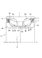
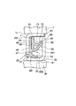
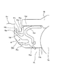
図1は本実施形態の密封ころがり軸受のX-X中心線より上側半分を示している断面図である。図2は図1の破線部Aの拡大図である。 FIG. 1 is a cross-sectional view showing the upper half of the sealed rolling bearing of the present embodiment from the XX center line. FIG. 2 is an enlarged view of a broken line portion A in FIG.
図1において、密封ころがり軸受Huは複列の内周軌道1a1、1a2を有する外輪1と、内周軌道1a1、1a2に対向する外周軌道2a1、2b1をそれぞれ有する一対の内輪要素2a,2bと、密封ころがり軸受Huの両端部で外輪1と内輪要素2a,2bとの間の空間を密封する密封シール4a,4bと外輪1、内輪要素2a,2b間に介装されている2列のボール3a,3bと、2列のボール3a,3bを保持する保持器8a,8bとから構成されている。
In FIG. 1, a sealed rolling bearing Hu includes a pair of inner rings each having an
外輪1は両端部内周に前記内周軌道1a1、1a2にそれぞれ連なる円筒面1c,1cを備えている。内輪要素2a,2bは、外周軌道2a1、2b1に連設されている小径の終端部2c1,2c2で互いに突き当てられて、全体として一対の内輪要素2a,2bからなる複列の内輪2を形成している。
The
保持器8a,8bはそれぞれ冠型保持器といわれるタイプで樹脂製で図1中、ころがり軸受の中央部からボール3a,3bを抱くように組み込まれ、ボール3a,3bを保持している。
Each of the
密封シール4a,4bを図2と併せて説明する。
The
密封シール4a,4bは同一構造(軸受に組みつけた状態では左右対称になっている。)なので、右側の4bについてのみ、図2を参照しながら説明する。
Since the
密封シール4bは芯金41と該芯金41に接着されているゴムなど弾性シール部材45と、該弾性シール部材45と当接して相手部材となるスリンガ60とによって構成されている。
The
密封シール4bの芯金41は円筒面42と該円筒面42に直角に半径方向内方に折り曲げられたつば部43を一体に有し、前記つば部43の内側面44に、前記弾性シール部材45が被覆され、該弾性シール部材45から複数のシールリップ410が突出している。
The
複数のシールリップ410には、前記つば部43の内側面44の弾性シール部材45を上部域46と下部域47とに区分けするように、弾性シール部材45の略中央部から軸方向外方(図面右方)に延在している腕部481が設けられ、該腕部481の先端に設けられていて相手部材であるスリンガ(後述する)と摺接するアキシャルリップ48と、前記腕部481の下部域47に連なって形成されている下側腕部491と該下側腕部491に連なって設けられ、半径方向内方(図2下方)に延在して相手部材であるスリンガ(後述する)と摺接する第1ラジアルリップ50と、該第1ラジアルリップに隣接して軸受の内部側(図2左方)に形成されている第2ラジアルリップ51とからなっている。
The plurality of
芯金41はその円筒面42の外周が外輪1の端部内周の円筒面1cに嵌合固定されている。嵌合はつば部43の外側面431をボール8b(図2左方)に向けて取付けられている。
The outer periphery of the cylindrical surface 42 of the
さらに、弾性シール部材45の上域部46には前記弾性シール部材45とは別体の補強部材70が取付けられている。該別体の補強部材70は半径方向略中央部から軸方向外方に補強リップ71が延在し、補強リップ71の先端部72が前記腕部481の先端にあるアキシャルリップ48の背面を押圧してアキシャルリップ48を後述するスリンガ内側面63へ押し付けるリップ圧力を増強している。
Further, a reinforcing
スリンガ60は円筒面61と該円筒面61に直角に外方に折り曲げられたつば部62を有していて、円筒面61は内輪要素2bの外周面2dに外嵌固定されている。つば部62の内側面63にはアキシャルリップ48が、そして円筒面61の外周面64には第1ラジアルリップ50および第2ラジアルリップ51とが摺接している。
The
このように芯金41に接着されている密封シール部材45とスリンガ60は、密封シール部材45に設けられているにアキシャルリップ48がスリンガ60の内側面63に所定のリップ圧力で当接するように、芯金41とスリンガ60は外輪の円筒面1cおよび内輪端部外周面2dの所定の位置に固定されており、また、第1ラジアルリップ50と第2ラジアルリップ51もスリンガ60の円筒面61の外周面64と所定のリップ圧力で当接するようになっている。芯金41とスリンガ60を所定の位置に取付けることによって、スリンガ60とアキシャルリップ48、第1ラジアルリップ50、第2ラジアルリップ51とに補強部材70の補強リップ71を加えることにより密封シール4bを構成し、高耐久の密封効果を奏することができる。
Thus, the sealing
ここで、アキシャルリップ48、第1ラジアルリップ50および第2ラジアルリップ51を形成している弾性シール部材45ならびにリップ圧力を増強する補強リップ71に用いる弾性部材は、ニトリルゴム、水素添加ニトリルゴム、フッ素ゴムなどから選択し、摺接面から発生するトルクを低減するのに含油性ゴムなどを使用できるし、また、リップ圧力を増強するには、図2に示すように補強リップ71の断面をV形状に折り曲げたり、または補強リップの肉厚を増したりして高反発性を有する形状にして、全体として、摺接トルクを小さく抑えながら、かつ、長期間の使用にも安定した高耐久密封性を得ることができる。
Here, the
以下に説明する変形例1、2及び実施形態2においても同様に実施するものである。
The same applies to
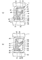
さらに、図3(a)、(b)、において実施形態1の変形例1、2を説明する。 Further, modified examples 1 and 2 of the first embodiment will be described with reference to FIGS.
変形例1を示す図3(a)において、該変形例1は芯金41に接着されているゴムなど弾性部材の弾性シール部材45から軸方向外方(図3(a)右方)に向かって延びる腕部481の先端に設けられているアキシャルリップ48と、ラジアル内方向に延びる第1のラジアルリップ50と第2のラジアルリップ51とを設けている。アキシャルリップ48の腕部481によって区分されている上部域46に、弾性シール部材45とは別体の補強部材70が取付けられており、該補強部材70はアキシャルリップ48の背面から接触押圧してリップ圧力を増強させる補助リップ71を設け、その先端72でアキシャルリップ48をスリンガ60のつば部62の内側面63に対して押圧するが、この構成までは図1、図2に示す実施形態1と同じである。
In FIG. 3A showing the first modification, the first modification is directed outward (in the right direction in FIG. 3A) from the
図3(a)は、さらにアキシャルリップ48の腕部481によって区分けされている下部域47に弾性シール部材45とは別体の補強部材75を取付けている。該補強部材75は半径方向下方に向かう補強リップ76を有し、第1ラジアルリップ50を背面から押圧してスリンガ60の円筒面61の外周面64面へのリップ圧力を高めている。
In FIG. 3A, a reinforcing
この変形例1によるとアキシャルリップ48とスリンガ60とによる密封シール部を水分など異物が通過した場合でも、この第1のラジアルリップ50とスリンガ60との密封シール効果によって、阻止することができる。アキシャルリップによる密封シール部と第1ラジアルリップによる密封シール部との二段構えにより、密封シール4bとしての密封耐久性は格段に向上する。
According to the first modification, even when foreign matter such as moisture passes through the sealing seal portion formed by the
変形例2を示す図3(b)において、芯金41に焼き付けられている弾性シール部材45の中央部より少し上側(図3(b)上方)に上部域46と下部域47とに区分するように腕部78を設け、該腕部78は軸方向外方(図3(b)右方)に延びてその先端で補強リップ79を形成している。
In FIG. 3B showing the second modification, the
前記腕部78の下部域47に、補強部材74が取付けられ、該補強部材74には軸方向外方(図3(b)右方)に伸びる腕部75と、その先端にアキシャルリップ77が設けられている。
A reinforcing
補強部材74は弾性シール部材45とは別体の部材である。補強部材74のアキシャルリップ77はスリンガ60のつば62の内側面63に摺接している。補強部材74を腕部下部域47に取付けて、補強部材74のアキシャルリップ77の背面から腕部78の先端の補強リップ79を押当てスリンガ60のつば62の内側面63へのリップ圧力を増強している。
The reinforcing
さらに、補強部材74にはアキシャルリップ77の腕部75の下方に第1ラジアルリップ50の背面から、該第1ラジアルリップ50を押圧する補強リップ76が一体に設けられている。
Further, a reinforcing
変形例2によると、ひとつの補強部材74にアキシャルリップ77と第1ラジアルリップ50に対する補強リップ76とを設けてあり、摺接トルクの小さい材料と高反発性の両特性を有する材料を選択することにより密封シールを形成するものである。
According to the modified example 2, the
なお、第1ラジアルリップ50及び第2ラジアルリップ51は、弾性シール部材45の半径方向下方に一体形成された変形例1と同様に設けてある。
The first
(実施形態2)
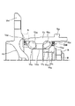
図4に本願発明の実施形態2の中心線より上側半分の断面図を示している。
同図において、ハブU1は外端側に車輪(図示略)を取付けるためのフランジU1fと、軸方向中央部の外周面U1mのうちフランジ側外周面には、前記外周面に直接第1の軸受軌道U1aが形成されている。車両中心側の外周面は、フランジ側外周面より段部U1cを介して、小径外周面U1nが設けられ、該小径外周面の車両中心側(図1中、右方)終端部は、ボルト・ナットB・Nにより締結可能になっている。
(Embodiment 2)
FIG. 4 shows a cross-sectional view of the upper half of the center line of
In the figure, the hub U 1 is a flange U 1f for mounting a wheel (not shown) on the outer end, the flange outer peripheral surface of the outer circumferential surface U 1 m axial central portion, first directly on the outer peripheral surface One bearing raceway U 1a is formed. The outer peripheral surface on the vehicle center side is provided with a small-diameter outer peripheral surface U 1n via a stepped portion U 1c from the flange-side outer peripheral surface, and the vehicle central side (right side in FIG. 1) end portion of the small-diameter outer peripheral surface is It can be fastened with bolts and nuts B and N.
内輪要素U3はハブU1の小径外周部U1nに外嵌された後、前記段部U1cとナットNによって固定されている。内輪要素の外周には第2の軸受軌道U1bが形成されている。 The inner ring element U 3 is externally fitted to the small-diameter outer peripheral portion U 1 n of the hub U 1 , and then fixed by the stepped portion U 1 c and the nut N. A second bearing race U1b is formed on the outer periphery of the inner ring element.
外輪U2はハブU1の第1の軸受軌道U1a及び第2の軸受軌道U1bに対応する複列の軸受軌道U2a,U2bを有している。外輪U2の外周部には車体に取付けるフランジU2fが一体に形成されている。 Outer ring U 2 has a first bearing raceway U 1a and the second bearing raceway U of 1b double row corresponding to the bearing raceway U 2a, U 2b of the hub U1. A flange U 2f attached to the vehicle body is integrally formed on the outer peripheral portion of the outer ring U 2 .
外輪の両側部にはハブU1と外輪U2との間を密封する密封シールU4A,U4Bが取付けられている。 Sealing seals U 4A and U 4B for sealing between the hub U 1 and the outer ring U 2 are attached to both sides of the outer ring.
フランジ側の密封シールU4Aを図4の破線部Bを拡大して示している図5によって詳しく説明する。 The flange side hermetic seal U4A will be described in detail with reference to FIG. 5 showing an enlarged broken line portion B in FIG.
密封シールU4aは外輪U2の内周に内嵌固定された芯金U41と、該芯金U41に焼き付けされ芯金U41の軸方向外方を覆うゴムなどの弾性部材による被覆層U45とからなる。該被複層U45の半径方向中央部には、軸方向外方(図面左方)に腕部U42が設けられ、該腕部U42の先端には第1のアキシャルリップU47が形成され、さらにその下方には第2のアキシャルリップU43を一体に備え、さらに、半径方向下方(図面下方)に向けてラジアルリップU44を一体に有している。 Hermetic seal U 4a is a core metal U 41, which is fitted and fixed to the inner periphery of the outer ring U 2, the coating layer of the elastic material such as rubber which covers an axially outward of the core U 41 is burned into core metal U 41 U 45 . The radial direction central portion of the該被multilayer U 45, arms U 42 is provided axially outward (drawing left), the first axial lip U 47 is formed at the tip of the arm portion U42 Further, a second axial lip U 43 is integrally provided below, and a radial lip U 44 is integrally provided downward in the radial direction (downward in the drawing).
第1のアキシャルリップU47はフランジU1fに摺接している。さらに、第1のアキシャルリップU47の上部域U46には、被覆層U45とは別部材からなる補強部材U70が取付けられ、該補強部材U70からは軸方向外方(図面、左方)に補強リップU71が突き出ていて、その先端が前記第1のアキシャルリップU47を、その背面からフランジU1fへ押圧し、前記フランジU1fとの間のリップ圧力を増強している。第2のアキシャルリップU43は、ハブU1のフランジ部U1fと円筒部U1hの境界部にあるアール部Rと摺接する。ラジアルリップU44はハブの円筒部U1hに摺接する。 The first axial lip U 47 is in sliding contact with the flange U 1f. Furthermore, the upper region U 46 of the first axial lip U 47, the coating layer U 45 attached reinforcing member U 70 made of separate members, axially outwardly from the reinforcing member U 70 (drawing, left It has protruding reinforcing lip U 71 in how), and the distal end of the first axial lip U 47, is pressed from its back surface to the flange U 1f, to enhance the lip pressure between the flange U 1f . The second axial lip U 43 is rounded portion R in sliding contact at the boundary portion of the flange portion U 1f and the cylindrical portion U 1h of the hub U 1. Radial lip U 44 is in sliding contact with the cylindrical portion U 1h of the hub.
かくして、密封シールU4Aとハブのフランジ及び軸の円筒部と摺接させることにより、密封シール装置U40を備えた密封ころがり軸受を構成できる。 Thus, by the cylindrical portion and the sliding contact of the flange and the axis of the hermetically sealed U 4A and hub it can be configured to seal rolling bearings with a hermetic seal device U 40.
図4に示すように、車両中心側には、内輪要素U3の端部外周部U3dと、該外周部に対向する外輪U2の端部内周部U2dとの間に密封シールU4Bが取付けられる。該密封シールU4Bは本願発明の実施形態1もしくはその変形例1、2などを使用しているので説明を省略する。なお、用途によっては従来品でも良い。 As shown in FIG. 4, on the vehicle center side, a sealing seal U 4B is provided between an end outer peripheral portion U 3d of the inner ring element U 3 and an end inner peripheral portion U 2d of the outer ring U 2 facing the outer peripheral portion. Is installed. Since the hermetic seal U 4B uses the first embodiment of the present invention or the first and second modifications thereof, the description thereof is omitted. A conventional product may be used depending on the application.
1:外輪
Hu:密封ころがり軸受
1a1、1a2:内周軌道
2:内輪
2a,2b、U3:内輪要素
2a1、2b1:外周軌道
3a,3b:ボール
4a、4b,U4A、U4B:密封シール
41,U41:芯金
45、U45:弾性シール部材
46、U46:上域部
47:下域部
48:アキシャルリップ
U47:第1のアキシャルリップ
U43:第2のアキシャルリップ
481、78:腕部
50:第1ラジアルリップ
51:第2ラジアルリップ
U44:ラジアルリップ
60:スリンガ
70、75、U70:補強部材
71、76、79:補強リップ
U1:ハブ
U1a:第1の軸受軌道
U1b:第2の軸受軌道
U2:外輪
U2a,U2b:複列の軸受軌道
1: outer ring Hu: sealed rolling bearing 1a 1, 1a 2: inner circumferential raceway 2:
Claims (5)
内輪と、
前記外輪と前記内輪間に介装される転動体と
前記外輪と前記内輪との間に形成される軸受空間を密封するための密封シールと、
からなる密封ころがり軸受において、
前記密封シールは、外輪または内輪の一方に固定され、シールリップを一体に有する弾性シール部材と、
外輪または内輪の他方に設けられ前記シールリップと当接する相手部材と、
前記シールリップの背面を押圧して相手部材に対するリップ圧力を増強する補強リップと、
を備えたことを特徴とする密封ころがり軸受。 Outer ring,
Inner ring,
A rolling element interposed between the outer ring and the inner ring; and a sealing seal for sealing a bearing space formed between the outer ring and the inner ring;
In a sealed rolling bearing consisting of
The hermetic seal is fixed to one of the outer ring or the inner ring, and an elastic seal member integrally having a seal lip;
A mating member provided on the other of the outer ring or the inner ring and in contact with the seal lip;
A reinforcing lip that presses the back surface of the seal lip to increase the lip pressure against the mating member;
Sealed rolling bearing characterized by comprising:
Priority Applications (1)
| Application Number | Priority Date | Filing Date | Title |
|---|---|---|---|
| JP2004105217A JP2005291305A (en) | 2004-03-31 | 2004-03-31 | Sealed rolling bearings and seals |
Applications Claiming Priority (1)
| Application Number | Priority Date | Filing Date | Title |
|---|---|---|---|
| JP2004105217A JP2005291305A (en) | 2004-03-31 | 2004-03-31 | Sealed rolling bearings and seals |
Publications (1)
| Publication Number | Publication Date |
|---|---|
| JP2005291305A true JP2005291305A (en) | 2005-10-20 |
Family
ID=35324474
Family Applications (1)
| Application Number | Title | Priority Date | Filing Date |
|---|---|---|---|
| JP2004105217A Withdrawn JP2005291305A (en) | 2004-03-31 | 2004-03-31 | Sealed rolling bearings and seals |
Country Status (1)
| Country | Link |
|---|---|
| JP (1) | JP2005291305A (en) |
Cited By (2)
| Publication number | Priority date | Publication date | Assignee | Title |
|---|---|---|---|---|
| JP2011069401A (en) * | 2009-09-24 | 2011-04-07 | Arai Seisakusho Co Ltd | Sealing device |
| JP2013190080A (en) * | 2012-03-15 | 2013-09-26 | Jtekt Corp | Sealing device and rolling bearing device |
-
2004
- 2004-03-31 JP JP2004105217A patent/JP2005291305A/en not_active Withdrawn
Cited By (2)
| Publication number | Priority date | Publication date | Assignee | Title |
|---|---|---|---|---|
| JP2011069401A (en) * | 2009-09-24 | 2011-04-07 | Arai Seisakusho Co Ltd | Sealing device |
| JP2013190080A (en) * | 2012-03-15 | 2013-09-26 | Jtekt Corp | Sealing device and rolling bearing device |
Similar Documents
| Publication | Publication Date | Title |
|---|---|---|
| JP6717524B2 (en) | Wheel bearing device | |
| JP7733517B2 (en) | Wheel bearing device | |
| JP7733518B2 (en) | Wheel bearing device | |
| JP2013194756A (en) | Sealing device, and rolling bearing device | |
| JP2010180896A (en) | Bearing seal for wheel and bearing device for wheel having the same | |
| JP6569275B2 (en) | Manufacturing method of wheel bearing device | |
| JP2008223783A (en) | Seal structure of wheel support device | |
| JP2017166548A (en) | Wheel bearing device | |
| CN107061509B (en) | Bearing unit | |
| JP2017036740A (en) | Sealing device | |
| JP2016003709A (en) | Wheel bearing device | |
| JP4654779B2 (en) | Seal member and rolling bearing unit with seal member | |
| JP4531541B2 (en) | Sealing device | |
| JP2008240949A (en) | Sealing device | |
| JP6534458B2 (en) | Sealing device and wheel bearing device having the same | |
| JP2011158017A (en) | Sealing device | |
| JP2005330987A (en) | Sealed rolling bearings and seals | |
| JP2015224746A (en) | Rolling bearing device for wheel | |
| JP2015158228A (en) | Sealing device and wheel bearing device equipped with the same | |
| JP2019128018A (en) | Wheel bearing device | |
| JP5365346B2 (en) | Sealing device, sealing structure and rolling bearing | |
| JP7388062B2 (en) | hub unit bearing | |
| JP5365350B2 (en) | Sealing device and rolling bearing | |
| JP2019074102A (en) | Bearing device for wheel | |
| US20080205808A1 (en) | Wheel bearing |
Legal Events
| Date | Code | Title | Description |
|---|---|---|---|
| A300 | Application deemed to be withdrawn because no request for examination was validly filed |
Free format text: JAPANESE INTERMEDIATE CODE: A300 Effective date: 20070605 |