JP2005291178A - Engine breather equipment - Google Patents
Engine breather equipment Download PDFInfo
- Publication number
- JP2005291178A JP2005291178A JP2004111329A JP2004111329A JP2005291178A JP 2005291178 A JP2005291178 A JP 2005291178A JP 2004111329 A JP2004111329 A JP 2004111329A JP 2004111329 A JP2004111329 A JP 2004111329A JP 2005291178 A JP2005291178 A JP 2005291178A
- Authority
- JP
- Japan
- Prior art keywords
- oil
- gas
- crank chamber
- breather
- blow
- Prior art date
- Legal status (The legal status is an assumption and is not a legal conclusion. Google has not performed a legal analysis and makes no representation as to the accuracy of the status listed.)
- Granted
Links
- 239000003921 oil Substances 0.000 claims abstract description 100
- 238000005192 partition Methods 0.000 claims abstract description 47
- 239000010687 lubricating oil Substances 0.000 claims abstract description 23
- 238000004891 communication Methods 0.000 claims description 11
- 238000000638 solvent extraction Methods 0.000 claims description 2
- 230000002093 peripheral effect Effects 0.000 abstract description 4
- 239000007789 gas Substances 0.000 description 74
- 230000005540 biological transmission Effects 0.000 description 11
- 239000003595 mist Substances 0.000 description 6
- 238000002485 combustion reaction Methods 0.000 description 5
- 239000007858 starting material Substances 0.000 description 5
- 239000000446 fuel Substances 0.000 description 4
- 239000000203 mixture Substances 0.000 description 3
- 238000000926 separation method Methods 0.000 description 3
- 238000004804 winding Methods 0.000 description 3
- 230000000694 effects Effects 0.000 description 2
- 230000001154 acute effect Effects 0.000 description 1
- 239000000567 combustion gas Substances 0.000 description 1
- 230000006835 compression Effects 0.000 description 1
- 238000007906 compression Methods 0.000 description 1
- 239000000428 dust Substances 0.000 description 1
- 239000002828 fuel tank Substances 0.000 description 1
- 238000000034 method Methods 0.000 description 1
- 238000012986 modification Methods 0.000 description 1
- 230000004048 modification Effects 0.000 description 1
- 238000010248 power generation Methods 0.000 description 1
- 238000005507 spraying Methods 0.000 description 1
- -1 that is Substances 0.000 description 1
- 239000006200 vaporizer Substances 0.000 description 1
Images


Landscapes
- Lubrication Details And Ventilation Of Internal Combustion Engines (AREA)
- Cylinder Crankcases Of Internal Combustion Engines (AREA)
Abstract
【課題】 ブローバイガスから取り除かれた油滴をクランク室内の潤滑油に確実に戻すようにする。
【解決手段】 クランク軸を回転自在に支持するとともに内部にクランク室65を形成するクランクケース11には、クランクケース11の外周壁と仕切り壁81とによりブリーザ通路83が形成されており、このブリーザ通路83にはガス導入口からブローバイガスが流入し、ブリーザ通路83内でブローバイガスに含まれる油滴が除去され、除去された油滴はオイル戻し口85に流れる。油滴を案内するオイル戻し流路90は仕切り壁81によりクランク室65内のブローバイガスには遮断された状態となっているので、オイル戻し口85に流れた油滴は逆流することなく、クランク室65内の潤滑油に確実に戻される。
【選択図】 図4
PROBLEM TO BE SOLVED: To reliably return oil droplets removed from blow-by gas to lubricating oil in a crank chamber.
A breather passage 83 is formed by an outer peripheral wall of a crankcase 11 and a partition wall 81 in a crankcase 11 that rotatably supports a crankshaft and forms a crank chamber 65 therein. Blow-by gas flows into the passage 83 from the gas inlet, oil drops contained in the blow-by gas are removed in the breather passage 83, and the removed oil drops flow to the oil return port 85. Since the oil return flow path 90 for guiding the oil drops is blocked by the partition wall 81 from the blow-by gas in the crank chamber 65, the oil drops that have flowed to the oil return port 85 do not flow back. It is reliably returned to the lubricating oil in the chamber 65.
[Selection] Figure 4
Description
本発明はピストンとシリンダとの間からクランク室に吹き抜けたブローバイガスを吸気系に戻すためのエンジンのブリーザ装置に関する。 The present invention relates to a breather device for an engine for returning blow-by gas blown into a crank chamber from between a piston and a cylinder to an intake system.
4サイクルエンジンにおいては、シリンダ内周面とピストンとの摺動部との間からクランク室内に吹き抜けたブローバイガスを吸気系に戻すようにしており、クランク室内に漏入したブローバイガスはクランク室内の潤滑油のオイルミストつまり油滴を含むので、ブローバイガスに含まれる油滴を除去するためにクランクケースにはブリーザ装置が設けられている。 In a four-cycle engine, blow-by gas blown into the crank chamber from between the cylinder inner peripheral surface and the sliding portion of the piston is returned to the intake system, and the blow-by gas leaked into the crank chamber is Since it contains oil mist of lubricating oil, that is, oil droplets, a breather device is provided in the crankcase in order to remove oil droplets contained in the blow-by gas.
クランク軸を回転自在に支持するクランクケースは、それぞれクランク軸の端部を支持する2つのケース体を突き合わせた状態で相互に組み付けることにより形成されており、従来のブリーザ装置には、特許文献1に記載されるように、一方のケース体にブリーザ室を形成し、このブリーザ室に連通管によりクランク室内のブローバイガスを案内し、ブリーザ室で直角に流れの向きを変えてブローバイガスに含まれる油滴を分離するようにしたものがある。また、従来のブリーザ装置には、特許文献2に記載されるように、シリンダライナとクランクケースとの間に隙間を形成し、その隙間に連通する導入孔を一方のケース体に形成し、他方のケース体に設けられた導出孔との間にブリーザ室を形成するようにしたものがある。
しかしながら、従来のようにシリンダライナとクランクケースとの間からブローバイガスをブリーザ室に案内するようにすると、導入孔と導出孔との間のブリーザ室の長さを十分に確保することができないので、クランク室内のブローバイガスに含まれる油滴を十分に取り除くことができない。また、ブリーザ室内のブローバイガスをブリーザ室で直角に案内してそのまま吸気系に案内するだけでは、十分に油滴を除去することができない。このため、従来のブリーザ装置においては、オイル戻りが悪くなり、クランク室内に供給するオイル量を増加する必要がある。さらに、従来のように、クランクケースの側部にブリーザ室を設けるようにすると、エンジンの幅寸法が大きくなるという問題点がある。 However, if the blow-by gas is guided to the breather chamber from between the cylinder liner and the crankcase as in the prior art, the length of the breather chamber between the inlet hole and the outlet hole cannot be sufficiently secured. The oil droplets contained in the blow-by gas in the crank chamber cannot be removed sufficiently. Moreover, oil droplets cannot be sufficiently removed by merely guiding the blow-by gas in the breather chamber at a right angle in the breather chamber and guiding it directly to the intake system. For this reason, in the conventional breather device, the oil return is poor, and it is necessary to increase the amount of oil supplied to the crank chamber. Further, when the breather chamber is provided at the side of the crankcase as in the conventional case, there is a problem that the width of the engine increases.
また、従来のブリーザ装置においては、ブローバイガスから分離された油滴を案内するオイル戻し流路がクランク室内のブローバイガスと連通しているので、オイル戻し流路内にクランク室内のブローバイガスが流入して油滴を確実にクランク室内の潤滑油に戻すことができないという問題点がある。 Further, in the conventional breather device, the oil return flow path for guiding the oil droplets separated from the blow-by gas communicates with the blow-by gas in the crank chamber, so that the blow-by gas in the crank chamber flows into the oil return flow path. Thus, there is a problem that the oil droplets cannot be reliably returned to the lubricating oil in the crank chamber.
本発明の目的は、ブローバイガスから取り除かれた油滴をクランク室内の潤滑油に確実に戻すようにすることにある。 An object of the present invention is to ensure that the oil droplets removed from the blow-by gas are returned to the lubricating oil in the crank chamber.
本発明のエンジンのブリーザ装置は、クランク軸を回転自在に支持するとともに内部にクランク室を形成するクランクケースと、前記クランクケースに設けられ、ブローバイガスが流入するガス導入孔とブローバイガスを流出するガス導出孔との間に形成されるブリーザ通路と、前記ブリーザ通路内に設けられ、前記ブリーザ通路内を下向き流れと上向き流れとに仕切る隔壁とを有し、前記ブリーザ通路内で通路内壁面に付着した油滴を前記クランク室に戻すオイル戻し口を前記クランクケースに形成し、前記オイル戻し口と前記クランク室内のブローバイガスとの連通を遮断して前記オイル戻し口からの油滴を前記クランク室内の潤滑油に案内する仕切り壁を前記クランクケースに設けることを特徴とする。 The breather device for an engine of the present invention supports a crankshaft rotatably and forms a crank chamber therein, a gas introduction hole that is provided in the crankcase and into which blowby gas flows and blowout gas flows out. A breather passage formed between the gas outlet hole and a partition wall provided in the breather passage, and partitioning the inside of the breather passage into a downward flow and an upward flow. An oil return port for returning the attached oil droplets to the crank chamber is formed in the crankcase, and communication between the oil return port and the blow-by gas in the crank chamber is blocked to remove the oil droplets from the oil return port. A partition wall for guiding indoor lubricating oil is provided in the crankcase.
本発明のエンジンのブリーザ装置は、前記クランク室に連通するガス導入孔を有する第1のブリーザ通路を前記クランクケースの外側に形成し、前記第1のブリーザ通路のガス導出孔をガス導入孔とする第2のブリーザ通路を前記クランクケースの内側に形成し、前記第1のブリーザ通路内で通路内壁面に付着した油滴を前記クランク室に戻す第1のオイル戻し口と、前記第2のブリーザ通路内で通路内壁面に付着した油滴を前記クランク室に戻す第2のオイル戻し口とをそれぞれ仕切り壁により潤滑油に案内することを特徴とする。 In the engine breather device of the present invention, a first breather passage having a gas introduction hole communicating with the crank chamber is formed outside the crankcase, and a gas lead-out hole of the first breather passage is formed as a gas introduction hole. A second oil breather passage is formed inside the crankcase, and a first oil return port for returning oil droplets adhering to the inner wall surface of the passage in the first breather passage to the crank chamber; The second oil return port for returning the oil droplets adhering to the inner wall surface of the breather passage to the crank chamber is guided to the lubricating oil by the partition walls.
本発明によれば、ブリーザ通路内でブローバイガスから分離された油滴は、仕切り壁により形成されるオイル戻し流路によりクランク室内のブローバイガスから分離されてクランク室内の潤滑油に戻されるので、ブローバイガスから分離された油滴が再度ブローバイガス内に混入することなく、ブローバイガスの中に混入する油滴を確実に除去することができる。 According to the present invention, the oil droplets separated from the blow-by gas in the breather passage are separated from the blow-by gas in the crank chamber by the oil return passage formed by the partition wall and returned to the lubricating oil in the crank chamber. The oil droplets mixed into the blowby gas can be reliably removed without the oil droplets separated from the blowby gas being mixed into the blowby gas again.
また、クランクケースの内側と外側とにブリーザ通路を形成し、二段階のブリーザ通路で油滴を除去することにより、クランクケースを大型化することなく、油滴の除去効率を向上することができる。 Further, by forming a breather passage on the inside and outside of the crankcase and removing oil droplets in the two-stage breather passage, the efficiency of removing oil droplets can be improved without increasing the size of the crankcase. .
以下、本発明の実施の形態を図面に基づいて詳細に説明する。図1はバギー車とも言われるATVつまり全地形走行車の一例を示す斜視図であり、車体1には前輪2a,2bと後輪3a,3bが設けられており、鞍乗り型の座席4が車体1の中央部に設けられている。座席4に着座した乗員はハンドル5を操作して走行することになる。
Hereinafter, embodiments of the present invention will be described in detail with reference to the drawings. FIG. 1 is a perspective view showing an example of an ATV, which is also called a buggy vehicle, that is, an all-terrain vehicle. The vehicle body 1 is provided with
図2は図1に示された全地形走行車に搭載される動力伝達装置を示す概略図であり、図3は図2におけるA−A線に沿う方向の断面図である。図2に示すように、第1ケース体11aと第2ケース体11bとを突き合わせて組み立てられるクランクケース11にはクランク軸12が回転自在に装着されるとともに、図3に示すようにエンジン13が取り付けられている。エンジン13は、図3に示すように、クランクケース11に固定されるシリンダ14と、このシリンダ14の上端に固定されるシリンダヘッド15とを有している。シリンダ14に形成されたシリンダボア内にはピストン16が往復動自在に組み込まれ、クランク軸12にその回転中心から偏心した位置に固定されたクランクピン17とピストン16との間にはコネクティングロッド18が連結され、エンジン13によりクランク軸12は回転駆動される。
2 is a schematic view showing a power transmission device mounted on the all-terrain vehicle shown in FIG. 1, and FIG. 3 is a cross-sectional view taken along the line AA in FIG. As shown in FIG. 2, a
図3に示すように、シリンダヘッド15には燃焼室19に開口して吸気ポート21aが形成され、この吸気ポート21aを開閉するための吸気弁22aがシリンダヘッド15に装着されている。また、シリンダヘッド15には燃焼室19に開口して排気ポート21bが形成され、この排気ポート21bを開閉するための排気弁22bがシリンダヘッド15に装着されている。シリンダヘッド15には、カムシャフト23が回転自在に装着され、これと平行に設けられたロッカシャフト24には、吸気弁22aを開閉駆動するためのロッカアーム25aと、排気弁22bを開閉駆動するためのロッカアーム25bとが回動自在に装着されている。
As shown in FIG. 3, the
図2に示すように、クランク軸12にはスプロケット26が固定され、カムシャフト23に固定された図示しないスプロケットとの間にはタイミングチェーン(図示省略)が掛け渡されており、吸気弁22aと排気弁22bはクランク軸12の回転によりカムシャフト23およびロッカアーム25a,25bを介して所定のタイミングで開閉駆動される。タイミングチェーンは、図2に示すように、第1ケース体11aの外側に取り付けられる仕切り板28と第1ケース体11aとにより形成されるチェーン室29内に配置されている。
As shown in FIG. 2, a
図3に示すエンジン13は図1に示す全地形走行車の駆動源として使用されており、図2に示すように、クランクケース11には変速機ケース31が取り付けられ、この変速機ケース31の内部にはベルト式の無段変速機32が組み込まれている。無段変速機32はクランク軸12に同軸状となって変速機ケース31内に回転自在に装着されるプライマリ軸33と、このプライマリ軸33に平行となって回転自在に変速機ケース31内に回転自在に装着されるセカンダリ軸34とを有し、プライマリ軸33はこれとクランク軸12との間に組み込まれる遠心クラッチ35のクラッチドラム36に連結されている。
The
プライマリ軸33には溝幅可変のプライマリプーリ37が組み付けられ、セカンダリ軸34には溝幅可変のセカンダリプーリ38が組み付けられている。これらのプーリ37,38の間には、ゴム製のVベルト39が掛け渡されており、Vベルト39のプライマリプーリ37とセカンダリプーリ38とに対する巻き付け径が変化すると、プライマリ軸33の回転は無段階に変速比が変化してセカンダリ軸34に伝達される。プライマリプーリ37には、プライマリ軸33に固定されたカムプレート41により、プライマリ軸33の回転中心に対して直角方向を向いて円柱形状の遠心ウエイト42が複数個装着されており、セカンダリ軸34には、Vベルト39への締め付け力を加えるために、圧縮コイルばね43が装着されている。
A
したがって、クランク軸12が所定以上の回転数となって遠心クラッチ35を介してプライマリ軸33とクランク軸12とが締結された状態のもとで、プライマリ軸33の回転数が高くなると、遠心ウエイト42はこれに加わる遠心力により径方向外方に向けて移動し、プライマリプーリ37の溝幅が狭められてこのプーリ37に対する巻き付け径が大きくなる。これにより、セカンダリプーリ38の溝幅がばね力に抗して広がってVベルト39のセカンダリプーリ38に対する巻き付け径が小さくなり、無段変速機32の変速比は高速段側に変化する。
Therefore, when the rotation speed of the
変速機ケース31には図2に示すようにギヤケース44が組み付けられ、このギヤケース44にはセカンダリ軸34が支持されるとともに、セカンダリ軸34に平行となって出力軸45が回転自在に装着され、さらに出力軸45に平行となって車軸46が回転自在に装着されており、車軸46は図1に示した後輪3a,3bに直接連結されている。セカンダリ軸34と出力軸45との間には、セカンダリ軸34に一体に設けられた歯車と出力軸45に回転自在に装着された歯車とからなる正転用の歯車列47が設けられるとともに、セカンダリ軸34に一体に設けられた歯車と出力軸45に回転自在に装着される歯車とこれに噛み合う図示しないアイドラー歯車とからなる逆転用の歯車列48が設けられている。
As shown in FIG. 2, a
出力軸45の回転方向を正転方向と逆転方向に切り換えるために、出力軸45には前後進切換機構49が装着されている。前後進切換機構49は、図2に示すように、出力軸45に設けられたスプラインにそれぞれ噛み合う切換ディスク51a,51bを有しており、これらの切換ディスク51a,51bは出力軸45に軸方向に摺動自在に装着されている。切換ディスク51aを歯車列47に係合させると、セカンダリ軸34の回転は正転方向となって車軸46に伝達され車両は前進移動する。一方、切換ディスク51bを歯車列48に係合させると、セカンダリ軸34の回転は逆転方向となって車軸46に伝達され、車両は後退移動する。
In order to switch the rotation direction of the
図2に示すように、クランクケース11にはクランク軸12に平行にバランサ軸52が回転自在に装着され、バランサ軸52は歯車列53を介してクランク軸12に連結されている。バランサ軸52にはバランスウエイト54が一体に設けられるとともに、クランクケース11に装着されたオイルポンプ55のロータに連結されており、このオイルポンプ55から吐出される潤滑油は、動力伝達装置における摺動部に図示しない油路を介して供給されるようになっている。
As shown in FIG. 2, a
クランクケース11には、図2に示すように、発電体ケース56が取り付けられており、発電体ケース56内には発電体57が装着されるようになっており、発電体57はクランク軸12に取り付けられるアウターロータ58と、仕切り板28を介してクランクケース11に取り付けられるステータ59とを有している。したがって、エンジン13が駆動されてクランク軸12が回転すると、発電体57により発電された電力が図示しないバッテリに充電される。
As shown in FIG. 2, a
エンジンを始動させるために、発電体ケース56内にはスタータ61が装着され、このスタータ61はクランクケース11に取り付けられた電動モータ62により駆動されるようになっている。バッテリの充電量が不足してエンジン13をスタータ61により始動できないときに、手動でエンジン13を始動させるために、発電体ケース56内にはリコイルスタータ63が装着されている。リコイルスタータ63は、リコイルロープが巻き付けられたリコイルプーリ64を有し、リコイルロープを引いてリコイルプーリ64を回転させるとクランク軸12が回転し、エンジン13を手動でも始動させることができる。
In order to start the engine, a
クランクケース11は、図2に示すように、発電体57側の第1ケース体11aと、無段変速機32側の第2ケース体11bとからなり、これらを突き合わせることにより組み立てられており、内部のクランク室65には図3に示すように、潤滑油66が収容されている。潤滑油66は図示しないオイルフィルタを介してオイルポンプ55に供給されるとともに、クランクケース11内に組み込まれた部材相互の摺動部に供給される。
As shown in FIG. 2, the
クランク室65内には、燃焼室19内に供給された混合気を図示しない点火プラグにより点火して混合気の燃焼によりピストン16がクランク軸12に向けて押し下げられるときに、燃焼ガスがピストンリングとシリンダボアとの間から吹き抜けて僅かに漏入する。クランク室65に吹き抜けて漏入したブローバイガスは、HCやCOなどの未燃焼成分、およびCO2などの燃焼成分を含んでおり、クランク室65内のブローバイガスを図3に示す吸気系67に戻すようにしている。
In the
吸気系67は、外気を吸気ポート21aに案内する吸気通路68を有しており、吸気通路68には吸気通路68の空気流入口から流入された外気に含まれるゴミなどの異物を除去して浄化するためのエアクリーナ69と、浄化された外気に燃料タンクから供給された燃料を噴霧して混合気を生成するための気化器70とが設けられている。クランクケース11とエアクリーナ69との間にはブローバイガス案内管71が設けられており、クランク室65内のブローバイガスはブローバイガス案内管71を介してエアクリーナ69のクリーンサイドに戻されて吸気系67に再循環される。クランク室65に流入したブローバイガスには、クランク室65内に収容された潤滑油が飛散するので、ブローバイガス案内管71に入り込むブローバイガスには油成分つまりオイルミストが含まれるおそれがあり、クランク室65内で油成分とブローバイガスとを分離してブローバイガスのみを吸気系67に戻す必要がある。
The
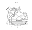
図4はクランクケース11を構成する第1ケース体11aの内側を示す正面図であり、図5は図4に示された第1ケース体11aの外側を示す正面図であり、図6は第2ケース体11bの内面を示す正面図である。第1ケース体11aは図4に示す突き当て面72に、第2ケース体11bの図6に示す突き当て面72aが突き当てられて第2ケース体11bに組み付けられるようになっている。また、第1ケース体11aの外側には、図5に示すように、これに設けられた突き当て面73に仕切り板28の突き当て面が突き当てられて、仕切り板28が組み付けられるようになっており、仕切り板28と第1ケース体11aとにより図2に示すようにチェーン室29が形成されるとともにチェーン室29から分離された第1のブリーザ通路74が図5に示すようにクランクケース11の外側に形成される。
4 is a front view showing the inside of the
第1ケース体11aには、図4および図5に示すように、クランク室65と第1のブリーザ通路74とを連通させる第1のガス導入孔75が形成されており、クランク室65内に吹き抜けたブローバイガスはクランク室65の上部に設けられたガス導入孔75から第1のブリーザ通路74内に流入する。第1ケース体11aの外面には、図5に示すように、突き当て面73と同じ高さの仕切り壁76が設けられており、この仕切り壁76により囲まれる凹部77と第1ケース体11aの外側に突き当てられる仕切り板28とにより第1のブリーザ通路74が形成されており、この第1のブリーザ通路74はガス導入孔75によりクランク室65に連通している。
As shown in FIGS. 4 and 5, the
凹部77内にはこれを二分してガス導入孔75から第1のブリーザ通路74内に流入したブローバイガスを下方に向けて案内した後に反転させて上方に案内する隔壁78が設けられ、この隔壁78によりブリーザ通路74内は下向き流れと上向き流れとに仕切られており、下向き流れの部分はオイル分離流路となっており、上向き流れの部分はガス案内流路となっている。凹部77の下部にはオイル戻し口79が第1ケース体11aの内側に連通して形成され、ブリーザ通路74の下流には第1のブリーザ通路74のガス導出孔としての連通孔80が第1ケース体11aの内側に連通して形成されている。したがって、クランク室65内のブローバイガスは、まずクランク室65の上部のガス導入孔75から第1のブリーザ通路74を形成する凹部77内に流入して下方に向けて流れた後に反転して上方のガス導出孔としての連通孔80に向けて流れることになり、オイルミストはこのブリーザ通路74を流れる過程でブローバイガスから分離されてオイル戻し口79からクランクケース11の内側に戻される一方、このブリーザ通路74においてオイルミストが分離されたブローバイガスは連通孔80からクランクケース11の内側に流入する。
In the
第1ケース体11aの内面には、図4に示すように、突き当て面72と同じ高さの仕切り壁81が設けられており、仕切り壁81と第1ケース体11aの外周壁とにより囲まれる凹部82と第2ケース体11bとにより第2のブリーザ通路83がクランクケース11の内部に形成されており、第2のブリーザ通路83は第1のブリーザ通路74のガス導出孔としての連通孔80をガス導入孔として第1のブリーザ通路74に連通しており、さらに第1のブリーザ通路74を介してクランク室65に連通している。
As shown in FIG. 4, a
凹部82内にはこれを二分してガス導入孔としての連通孔80から第2のブリーザ通路83内に流入したブローバイガスを下方に向けて案内した後に反転させて上方に案内する隔壁84が設けられ、この隔壁84によりブリーザ通路83内は下向き流れと上向き流れとに仕切られており、下向き流れの部分はオイル分離流路となっており、上向き流れの部分はガス案内流路となっている。凹部82の下部はオイル戻し流路90となっており、このオイル戻し流路90はオイル戻し口85を介してクランク室65に連通しており、ブリーザ通路83の下流は第1ケース体11aの外周壁に形成されたガス導出孔86に連通している。したがって、第1のブリーザ通路74を通過して連通孔80から第2のブリーザ通路83内に流入したブローバイガスは、隔壁84に案内されて下方に向けて流れた後に反転して上方のガス導出孔86に向けて流れることになり、オイルミストは第2のブリーザ通路83を流れる過程でブローバイガスから分離されてオイル戻し口85からクランク室65内に戻される一方、このブリーザ通路83においてオイルミストが分離されたブローバイガスはガス導出孔86からブローバイガス案内管71を介してエアクリーナ69に戻される。
A
図7は図4におけるB−B線に沿う拡大断面図であり、第2のブリーザ通路83においてブローバイガスを下向き流れから上向き流れに反転させる隔壁84の端部には、第1ケース体11aに対して鋭角となった傾斜角度θで傾斜した傾斜面87が形成されている。第1ケース体11aに突き当てて組み付けられる第2ケース体11bにも同様の隔壁84aが設けられており、この隔壁84aの端部にも同様の傾斜面87aが形成されている。それぞれの傾斜面87,87aはそれぞれ下方に向かうに従ってクランクケース11の内面に近づくように傾斜しており、第2のブリーザ通路83の内壁面に付着して隔壁84,84aの傾斜面87,87aにまで達した油滴は、ブローバイガスの流れに混入することなく、傾斜面87,87aに沿ってこれに案内されてクランクケース11の対向面つまり第1ケース体11aの内面と第2ケース体11bの内面に向けて流れることになる。これにより、ブリーザ通路83の内壁面、特に隔壁84,84aの内壁面に付着した油滴は、再度ブローバイガスに混入することなく、確実に除去されるので、ブリーザ通路83内における油滴の除去効果が向上することになる。
FIG. 7 is an enlarged cross-sectional view taken along line B-B in FIG. 4. At the end of the
同様に、第1のブリーザ通路74を形成する隔壁78の端部にも、図5に示すように傾斜面88が設けられ、第1ケース体11aに組み付けられる仕切り板28に設けられた隔壁(図示省略)にも同様の傾斜面が設けられており、ブリーザ通路74の内壁面、特にそれぞれの隔壁78の内壁面に付着した油滴は、再度ブローバイガスに混入することなく、確実に除去されるので、ブリーザ通路74内における油滴の除去効果が向上することになる。
Similarly, at the end of the
図4に示すように、ケース体11aの内面には仕切り壁91が設けられており、この仕切り壁91によりオイル戻し口79とクランク室65内のブローバイガスとの連通が遮断されるとともオイル戻し口79からの油滴をクランク室65内の潤滑油66に案内するためオイル戻し流路92が仕切り壁91により形成されている。このオイル戻し流路92は潤滑油66を介してクランク室65内に連通しているので、クランク室65内のブローバイガスは潤滑油により遮断されて直接オイル戻し口79に逆流することが防止され、オイル戻し口79からオイル戻し流路92内に流入した油滴は確実に潤滑油の油面に到達する。
As shown in FIG. 4, a
なお、図6に示すように、第2ケース体11bにも突き当て面72aの高さと同じ高さとなって仕切り壁81a,91aが形成されており、仕切り壁81aは仕切り壁81に突き当てられ、仕切り壁91aは仕切り壁91に突き当てられることになる。
As shown in FIG. 6, the
オイル戻し口85は仕切り壁81により形成されるオイル戻し流路90に連通しており、オイル戻し口85はオイル戻し口79と同様に、クランク室65内のブローバイガスとの連通が遮断されるとともにオイル戻し口85からの油滴は潤滑油66の油面に案内されるため、クランク室65内のブローバイガスは潤滑油により遮断されて直接オイル戻し口85に逆流することが防止され、オイル戻し流路90からオイル戻し口85にまで流れた油滴は確実に潤滑油の油面に到達する。
The
図示するように、本発明のブリーザ装置においては、ケース体11aの外側に第1のブリーザ通路74が形成され、内側に第2のブリーザ通路83が形成されており、クランクケース11の内側と外側を利用して二段階でブローバイガスの中の油滴を分離するようにしたので、油滴の分離効率を高めることができる。しかも、それぞれのブリーザ通路74,83において分離された油滴をクランク室65内に戻すオイル戻し口79,85にはクランク室65内のブローバイガスが逆流して流入することがないので、分離された油滴を確実にクランク室65内の潤滑油に戻すことができる。
As shown in the drawing, in the breather device of the present invention, a
本発明は前記実施の形態に限定されるものではなく、その要旨を逸脱しない範囲で種々変更可能である。たとえば、図2〜図4は図1に示される全地形走行車用のエンジンを示すが、4サイクルエンジンを駆動源とする場合であれば、汎用エンジンや乗用車用のエンジンにも本発明を適用することができる。 The present invention is not limited to the above-described embodiment, and various modifications can be made without departing from the scope of the invention. For example, FIGS. 2 to 4 show the engine for the all-terrain vehicle shown in FIG. 1, but the present invention is also applied to a general-purpose engine and an engine for a passenger car if a four-cycle engine is used as a drive source. can do.
11 クランクケース
12 クランク軸
14 シリンダ
15 シリンダヘッド
65 クランク室
66 潤滑油
67 吸気系
69 エアクリーナ
71 ブローバイガス案内管
74 第1のブリーザ通路
75 ガス導入孔
76 仕切り壁
78 隔壁
79 オイル戻し口
80 連通孔
81 仕切り壁
83 第2のブリーザ通路
84 隔壁
85 オイル戻し口
86 ガス導出孔
87 傾斜面
88 傾斜面
90 オイル戻し流路
91 仕切り壁
92 オイル戻し流路
11 Crankcase 12
Claims (2)
前記クランクケースに設けられ、ブローバイガスが流入するガス導入孔とブローバイガスを流出するガス導出孔との間に形成されるブリーザ通路と、
前記ブリーザ通路内に設けられ、前記ブリーザ通路内を下向き流れと上向き流れとに仕切る隔壁とを有し、
前記ブリーザ通路内で通路内壁面に付着した油滴を前記クランク室に戻すオイル戻し口を前記クランクケースに形成し、
前記オイル戻し口と前記クランク室内のブローバイガスとの連通を遮断して前記オイル戻し口からの油滴を前記クランク室内の潤滑油に案内する仕切り壁を前記クランクケースに設けることを特徴とするエンジンのブリーザ装置。 A crankcase that rotatably supports the crankshaft and forms a crank chamber therein;
A breather passage provided in the crankcase and formed between a gas introduction hole into which blow-by gas flows and a gas outlet hole from which blow-by gas flows out;
A partition wall provided in the breather passage and partitioning the breather passage into a downward flow and an upward flow;
An oil return port is formed in the crankcase to return oil droplets attached to the inner wall surface of the breather passage to the crank chamber in the breather passage,
An engine comprising: a partition wall provided in the crankcase that blocks communication between the oil return port and blow-by gas in the crank chamber and guides oil droplets from the oil return port to lubricating oil in the crank chamber. Breather device.
2. The engine breather apparatus according to claim 1, wherein a first breather passage having a gas introduction hole communicating with the crank chamber is formed outside the crankcase, and a gas outlet hole of the first breather passage is introduced into the gas introduction hole. A second oil breather passage serving as a hole is formed inside the crankcase; a first oil return port for returning oil droplets adhering to the inner wall surface of the passage in the first breather passage to the crank chamber; A breather device for an engine, wherein a second oil return port for returning oil drops adhering to the inner wall surface of the two breather passages to the crank chamber is guided to the lubricating oil by partition walls.
Priority Applications (1)
| Application Number | Priority Date | Filing Date | Title |
|---|---|---|---|
| JP2004111329A JP4511865B2 (en) | 2004-04-05 | 2004-04-05 | Engine breather equipment |
Applications Claiming Priority (1)
| Application Number | Priority Date | Filing Date | Title |
|---|---|---|---|
| JP2004111329A JP4511865B2 (en) | 2004-04-05 | 2004-04-05 | Engine breather equipment |
Publications (2)
| Publication Number | Publication Date |
|---|---|
| JP2005291178A true JP2005291178A (en) | 2005-10-20 |
| JP4511865B2 JP4511865B2 (en) | 2010-07-28 |
Family
ID=35324376
Family Applications (1)
| Application Number | Title | Priority Date | Filing Date |
|---|---|---|---|
| JP2004111329A Expired - Fee Related JP4511865B2 (en) | 2004-04-05 | 2004-04-05 | Engine breather equipment |
Country Status (1)
| Country | Link |
|---|---|
| JP (1) | JP4511865B2 (en) |
Cited By (2)
| Publication number | Priority date | Publication date | Assignee | Title |
|---|---|---|---|---|
| WO2009116065A3 (en) * | 2008-01-08 | 2009-11-26 | Tata Motors Limited | A novel crank case for inline two cylinder ic engine |
| CN104389691A (en) * | 2014-10-15 | 2015-03-04 | 力帆实业(集团)股份有限公司 | Engine crankcase body oil-gas separation structure |
Families Citing this family (1)
| Publication number | Priority date | Publication date | Assignee | Title |
|---|---|---|---|---|
| CN103291417B (en) * | 2013-06-28 | 2015-09-30 | 力帆实业(集团)股份有限公司 | Be arranged on the engine breathing system on crankcase body |
Citations (2)
| Publication number | Priority date | Publication date | Assignee | Title |
|---|---|---|---|---|
| JPS59139508U (en) * | 1983-03-07 | 1984-09-18 | 川崎重工業株式会社 | crank case |
| JPS63120808A (en) * | 1987-10-24 | 1988-05-25 | Yamaha Motor Co Ltd | Breather device for v-engine |
-
2004
- 2004-04-05 JP JP2004111329A patent/JP4511865B2/en not_active Expired - Fee Related
Patent Citations (2)
| Publication number | Priority date | Publication date | Assignee | Title |
|---|---|---|---|---|
| JPS59139508U (en) * | 1983-03-07 | 1984-09-18 | 川崎重工業株式会社 | crank case |
| JPS63120808A (en) * | 1987-10-24 | 1988-05-25 | Yamaha Motor Co Ltd | Breather device for v-engine |
Cited By (2)
| Publication number | Priority date | Publication date | Assignee | Title |
|---|---|---|---|---|
| WO2009116065A3 (en) * | 2008-01-08 | 2009-11-26 | Tata Motors Limited | A novel crank case for inline two cylinder ic engine |
| CN104389691A (en) * | 2014-10-15 | 2015-03-04 | 力帆实业(集团)股份有限公司 | Engine crankcase body oil-gas separation structure |
Also Published As
| Publication number | Publication date |
|---|---|
| JP4511865B2 (en) | 2010-07-28 |
Similar Documents
| Publication | Publication Date | Title |
|---|---|---|
| US7743758B2 (en) | Breather structure for internal combustion engine | |
| JP4700260B2 (en) | Continuously variable transmission | |
| CN100593077C (en) | Engine | |
| JP2008196351A (en) | Breather device for internal combustion engine | |
| WO2003085285A1 (en) | Engine | |
| US20140076268A1 (en) | Engine | |
| JP4511865B2 (en) | Engine breather equipment | |
| JP2005516148A (en) | Crankcase scavenging 4-stroke engine | |
| CN101135265B (en) | Internal combustion engine | |
| JP2009222043A (en) | Blow-by gas treatment device | |
| JP2005291176A (en) | Engine breather equipment | |
| JP2005291177A (en) | Engine breather equipment | |
| JP4291859B2 (en) | engine | |
| JP4884279B2 (en) | Internal combustion engine having a breather device | |
| JP6383094B2 (en) | Internal combustion engine | |
| JP4467916B2 (en) | Breather device for internal combustion engine | |
| JP4175816B2 (en) | Breather device for 4-stroke internal combustion engine | |
| JP4640784B2 (en) | Power unit provided with belt type transmission | |
| JPH1181934A (en) | Valve spring seat structure of internal combustion engine | |
| JP4851887B2 (en) | Internal combustion engine | |
| JP2000220434A (en) | Crankcase ventilation passage | |
| JP2005321054A (en) | Engine power transmission device | |
| JP2016191336A (en) | Oil discharge structure from crank chamber in internal combustion engine | |
| JP6623815B2 (en) | Gas-liquid separator for internal combustion engines | |
| JP2006257910A (en) | Engine breather equipment |
Legal Events
| Date | Code | Title | Description |
|---|---|---|---|
| A621 | Written request for application examination |
Free format text: JAPANESE INTERMEDIATE CODE: A621 Effective date: 20070404 |
|
| A977 | Report on retrieval |
Free format text: JAPANESE INTERMEDIATE CODE: A971007 Effective date: 20090903 |
|
| A131 | Notification of reasons for refusal |
Free format text: JAPANESE INTERMEDIATE CODE: A131 Effective date: 20090915 |
|
| A521 | Written amendment |
Free format text: JAPANESE INTERMEDIATE CODE: A523 Effective date: 20091112 |
|
| TRDD | Decision of grant or rejection written | ||
| A01 | Written decision to grant a patent or to grant a registration (utility model) |
Free format text: JAPANESE INTERMEDIATE CODE: A01 Effective date: 20100413 |
|
| A01 | Written decision to grant a patent or to grant a registration (utility model) |
Free format text: JAPANESE INTERMEDIATE CODE: A01 |
|
| A61 | First payment of annual fees (during grant procedure) |
Free format text: JAPANESE INTERMEDIATE CODE: A61 Effective date: 20100507 |
|
| FPAY | Renewal fee payment (event date is renewal date of database) |
Free format text: PAYMENT UNTIL: 20130514 Year of fee payment: 3 |
|
| R150 | Certificate of patent or registration of utility model |
Free format text: JAPANESE INTERMEDIATE CODE: R150 |
|
| FPAY | Renewal fee payment (event date is renewal date of database) |
Free format text: PAYMENT UNTIL: 20140514 Year of fee payment: 4 |
|
| R250 | Receipt of annual fees |
Free format text: JAPANESE INTERMEDIATE CODE: R250 |
|
| S531 | Written request for registration of change of domicile |
Free format text: JAPANESE INTERMEDIATE CODE: R313531 |
|
| R350 | Written notification of registration of transfer |
Free format text: JAPANESE INTERMEDIATE CODE: R350 |
|
| R250 | Receipt of annual fees |
Free format text: JAPANESE INTERMEDIATE CODE: R250 |
|
| R250 | Receipt of annual fees |
Free format text: JAPANESE INTERMEDIATE CODE: R250 |
|
| R250 | Receipt of annual fees |
Free format text: JAPANESE INTERMEDIATE CODE: R250 |
|
| S533 | Written request for registration of change of name |
Free format text: JAPANESE INTERMEDIATE CODE: R313533 |
|
| R350 | Written notification of registration of transfer |
Free format text: JAPANESE INTERMEDIATE CODE: R350 |
|
| LAPS | Cancellation because of no payment of annual fees |