JP2005291177A - Breather device for engine - Google Patents

Breather device for engine Download PDF

Info

Publication number
JP2005291177A
JP2005291177A JP2004111327A JP2004111327A JP2005291177A JP 2005291177 A JP2005291177 A JP 2005291177A JP 2004111327 A JP2004111327 A JP 2004111327A JP 2004111327 A JP2004111327 A JP 2004111327A JP 2005291177 A JP2005291177 A JP 2005291177A
Authority
JP
Japan
Prior art keywords
breather
gas
blow
case body
breather passage
Prior art date
Legal status (The legal status is an assumption and is not a legal conclusion. Google has not performed a legal analysis and makes no representation as to the accuracy of the status listed.)
Pending
Application number
JP2004111327A
Other languages
Japanese (ja)
Inventor
Toshiyuki Matsushima
俊之 松島
Current Assignee (The listed assignees may be inaccurate. Google has not performed a legal analysis and makes no representation or warranty as to the accuracy of the list.)
Subaru Corp
Original Assignee
Fuji Heavy Industries Ltd
Priority date (The priority date is an assumption and is not a legal conclusion. Google has not performed a legal analysis and makes no representation as to the accuracy of the date listed.)
Filing date
Publication date
Application filed by Fuji Heavy Industries Ltd filed Critical Fuji Heavy Industries Ltd
Priority to JP2004111327A priority Critical patent/JP2005291177A/en
Publication of JP2005291177A publication Critical patent/JP2005291177A/en
Pending legal-status Critical Current

Links

Images

Abstract

<P>PROBLEM TO BE SOLVED: To surely remove oil drops from blow-by gas returned from a crank chamber to an intake system. <P>SOLUTION: A crank case rotatably supports a crankshaft, and has a crank chamber 65 formed therein. A breather passage 83 is formed in the crank case. The breather passage communicates with a gas inlet port in which the blow-by gas from the crank chamber 65 flows, and an oil return hole 85 communicates with a lower part of the crank chamber 65. The blow-by gas passes through the breather passage 83 and then returns to the engine intake system through the gas inlet port 86. A spiral blade 87 is built into the breather passage 83 to separate the oil drops from the blow-by gas during passing through the breather passage 83. <P>COPYRIGHT: (C)2006,JPO&NCIPI

Description

本発明はピストンとシリンダとの間からクランク室に吹き抜けたブローバイガスを吸気系に戻すためのエンジンのブリーザ装置に関する。   The present invention relates to a breather device for an engine for returning blow-by gas blown into a crank chamber from between a piston and a cylinder to an intake system.

4サイクルエンジンにおいては、シリンダ内周面とピストンとの摺動部との間からクランク室内に吹き抜けたブローバイガスを吸気系に戻すようにしており、クランク室内に漏入したブローバイガスはクランク室内の潤滑油のオイルミストつまり油滴を含むので、ブローバイガスに含まれる油滴を除去するためにクランクケースにはブリーザ装置が設けられている。   In a four-cycle engine, blow-by gas blown into the crank chamber from between the cylinder inner peripheral surface and the sliding portion of the piston is returned to the intake system, and the blow-by gas leaked into the crank chamber is Since it contains oil mist of lubricating oil, that is, oil droplets, a breather device is provided in the crankcase in order to remove oil droplets contained in the blow-by gas.

クランク軸を回転自在に支持するクランクケースは、それぞれクランク軸の端部を支持する2つのケース体を突き合わせた状態で相互に組み付けることにより形成されており、従来のブリーザ装置には、特許文献1に記載されるように、一方のケース体にブリーザ室を形成し、このブリーザ室に連通管によりクランク室内のブローバイガスを案内し、ブリーザ室で直角に流れの向きを変えてブローバイガスに含まれる油滴を分離するようにしたものがある。また、従来のブリーザ装置には、特許文献2に記載されるように、シリンダライナとクランクケースとの間に隙間を形成し、その隙間に連通する導入孔を一方のケース体に形成し、他方のケース体に設けられた導出孔との間にブリーザ室を形成するようにしたものがある。
特開2001−65326号公報 特開2002−256838号公報
A crankcase that rotatably supports the crankshaft is formed by assembling two case bodies that respectively support the end portions of the crankshaft, and a conventional breather device is disclosed in Patent Document 1. As described in the above, a breather chamber is formed in one case body, the blow-by gas in the crank chamber is guided to the breather chamber by a communication pipe, and the flow direction is changed at a right angle in the breather chamber and is included in the blow-by gas. There is one that separates oil droplets. Further, in the conventional breather device, as described in Patent Document 2, a gap is formed between the cylinder liner and the crankcase, an introduction hole communicating with the gap is formed in one case body, and the other In some cases, a breather chamber is formed between the lead hole provided in the case body.
JP 2001-65326 A JP 2002-256838 A

しかしながら、従来のようにシリンダライナとクランクケースとの間からブローバイガスをブリーザ室に案内するようにすると、導入孔と導出孔との間のブリーザ室の長さを十分に確保することができないので、クランク室内のブローバイガスに含まれる油滴を十分に取り除くことができない。また、ブリーザ室内のブローバイガスをブリーザ室で直角に案内してそのまま吸気系に案内するだけでは、十分に油滴を除去することができない。このため、従来のブリーザ装置においては、オイル戻りが悪くなり、クランク室内に供給するオイル量を増加する必要がある。さらに、従来のように、クランクケースの側部にブリーザ室を設けるようにすると、エンジンの幅寸法が大きくなるという問題点がある。   However, if the blow-by gas is guided to the breather chamber from between the cylinder liner and the crankcase as in the prior art, the length of the breather chamber between the inlet hole and the outlet hole cannot be sufficiently secured. The oil droplets contained in the blow-by gas in the crank chamber cannot be removed sufficiently. Moreover, oil droplets cannot be sufficiently removed by merely guiding the blow-by gas in the breather chamber at a right angle in the breather chamber and guiding it directly to the intake system. For this reason, in the conventional breather device, the oil return is poor, and it is necessary to increase the amount of oil supplied to the crank chamber. Further, when the breather chamber is provided at the side of the crankcase as in the conventional case, there is a problem that the width of the engine increases.

本発明の目的は、クランク室から吸気系に戻されるブローバイガスから確実に油滴を除去し得るようにすることにある。   An object of the present invention is to enable oil droplets to be reliably removed from blow-by gas returned from the crank chamber to the intake system.

本発明の他の目的は、クランクケースを大型化することなく、確実にブローバイガスから油滴を除去し得るようにすることにある。   Another object of the present invention is to reliably remove oil droplets from blow-by gas without increasing the size of the crankcase.

本発明のエンジンのブリーザ装置は、第1ケース体と当該第1ケース体に突き合わせられる第2ケース体とを有し、クランク軸を回転自在に支持するとともに内部にクランク室を形成するクランクケースと、前記第1ケース体と第2ケース体とにより形成され、前記クランク室内のブローバイガスが流入するガス導入口を、前記クランク室の下部に連通するオイル戻し口に連通するとともに、ブローバイガスを外部に案内するガス導出孔に連通するブリーザ通路と、前記ブリーザ通路に組み込まれ、当該ブリーザ通路を流れるブローバイガスを螺旋状に案内する螺旋羽根とを有することを特徴とする。   A breather device for an engine according to the present invention includes a first case body and a second case body that is abutted against the first case body, rotatably supporting a crankshaft and forming a crank chamber therein. A gas inlet formed by the first case body and the second case body, into which blow-by gas in the crank chamber flows, communicates with an oil return port that communicates with a lower portion of the crank chamber; A breather passage communicating with the gas outlet hole for guiding the gas and a spiral blade incorporated in the breather passage and spirally guiding the blow-by gas flowing through the breather passage.

本発明のエンジンのブリーザ装置は、内周面に複数の環状凹部が形成され、前記螺旋羽根を収容する蛇腹状のブリーザケースを有し、当該ブリーザケースの内部にブローバイガスを案内することを特徴とする。   A breather device for an engine according to the present invention is characterized in that a plurality of annular recesses are formed on an inner peripheral surface, and has a bellows-like breather case that accommodates the spiral blade, and guides blow-by gas into the breather case. And

本発明のエンジンのブリーザ装置は、前記ブリーザ通路を前記第1ケース体と前記第2ケース体の突き当て面に沿わせて形成することを特徴とする。   The breather device for an engine according to the present invention is characterized in that the breather passage is formed along the abutting surfaces of the first case body and the second case body.

本発明のエンジンのブリーザ装置は、前記ブリーザ通路を前記第1ケース体と前記第2ケース体の突き当て面を横断させて形成することを特徴とする。   The breather device for an engine according to the present invention is characterized in that the breather passage is formed across the abutting surfaces of the first case body and the second case body.

本発明によれば、ブリーザ通路にはこの中を流れるブローバイガスを螺旋状に案内する螺旋羽根が組み込まれているので、狭いスペースの中で長いブリーザ通路を形成することができ、ブローバイガスに含まれる油滴を除去することができる。ブローバイガスが螺旋羽根に沿って流れると、ブローバイガスに含まれる液滴は遠心力を受けてブリーザ通路の内周面に付着することになり、液滴を確実に除去することができる。また、通路内で液滴を取り除くようにしたので、クランクケースの幅寸法を大きくすることなく、液滴を確実に除去することができる。   According to the present invention, the breather passage incorporates spiral blades that guide the blow-by gas flowing through the breather passage in a spiral manner, so that a long breather passage can be formed in a narrow space. Oil droplets can be removed. When the blowby gas flows along the spiral blades, the droplets contained in the blowby gas receive centrifugal force and adhere to the inner peripheral surface of the breather passage, so that the droplets can be reliably removed. In addition, since the droplets are removed in the passage, the droplets can be reliably removed without increasing the width of the crankcase.

以下、本発明の実施の形態を図面に基づいて詳細に説明する。図1はバギー車とも言われるATVつまり全地形走行車の一例を示す斜視図であり、車体1には前輪2a,2bと後輪3a,3bが設けられており、鞍乗り型の座席4が車体1の中央部に設けられている。座席4に着座した乗員はハンドル5を操作して走行することになる。   Hereinafter, embodiments of the present invention will be described in detail with reference to the drawings. FIG. 1 is a perspective view showing an example of an ATV, which is also called a buggy vehicle, that is, an all-terrain vehicle. The vehicle body 1 is provided with front wheels 2a and 2b and rear wheels 3a and 3b. It is provided at the center of the vehicle body 1. An occupant seated in the seat 4 travels by operating the handle 5.

図2は図1に示された全地形走行車に搭載される動力伝達装置を示す概略図であり、図3は図2におけるA−A線に沿う方向の断面図である。図2に示すように、第1ケース体11aと第2ケース体11bとを突き合わせて組み立てられるクランクケース11にはクランク軸12が回転自在に装着されるとともに、図3に示すようにエンジン13が取り付けられている。エンジン13は、図3に示すように、クランクケース11に固定されるシリンダ14と、このシリンダ14の上端に固定されるシリンダヘッド15とを有している。シリンダ14に形成されたシリンダボア内にはピストン16が往復動自在に組み込まれ、クランク軸12にその回転中心から偏心した位置に固定されたクランクピン17とピストン16との間にはコネクティングロッド18が連結され、エンジン13によりクランク軸12は回転駆動される。   2 is a schematic view showing a power transmission device mounted on the all-terrain vehicle shown in FIG. 1, and FIG. 3 is a cross-sectional view taken along the line AA in FIG. As shown in FIG. 2, a crankshaft 12 is rotatably mounted on the crankcase 11 assembled by abutting the first case body 11a and the second case body 11b, and the engine 13 is mounted as shown in FIG. It is attached. As shown in FIG. 3, the engine 13 has a cylinder 14 fixed to the crankcase 11 and a cylinder head 15 fixed to the upper end of the cylinder 14. A piston 16 is incorporated in a cylinder bore formed in the cylinder 14 so as to freely reciprocate, and a connecting rod 18 is interposed between the piston 16 and the crankpin 17 fixed to the crankshaft 12 at a position eccentric from the center of rotation. The crankshaft 12 is driven to rotate by the engine 13.

図3に示すように、シリンダヘッド15には燃焼室19に開口して吸気ポート21aが形成され、この吸気ポート21aを開閉するための吸気弁22aがシリンダヘッド15に装着されている。また、シリンダヘッド15には燃焼室19に開口して排気ポート21bが形成され、この排気ポート21bを開閉するための排気弁22bがシリンダヘッド15に装着されている。シリンダヘッド15には、カムシャフト23が回転自在に装着され、これと平行に設けられたロッカシャフト24には、吸気弁22aを開閉駆動するためのロッカアーム25aと、排気弁22bを開閉駆動するためのロッカアーム25bとが回動自在に装着されている。   As shown in FIG. 3, the cylinder head 15 is formed with an intake port 21 a that opens into the combustion chamber 19, and an intake valve 22 a for opening and closing the intake port 21 a is attached to the cylinder head 15. The cylinder head 15 has an exhaust port 21b that opens into the combustion chamber 19, and an exhaust valve 22b for opening and closing the exhaust port 21b is mounted on the cylinder head 15. A camshaft 23 is rotatably mounted on the cylinder head 15, and a rocker arm 24a for opening / closing the intake valve 22a and an exhaust valve 22b for opening / closing the rocker shaft 24 provided in parallel therewith. The rocker arm 25b is rotatably mounted.

図2に示すように、クランク軸12にはスプロケット26が固定され、カムシャフト23に固定された図示しないスプロケットとの間にはタイミングチェーン(図示省略)が掛け渡されており、吸気弁22aと排気弁22bはクランク軸12の回転によりカムシャフト23およびロッカアーム25a,25bを介して所定のタイミングで開閉駆動される。タイミングチェーンは、図2に示すように、第1ケース体11aの外側に取り付けられる仕切り板28と第1ケース体11aとにより形成されるチェーン室29内に配置されている。   As shown in FIG. 2, a sprocket 26 is fixed to the crankshaft 12, and a timing chain (not shown) is spanned between a sprocket (not shown) fixed to the camshaft 23, and an intake valve 22 a The exhaust valve 22b is driven to open and close at a predetermined timing through the camshaft 23 and the rocker arms 25a and 25b as the crankshaft 12 rotates. As shown in FIG. 2, the timing chain is arranged in a chain chamber 29 formed by a partition plate 28 attached to the outside of the first case body 11a and the first case body 11a.

図3に示すエンジン13は図1に示す全地形走行車の駆動源として使用されており、図2に示すように、クランクケース11には変速機ケース31が取り付けられ、この変速機ケース31の内部にはベルト式の無段変速機32が組み込まれている。無段変速機32はクランク軸12に同軸状となって変速機ケース31内に回転自在に装着されるプライマリ軸33と、このプライマリ軸33に平行となって回転自在に変速機ケース31内に回転自在に装着されるセカンダリ軸34とを有し、プライマリ軸33はこれとクランク軸12との間に組み込まれる遠心クラッチ35のクラッチドラム36に連結されている。   The engine 13 shown in FIG. 3 is used as a drive source for the all-terrain vehicle shown in FIG. 1. As shown in FIG. 2, a transmission case 31 is attached to the crankcase 11. A belt-type continuously variable transmission 32 is incorporated inside. The continuously variable transmission 32 is coaxial with the crankshaft 12 and is rotatably mounted in the transmission case 31 and in the transmission case 31 in parallel with the primary shaft 33. The primary shaft 33 is connected to a clutch drum 36 of a centrifugal clutch 35 incorporated between the secondary shaft 34 and the crankshaft 12.

プライマリ軸33には溝幅可変のプライマリプーリ37が組み付けられ、セカンダリ軸34には溝幅可変のセカンダリプーリ38が組み付けられている。これらのプーリ37,38の間には、ゴム製のVベルト39が掛け渡されており、Vベルト39のプライマリプーリ37とセカンダリプーリ38とに対する巻き付け径が変化すると、プライマリ軸33の回転は無段階に変速比が変化してセカンダリ軸34に伝達される。プライマリプーリ37には、プライマリ軸33に固定されたカムプレート41により、プライマリ軸33の回転中心に対して直角方向を向いて円柱形状の遠心ウエイト42が複数個装着されており、セカンダリ軸34には、Vベルト39への締め付け力を加えるために、圧縮コイルばね43が装着されている。   A primary pulley 37 with a variable groove width is assembled to the primary shaft 33, and a secondary pulley 38 with a variable groove width is assembled to the secondary shaft 34. Between these pulleys 37 and 38, a rubber V-belt 39 is stretched. When the winding diameter of the V-belt 39 around the primary pulley 37 and the secondary pulley 38 changes, the primary shaft 33 does not rotate. The gear ratio changes in stages and is transmitted to the secondary shaft 34. A plurality of columnar centrifugal weights 42 are mounted on the primary pulley 37 so as to be perpendicular to the rotation center of the primary shaft 33 by cam plates 41 fixed to the primary shaft 33. In order to apply a tightening force to the V-belt 39, a compression coil spring 43 is mounted.

したがって、クランク軸12が所定以上の回転数となって遠心クラッチ35を介してプライマリ軸33とクランク軸12とが締結された状態のもとで、プライマリ軸33の回転数が高くなると、遠心ウエイト42はこれに加わる遠心力により径方向外方に向けて移動し、プライマリプーリ37の溝幅が狭められてこのプーリ37に対する巻き付け径が大きくなる。これにより、セカンダリプーリ38の溝幅がばね力に抗して広がってVベルト39のセカンダリプーリ38に対する巻き付け径が小さくなり、無段変速機32の変速比は高速段側に変化する。   Therefore, when the rotation speed of the primary shaft 33 becomes high with the crankshaft 12 rotating at a predetermined speed or higher and the primary shaft 33 and the crankshaft 12 are fastened via the centrifugal clutch 35, the centrifugal weight is increased. 42 moves outward in the radial direction by the centrifugal force applied thereto, the groove width of the primary pulley 37 is narrowed, and the winding diameter of the pulley 37 is increased. As a result, the groove width of the secondary pulley 38 expands against the spring force, the winding diameter of the V belt 39 around the secondary pulley 38 is reduced, and the gear ratio of the continuously variable transmission 32 changes to the high speed stage side.

変速機ケース31には図2に示すようにギヤケース44が組み付けられ、このギヤケース44にはセカンダリ軸34が支持されるとともに、セカンダリ軸34に平行となって出力軸45が回転自在に装着され、さらに出力軸45に平行となって車軸46が回転自在に装着されており、車軸46は図1に示した後輪3a,3bに直接連結されている。セカンダリ軸34と出力軸45との間には、セカンダリ軸34に一体に設けられた歯車と出力軸45に回転自在に装着された歯車とからなる正転用の歯車列47が設けられるとともに、セカンダリ軸34に一体に設けられた歯車と出力軸45に回転自在に装着される歯車とこれに噛み合う図示しないアイドラー歯車とからなる逆転用の歯車列48が設けられている。   As shown in FIG. 2, a gear case 44 is assembled to the transmission case 31, and a secondary shaft 34 is supported on the gear case 44, and an output shaft 45 is rotatably mounted in parallel with the secondary shaft 34, Further, an axle 46 is rotatably mounted parallel to the output shaft 45, and the axle 46 is directly connected to the rear wheels 3a and 3b shown in FIG. Between the secondary shaft 34 and the output shaft 45, there is provided a forward rotation gear train 47 including a gear integrally provided on the secondary shaft 34 and a gear rotatably mounted on the output shaft 45. A reverse gear train 48 is provided which includes a gear integrally provided on the shaft 34, a gear rotatably mounted on the output shaft 45, and an idler gear (not shown) meshing with the gear.

出力軸45の回転方向を正転方向と逆転方向に切り換えるために、出力軸45には前後進切換機構49が装着されている。前後進切換機構49は、図2に示すように、出力軸45に設けられたスプラインにそれぞれ噛み合う切換ディスク51a,51bを有しており、これらの切換ディスク51a,51bは出力軸45に軸方向に摺動自在に装着されている。切換ディスク51aを歯車列47に係合させると、セカンダリ軸34の回転は正転方向となって車軸46に伝達され車両は前進移動する。一方、切換ディスク51bを歯車列48に係合させると、セカンダリ軸34の回転は逆転方向となって車軸46に伝達され、車両は後退移動する。   In order to switch the rotation direction of the output shaft 45 between the forward rotation direction and the reverse rotation direction, a forward / reverse switching mechanism 49 is mounted on the output shaft 45. As shown in FIG. 2, the forward / reverse switching mechanism 49 includes switching disks 51 a and 51 b that respectively mesh with splines provided on the output shaft 45, and these switching disks 51 a and 51 b are axially connected to the output shaft 45. It is slidably attached to. When the switching disk 51a is engaged with the gear train 47, the rotation of the secondary shaft 34 is transmitted in the forward direction to the axle 46 and the vehicle moves forward. On the other hand, when the switching disk 51b is engaged with the gear train 48, the rotation of the secondary shaft 34 is transmitted in the reverse direction to the axle 46, and the vehicle moves backward.

図2に示すように、クランクケース11にはクランク軸12に平行にバランサ軸52が回転自在に装着され、バランサ軸52は歯車列53を介してクランク軸12に連結されている。バランサ軸52にはバランスウエイト54が一体に設けられるとともに、クランクケース11に装着されたオイルポンプ55のロータに連結されており、このオイルポンプ55から吐出される潤滑油は、動力伝達装置における摺動部に図示しない油路を介して供給されるようになっている。   As shown in FIG. 2, a balancer shaft 52 is rotatably mounted on the crankcase 11 in parallel with the crankshaft 12, and the balancer shaft 52 is connected to the crankshaft 12 through a gear train 53. A balance weight 54 is integrally provided on the balancer shaft 52, and is connected to a rotor of an oil pump 55 mounted on the crankcase 11. The lubricating oil discharged from the oil pump 55 is slid in the power transmission device. The moving part is supplied through an oil passage (not shown).

クランクケース11には、図2に示すように、発電体ケース56が取り付けられており、発電体ケース56内には発電体57が装着されるようになっており、発電体57はクランク軸12に取り付けられるアウターロータ58と、クランクケース11に取り付けられるステータ59とを有している。したがって、エンジン13が駆動されてクランク軸12が回転すると、発電体57により発電された電力が図示しないバッテリに充電される。   As shown in FIG. 2, a power generator case 56 is attached to the crankcase 11, and a power generator 57 is mounted in the power generator case 56, and the power generator 57 is connected to the crankshaft 12. And an outer rotor 58 attached to the crankcase 11 and a stator 59 attached to the crankcase 11. Therefore, when the engine 13 is driven and the crankshaft 12 rotates, the electric power generated by the power generator 57 is charged in a battery (not shown).

エンジンを始動させるために、発電体ケース56内にはスタータ61が装着され、このスタータ61はクランクケース11に取り付けられた電動モータ62により駆動されるようになっている。バッテリの充電量が不足してエンジン13をスタータ61により始動できないときに、手動でエンジン13を始動させるために、発電体ケース56内にはリコイルスタータ63が装着されている。リコイルスタータ63は、リコイルロープが巻き付けられたリコイルプーリ64を有し、リコイルロープを引いてリコイルプーリ64を回転させるとクランク軸12が回転し、エンジン13を手動でも始動させることができる。   In order to start the engine, a starter 61 is mounted in the power generator case 56, and the starter 61 is driven by an electric motor 62 attached to the crankcase 11. A recoil starter 63 is mounted in the power generator case 56 in order to start the engine 13 manually when the charge amount of the battery is insufficient and the engine 13 cannot be started by the starter 61. The recoil starter 63 has a recoil pulley 64 around which a recoil rope is wound. When the recoil rope 64 is pulled and the recoil pulley 64 is rotated, the crankshaft 12 rotates and the engine 13 can be started manually.

クランクケース11は、図2に示すように、発電体57側の第1ケース体11aと、無段変速機32側の第2ケース体11bとからなり、これらを突き合わせることにより組み立てられており、内部のクランク室65には図3に示すように、潤滑油66が収容されている。潤滑油66は図示しないオイルフィルタを介してオイルポンプ55に供給されるとともに、クランクケース11内に組み込まれた部材相互の摺動部に供給される。   As shown in FIG. 2, the crankcase 11 includes a first case body 11a on the power generation body 57 side and a second case body 11b on the continuously variable transmission 32 side, and is assembled by abutting them together. As shown in FIG. 3, lubricating oil 66 is accommodated in the internal crank chamber 65. Lubricating oil 66 is supplied to an oil pump 55 through an oil filter (not shown) and is also supplied to sliding portions between members incorporated in the crankcase 11.

クランク室65内には、燃焼室19内に供給された混合気を図示しない点火プラグにより点火して混合気の燃焼によりピストン16がクランク軸12に向けて押し下げられるときに、燃焼ガスがピストンリングとシリンダボアとの間から吹き抜けて僅かに漏入する。クランク室65に吹き抜けて漏入したブローバイガスは、HCやCOなどの未燃焼成分、およびCO2などの燃焼成分を含んでおり、クランク室65内のブローバイガスを図3に示す吸気系67に戻すようにしている。   In the crank chamber 65, when the air-fuel mixture supplied into the combustion chamber 19 is ignited by a spark plug (not shown) and the piston 16 is pushed down toward the crankshaft 12 by combustion of the air-fuel mixture, the combustion gas is moved into the piston ring. Blows through between the cylinder bore and slightly leaks. The blow-by gas leaked through the crank chamber 65 contains unburned components such as HC and CO and combustion components such as CO 2, and the blow-by gas in the crank chamber 65 is returned to the intake system 67 shown in FIG. I am doing so.

吸気系67は、外気を吸気ポート21aに案内する吸気通路68を有しており、吸気通路68には吸気通路68の空気流入口から流入された外気に含まれるゴミなどの異物を除去して浄化するためのエアクリーナ69と、浄化された外気に燃料タンクから供給された燃料を噴霧して混合気を生成するための気化器70とが設けられている。クランクケース11とエアクリーナ69との間にはブローバイガス案内管71が設けられており、クランク室65内のブローバイガスはブローバイガス案内管71を介してエアクリーナ69のクリーンサイドに戻されて吸気系67に再循環される。クランク室65に流入したブローバイガスには、クランク室65内に収容された潤滑油が飛散するので、ブローバイガス案内管71に入り込むブローバイガスには油成分つまりオイルミストが含まれるおそれがあり、クランク室65内で油成分とブローバイガスとを分離してブローバイガスのみを吸気系67に戻す必要がある。   The intake system 67 has an intake passage 68 that guides outside air to the intake port 21a. The intake passage 68 removes foreign matters such as dust contained in the outside air flowing in from the air inlet of the intake passage 68. An air cleaner 69 for purifying, and a vaporizer 70 for spraying the fuel supplied from the fuel tank to the purified outside air to generate an air-fuel mixture are provided. A blow-by gas guide pipe 71 is provided between the crankcase 11 and the air cleaner 69, and the blow-by gas in the crank chamber 65 is returned to the clean side of the air cleaner 69 via the blow-by gas guide pipe 71 to be an intake system 67. Will be recycled. Since the lubricating oil contained in the crank chamber 65 is scattered in the blow-by gas flowing into the crank chamber 65, the blow-by gas entering the blow-by gas guide pipe 71 may contain an oil component, that is, oil mist. It is necessary to separate the oil component and the blow-by gas in the chamber 65 and return only the blow-by gas to the intake system 67.

図4はクランクケース11を構成する第1ケース体11aの内側を示す正面図であり、図5は図4に示された第1ケース体11aの外側を示す正面図である。第1ケース体11aは図4に示す突き当て面72に第2ケース体11bの突き当て面が突き当てられて第2ケース体11bに組み付けられるようになっている。また、第1ケース体11aの外側には、図5に示すように、これに設けられた突き当て面73に仕切り板28の突き当て面が突き当てられて、仕切り板28が組み付けられるようになっており、仕切り板28と第1ケース体11aとにより図2に示すようにチェーン室29が形成されるとともにチェーン室29から分離された第1のブリーザ通路74が図5に示すように形成される。   4 is a front view showing the inside of the first case body 11a constituting the crankcase 11, and FIG. 5 is a front view showing the outside of the first case body 11a shown in FIG. The first case body 11a is assembled to the second case body 11b by abutting the abutting surface of the second case body 11b against the abutting surface 72 shown in FIG. Moreover, as shown in FIG. 5, the abutment surface of the partition plate 28 is abutted against the abutment surface 73 provided on the outside of the first case body 11a so that the partition plate 28 is assembled. The partition plate 28 and the first case body 11a form the chain chamber 29 as shown in FIG. 2, and the first breather passage 74 separated from the chain chamber 29 is formed as shown in FIG. Is done.

第1ケース体11aには、図4および図5に示すように、クランク室65と第1のブリーザ通路74とを連通させる第1のガス導入孔75が形成されており、クランク室65内に吹き抜けたブローバイガスはクランク室65の上部に設けられたガス導入孔75から第1のブリーザ通路74内に流入する。第1ケース体11aの外面には、図5に示すように、突き当て面73と同じ高さの仕切り壁76が設けられており、この仕切り壁76により囲まれる凹部77と第1ケース体11aの外側に突き当てられる仕切り板28とにより第1のブリーザ通路74が形成されており、この第1のブリーザ通路74はガス導入孔75によりクランク室65に連通している。   As shown in FIGS. 4 and 5, the first case body 11 a is formed with a first gas introduction hole 75 that allows the crank chamber 65 and the first breather passage 74 to communicate with each other. The blow-by gas blown through flows into the first breather passage 74 from a gas introduction hole 75 provided in the upper portion of the crank chamber 65. As shown in FIG. 5, a partition wall 76 having the same height as the abutting surface 73 is provided on the outer surface of the first case body 11a. The recess 77 surrounded by the partition wall 76 and the first case body 11a. A first breather passage 74 is formed by the partition plate 28 abutted on the outer side of the first breather passage, and the first breather passage 74 communicates with the crank chamber 65 through a gas introduction hole 75.

凹部77内にはこれを二分してガス導入孔75から第1のブリーザ通路74内に流入したブローバイガスを下方に向けて案内した後に反転させて上方に案内する隔壁78が設けられ、この隔壁78により第1のブリーザ通路74内は下向き流れと上向き流れとに仕切られており、下向き流れの部分はオイル分離流路となっており、上向き流れの部分はガス案内流路となっている。凹部77の下部にはオイル戻し口79が第1ケース体11aの内側に連通して形成され、第1のブリーザ通路74の下流には第1のブリーザ通路74のガス導出孔としての連通孔80が第1ケース体11aの内側に連通して形成されている。したがって、クランク室65内のブローバイガスは、まずクランク室65の上部のガス導入孔75から第1のブリーザ通路74を形成する凹部77内に流入して下方に向けて流れた後に反転して上方のガス導出孔としての連通孔80に向けて流れることになり、オイルミストはこのブリーザ通路74を流れる過程でブローバイガスから分離されてオイル戻し口79からクランクケース11の内側に戻される一方、このブリーザ通路74においてオイルミストが分離されたブローバイガスは連通孔80からクランクケース11の内側に流入する。   In the recess 77, there is provided a partition wall 78 which bisects this and guides the blow-by gas flowing into the first breather passage 74 from the gas introduction hole 75 downward and then reverses and guides it upward. 78, the inside of the first breather passage 74 is partitioned into a downward flow and an upward flow, the downward flow portion is an oil separation flow path, and the upward flow portion is a gas guide flow path. An oil return port 79 is formed in the lower portion of the recess 77 so as to communicate with the inside of the first case body 11 a, and a communication hole 80 as a gas outlet hole of the first breather passage 74 is formed downstream of the first breather passage 74. Is formed in communication with the inside of the first case body 11a. Therefore, the blow-by gas in the crank chamber 65 first flows into the recess 77 forming the first breather passage 74 from the gas introduction hole 75 in the upper part of the crank chamber 65, flows downward, and then reverses and moves upward. The oil mist is separated from the blow-by gas in the course of flowing through the breather passage 74 and returned from the oil return port 79 to the inside of the crankcase 11. The blow-by gas from which the oil mist is separated in the breather passage 74 flows into the crankcase 11 from the communication hole 80.

第1ケース体11aの内面には、図4に示すように、突き当て面72と同じ高さの仕切り壁81が設けられており、仕切り壁81と第1ケース体11aの外周壁とにより囲まれる凹部82と第2ケース体11bとにより第2のブリーザ通路83がクランクケース11の内部に形成されており、第2のブリーザ通路83は第1のブリーザ通路74のガス導出孔としての連通孔80をガス導入孔として第1のブリーザ通路74に連通しており、さらに第1のブリーザ通路74を介してクランク室65に連通している。   As shown in FIG. 4, a partition wall 81 having the same height as the abutting surface 72 is provided on the inner surface of the first case body 11a, and is surrounded by the partition wall 81 and the outer peripheral wall of the first case body 11a. The second breather passage 83 is formed in the crankcase 11 by the recessed portion 82 and the second case body 11b, and the second breather passage 83 is a communication hole as a gas outlet hole of the first breather passage 74. A gas introduction hole 80 communicates with the first breather passage 74, and further communicates with the crank chamber 65 through the first breather passage 74.

凹部82内にはこれを二分してガス導入孔としての連通孔80から第2のブリーザ通路83内に流入したブローバイガスを下方に向けて案内した後に反転させて上方に案内する隔壁84が設けられ、この隔壁84により第2のブリーザ通路83内は下向き流れと上向き流れとに仕切られており、下向き流れの部分はオイル分離流路となっており、上向き流れの部分はガス案内流路となっている。凹部82の下部はオイル戻し流路90となっており、このオイル戻し流路90はオイル戻し口85を介してクランク室65に連通しており、第2のブリーザ通路83の下流は第1ケース体11aの外周壁に形成されたガス導出孔86に連通している。したがって、第1のブリーザ通路74を通過して連通孔80から第2のブリーザ通路83内に流入したブローバイガスは、隔壁84に案内されて下方に向けて流れた後に反転して上方のガス導出孔86に向けて流れることになり、オイルミストは第2のブリーザ通路83を流れる過程でブローバイガスから分離されてオイル戻し口85からクランク室65内に戻される一方、第2のブリーザ通路83においてオイルミストが分離されたブローバイガスはガス導出孔86からブローバイガス案内管71を介してエアクリーナ69に戻される。   A partition wall 84 is provided in the recess 82. The partition wall 84 bisects the blow-by gas that flows into the second breather passage 83 from the communication hole 80 serving as a gas introduction hole and guides the blow-by gas downward. The partition wall 84 divides the inside of the second breather passage 83 into a downward flow and an upward flow. The downward flow portion is an oil separation passage, and the upward flow portion is a gas guide passage. It has become. The lower portion of the recess 82 is an oil return passage 90, which communicates with the crank chamber 65 through an oil return port 85, and the second breather passage 83 is downstream of the first case. It communicates with a gas outlet hole 86 formed in the outer peripheral wall of the body 11a. Accordingly, the blowby gas that has passed through the first breather passage 74 and has flowed into the second breather passage 83 from the communication hole 80 is guided by the partition wall 84 and flows downward, and then reverses to escape the upper gas. The oil mist is separated from the blow-by gas in the process of flowing through the second breather passage 83 and returned to the crank chamber 65 from the oil return port 85, while in the second breather passage 83. The blow-by gas from which the oil mist has been separated is returned to the air cleaner 69 from the gas outlet hole 86 through the blow-by gas guide pipe 71.

第2のブリーザ通路83のうち下流側のガス案内流路にはこの中を流れるブローバイガスを螺旋状に案内する螺旋羽根87が組み込まれており、この螺旋羽根87はブリーザケース88内に組み込まれている。   A spiral blade 87 that guides the blow-by gas flowing in the second breather passage 83 in a spiral manner is incorporated in the gas guide passage on the downstream side, and the spiral blade 87 is incorporated in the breather case 88. ing.

図6(A)は螺旋羽根87を示す斜視図であり、図6(B)は螺旋羽根を収容するブリーザケース88を示す斜視図である。螺旋羽根87は中心部の軸部87aと螺旋状の羽根部87bとを有し、これらが一体となって形成されている。この螺旋羽根87を収容するブリーザケース88は全体的に円筒形状となっており内周面に複数の環状凹部88aが形成され、このブリーザケース88内に螺旋羽根87を組み込むと羽根部87bの外周面がブリーザケース88の内周面に対して傾斜して接触するので、羽根部87bと環状凹部88aとの間にはブローバイガスが流れる隙間が形成されることになる。したがって、第2のブリーザ通路83内を流れるブローバイガスは螺旋羽根87によって螺旋状に旋回しながらガス導出孔86に向けて流れるので、ブローバイガスの中に含まれる油滴は遠心力を受けてブリーザケース88の環状凹部88a内に入り込み、ブリーザケース88の内周面に沿って下方に流れてオイル戻し口85からクランク室65内に戻されることになる。しかも、第2のブリーザ通路83内には螺旋羽根87により螺旋状に長い通路が形成されるので、狭いスペースの中にブローバイガスが接触する広い面積を形成することができ、ブローバイガスの中の液滴を確実に取り除くことができる。   FIG. 6A is a perspective view showing a spiral blade 87, and FIG. 6B is a perspective view showing a breather case 88 that houses the spiral blade. The spiral blade 87 has a central shaft portion 87a and a spiral blade portion 87b, which are integrally formed. The breather case 88 that accommodates the spiral blade 87 has a generally cylindrical shape, and a plurality of annular recesses 88a are formed on the inner peripheral surface. When the spiral blade 87 is incorporated in the breather case 88, the outer periphery of the blade portion 87b is formed. Since the surface is inclined to contact with the inner peripheral surface of the breather case 88, a gap through which blow-by gas flows is formed between the blade portion 87b and the annular recess 88a. Accordingly, the blow-by gas flowing in the second breather passage 83 flows toward the gas outlet hole 86 while being spirally swirled by the spiral blade 87, so that the oil droplets contained in the blow-by gas receive a centrifugal force and receive the breather. The air enters the annular recess 88 a of the case 88, flows downward along the inner peripheral surface of the breather case 88, and is returned from the oil return port 85 into the crank chamber 65. In addition, since a long spiral path is formed by the spiral blade 87 in the second breather path 83, a wide area where the blow-by gas contacts can be formed in a narrow space. The droplets can be surely removed.

図4に示すように、オイル戻し口79はクランク室65に直接開口されているが、このオイル戻し口79をクランク室65から仕切り壁により仕切ることにより、オイル戻し口79から液滴が直接クランク室65内に流入しないようにしても良い。   As shown in FIG. 4, the oil return port 79 is directly open to the crank chamber 65. By partitioning the oil return port 79 from the crank chamber 65 by a partition wall, droplets are directly cranked from the oil return port 79. It may not be allowed to flow into the chamber 65.

図4および図5に示すように、クランク室65内のブローバイガスをまずクランクケース11の外側の第1のブリーザ通路74内に案内した後に、クランクケース11の内側の第2のブリーザ通路83内に案内するようにしているので、クランクケース11を介して外側に流れた後に内側に戻る流れにより油滴が除去され、さらにブリーザ通路83において最終的に油滴が除去されることになる。ただし、クランクケース11の外側に第1のブリーザ通路74を設けることなく、仕切り壁81に連通孔80を形成し、クランク室65から第2のブリーザ通路83にその上端部から直接ブローバイガスを供給するようにしても良い。また、第1のブリーザ通路74に螺旋羽根87とブリーザケース88とを組み込むようにしても良い。   As shown in FIGS. 4 and 5, the blow-by gas in the crank chamber 65 is first guided into the first breather passage 74 outside the crankcase 11 and then inside the second breather passage 83 inside the crankcase 11. Therefore, the oil droplets are removed by the flow returning to the inside after flowing outward through the crankcase 11, and the oil droplets are finally removed in the breather passage 83. However, without providing the first breather passage 74 outside the crankcase 11, the communication hole 80 is formed in the partition wall 81, and blow-by gas is supplied directly from the upper end portion to the second breather passage 83 from the crank chamber 65. You may make it do. Further, the spiral blade 87 and the breather case 88 may be incorporated in the first breather passage 74.

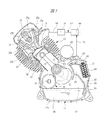
図7は本発明の他の実施の形態であるブリーザ装置を示す正面図であり、図8は図7におけるB−B線に沿う断面図である。これらの図においては、図2〜図6に示した部材と共通する部材には同一の符号が付されており、図7は前述した実施の形態の図4と同様にケース体11aの内面を示す。図8に示すように、第1ケース体11aには突き当て面に開口する円筒部91が設けられ、第2ケース体11bには円筒部91に対向する円筒部92が形成されており、2つのケース体11a,11bをそれぞれの突き当て面で突き合わせると2つの円筒部91,92により突き当て面を横断するブリーザ通路83aが形成される。このブリーザ通路83aには図6に示した螺旋羽根87がブリーザケース88に組み込まれて取り付けられている。   FIG. 7 is a front view showing a breather device according to another embodiment of the present invention, and FIG. 8 is a sectional view taken along line BB in FIG. In these drawings, members that are the same as those shown in FIGS. 2 to 6 are denoted by the same reference numerals, and FIG. 7 shows the inner surface of the case body 11a in the same manner as in FIG. Show. As shown in FIG. 8, the first case body 11a is provided with a cylindrical portion 91 that opens to the abutting surface, and the second case body 11b is formed with a cylindrical portion 92 that faces the cylindrical portion 91. When the two case bodies 11a and 11b are butted against each abutment surface, a breather passage 83a that crosses the abutment surface is formed by the two cylindrical portions 91 and 92. A spiral blade 87 shown in FIG. 6 is incorporated in and attached to the breather case 88 in the breather passage 83a.

それぞれの円筒部91,92は底付きとなっており、一方の円筒部91の底部にはクランクケース11の外側に形成された第1のブリーザ通路74に連通するガス導入孔93が形成され、他方の円筒部92には第2のブリーザ通路83に連通するガス導出孔94が形成されている。図7に示すケース体11aには、図4に示された仕切り壁81に加えて仕切り壁81aが設けられており、両方の仕切り壁81,81aによりオイル戻し通路95が形成され、このオイル戻し通路95はそれぞれの円筒部91,92に形成された切り欠き部96を介してブリーザ通路83aに連通している。   Each cylindrical portion 91, 92 has a bottom, and a gas introduction hole 93 communicating with a first breather passage 74 formed outside the crankcase 11 is formed at the bottom of one cylindrical portion 91, The other cylindrical portion 92 has a gas outlet hole 94 communicating with the second breather passage 83. The case body 11a shown in FIG. 7 is provided with a partition wall 81a in addition to the partition wall 81 shown in FIG. 4, and an oil return passage 95 is formed by both the partition walls 81 and 81a. The passage 95 communicates with the breather passage 83a via a notch 96 formed in each of the cylindrical portions 91 and 92.

本発明は前記実施の形態に限定されるものではなく、その要旨を逸脱しない範囲で種々変更可能である。たとえば、図2〜図4は図1に示される全地形走行車用のエンジンを示すが、4サイクルエンジンを駆動源とする場合であれば、汎用エンジンや乗用車用のエンジンにも本発明を適用することができる。   The present invention is not limited to the above-described embodiment, and various modifications can be made without departing from the scope of the invention. For example, FIGS. 2 to 4 show the engine for the all-terrain vehicle shown in FIG. 1, but the present invention is also applied to a general-purpose engine and an engine for a passenger car if a four-cycle engine is used as a drive source. can do.

全地形走行車の一例を示す斜視図である。It is a perspective view which shows an example of the all-terrain vehicle. 図1に示された全地形走行車に搭載される動力伝達装置を示す概略図である。It is the schematic which shows the power transmission device mounted in the all-terrain vehicle shown by FIG. 図2におけるA−A線に沿う方向の断面図である。It is sectional drawing of the direction in alignment with the AA in FIG. クランクケースを構成する第1ケース体の内側を示す正面図である。It is a front view which shows the inner side of the 1st case body which comprises a crankcase. 図4に示された第1ケース体の外側を示す正面図である。It is a front view which shows the outer side of the 1st case body shown by FIG. (A)は螺旋羽根を示す斜視図であり、(B)は螺旋羽根を収容するブリーザケースを示す斜視図である。(A) is a perspective view which shows a spiral blade, (B) is a perspective view which shows the breather case which accommodates a spiral blade. 本発明の他の実施の形態であるブリーザ装置を示す正面図である。It is a front view which shows the breather apparatus which is other embodiment of this invention. 図7におけるB−B線に沿う断面図である。It is sectional drawing which follows the BB line in FIG.

符号の説明Explanation of symbols

11 クランクケース
12 クランク軸
14 シリンダ
15 シリンダヘッド
65 クランク室
66 潤滑油
67 吸気系
69 エアクリーナ
71 ブローバイガス案内管
72,73 突き当て面
74 第1のブリーザ通路
75 ガス導入孔
80 連通孔
81 仕切り壁
83 第2のブリーザ通路
84 隔壁
85 オイル戻し口
86 ガス導出孔
87 螺旋羽根
88 ブリーザケース
93 ガス導入孔
94 ガス導出孔
11 Crankcase 12 Crankshaft 14 Cylinder 15 Cylinder head 65 Crank chamber 66 Lubricating oil 67 Intake system 69 Air cleaner 71 Blow-by gas guide pipes 72, 73 Abutting surface 74 First breather passage 75 Gas introduction hole 80 Communication hole 81 Partition wall 83 Second breather passage 84 Partition 85 Oil return port 86 Gas outlet hole 87 Spiral blade 88 Breather case 93 Gas inlet hole 94 Gas outlet hole

Claims (4)

第1ケース体と当該第1ケース体に突き合わせられる第2ケース体とを有し、クランク軸を回転自在に支持するとともに内部にクランク室を形成するクランクケースと、
前記第1ケース体と第2ケース体とにより形成され、前記クランク室内のブローバイガスが流入するガス導入口を、前記クランク室の下部に連通するオイル戻し口に連通するとともに、ブローバイガスを外部に案内するガス導出孔に連通するブリーザ通路と、
前記ブリーザ通路に組み込まれ、当該ブリーザ通路を流れるブローバイガスを螺旋状に案内する螺旋羽根とを有することを特徴とするエンジンのブリーザ装置。
A crank case that has a first case body and a second case body that abuts against the first case body, and that rotatably supports the crankshaft and forms a crank chamber therein;
A gas inlet formed by the first case body and the second case body, into which blow-by gas in the crank chamber flows, communicates with an oil return port that communicates with a lower portion of the crank chamber, and blow-by gas to the outside. A breather passage communicating with the gas outlet hole to be guided;
A breather device for an engine, comprising: a spiral blade that is incorporated in the breather passage and spirally guides blow-by gas flowing through the breather passage.
請求項1記載のエンジンのブリーザ装置において、内周面に複数の環状凹部が形成され、前記螺旋羽根を収容する蛇腹状のブリーザケースを有し、当該ブリーザケースの内部にブローバイガスを案内することを特徴とするエンジンのブリーザ装置。   The breather apparatus for an engine according to claim 1, wherein a plurality of annular recesses are formed on an inner peripheral surface, the bellows-like breather case is provided to accommodate the spiral blade, and the blow-by gas is guided into the breather case. The breather device for the engine. 請求項1または2記載のエンジンのブリーザ装置において、前記ブリーザ通路を前記第1ケース体と前記第2ケース体の突き当て面に沿わせて形成することを特徴とするエンジンのブリーザ装置。   3. The engine breather apparatus according to claim 1, wherein the breather passage is formed along the abutting surfaces of the first case body and the second case body. 請求項1または2記載のエンジンのブリーザ装置において、前記ブリーザ通路を前記第1ケース体と前記第2ケース体の突き当て面を横断させて形成することを特徴とするエンジンのブリーザ装置。

The breather apparatus for an engine according to claim 1 or 2, wherein the breather passage is formed across the abutting surfaces of the first case body and the second case body.

JP2004111327A 2004-04-05 2004-04-05 Breather device for engine Pending JP2005291177A (en)

Priority Applications (1)

Application Number Priority Date Filing Date Title
JP2004111327A JP2005291177A (en) 2004-04-05 2004-04-05 Breather device for engine

Applications Claiming Priority (1)

Application Number Priority Date Filing Date Title
JP2004111327A JP2005291177A (en) 2004-04-05 2004-04-05 Breather device for engine

Publications (1)

Publication Number Publication Date
JP2005291177A true JP2005291177A (en) 2005-10-20

Family

ID=35324375

Family Applications (1)

Application Number Title Priority Date Filing Date
JP2004111327A Pending JP2005291177A (en) 2004-04-05 2004-04-05 Breather device for engine

Country Status (1)

Country Link
JP (1) JP2005291177A (en)

Cited By (1)

* Cited by examiner, † Cited by third party
Publication number Priority date Publication date Assignee Title
JP2014009610A (en) * 2012-06-28 2014-01-20 Nifco Inc Oil separator

Cited By (1)

* Cited by examiner, † Cited by third party
Publication number Priority date Publication date Assignee Title
JP2014009610A (en) * 2012-06-28 2014-01-20 Nifco Inc Oil separator

Similar Documents

Publication Publication Date Title
JP4700260B2 (en) Continuously variable transmission
US7401589B2 (en) Engine
US20010029215A1 (en) Belt type transmission
US20080022981A1 (en) Breather structure for internal combustion engine
US20140076268A1 (en) Engine
JP4511865B2 (en) Engine breather equipment
CN100400821C (en) Engine with built-in continuously variable transmission
JP2007022098A (en) Engine for saddle-riding type vehicle and saddle-riding type vehicle with the same
JP2002201934A (en) Secondary air feeder for engine exhaust emission control
JP2005291177A (en) Breather device for engine
JP4291859B2 (en) engine
JP4640784B2 (en) Power unit provided with belt type transmission
JP2005291176A (en) Engine breather device
JP4884279B2 (en) Internal combustion engine having a breather device
JP6135488B2 (en) Engine breather equipment
JP2003301903A (en) Engine
JPH1181934A (en) Valve spring seat structure for internal combustion engine
JP2006257910A (en) Engine breather device
KR101210212B1 (en) Internal combustion engine with kick-type starter
JP2008057355A (en) Internal combustion engine
JP2018145900A (en) Oil filter structure of internal combustion engine
JP2005016333A (en) Breather device for internal combustion engine
JPH10329553A (en) Saddle riding vehicle driving device
JP2006250097A (en) Internal combustion engine
JP2003293786A (en) Engine