JP2005291133A - Fuel injection control device - Google Patents
Fuel injection control device Download PDFInfo
- Publication number
- JP2005291133A JP2005291133A JP2004109083A JP2004109083A JP2005291133A JP 2005291133 A JP2005291133 A JP 2005291133A JP 2004109083 A JP2004109083 A JP 2004109083A JP 2004109083 A JP2004109083 A JP 2004109083A JP 2005291133 A JP2005291133 A JP 2005291133A
- Authority
- JP
- Japan
- Prior art keywords
- fuel
- injection amount
- fuel injection
- stroke
- cooling water
- Prior art date
- Legal status (The legal status is an assumption and is not a legal conclusion. Google has not performed a legal analysis and makes no representation as to the accuracy of the status listed.)
- Pending
Links
Images


Classifications
-
- Y—GENERAL TAGGING OF NEW TECHNOLOGICAL DEVELOPMENTS; GENERAL TAGGING OF CROSS-SECTIONAL TECHNOLOGIES SPANNING OVER SEVERAL SECTIONS OF THE IPC; TECHNICAL SUBJECTS COVERED BY FORMER USPC CROSS-REFERENCE ART COLLECTIONS [XRACs] AND DIGESTS
- Y02—TECHNOLOGIES OR APPLICATIONS FOR MITIGATION OR ADAPTATION AGAINST CLIMATE CHANGE
- Y02T—CLIMATE CHANGE MITIGATION TECHNOLOGIES RELATED TO TRANSPORTATION
- Y02T10/00—Road transport of goods or passengers
- Y02T10/10—Internal combustion engine [ICE] based vehicles
- Y02T10/40—Engine management systems
Landscapes
- Electrical Control Of Air Or Fuel Supplied To Internal-Combustion Engine (AREA)
- Combined Controls Of Internal Combustion Engines (AREA)
Abstract
【課題】 燃料噴射の最適化を図って燃料の気化を促進させ、燃料性、エミッション特性を向上することを課題とする。
【解決手段】 噴射パルス幅演算部11において、エンジンを冷却する冷却水の冷却水温に基づいて、吸気行程における燃料噴射量を設定し、また冷却水温に基づいて、吸気行程における燃料噴射量の設定とは独立して、排気行程における燃料噴射量を設定し、各行程でインジェクタ駆動回路14によりインジェクタ2を駆動制御し、設定された各行程における燃料噴射量を噴射制御して構成される。
【選択図】 図1PROBLEM TO BE SOLVED: To improve fuel efficiency and emission characteristics by optimizing fuel injection to promote fuel vaporization.
An injection pulse width calculation unit sets a fuel injection amount in an intake stroke based on a cooling water temperature of cooling water for cooling an engine, and sets a fuel injection amount in an intake stroke based on the cooling water temperature. Independently, the fuel injection amount in the exhaust stroke is set, the injector 2 is driven and controlled by the injector drive circuit 14 in each stroke, and the fuel injection amount in each set stroke is injection controlled.
[Selection] Figure 1
Description
本発明は、内燃機関の排気工程と吸気行程とに分けて燃料を噴射制御する燃料噴射制御装置に関する。 The present invention relates to a fuel injection control device that performs fuel injection control in an exhaust process and an intake stroke of an internal combustion engine.
従来、この種の技術としては、例えば以下に示す文献に記載されたものが知られている(特許文献1参照)。この文献に記載された技術では、シリンダ内に直接燃料を噴射する直射式の内燃機関において、低圧の燃料噴射が行われる始動時に、燃料を排気工程と吸気行程とに分割して噴射するとともに、各行程での燃料噴射における燃料噴射時期及び燃料噴射量を制御することにより、燃料が点火プラグに多量に付着するくすぶりの発生を抑制するようにしている。 Conventionally, as this type of technology, for example, those described in the following documents are known (see Patent Document 1). In the technique described in this document, in a direct-injection internal combustion engine in which fuel is directly injected into a cylinder, fuel is divided into an exhaust process and an intake stroke and injected at the start when low-pressure fuel injection is performed. By controlling the fuel injection timing and the fuel injection amount in the fuel injection in each stroke, the occurrence of smoldering in which a large amount of fuel adheres to the spark plug is suppressed.
また、燃料噴射量の設定は、先ず排気行程で燃料噴射を優先的に行うべく、機関回転数ならびに燃料圧力に基づいて排気行程で噴射可能な燃料量を算出する一方、吸気行程での燃料噴射量は、機関の冷却水温に基づいて算出された要求燃料噴射量から排気行程での燃料噴射量を差し引いたものとしていた。
このようにして、各行程での燃料噴射量を決める手法にあっては、吸気行程での燃料噴射量は、機関の冷却水温度に基づいて設定されておらず、かつ要求噴射量から排気行程での燃料噴射量を差し引いて求めている。このため、吸気行程での燃料噴射量は、機関の冷却水温度に対して必ずしも最適な噴射量に設定することができないおそれがあった。 In this way, in the method of determining the fuel injection amount in each stroke, the fuel injection amount in the intake stroke is not set based on the engine coolant temperature, and the exhaust stroke is calculated from the required injection amount. It is obtained by subtracting the fuel injection amount at. For this reason, the fuel injection amount in the intake stroke may not necessarily be set to an optimum injection amount with respect to the engine coolant temperature.
したがって、このような従来の技術を、機関の各気筒のそれぞれの吸気ポートにインジェクタ(燃料噴射弁)を備えた、所謂MPI(マルチ・ポイント・インジェクション)システムの内燃機関に適用した場合には、吸気ポートに噴射される燃料の一部が、吸気ポートの壁面等に付着して気化されずに吸気ポート内に滞留し、空燃比がリーン状態となるおそれがあった。また、吸気ポートの壁面に付着する燃料の壁流量が多い場合には、燃料が液体の状態でシリンダの壁面を流れるおそれがあった。このため、燃焼性、エミッション特性が悪化するといった不具合を招くおそれがあった。 Therefore, when such a conventional technique is applied to an internal combustion engine of a so-called MPI (multi-point injection) system having an injector (fuel injection valve) in each intake port of each cylinder of the engine, There is a possibility that a part of the fuel injected into the intake port adheres to the wall surface of the intake port and stays in the intake port without being vaporized, and the air-fuel ratio becomes lean. Further, when the wall flow rate of the fuel adhering to the wall surface of the intake port is large, the fuel may flow through the cylinder wall surface in a liquid state. For this reason, there existed a possibility of causing the malfunction that combustibility and an emission characteristic deteriorated.
そこで、本発明は、上記に鑑みてなされたものであり、その目的とするところは、燃料噴射の最適化を図って燃料の気化を促進させ、燃料性、エミッション特性を向上させた燃料噴射制御装置を提供することにある。 Accordingly, the present invention has been made in view of the above, and an object of the present invention is to provide fuel injection control that optimizes fuel injection to promote fuel vaporization and improve fuel properties and emission characteristics. To provide an apparatus.
上記目的を達成するために、請求項1記載の発明は、内燃機関の各気筒の吸気ポートに燃料を噴射するインジェクタを備え、前記インジェクタにより噴射される燃料の噴射回数が複数回の場合には、前記内燃機関の吸気行程と排気行程の双方の行程に分けて燃料を噴射する内燃機関の燃料噴射制御装置において、前記内燃機関を冷却する冷却水の冷却水温に基づいて、吸気行程における燃料噴射量を設定する吸気行程噴射量設定手段と、前記内燃機関を冷却する冷却水の冷却水温に基づいて、前記吸気行程噴射量設定手段による吸気行程における燃料噴射量の設定とは独立して、排気行程における燃料噴射量を設定する排気行程噴射量設定手段と、前記吸気行程噴射量設定手段で設定された吸気行程における燃料噴射量の燃料、ならびに前記排気行程噴射量設定手段で設定された排気行程における燃料噴射量の燃料を、各行程で前記インジェクタを駆動制御して噴射制御する噴射制御手段とを有することを特徴とする。
In order to achieve the above object, the invention according to
上記特徴の請求項1記載の発明によれば、吸気行程ならびに排気行程の各行程における燃料噴射量を冷却水温に応じて最適化することが可能となる。これにより、燃料性、エミッション特性を向上させることができる。 According to the first aspect of the present invention, the fuel injection amount in each stroke of the intake stroke and the exhaust stroke can be optimized according to the cooling water temperature. Thereby, fuel property and emission characteristics can be improved.
請求項2記載の発明は、前記請求項1記載の発明において、前記吸気行程噴射量設定手段は、前記冷却水温が低くなるにつれて噴射量が少なくなるように燃料噴射量を設定し、前記排気行程噴射量設定手段は、前記冷却水温が低くなるにつれて噴射量が多くなるように燃料噴射量を設定することを特徴とする。 According to a second aspect of the present invention, in the first aspect of the invention, the intake stroke injection amount setting means sets a fuel injection amount so that the injection amount decreases as the cooling water temperature decreases, and the exhaust stroke The injection amount setting means sets the fuel injection amount so that the injection amount increases as the cooling water temperature decreases.
上記特徴の請求項2記載の発明によれば、燃料の気化が悪化する低温時であっても、噴射される燃料の気化を促進させることが可能となる。 According to the second aspect of the present invention, it is possible to promote the vaporization of the injected fuel even at a low temperature when the vaporization of the fuel deteriorates.
請求項3記載の発明は、前記請求項1又は2記載の発明において、前記冷却水温が所定の温度以下の場合に、吸気行程と排気行程の双方の行程に分けて燃料を噴射することを特徴とする。 According to a third aspect of the present invention, in the first or second aspect of the present invention, when the cooling water temperature is equal to or lower than a predetermined temperature, fuel is injected separately in both an intake stroke and an exhaust stroke. And
上記特徴の請求項3記載の発明によれば、燃料の気化が悪化する低温時であっても、噴射される燃料の気化を促進させることが可能となる。 According to the third aspect of the present invention, vaporization of the injected fuel can be promoted even at a low temperature when the vaporization of the fuel deteriorates.
以下、図面を用いて本発明を実施するための最良の実施例を説明する。 DESCRIPTION OF THE PREFERRED EMBODIMENTS The best embodiment for carrying out the present invention will be described below with reference to the drawings.
図1は本発明の実施例1に係る燃料噴射制御装置の構成を示す図である。図1に示す実施例1の燃料噴射制御装置は、エンジンの運転を統括制御する制御中枢として機能し、この実施例1で実行される判別処理を含む一連の処理をプログラムに基づいて動作するマイクロコンピュータで制御するECU(エンジン・コントロール・ユニット)1内に設けられ、噴射パルス幅演算部11、噴射回数演算部12、噴射タイミング演算部13ならびにインジェクタ駆動回路14を備えて構成され、エンジンの各気筒の吸気ポートにそれぞれ備えられて燃料を噴射するインジェクタ(燃料噴射弁)2における燃料噴射を制御している。
FIG. 1 is a diagram showing a configuration of a fuel injection control apparatus according to
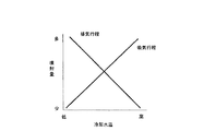
噴射パルス幅演算部11は、ECU1で取得されたエンジンの回転数、ブースト(過給圧)、吸気温度、空気量、エンジンを冷却する冷却水の冷却水温等のエンジンの運転状態を表す情報を入力し、インジェクタ2から噴射される燃料の噴射パルス幅(噴射量)を演算する。噴射パルス幅演算部11は、予め用意された図2に示すようなマップに基づいて排気行程ならびに吸気行程における燃料噴射量をそれぞれ独立して設定する。すなわち、噴射パルス幅演算部11は、冷却水温とその水温に対して気化可能な最適な噴射量との関係を示す図2のマップを参照して、機関の冷却水温に基づいて、排気行程における燃料噴射量を設定し、さらにこれとは独立して、冷却水温に基づいて吸気行程における燃料噴射量を設定する。図2に示すように、冷却水温が低くなるにつれて排気行程における燃料噴射量は多く設定する一方、吸気行程における燃料噴射量は少なく設定し、冷却水温が高くなるにつれて排気行程における燃料噴射量は少なく設定する一方、吸気行程における燃料噴射量は多く設定する。このようにして設定された燃料噴射量はインジェクタ駆動回路14に与えられる。
The injection pulse
噴射回数演算部12は、予め用意された図3に示すようなマップに基づいて、燃料の噴射回数を設定する。すなわち、噴射回数演算部12は、冷却水温とその水温に対して最適な噴射回数との関係を示す図3のマップを参照して、冷却水温に基づいて吸気行程ならびに排気行程の燃料の噴射回数を設定する。噴射回数は、図3に示すように、例えば60℃程度の閾値温度を境に、冷却水温がこの閾値温度よりも高い場合には、気化が促進されやすいので噴射回数を1回に設定する一方、低い場合には2回以上に分割して気化の促進を図る。噴射回数が1回に設定された場合には、吸気行程のみで燃料噴射を行い、噴射回数が2回以上に分割された場合には、吸気行程で燃料噴射を1回行い、排気行程で残りの回数、例えば1〜2回程度燃料の噴射を行う。冷却水温が閾値温度よりも低い場合の燃料噴射の噴射回数(3回以上)は、予め設定しておいてもよく、あるいは冷却水温に回数の閾値温度を設け、この閾値温度を境に噴射回数を増減させるようにしてもよい。このようにして設定された燃料の噴射回数はインジェクタ駆動回路14に与えられる。
The injection
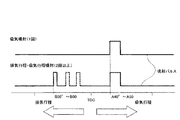
噴射タイミング演算部13は、吸気行程ならびに排気行程における燃料の噴射時期(噴射タイミング)を設定する。吸気行程における噴射タイミングは、図4に示すように、上死点(TDC)からA(アフター)40°〜50°程度の範囲内で固定して設定する。これに対して、排気行程における1又は複数の噴射タイミングは、図4に示すように、上死点(TDC)からB(ビフォー)50°〜60°程度の範囲内で固定して設定する。
The injection
なお、排気行程において、2回以上の噴射回数が設定された場合には、噴射タイミングは上記範囲内で例えば等間隔のタイミングで設定され、噴射量はそれぞれの噴射タイミングで等量に設定される。図4では、排気行程において例えば3回の噴射が実施される場合には、1回目の噴射タイミングが実線で示され、2回目以降の噴射タイミングが破線で示されている。このように設定された燃料の噴射タイミングは、インジェクタ駆動回路14に与えられる。
In the exhaust stroke, when two or more injections are set, the injection timing is set, for example, at equal intervals within the above range, and the injection amount is set to be equal at each injection timing. . In FIG. 4, when, for example, three injections are performed in the exhaust stroke, the first injection timing is indicated by a solid line, and the second and subsequent injection timings are indicated by a broken line. The fuel injection timing set in this way is given to the
インジェクタ駆動回路14は、噴射パルス幅演算部11で演算された燃料噴射量、噴射回数演算部12で演算された燃料の噴射回数、ならびに噴射タイミング演算部13で演算された燃料の噴射タイミングを入力し、入力した内容に基づいて、インジェクタ2を駆動制御する。
The
次に、図5の動作フローチャートを参照して、この実施例1の動作を説明する。 Next, the operation of the first embodiment will be described with reference to the operation flowchart of FIG.
先ず、ECU1はイグニッション(IGN)スイッチがオンされたか否かを判別し(ステップS501)、イグニッションスイッチがオンされると、ECU1で取得された冷却水温と図3に示す閾値温度とを比較し、比較結果に基づいて図3の関係を参照して燃料の噴射回数を設定する(ステップS502)。設定した燃料の噴射回数を判別し(ステップS503)、噴射回数が1回に設定された場合には、吸気行程のみで燃料噴射が実施されるので、図4に示すように予め固定された吸気行程における燃料の噴射タイミングが設定され(ステップS504)、吸気行程における燃料の噴射量が冷却水温に基づいて図2に示す関係を参照して設定される(ステップS505)。
First, the
このようにして、吸気行程における燃料の噴射回数、噴射タイミングならびに噴射量が設定された後、スタートSWがオンされたか否かを判別し(ステップS506)、スタートSWがオンされると、燃料の噴射回数、噴射タイミングならびに噴射量の信号が与えられたインジェクタ駆動回路14によってインジェクタ2が駆動制御される。これにより、噴射パルス幅演算部11で求められた燃料噴射量、噴射回数演算部12で求められた噴射回数、ならびに噴射タイミング演算部13で求められた噴射タイミングで燃料がインジェクタ2から吸気ポートに噴射され、エンジンが始動される(ステップS507)。
Thus, after the number of fuel injections, the injection timing, and the injection amount in the intake stroke are set, it is determined whether or not the start SW is turned on (step S506). The
一方、噴射回数の判別結果において、噴射回数は2回以上に設定された場合には、吸気行程と排気行程のそれぞれの行程において噴射が実施されるので、図4に示すように予め固定された排気行程における噴射タイミングが設定され(ステップS508)、続いて排気行程における燃料の噴射量が冷却水温に基づいて図2に示す関係を参照して設定される(ステップS509)。 On the other hand, in the determination result of the number of injections, when the number of injections is set to 2 or more, since the injection is performed in each of the intake stroke and the exhaust stroke, it is fixed in advance as shown in FIG. The injection timing in the exhaust stroke is set (step S508), and then the fuel injection amount in the exhaust stroke is set with reference to the relationship shown in FIG. 2 based on the coolant temperature (step S509).
次に、上述した排気行程における燃料噴射量の設定とは独立して、図4に示すように予め固定された吸気行程における燃料の噴射タイミングが設定され(ステップS510)、吸気行程における燃料の噴射量が冷却水温に基づいて図2に示す関係を参照して設定される(ステップS511)。なお、排気行程における噴射タイミングならびに噴射量の設定と、吸気行程における噴射タイミングならびに噴射量の設定の順序は吸気行程を先に設定しても構わず、順序はどちらが先であっても構わない。 Next, independently of the setting of the fuel injection amount in the exhaust stroke, the fuel injection timing in the intake stroke fixed in advance is set as shown in FIG. 4 (step S510), and the fuel injection in the intake stroke is set. The amount is set with reference to the relationship shown in FIG. 2 based on the cooling water temperature (step S511). Note that the order of setting the injection timing and injection amount in the exhaust stroke and the setting of the injection timing and injection amount in the intake stroke may be set first in the intake stroke, and whichever comes first.
このように、吸気行程ならびに排気行程における燃料の噴射回数、噴射タイミングならびに噴射量が設定された後、スタートSWがオンされたか否かを判別し(ステップS506)、スタートSWがオンされると、燃料の噴射回数、噴射タイミングならびに噴射量の信号が与えられたインジェクタ駆動回路14によってインジェクタ2が駆動制御される。これにより、噴射パルス幅演算部11で求められた燃料噴射量、噴射回数演算部12で求められた噴射回数、ならびに噴射タイミング演算部13で求められた噴射タイミングで燃料がインジェクタ2から吸気ポートに噴射され、エンジンが始動される(ステップS507)。
As described above, after the number of fuel injections, the injection timing, and the injection amount in the intake stroke and the exhaust stroke are set, it is determined whether or not the start SW is turned on (step S506). When the start SW is turned on, The
以上説明したように、上記実施例1においては、吸気行程における燃料噴射量と排気行程における燃料噴射量とを、冷却水温に基づいてそれぞれ独立して設定するようにしているので、一方の行程で設定される燃料噴射量が他方の行程で設定された燃料噴射量に依存することは回避されるので、各行程において独立して燃料噴射量を設定することができる。これにより、各行程における燃料噴射量を冷却水温に応じて最適に設定することが可能となる。この結果、各行程において噴射された燃料を十分に気化することが可能となり、不十分な気化による燃料の壁流量が各行程ともに低減され、燃焼性、ならびにエミッション特性を向上することができる。 As described above, in the first embodiment, the fuel injection amount in the intake stroke and the fuel injection amount in the exhaust stroke are set independently based on the cooling water temperature. Since it is avoided that the set fuel injection amount depends on the fuel injection amount set in the other stroke, the fuel injection amount can be set independently in each stroke. This makes it possible to optimally set the fuel injection amount in each stroke according to the coolant temperature. As a result, the fuel injected in each stroke can be sufficiently vaporized, the wall flow of the fuel due to insufficient vaporization is reduced in each stroke, and the combustibility and emission characteristics can be improved.
また、冷却水温が低くなるにつれて吸気行程における燃料噴射量を少なくする一方、燃料が噴射された後燃料が気化されるまでの時間が吸気行程に比べて長い排気行程における燃料噴射量を多くすることで、燃料の気化が悪化する低温時であっても、吸気行程ならびに排気行程の全体に亘って燃料の気化が促進され、燃料性、エミッション特性が向上するとともに、始動性が良好となる。 Further, the fuel injection amount in the intake stroke is decreased as the cooling water temperature is lowered, while the fuel injection amount in the exhaust stroke in which the time until the fuel is vaporized after the fuel is injected is longer than the intake stroke. Thus, even at a low temperature when the fuel vaporization deteriorates, the vaporization of the fuel is promoted throughout the intake stroke and the exhaust stroke, and the fuel performance and emission characteristics are improved and the startability is improved.
さらに、冷却水温が所定の閾値温度以下になった場合には、吸気行程ならびに排気行程の双方の行程において燃料を噴射することで、吸気ポート内の温度が低い場合であっても、燃料を十分に気化させることが可能となる。また、冷却水温が閾値温度以上であって、冷却水温が比較的高い場合には、燃料の気化が十分に行われる状態であるので、吸気行程のみで燃料を噴射しても燃料を十分に気化させることが可能となる。これにより、排気行程において燃料噴射を行わずに済み、燃料の節約、燃料の壁流量を低減することができる。 Furthermore, when the cooling water temperature falls below a predetermined threshold temperature, fuel is injected in both the intake stroke and the exhaust stroke so that the fuel can be sufficiently supplied even when the temperature in the intake port is low. It is possible to vaporize. In addition, when the cooling water temperature is equal to or higher than the threshold temperature and the cooling water temperature is relatively high, the fuel is sufficiently vaporized. Therefore, even if the fuel is injected only in the intake stroke, the fuel is sufficiently vaporized. It becomes possible to make it. Thereby, it is not necessary to perform fuel injection in the exhaust stroke, and fuel can be saved and the wall flow rate of the fuel can be reduced.
1…ECU
2…インジェクタ
11…噴射パルス幅演算部
12…噴射回数演算部
13…噴射タイミング演算部
14…インジェクタ駆動回路
1 ... ECU
DESCRIPTION OF
Claims (3)
前記内燃機関を冷却する冷却水の冷却水温に基づいて、吸気行程における燃料噴射量を設定する吸気行程噴射量設定手段と、
前記内燃機関を冷却する冷却水の冷却水温に基づいて、前記吸気行程噴射量設定手段による吸気行程における燃料噴射量の設定とは独立して、排気行程における燃料噴射量を設定する排気行程噴射量設定手段と、
前記吸気行程噴射量設定手段で設定された吸気行程における燃料噴射量の燃料、ならびに前記排気行程噴射量設定手段で設定された排気行程における燃料噴射量の燃料を、各行程で前記インジェクタを駆動制御して噴射制御する噴射制御手段と
を有することを特徴とする燃料噴射制御装置。 An injector for injecting fuel into the intake port of each cylinder of the internal combustion engine is provided, and when the number of times of fuel injection by the injector is plural, it is divided into both the intake stroke and the exhaust stroke of the internal combustion engine. In a fuel injection control device for an internal combustion engine for injecting fuel,
An intake stroke injection amount setting means for setting a fuel injection amount in the intake stroke based on a cooling water temperature of cooling water for cooling the internal combustion engine;
An exhaust stroke injection amount for setting the fuel injection amount in the exhaust stroke independently of the setting of the fuel injection amount in the intake stroke by the intake stroke injection amount setting means based on the cooling water temperature of the cooling water for cooling the internal combustion engine Setting means;
The injector is driven and controlled in each stroke of the fuel of the fuel injection amount in the intake stroke set by the intake stroke injection amount setting means and the fuel of the fuel injection amount in the exhaust stroke set by the exhaust stroke injection amount setting means. And a fuel injection control device for controlling the fuel injection.
ことを特徴とする請求項1記載の燃料噴射制御装置。 The intake stroke injection amount setting means sets the fuel injection amount so that the injection amount decreases as the cooling water temperature decreases, and the exhaust stroke injection amount setting means increases the injection amount as the cooling water temperature decreases. 2. The fuel injection control device according to claim 1, wherein the fuel injection amount is set so as to satisfy.
ことを特徴とする請求項1又は2に記載の燃料噴射制御装置。 3. The fuel injection control device according to claim 1, wherein when the cooling water temperature is equal to or lower than a predetermined temperature, fuel is injected separately in both an intake stroke and an exhaust stroke. 4.
Priority Applications (1)
| Application Number | Priority Date | Filing Date | Title |
|---|---|---|---|
| JP2004109083A JP2005291133A (en) | 2004-04-01 | 2004-04-01 | Fuel injection control device |
Applications Claiming Priority (1)
| Application Number | Priority Date | Filing Date | Title |
|---|---|---|---|
| JP2004109083A JP2005291133A (en) | 2004-04-01 | 2004-04-01 | Fuel injection control device |
Publications (1)
| Publication Number | Publication Date |
|---|---|
| JP2005291133A true JP2005291133A (en) | 2005-10-20 |
Family
ID=35324340
Family Applications (1)
| Application Number | Title | Priority Date | Filing Date |
|---|---|---|---|
| JP2004109083A Pending JP2005291133A (en) | 2004-04-01 | 2004-04-01 | Fuel injection control device |
Country Status (1)
| Country | Link |
|---|---|
| JP (1) | JP2005291133A (en) |
Cited By (6)
| Publication number | Priority date | Publication date | Assignee | Title |
|---|---|---|---|---|
| JP2013241924A (en) * | 2012-05-23 | 2013-12-05 | Suzuki Motor Corp | Fuel injection controller of internal combustion engine |
| WO2019049676A1 (en) | 2017-09-05 | 2019-03-14 | トヨタ自動車株式会社 | Control device and control method for internal combustion engine |
| JP2020002790A (en) * | 2018-06-25 | 2020-01-09 | トヨタ自動車株式会社 | Internal combustion engine control device |
| US10961964B2 (en) | 2017-09-05 | 2021-03-30 | Toyota Jidosha Kabushiki Kaisha | Internal combustion engine control device and control method |
| US11002213B2 (en) | 2017-09-05 | 2021-05-11 | Toyota Jidosha Kabushiki Kaisha | Internal combustion engine control device and control method |
| US11028798B2 (en) | 2017-09-05 | 2021-06-08 | Toyota Jidosha Kabushiki Kaisha | Internal-combustion-engine control device and control method |
-
2004
- 2004-04-01 JP JP2004109083A patent/JP2005291133A/en active Pending
Cited By (7)
| Publication number | Priority date | Publication date | Assignee | Title |
|---|---|---|---|---|
| JP2013241924A (en) * | 2012-05-23 | 2013-12-05 | Suzuki Motor Corp | Fuel injection controller of internal combustion engine |
| WO2019049676A1 (en) | 2017-09-05 | 2019-03-14 | トヨタ自動車株式会社 | Control device and control method for internal combustion engine |
| US10961964B2 (en) | 2017-09-05 | 2021-03-30 | Toyota Jidosha Kabushiki Kaisha | Internal combustion engine control device and control method |
| US11002213B2 (en) | 2017-09-05 | 2021-05-11 | Toyota Jidosha Kabushiki Kaisha | Internal combustion engine control device and control method |
| US11028798B2 (en) | 2017-09-05 | 2021-06-08 | Toyota Jidosha Kabushiki Kaisha | Internal-combustion-engine control device and control method |
| JP2020002790A (en) * | 2018-06-25 | 2020-01-09 | トヨタ自動車株式会社 | Internal combustion engine control device |
| JP7332276B2 (en) | 2018-06-25 | 2023-08-23 | トヨタ自動車株式会社 | Control device for internal combustion engine |
Similar Documents
| Publication | Publication Date | Title |
|---|---|---|
| US7747379B2 (en) | Control device of direct injection internal combustion engine | |
| EP2339158B1 (en) | Control apparatus for direct injection type internal combustion engine | |
| JP2006138252A (en) | Control device for internal combustion engine | |
| JP4466337B2 (en) | Control device for internal combustion engine | |
| JP2013015022A (en) | Control device of direct injection engine | |
| US20190226421A1 (en) | Engine system and method for suppressing knock | |
| JPH10339202A (en) | Cylinder-injection type fuel control device | |
| JP2012255366A (en) | Control device and control method for internal combustion engine | |
| JP2014020211A (en) | Fuel injection control device of direct-injection gasoline engine | |
| JP5321844B2 (en) | Fuel injection control device for internal combustion engine | |
| JP2005291133A (en) | Fuel injection control device | |
| JP4998632B1 (en) | Combustion control device | |
| JP2006291971A (en) | Fuel injection control device of cylinder injection type internal combustion engine | |
| JP4422677B2 (en) | In-cylinder injection internal combustion engine and fuel injection method | |
| JP2006177179A (en) | In-cylinder direct injection spark ignition internal combustion engine controller | |
| JP2008274789A (en) | Direct injection engine control system | |
| JP2007032326A (en) | Control device for internal combustion engine | |
| JP5831160B2 (en) | Control device for internal combustion engine | |
| JP2011236802A (en) | Internal combustion engine control apparatus | |
| JP2010255508A (en) | Fuel injection control device for spark ignition internal combustion engine | |
| JP3962920B2 (en) | Fuel injection control device for in-cylinder internal combustion engine | |
| JP4304463B2 (en) | Fuel injection control device for internal combustion engine | |
| JPH11270387A (en) | Starting control device of internal combustion engine | |
| JP4702214B2 (en) | Start control device for in-cylinder internal combustion engine | |
| JP2008298028A (en) | Fuel injection control device of in cylinder injection type internal combustion engine |