JP3962920B2 - Fuel injection control device for in-cylinder internal combustion engine - Google Patents
Fuel injection control device for in-cylinder internal combustion engine Download PDFInfo
- Publication number
- JP3962920B2 JP3962920B2 JP2003034581A JP2003034581A JP3962920B2 JP 3962920 B2 JP3962920 B2 JP 3962920B2 JP 2003034581 A JP2003034581 A JP 2003034581A JP 2003034581 A JP2003034581 A JP 2003034581A JP 3962920 B2 JP3962920 B2 JP 3962920B2
- Authority
- JP
- Japan
- Prior art keywords
- injection
- fuel
- fuel cut
- cycle
- return
- Prior art date
- Legal status (The legal status is an assumption and is not a legal conclusion. Google has not performed a legal analysis and makes no representation as to the accuracy of the status listed.)
- Expired - Fee Related
Links
Images


Classifications
-
- Y—GENERAL TAGGING OF NEW TECHNOLOGICAL DEVELOPMENTS; GENERAL TAGGING OF CROSS-SECTIONAL TECHNOLOGIES SPANNING OVER SEVERAL SECTIONS OF THE IPC; TECHNICAL SUBJECTS COVERED BY FORMER USPC CROSS-REFERENCE ART COLLECTIONS [XRACs] AND DIGESTS
- Y02—TECHNOLOGIES OR APPLICATIONS FOR MITIGATION OR ADAPTATION AGAINST CLIMATE CHANGE
- Y02T—CLIMATE CHANGE MITIGATION TECHNOLOGIES RELATED TO TRANSPORTATION
- Y02T10/00—Road transport of goods or passengers
- Y02T10/10—Internal combustion engine [ICE] based vehicles
- Y02T10/40—Engine management systems
Description
【0001】
【発明の属する技術分野】
本発明は、燃料を筒内に直接噴射する筒内噴射式内燃機関における燃料カットの実行方法を改善した筒内噴射式内燃機関の燃料噴射制御装置に関するものである。
【0002】
【従来の技術】
近年、低燃費、低排気エミッション、高出力の特長を兼ね備えた筒内噴射式エンジン(直噴エンジン)の需要が急増している。この筒内噴射式エンジンは、エンジン運転状態に応じて成層燃焼モードと均質燃焼モードとを切り換え、成層燃焼モードでは、少量の燃料を圧縮行程で筒内に直接噴射して点火プラグの近傍に成層混合気を形成して成層燃焼させ、均質燃焼モードでは、燃料噴射量を増量して吸気行程で筒内に燃料を直接噴射して均質混合気を形成して均質燃焼させるようにしている。
【0003】
この筒内噴射式エンジンの燃料噴射制御は、1サイクル(720℃A)中に吸気又は圧縮のいずれか一方の行程で燃料噴射を1回のみ行うものが多いが、1サイクル中に複数回の噴射を行うようにしたものがある。例えば、特許文献1(特開2001−248482号公報)等に示すように、1サイクル中に、燃料を吸気行程と圧縮行程に分割して筒内に噴射する“吸気+圧縮行程噴射”を行ったり、或は、吸気行程中に燃料を複数回に分割して筒内に噴射する“吸気行程分割噴射”を行うことによって、噴射燃料の霧化を向上させたり、ノック限界出力領域を拡大するようにしたものがある。
【0004】
また、特許文献2(特開2002−13431号公報)等に示すように、触媒早期暖機や触媒硫黄被毒回復等を行うために、吸気行程又は圧縮行程で燃料を噴射した後に膨張行程又は排気行程で少量の燃料を噴射することで、排気管内で後燃えを生じさせて排気温度を上昇させたり、排出ガス中の未燃HC濃度を増加させて触媒内部で発生する未燃HCの酸化反応の反応熱を増加させるようにしたものもある。
【0005】
【特許文献1】
特開2001−248482号公報(第2頁〜第3頁等)
【特許文献2】
特開2002−13431号公報(第2頁〜第3頁等)
【0006】
【発明が解決しようとする課題】
ところで、筒内噴射式エンジンにおいても、吸気ポート噴射式エンジンと同様に、減速時に燃費向上、減速性能向上等の目的から燃料カットを実行するようにしている。一般に、燃料カットの開始/復帰タイミングは、エンジン回転速度やアクセル開度(スロットル開度)等によって決定されるため、1サイクル中に複数回の噴射を行う噴射パターンで運転している場合には、燃料カットの開始/復帰タイミングが複数回噴射の途中(1サイクル中の2回目以降の噴射時期)になることがある。
【0007】
例えば、吸気+圧縮行程噴射や吸気行程分割噴射で運転しているときに、1サイクル中の2回目以降の燃料噴射タイミングから燃料カットの開始/復帰を実行すると、そのサイクルでの噴射量が1サイクル分の要求噴射量よりも少なくなって、要求空燃比や要求トルクを満足することができず、ドライバビリティや排気エミッションが悪くなるという問題があった。また、吸気行程又は圧縮行程で燃料を噴射した後に膨張行程又は排気行程で燃料を後噴射する場合は、膨張行程又は排気行程の燃料噴射タイミングから燃料カット復帰を実行すると、燃料カット中に温度低下した排気管内に未燃HCが排出されることになるため、未燃HCの後燃えや触媒内での未燃HCの酸化反応を促進することができず、未燃HCの排出量が増加して排気エミッションが悪くなるという問題があった。
【0008】
本発明はこのような事情を考慮してなされたものであり、従ってその目的は、1サイクル中に燃料を複数回噴射する噴射パターンで運転しているときの燃料カット開始/復帰タイミングを適正化して、燃料カットによるドライバビリティ悪化や排気エミッション悪化の問題を解決することができる筒内噴射式内燃機関の燃料噴射制御装置を提供することにある。
【0009】
【課題を解決するための手段】
上記目的を達成するために、本発明の請求項1の筒内噴射式内燃機関の燃料噴射制御装置は、燃料を噴射する行程及び/又は1サイクル中の噴射回数が異なる複数の噴射パターンの中から内燃機関の運転状態に応じた噴射パターンを設定する噴射パターン設定手段を備えたものにおいて、燃料カットを開始するタイミングを前記噴射パターン設定手段により設定された噴射パターンに応じて変化させるようにしたものである。つまり、請求項1に係る発明は、燃料カット要求の発生タイミングがその時点の噴射パターンにおける適切な燃料カット開始タイミングでなければ、適切な燃料カット開始タイミングになるまで待って燃料カットを開始する。これにより、運転中に燃料カット要求がどの様なタイミングで発生しても、常に実際の燃料カット開始タイミングをその時点の噴射パターンに応じた適切な燃料カット開始タイミングに設定することができ、燃料カット開始タイミングの悪さから引き起こされるドライバビリティ悪化や排気エミッション悪化の問題を解決することができる。
【0010】
更に、請求項1,2のように、燃料カット状態から燃料噴射を再開するタイミングを、噴射パターン設定手段により設定された噴射パターンに応じて変化させるようにすると良い。つまり、請求項1,2に係る発明は、燃料カット復帰要求の発生タイミングがその時点の噴射パターンにおける適切な燃料カット復帰タイミングでなければ、適切な燃料カット復帰タイミングになるまで待って燃料カット状態から復帰する。これにより、運転中に燃料カット復帰要求がどの様なタイミングで発生しても、常に実際の燃料カット復帰タイミングをその時点の噴射パターンに応じた適切な燃料カット復帰タイミングに設定することができ、燃料カット復帰タイミングの悪さから引き起こされるドライバビリティ悪化や排気エミッション悪化の問題を解決することができる。
【0011】
具体的には、請求項3のように、1サイクル中の噴射回数が2回以上の噴射パターンに設定されているときは、1サイクル中の2回目以降の燃料噴射タイミングから燃料カットを開始することを禁止し、1回目の燃料噴射タイミングからのみ燃料カットを許可するようにすると良い。同様に、請求項4のように、1サイクル中の2回目以降の燃料噴射タイミングから燃料カットを復帰することを禁止し、1回目の燃料噴射タイミングからのみ燃料カット復帰を許可するようにすると良い。
【0012】
上記請求項3,4のように構成すれば、運転中に燃料カット要求や燃料カット復帰要求がどの様なタイミングで発生しても、常に実際の燃料カット開始タイミングや燃料カット復帰タイミングを最適なタイミングである1回目の燃料噴射タイミングに設定することができる。
【0013】
また、請求項5のように、1サイクル中の噴射回数が2回以上の噴射パターンに設定されているときは、1サイクル中の2回目以降の燃料噴射タイミングから燃料カット復帰要求が発生した場合に、当該サイクル内の燃料カットされた噴射回数分の噴射量を当該サイクル内の残りの噴射量に加算して燃料噴射を再開するようにしても良い。このようにすれば、1サイクル中の2回目以降の燃料噴射タイミングからの燃料カット復帰を実現して、燃料カット復帰の応答性を高めながら、燃料カット復帰時のサイクルの実噴射量を1サイクル分の要求噴射量に一致させることができ、サイクル途中からの燃料カット復帰によるドライバビリティ悪化や排気エミッション悪化の問題を解決することができる。
【0014】
この場合、請求項6のように、1サイクル中の2回目以降の燃料噴射タイミングから燃料カット復帰要求が発生した場合に、当該サイクル内の燃料カットされた噴射回数分の噴射量をそれ以降の噴射量に加算した合計噴射量が所定値以上であれば、当該サイクル途中からの燃料カット復帰を禁止するようにすると良い。つまり、2回目以降の噴射動作で噴射可能な燃料量には限界があり、また、2回目以降の噴射量が多くなり過ぎると、噴射燃料の霧化状態が悪くなって燃焼状態が悪化する懸念があるため、燃料カットされた噴射回数分の噴射量をそれ以降の噴射量に加算した合計噴射量が多くなり過ぎるような場合は、当該サイクル途中からの燃料カット復帰を禁止し、次のサイクルまで燃料カット復帰を待つことで、燃焼状態悪化や排気エミッション悪化の問題を解決することができる。
【0015】
【発明の実施の形態】
[実施形態(1)]
以下、本発明の実施形態(1)を図1乃至図7に基づいて説明する。まず、図1に基づいてエンジン制御システム全体の概略構成を説明する。筒内噴射式の内燃機関である筒内噴射式エンジン11の吸気管12の最上流部には、エアクリーナ13が設けられ、このエアクリーナ13の下流側に、吸入空気量を検出するエアフローメータ14が設けられている。このエアフローメータ14の下流側には、DCモータ等のモータ15によって駆動されるスロットルバルブ16が設けられ、このスロットルバルブ16の開度(スロットル開度)がスロットル開度センサ17によって検出される。
【0016】
また、スロットルバルブ16の下流側には、サージタンク18が設けられ、このサージタンク18に、吸気管圧力を検出する吸気管圧力センサ19が設けられている。また、サージタンク18には、エンジン11の各気筒に空気を導入する吸気マニホールド20が設けられ、各気筒の吸気マニホールド20に、筒内の気流強度(スワール流強度やタンブル流強度)を制御する気流制御弁31が設けられている。
【0017】
エンジン11の各気筒の上部には、それぞれ燃料を筒内に直接噴射する燃料噴射弁21が取り付けられている。エンジン11のシリンダヘッドには、各気筒毎に点火プラグ22が取り付けられ、各点火プラグ22の火花放電によって筒内の混合気に着火される。また、エンジン11の吸気バルブ37と排気バルブ38には、それぞれバルブタイミングを可変する可変バルブタイミング機構39,40が設けられている。
【0018】
エンジン11のシリンダブロックには、ノッキングを検出するノックセンサ32と、冷却水温を検出する冷却水温センサ23とが取り付けられている。また、クランク軸(図示せず)の外周側には、所定のクランク角毎にクランク角信号を出力するクランク角センサ24が取り付けられている。このクランク角センサ24の出力信号に基づいてクランク角やエンジン回転速度が検出される。
【0019】
一方、エンジン11の排気管25には、排出ガスを浄化する上流側触媒26と下流側触媒27が設けられ、上流側触媒26の上流側に、排出ガスの空燃比又はリッチ/リーン等を検出する排出ガスセンサ28(空燃比センサ、酸素センサ等)が設けられている。本実施形態では、上流側触媒26として理論空燃比付近で排出ガス中のCO,HC,NOx等を浄化する三元触媒が設けられ、下流側触媒27としてNOx吸蔵還元型触媒が設けられている。このNOx吸蔵還元型触媒27は、排出ガスの空燃比がリーンのときに排出ガス中のNOxを吸蔵し、空燃比が理論空燃比付近又はリッチになったときに吸蔵NOxを還元浄化して放出する特性を持っている。
【0020】
また、排気管25のうちの上流側触媒26の下流側と吸気管12のうちのスロットルバルブ16の下流側のサージタンク18との間に、排出ガスの一部を吸気側に還流させるためのEGR配管33が接続され、このEGR配管33の途中に排出ガス還流量(EGR量)を制御するEGR弁34が設けられている。また、アクセルペダル35の踏込量(アクセル開度)がアクセルセンサ36によって検出される。
【0021】
前述した各種センサの出力は、エンジン制御回路(以下「ECU」と表記する)30に入力される。このECU30は、マイクロコンピュータを主体として構成され、内蔵されたROM(記憶媒体)に記憶された各種の制御ルーチンを実行することで、エンジン運転状態に応じて燃料噴射弁21の燃料噴射量や燃料噴射時期、点火プラグ22の点火時期等を制御する。
【0022】
本実施形態(1)では、ECU30は、図2に示すように、燃料を噴射する行程と1サイクル中の噴射回数が異なる例えば8種類の噴射パターン▲1▼〜▲8▼の中から、エンジン運転状態に応じていずれか1つの噴射パターンを設定するようにしている(この機能が特許請求の範囲でいう噴射パターン設定手段に相当する)。
【0023】
ここで、噴射パターン▲1▼は、吸気行程で1回のみ噴射する通常の吸気行程噴射であり、噴射パターン▲2▼は、圧縮行程で1回のみ噴射する通常の圧縮行程噴射である。噴射パターン▲3▼は、1サイクル中に燃料を吸気行程と圧縮行程に分割してそれぞれ少なくとも1回ずつ噴射する吸気+圧縮行程噴射であり、噴射パターン▲4▼は、吸気行程中に燃料を複数回に分割して噴射する吸気行程分割噴射である。
【0024】
一方、噴射パターン▲5▼は、圧縮行程で燃料を1回噴射して成層燃焼させた後、膨張行程で少量の燃料を噴射して排気温度を上昇させる圧縮+膨張行程噴射であり、噴射パターン▲6▼は、吸気行程で燃料を1回噴射して均質燃焼させた後、膨張行程で少量の燃料を噴射して排気温度を上昇させる吸気+膨張行程噴射である。これら2つの噴射パターン▲5▼,▲6▼は、触媒早期暖機制御等に用いられる。
【0025】
噴射パターン▲7▼は、吸気行程で燃料を1回噴射して均質燃焼させた後、排気行程で少量の燃料を噴射する吸気+排気行程噴射噴射であり、噴射パターン▲8▼は、圧縮行程で燃料を1回噴射して成層燃焼させた後、排気行程で少量の燃料を噴射する圧縮+排気行程噴射噴射である。これら2つの噴射パターン▲7▼,▲8▼は、いずれも、排気行程で少量の燃料を噴射することで、排出ガス中の未燃HC濃度を増加させて触媒27内部で未燃HCの酸化反応を発生させ、その反応熱で触媒27の硫黄被毒を回復させる。
【0026】
更に、ECU30は、エンジン運転中に燃料カット要求が発生したとき(燃料カットフラグがOFFからONに切り換えられたとき)、燃料カットを実行すると共に、燃料カット復帰要求が発生したとき(燃料カットフラグがONからOFFに切り換えられたとき)、燃料噴射を再開する。
【0027】
本実施形態(1)では、ECU30は、図3乃至図7に示すように、燃料カット要求が発生したときに、燃料カット開始タイミングをその時点の噴射パターンに応じて変化させ、その後、燃料カット復帰要求が発生したときに、燃料カット復帰タイミングをその時点の噴射パターンに応じて変化させる。
【0028】
以下、本実施形態(1)の燃料カット開始/復帰タイミングの制御例を図3乃至図7を用いて説明する。
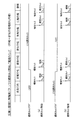
図3は、吸気+圧縮行程噴射パターン(図2の▲3▼)で運転しているときの燃料カット開始/復帰タイミングの制御例を示している。図3(a)に示すように、燃料カットフラグがOFFからONに切り換えられて燃料カット要求が発生した時点で、既に吸気行程の噴射が実行されていれば、圧縮行程の噴射セットタイミング前であっても、圧縮行程の噴射をカットせずに実行する。そして、次のサイクルの最初(1回目)の噴射である吸気行程の噴射セット時に、燃料カットを許可して燃料カットを開始する。一方、燃料カット要求が吸気行程の噴射セット前に発生すれば、その吸気行程の噴射セット時に、直ちに燃料カットを許可して燃料カットを開始する。
【0029】
その後、図3(b)に示すように、燃料カットフラグがONからOFFに切り換えられて燃料カット復帰要求が発生した時点で、既に吸気行程の噴射セットタイミングを過ぎていれば、圧縮行程の噴射セットタイミング前であっても、圧縮行程の噴射セット(燃料カット復帰)を行わず、燃料カットを継続する。そして、次のサイクルの最初(1回目)の噴射である吸気行程の噴射セット時に、燃料カット復帰を許可して燃料噴射を再開する。一方、燃料カット復帰要求が吸気行程の噴射セット前に発生すれば、その吸気行程の噴射セット時に、直ちに燃料カット復帰を許可して燃料噴射を再開する。
【0030】
図4は、吸気+膨張行程噴射パターン(図2の▲6▼)で運転しているときの燃料カット開始/復帰タイミングの制御例を示している。図4(a)に示すように、燃料カットフラグがOFFからONに切り換えられて燃料カット要求が発生した時点で、既に吸気行程の噴射が実行されていれば、膨張行程の噴射セットタイミング前であっても、膨張行程の噴射をカットせずに実行する。そして、次のサイクルの最初(1回目)の噴射である吸気行程の噴射セット時に、燃料カットを許可して燃料カットを開始する。一方、燃料カット要求が吸気行程の噴射セット前に発生すれば、その吸気行程の噴射セット時に、直ちに燃料カットを許可して燃料カットを開始する。
【0031】
その後、図4(b)に示すように、燃料カットフラグがONからOFFに切り換えられて燃料カット復帰要求が発生した時点で、既に吸気行程の噴射セットタイミングを過ぎていれば、膨張行程の噴射セットタイミング前であっても、膨張行程の噴射セット(燃料カット復帰)を行わず、燃料カットを継続する。そして、次のサイクルの最初(1回目)の噴射である吸気行程の噴射セット時に、燃料カット復帰を許可して燃料噴射を再開する。一方、燃料カット復帰要求が吸気行程の噴射セット前に発生すれば、その吸気行程の噴射セット時に、直ちに燃料カット復帰を許可して燃料噴射を再開する。
【0032】
以上説明した吸気+膨張行程噴射パターン(図2の▲6▼)の燃料カット開始/復帰タイミングの制御方法は、吸気+排気行程噴射パターン(図2の▲7▼)についても同様である。
【0033】
図5は、圧縮+膨張行程噴射パターン(図2の▲5▼)で運転しているときの燃料カット開始/復帰タイミングの制御例を示している。図5(a)に示すように、燃料カットフラグがOFFからONに切り換えられて燃料カット要求が発生した時点で、既に圧縮行程の噴射が実行されていれば、膨張行程の噴射セットタイミング前であっても、膨張行程の噴射をカットせずに実行する。そして、次のサイクルの最初(1回目)の噴射である圧縮行程の噴射セット時に、燃料カットを許可して燃料カットを開始する。一方、燃料カット要求が圧縮行程の噴射セット前に発生すれば、その圧縮行程の噴射セット時に、直ちに燃料カットを許可して燃料カットを開始する。
【0034】
その後、図5(b)に示すように、燃料カットフラグがONからOFFに切り換えられて燃料カット復帰要求が発生した時点で、既に圧縮行程の噴射セットタイミングを過ぎていれば、膨張行程の噴射セットタイミング前であっても、膨張行程の噴射セット(燃料カット復帰)を行わず、燃料カットを継続する。そして、次のサイクルの最初(1回目)の噴射である圧縮行程の噴射セット時に、燃料カット復帰を許可して燃料噴射を再開する。一方、燃料カット復帰要求が圧縮行程の噴射セット前に発生すれば、その圧縮行程の噴射セット時に、直ちに燃料カット復帰を許可して燃料噴射を再開する。
【0035】
以上説明した圧縮+膨張行程噴射パターン(図2の▲5▼)の燃料カット開始/復帰タイミングの制御方法は、圧縮+排気行程噴射パターン(図2の▲8▼)についても同様である。
【0036】
図6は、吸気行程で燃料を2回に分割して噴射する吸気行程分割噴射パターン(図2の▲4▼)で運転しているときの燃料カット開始/復帰タイミングの制御例を示している。図6(a)に示すように、燃料カットフラグがOFFからONに切り換えられて燃料カット要求が発生した時点で、既に吸気行程の1回目の噴射が実行されていれば、2回目の噴射セットタイミング前であっても、2回目の噴射をカットせずに実行する。そして、次のサイクルの吸気行程の1回目の噴射セット時に、燃料カットを許可して燃料カットを開始する。一方、燃料カット要求が吸気行程の1回目の噴射セット前に発生すれば、その1回目の噴射セット時に、直ちに燃料カットを許可して燃料カットを開始する。
【0037】
その後、図6(b)に示すように、燃料カットフラグがONからOFFに切り換えられて燃料カット復帰要求が発生した時点で、既に吸気行程の1回目の噴射セットタイミングを過ぎていれば、2回目の噴射セットタイミング前であっても、2回目の噴射セット(燃料カット復帰)を行わず、燃料カットを継続する。そして、次のサイクルの吸気行程の1回目の噴射セット時に、燃料カット復帰を許可して燃料噴射を再開する。一方、燃料カット復帰要求が吸気行程の1回目の噴射セット前に発生すれば、その1回目の噴射セット時に、直ちに燃料カット復帰を許可して燃料噴射を再開する。
【0038】
以上説明した燃料カット開始/復帰タイミングの制御は、ECU30により図7に示す燃料カット制御ルーチンに従って実行される。本ルーチンは、エンジン運転中に例えば噴射セットタイミングに同期して起動され、特許請求の範囲でいう燃料カット手段及び燃料カット復帰手段としての役割を果たす。本ルーチンが起動されると、まずステップ101で、燃料カットフラグがON(燃料カット要求有り)であるか否かを判定し、燃料カットフラグがONであれば、ステップ102に進み、既に燃料カットが開始されているか否かを判定し、既に燃料カットが開始されていれば、そのまま燃料カットを継続する(ステップ109)。
【0039】
これに対して、上記ステップ102で、まだ燃料カットが開始されていないと判定されれば、ステップ103に進み、1サイクル中の噴射回数が複数回であるか否か(噴射パターンが図2の▲3▼〜▲8▼のいずれかであるか否か)を判定し、1サイクル中の噴射回数が1回のみ(噴射パターンが図2の▲1▼又は▲2▼)であれば、ステップ109に進み、直ちに燃料カットを開始する。
【0040】
上記ステップ103で、1サイクル中の噴射回数が複数回であると判定されれば、ステップ104に進み、現在の時刻が1回目の噴射セット後であるか否かを判定し、1回目の噴射セット後であれば、ステップ105に進み、燃料カットを禁止し、2回目の噴射をカットせずに実行する。この場合は、次のサイクルで本ルーチンが最初に起動されたときに、ステップ101→102→103→104へと進み、このステップ104で、「No」と判定されて、ステップ109に進み、1回目の噴射から燃料カットが開始される。
【0041】
このように、本ルーチンでは、燃料カットフラグがOFFからONに切り換えられて燃料カット要求が発生した時点で、既に1回目の噴射が実行されていれば、2回目の噴射セットタイミング前であっても、2回目の噴射をカットせずに実行した後、次のサイクルの1回目の噴射セット時に、燃料カットを許可して燃料カットを開始する(ステップ101〜105、109)。
【0042】
一方、ステップ101で、燃料カットフラグがOFF(燃料カット要求無し)と判定されれば、ステップ106に進み、既に燃料噴射が開始されているか否か(燃料カット中でないか否か)を判定し、既に燃料噴射が開始されていれば、そのまま燃料噴射を継続する(ステップ110)。
【0043】
上記ステップ106で、まだ燃料噴射が開始されていない(燃料カット中である)と判定されれば、ステップ107に進み、1サイクル中の噴射回数が複数回であるか否か(噴射パターンが図2の▲3▼〜▲8▼のいずれかであるか否か)を判定して、1サイクル中の噴射回数が1回のみ(噴射パターンが図2の▲1▼又は▲2▼)であれば、ステップ110に進み、直ちに燃料噴射を再開する(燃料カットから復帰する)。
【0044】
一方、上記ステップ107で、1サイクル中の噴射回数が複数回であると判定されれば、ステップ108に進み、現在の時刻が1回目の噴射セットタイミング後であるか否かを判定し、1回目の噴射セットタイミング後であれば、ステップ109に進み、燃料カット復帰を禁止し、燃料カットを継続する。この場合は、次のサイクルで本ルーチンが最初に起動されたときに、ステップ101→106→107→108へと進み、このステップ108で、「No」と判定されて、ステップ110に進み、1回目の噴射から燃料噴射を再開する(燃料カットから復帰する)。
【0045】
このように、本ルーチンでは、燃料カットフラグがONからOFFに切り換えられて燃料カット復帰要求が発生した時点で、既に1回目の噴射セットタイミングを過ぎていれば、2回目の噴射セットタイミング前であっても、2回目の噴射セット(燃料カット復帰)を行わず、燃料カットを継続した後、次のサイクルの1回目の噴射セット時に、燃料カット復帰を許可して燃料噴射を再開する(ステップ101、106〜110)。
【0046】
以上説明した本実施形態(1)によれば、1サイクル中の2回目の噴射セットタイミングからの燃料カット開始/復帰を禁止し、1回目の噴射セットタイミングからのみ燃料カット開始/復帰を許可するようにしたので、エンジン運転中に燃料カット要求や燃料カット復帰要求がどの様なタイミングで発生しても、常に実際の燃料カット開始タイミングや燃料カット復帰タイミングを最適なタイミングである1回目の噴射セットタイミングに設定することができて、燃料カットによるドライバビリティ悪化や排気エミッション悪化の問題を解決することができる。
【0047】
尚、本実施形態(1)では、1サイクル中の噴射回数を2回としたが、これを3回以上としても良く、また、図2の▲3▼〜▲8▼のうちの一部の噴射パターンについてのみ、本実施形態(1)の燃料カット開始/復帰制御を適用するようにしても良い。
【0048】
[実施形態(2)]
上記実施形態(1)では、1サイクル中の2回目の噴射セットタイミングからの燃料カット復帰を禁止し、1回目の噴射セットタイミングからのみ燃料カット復帰を許可するようにしたが、図8乃至図10に示す本発明の実施形態(2)では、1サイクル中の噴射回数が複数回(例えば2回)の噴射パターンに設定されているときは、1サイクル中の2回目以降の燃料噴射タイミングから燃料カット復帰要求が発生した場合に、当該サイクル内の燃料カットされた噴射回数分の噴射量を当該サイクル内の残りの噴射量に加算して燃料噴射を再開するようにしている。
【0049】
以下、本実施形態(2)の燃料カット復帰時の制御例を図8及び図9を用いて説明する。
【0050】
図8は、吸気行程分割噴射パターン(図2の▲4▼)で運転しているときの燃料カット復帰時の制御例を示している。燃料カットフラグがONからOFFに切り換えられて燃料カット復帰要求が発生した時点で、既に吸気行程の1回目の噴射セットタイミングを過ぎていても、2回目の噴射セットタイミング前であれば、カットされた1回目の噴射量を2回目の噴射量に加算して、その合計噴射量を2回目の噴射量としてセットし、2回目の噴射から燃料噴射を再開する(燃料カットから復帰する)。これにより、1サイクル中の2回目の噴射から燃料噴射を再開する場合でも、1サイクル分の要求噴射量に相当する噴射量を筒内に噴射することができる。
【0051】
図9は、吸気+圧縮行程噴射パターン(図2の▲3▼)で運転しているときの燃料カット復帰時の制御例を示している。燃料カットフラグがONからOFFに切り換えられて燃料カット復帰要求が発生した時点で、既に吸気行程の噴射セットタイミングを過ぎていても、圧縮行程の噴射セットタイミング前であれば、カットされた吸気行程の噴射量を圧縮行程の噴射量に加算して、その合計噴射量を圧縮行程の噴射量としてセットし、圧縮行程の噴射から燃料噴射を再開する(燃料カットから復帰する)。これにより、1サイクル中の2回目の噴射である圧縮行程の噴射から燃料噴射を再開する場合でも、1サイクル分の要求噴射量に相当する噴射量を筒内に噴射することができる。
【0052】
以上説明した本実施形態(2)の燃料カット復帰制御は、図10に示す燃料カット制御ルーチンに従って実行される。本ルーチンは、前記実施形態(1)の図7のステップ108以降の処理が異なるだけであり、それ以外の各ステップの処理は、前記実施形態(1)と同じである。但し、膨張行程や排気行程で後噴射する噴射パターン(図2の▲5▼〜▲8▼)については、本実施形態(2)の燃料カット復帰制御は適用されず、前記実施形態(1)の燃料カット復帰制御が適用される。
【0053】
1サイクル中の噴射回数が複数回(噴射パターンが図2の▲3▼又は▲4▼)で運転しているときに、燃料カットフラグがONからOFFに切り換えられて燃料カット復帰要求が発生すると、図10のステップ101→106→107→108へと進み、現在の時刻が1回目の噴射セットタイミング後であるか否かを判定し、1回目の噴射セットタイミング後であれば、ステップ111に進み、カットされた1回目の噴射量を2回目の噴射量に加算して、その合計噴射量を2回目の噴射量としてセットした後、ステップ110に進み、2回目の噴射から燃料噴射を再開する(燃料カットから復帰する)。
【0054】
以上説明した本実施形態(2)によれば、1サイクル中の2回目の噴射から燃料噴射を再開する場合でも、1サイクル分の要求噴射量に相当する噴射量を筒内に噴射することができて、燃料カット復帰の応答性を高めながら、燃料カット復帰時のサイクルの実噴射量を1サイクル分の要求噴射量に一致させることができ、サイクル途中からの燃料カット復帰によるドライバビリティ悪化や排気エミッション悪化の問題を解決することができる。
【0055】
尚、本実施形態(2)では、1サイクル中の噴射回数を2回としたが、1サイクル中の噴射回数が3回以上の噴射パターンに対しても、本実施形態(2)の燃料カット復帰時の制御を適用することができる。
【0056】
例えば、1サイクル中の噴射回数が3回となる噴射パターンに対して本実施形態(2)の燃料カット復帰時の制御を適用する場合は、1サイクル中の2回目の噴射から燃料噴射を再開するときは、カットされた1回目の噴射量を2回目の噴射量に加算するようにしても良いが、カットされた1回目の噴射量を2分割又は所定の比率で分割して2回目と3回目の噴射量に加算するようにしても良い。この場合、1サイクル中の2回目の噴射から燃料噴射を再開することのみを許容し、3回目の噴射から燃料噴射を再開することを禁止するようにしても良い。勿論、3回目の噴射のみで1サイクル分の要求噴射量に相当する噴射量を噴射する余裕がある場合は、3回目の噴射から燃料噴射を再開するようにしても良く、この場合は、カットされた1回目と2回目の合計噴射量を3回目の噴射量に加算すれば良い。1サイクル中の噴射回数が4回以上の噴射パターンに対しても、同様に制御すれば良い。
【0057】
[実施形態(3)]
上記実施形態(2)では、1サイクル中の2回目以降の燃料噴射タイミングから燃料カット復帰要求が発生した場合に、当該サイクル内の燃料カットされた噴射回数分の噴射量を当該サイクル内の残りの噴射量に加算して燃料噴射を再開するようにしているが、2回目以降の噴射動作で噴射可能な燃料量には限界があり、また、2回目以降の噴射量が多くなり過ぎると、噴射燃料の霧化状態が悪くなって燃焼状態が悪化する懸念がある。
【0058】
そこで、図11乃至図12に示す本発明の実施形態(3)では、1サイクル中の2回目以降の燃料噴射タイミングから燃料カット復帰要求が発生した場合に、当該サイクル内の燃料カットされた噴射回数分の噴射量をそれ以降の噴射量に加算した合計噴射量が所定値以上(最大許容噴射量以上)であれば、当該サイクル途中からの燃料カット復帰を禁止するようにしている。
【0059】
以下、本実施形態(3)の燃料カット復帰時の制御例を図11を用いて説明する。
図11は、吸気+圧縮行程噴射パターン(図2の▲3▼)で運転しているときの燃料カット復帰時の制御例を示している。燃料カットフラグがONからOFFに切り換えられて燃料カット復帰要求が発生した時点で、既に吸気行程の噴射セットタイミングを過ぎていても、圧縮行程の噴射セットタイミング前であれば、カットされた吸気行程の噴射量を圧縮行程の噴射量に加算して、その合計噴射量が所定値以下(圧縮行程の最大許容噴射量以下)であるか否かを判定する。その結果、合計噴射量が所定値以下であると判定されれば、図11(a)に示すように、合計噴射量を圧縮行程の噴射量としてセットし、圧縮行程の噴射から燃料噴射を再開する。
【0060】
これに対して、合計噴射量が所定値よりも多いと判定された場合は、圧縮行程の噴射セット(燃料カット復帰)を行わず、燃料カットを継続し、次のサイクルの1回目の噴射である吸気行程の噴射セット時に、燃料カット復帰を許可して燃料噴射を再開する。
【0061】
以上説明した本実施形態(3)の燃料カット復帰制御は、図12に示す燃料カット制御ルーチンに従って実行される。本ルーチンは、前記実施形態(2)の図10のステップ111以降の処理が異なるだけであり、それ以外の各ステップの処理は、前記実施形態(1),(2)と同じである。但し、膨張行程や排気行程で後噴射する噴射パターン(図2の▲5▼〜▲8▼)については、本実施形態(3)の燃料カット復帰制御は適用されず、前記実施形態(1)の燃料カット復帰制御が適用される。
【0062】
1サイクル中の噴射回数が複数回(噴射パターンが図2の▲3▼又は▲4▼)で運転しているときに、燃料カットフラグがONからOFFに切り換えられて燃料カット復帰要求が発生すると、図12のステップ101→106→107→108へと進み、現在の時刻が1回目の噴射セットタイミング後であるか否かを判定し、1回目の噴射セットタイミング後であれば、ステップ111に進み、カットされた1回目の噴射量を2回目の噴射量に加算して2回目の合計噴射量を求める。この後、ステップ112に進み、2回目の合計噴射量が所定値以下(最大許容噴射量以下)であるか否かを判定する。その結果、2回目の合計噴射量が所定値以下であると判定されれば、ステップ110に進み、上記ステップ111で算出した合計噴射量を2回目の噴射量としてセットし、2回目の噴射から燃料噴射を再開する。
【0063】
これに対して、上記ステップ112で、2回目の合計噴射量が所定値よりも多いと判定された場合は、2回目の噴射セット(燃料カット復帰)を行わず、ステップ109に進み、燃料カットを継続する。この場合は、次のサイクルの1回目の噴射セット時に、燃料カット復帰を許可して1回目の噴射から燃料噴射を再開する。
【0064】
以上説明した本実施形態(3)では、燃料カットされた1回目の噴射量を2回目の噴射量に加算した合計噴射量が所定値以下(最大許容噴射量以下)であれば、前記実施形態(2)と同じように、その合計噴射量を2回目の噴射量としてセットして、2回目の噴射から燃料噴射を再開するので、燃料カット復帰の応答性を高めながら、燃料カット復帰時の実噴射量を要求噴射量に一致させることができる。一方、合計噴射量が所定値(最大許容噴射量)を越えるような場合は、2回目の噴射からの燃料カット復帰を禁止し、次のサイクルまで燃料カット復帰を待つようにしたので、燃焼状態悪化や排気エミッション悪化の問題を解決することができる。
【0065】
尚、ステップ112で合計噴射量と比較する所定値(最大許容噴射量)は、予め設定した固定値としても良いが、これをエンジン運転状態に応じてマップ等により設定するようにしても良い。
【図面の簡単な説明】
【図1】本発明の実施形態(1)におけるエンジン制御システム全体の概略構成図
【図2】噴射パターンの種類を説明する図
【図3】実施形態(1)の吸気+圧縮行程噴射パターンでの燃料カット開始/復帰タイミングの制御例を示すタイムチャート
【図4】実施形態(1)の吸気+膨張行程噴射パターンでの燃料カット開始/復帰タイミングの制御例を示すタイムチャート
【図5】実施形態(1)の圧縮+膨張行程噴射パターンでの燃料カット開始/復帰タイミングの制御例を示すタイムチャート
【図6】実施形態(1)の吸気行程分割噴射パターンでの燃料カット開始/復帰タイミングの制御例を示すタイムチャート
【図7】実施形態(1)の燃料カット制御ルーチンの処理の流れを示すフローチャート
【図8】実施形態(2)の吸気行程分割噴射パターンでの燃料カット復帰時の制御例を示すタイムチャート
【図9】実施形態(2)の吸気+圧縮行程噴射パターンでの燃料カット復帰時の制御例を示すタイムチャート
【図10】実施形態(2)の燃料カット制御ルーチンの処理の流れを示すフローチャート
【図11】実施形態(3)の吸気+圧縮行程噴射パターンでの燃料カット復帰時の制御例を示すタイムチャート
【図12】実施形態(3)の燃料カット制御ルーチンの処理の流れを示すフローチャート
【符号の説明】
11…筒内噴射式エンジン(筒内噴射式内燃機関)、12…吸気管、16…スロットルバルブ、21…燃料噴射弁、22…点火プラグ、25…排気管、30…ECU(燃料カット手段,燃料カット復帰手段,噴射パターン設定手段)。[0001]
BACKGROUND OF THE INVENTION
The present invention relates to a fuel injection control device for a direct injection internal combustion engine that improves a method for performing fuel cut in a direct injection internal combustion engine that directly injects fuel into the direct injection cylinder.
[0002]
[Prior art]
In recent years, the demand for in-cylinder injection engines (direct injection engines) that have the features of low fuel consumption, low exhaust emission, and high output has been increasing rapidly. This in-cylinder injection engine switches between the stratified combustion mode and the homogeneous combustion mode according to the engine operating state. In the stratified combustion mode, a small amount of fuel is directly injected into the cylinder in the compression stroke, and stratified in the vicinity of the spark plug. In the homogeneous combustion mode, the fuel injection amount is increased and the fuel is directly injected into the cylinder in the intake stroke to form a homogeneous mixture and perform homogeneous combustion in the homogeneous combustion mode.
[0003]
In many cases, the fuel injection control of the in-cylinder injection type engine performs fuel injection only once in one stroke of intake or compression during one cycle (720 ° C. A). There is something that was made to perform injection. For example, as shown in Patent Document 1 (Japanese Patent Laid-Open No. 2001-248482) and the like, during one cycle, “intake + compression stroke injection” is performed in which fuel is divided into an intake stroke and a compression stroke and injected into a cylinder. Or, by performing "intake stroke split injection" in which fuel is divided into a plurality of times and injected into the cylinder during the intake stroke, the atomization of the injected fuel is improved or the knock limit output region is expanded. There is something like that.
[0004]
Further, as shown in Patent Document 2 (Japanese Patent Application Laid-Open No. 2002-13431) and the like, in order to perform early catalyst warm-up, catalytic sulfur poisoning recovery, and the like, an expansion stroke or an injection stroke is performed after fuel is injected in an intake stroke or a compression stroke. By injecting a small amount of fuel in the exhaust stroke, afterburning occurs in the exhaust pipe to raise the exhaust temperature, or the unburned HC concentration in the exhaust gas is increased to oxidize unburned HC generated inside the catalyst. Some have increased the heat of reaction.
[0005]
[Patent Document 1]
Japanese Patent Laid-Open No. 2001-248482 (pages 2 to 3 etc.)
[Patent Document 2]
Japanese Patent Laid-Open No. 2002-13431 (pages 2 to 3 etc.)
[0006]
[Problems to be solved by the invention]
By the way, in the cylinder injection type engine, as in the intake port injection type engine, the fuel cut is executed for the purpose of improving the fuel consumption and the deceleration performance at the time of deceleration. In general, the fuel cut start / return timing is determined by the engine speed, the accelerator opening (throttle opening), and the like, so when operating with an injection pattern in which multiple injections are performed during one cycle. The fuel cut start / return timing may be in the middle of multiple injections (second and subsequent injection timings in one cycle).
[0007]
For example, if the fuel cut start / return is executed from the second and subsequent fuel injection timings in one cycle while operating with intake + compression stroke injection or intake stroke split injection, the injection amount in that cycle is 1 There has been a problem that the required injection amount for the cycle becomes smaller, the required air-fuel ratio and the required torque cannot be satisfied, and drivability and exhaust emission are deteriorated. In addition, when fuel is injected in the expansion stroke or the exhaust stroke after the fuel is injected in the intake stroke or the compression stroke, if the fuel cut return is executed from the fuel injection timing of the expansion stroke or the exhaust stroke, the temperature decreases during the fuel cut. Since unburned HC is discharged into the exhaust pipe, the afterburning of unburned HC and the oxidation reaction of unburned HC in the catalyst cannot be promoted, and the amount of unburned HC emissions increases. As a result, exhaust emissions deteriorated.
[0008]
The present invention has been made in view of such circumstances. Therefore, the object of the present invention is to optimize the fuel cut start / return timing when operating in an injection pattern in which fuel is injected a plurality of times during one cycle. An object of the present invention is to provide a fuel injection control device for a direct injection internal combustion engine that can solve the problems of drivability deterioration and exhaust emission deterioration due to fuel cut.
[0009]
[Means for Solving the Problems]
In order to achieve the above object, a fuel injection control device for a direct injection internal combustion engine according to claim 1 of the present invention includes a plurality of injection patterns having different strokes of fuel and / or different number of injections in one cycle. Provided with an injection pattern setting means for setting an injection pattern according to the operating state of the internal combustion engine, the timing for starting the fuel cut is changed according to the injection pattern set by the injection pattern setting means. Is. That is, according to the first aspect of the present invention, if the generation timing of the fuel cut request is not an appropriate fuel cut start timing in the injection pattern at that time, the fuel cut is started after reaching an appropriate fuel cut start timing. As a result, the actual fuel cut start timing can always be set to an appropriate fuel cut start timing according to the injection pattern at that time, regardless of when the fuel cut request occurs during operation. The problem of drivability deterioration and exhaust emission deterioration caused by poor cutting start timing can be solved.
[0010]
Further claims 1 , 2 As described above, the timing at which fuel injection is restarted from the fuel cut state may be changed according to the injection pattern set by the injection pattern setting means. That is, the claim 1 , 2 In the invention according to the above, if the generation timing of the fuel cut return request is not an appropriate fuel cut return timing in the injection pattern at that time, the fuel cut state is returned after waiting until an appropriate fuel cut return timing. As a result, the actual fuel cut return timing can always be set to an appropriate fuel cut return timing according to the injection pattern at that time, regardless of when the fuel cut return request occurs during operation. It is possible to solve the problems of drivability deterioration and exhaust emission deterioration caused by poor fuel cut return timing.
[0011]
Specifically, the claims 3 When the number of injections in one cycle is set to an injection pattern of two or more as shown, the fuel cut is prohibited from starting from the second and subsequent fuel injection timings in one cycle. It is preferable that the fuel cut is permitted only from the fuel injection timing. Similarly, the claims 4 As described above, it is preferable to prohibit the return of the fuel cut from the second and subsequent fuel injection timings in one cycle and allow the return of the fuel cut only from the first fuel injection timing.
[0012]
Claims above 3 , 4 With this configuration, the actual fuel cut start timing and fuel cut return timing are always the optimal timing regardless of when the fuel cut request or fuel cut return request occurs during operation. The fuel injection timing can be set.
[0013]
Claims 5 As described above, when the number of injections in one cycle is set to an injection pattern of two times or more, when a fuel cut return request is generated from the second and subsequent fuel injection timings in one cycle, The fuel injection may be resumed by adding the injection amount for the number of fuel-cut injections to the remaining injection amount in the cycle. In this way, fuel cut return from the second and subsequent fuel injection timings in one cycle is realized, and the actual injection amount of the cycle at the time of fuel cut return is 1 cycle while improving the fuel cut return responsiveness. Therefore, it is possible to solve the problems of drivability deterioration and exhaust emission deterioration due to fuel cut recovery from the middle of the cycle.
[0014]
In this case, the claim 6 When a fuel cut return request is generated from the second and subsequent fuel injection timings in one cycle, the sum of the injection amount for the number of fuel cut injections in the cycle is added to the subsequent injection amount If the injection amount is equal to or greater than a predetermined value, it is preferable to prohibit the fuel cut return from the middle of the cycle. In other words, there is a limit to the amount of fuel that can be injected in the second and subsequent injection operations, and if the injection amount in the second and subsequent injections becomes excessive, the atomized state of the injected fuel becomes worse and the combustion state may deteriorate. Therefore, if the total injection quantity that is the sum of the injection quantity for the number of fuel-cut injections is added to the subsequent injection quantity, the fuel cut return from the middle of the cycle is prohibited and the next cycle By waiting for the fuel cut to return, the problem of deterioration of the combustion state and exhaust emission can be solved.
[0015]
DETAILED DESCRIPTION OF THE INVENTION
[Embodiment (1)]
Hereinafter, an embodiment (1) of the present invention will be described with reference to FIGS. First, a schematic configuration of the entire engine control system will be described with reference to FIG. An
[0016]
A
[0017]
A
[0018]
A
[0019]
On the other hand, the
[0020]
Further, a part of the exhaust gas is recirculated to the intake side between the downstream side of the
[0021]
Outputs of the various sensors described above are input to an engine control circuit (hereinafter referred to as “ECU”) 30. The
[0022]
In the present embodiment (1), as shown in FIG. 2, the
[0023]
Here, the injection pattern (1) is a normal intake stroke injection that is injected only once in the intake stroke, and the injection pattern (2) is a normal compression stroke injection that is injected only once in the compression stroke. Injection pattern (3) is an intake + compression stroke injection in which fuel is divided into an intake stroke and a compression stroke and injected at least once each in one cycle. Injection pattern (4) is a fuel injection during the intake stroke. This is an intake stroke divided injection that is divided into multiple injections.
[0024]
On the other hand, the injection pattern (5) is compression + expansion stroke injection in which fuel is injected once in the compression stroke and stratified combustion is performed, and then a small amount of fuel is injected in the expansion stroke to raise the exhaust gas temperature. {Circle over (6)} is intake + expansion stroke injection in which fuel is injected once in the intake stroke and homogeneously combusted, and then a small amount of fuel is injected in the expansion stroke to raise the exhaust gas temperature. These two injection patterns (5) and (6) are used for early catalyst warm-up control and the like.
[0025]
The injection pattern (7) is an intake + exhaust stroke injection injection in which a small amount of fuel is injected in the exhaust stroke after fuel is injected once in the intake stroke and homogeneously combusted, and the injection pattern (8) is a compression stroke. Then, after the fuel is injected once and stratified combustion is performed, a small amount of fuel is injected in the exhaust stroke. In these two injection patterns (7) and (8), a small amount of fuel is injected in the exhaust stroke, thereby increasing the unburned HC concentration in the exhaust gas and oxidizing the unburned HC inside the
[0026]
Further, the
[0027]
In the present embodiment (1), as shown in FIGS. 3 to 7, when the fuel cut request is generated, the
[0028]
Hereinafter, a control example of the fuel cut start / return timing of the present embodiment (1) will be described with reference to FIGS.
FIG. 3 shows a control example of the fuel cut start / return timing when operating with the intake air + compression stroke injection pattern (<3> in FIG. 2). As shown in FIG. 3A, if the fuel cut flag is switched from OFF to ON and a fuel cut request is generated, if injection in the intake stroke has already been executed, before the injection set timing in the compression stroke. Even if there is, the injection in the compression stroke is executed without being cut. Then, at the time of injection setting in the intake stroke, which is the first (first) injection in the next cycle, the fuel cut is permitted and the fuel cut is started. On the other hand, if the fuel cut request is generated before the injection set for the intake stroke, the fuel cut is immediately permitted and the fuel cut is started during the injection set for the intake stroke.
[0029]
Thereafter, as shown in FIG. 3B, when the fuel cut flag is switched from ON to OFF and the fuel cut return request is generated, if the intake stroke injection set timing has already passed, the compression stroke injection is performed. Even before the set timing, the fuel cut is continued without performing the injection set (return of fuel cut) in the compression stroke. Then, at the time of injection setting in the intake stroke, which is the first (first) injection in the next cycle, fuel cut return is permitted and fuel injection is resumed. On the other hand, if the fuel cut return request is generated before the injection set of the intake stroke, the fuel cut return is immediately permitted and the fuel injection is restarted at the time of the injection set of the intake stroke.
[0030]
FIG. 4 shows a control example of the fuel cut start / return timing when operating with the intake + expansion stroke injection pattern ((6) in FIG. 2). As shown in FIG. 4 (a), if the fuel cut flag is switched from OFF to ON and a fuel cut request is generated, if injection in the intake stroke has already been performed, before the injection set timing in the expansion stroke. Even if it exists, it performs without injecting the injection of an expansion stroke. Then, at the time of injection setting in the intake stroke, which is the first (first) injection in the next cycle, the fuel cut is permitted and the fuel cut is started. On the other hand, if the fuel cut request is generated before the injection set for the intake stroke, the fuel cut is immediately permitted and the fuel cut is started during the injection set for the intake stroke.
[0031]
Thereafter, as shown in FIG. 4B, when the fuel cut flag is switched from ON to OFF and the fuel cut return request is generated, if the injection set timing of the intake stroke has already passed, the injection of the expansion stroke is performed. Even before the set timing, the fuel cut is continued without performing the injection set (recovery of fuel cut) in the expansion stroke. Then, at the time of injection setting in the intake stroke, which is the first (first) injection in the next cycle, fuel cut return is permitted and fuel injection is resumed. On the other hand, if the fuel cut return request is generated before the injection set of the intake stroke, the fuel cut return is immediately permitted and the fuel injection is restarted at the time of the injection set of the intake stroke.
[0032]
The control method of the fuel cut start / return timing of the intake + expansion stroke injection pattern ((6) in FIG. 2) described above is the same for the intake + exhaust stroke injection pattern ((7) in FIG. 2).
[0033]
FIG. 5 shows a control example of the fuel cut start / return timing when operating with the compression + expansion stroke injection pattern (<5> in FIG. 2). As shown in FIG. 5 (a), if the fuel cut request is generated when the fuel cut flag is switched from OFF to ON and the injection in the compression stroke has already been performed, the injection set timing before the expansion stroke is set. Even if it exists, it performs without injecting the injection of an expansion stroke. Then, at the time of the injection set in the compression stroke, which is the first (first) injection in the next cycle, the fuel cut is permitted and the fuel cut is started. On the other hand, if the fuel cut request is generated before the injection set for the compression stroke, the fuel cut is immediately permitted and the fuel cut is started at the time of the injection set for the compression stroke.
[0034]
Thereafter, as shown in FIG. 5B, when the fuel cut flag is switched from ON to OFF and a fuel cut return request is generated, if the injection set timing of the compression stroke has already passed, the injection of the expansion stroke is performed. Even before the set timing, the fuel cut is continued without performing the injection set (recovery of fuel cut) in the expansion stroke. Then, at the time of the injection set of the compression stroke which is the first (first) injection of the next cycle, the fuel cut return is permitted and the fuel injection is restarted. On the other hand, if the fuel cut return request is generated before the injection set for the compression stroke, the fuel cut return is immediately permitted and the fuel injection is resumed at the time of the injection set for the compression stroke.
[0035]
The control method of the fuel cut start / return timing of the compression + expansion stroke injection pattern ((5) in FIG. 2) described above is the same for the compression + exhaust stroke injection pattern ((8) in FIG. 2).
[0036]
FIG. 6 shows a control example of the fuel cut start / return timing when operating in the intake stroke divided injection pattern ((4) in FIG. 2) in which the fuel is divided and injected in the intake stroke twice. . As shown in FIG. 6A, when the fuel cut flag is switched from OFF to ON and the fuel cut request is generated, if the first injection in the intake stroke has already been executed, the second injection set is performed. Even before the timing, the second injection is executed without being cut. Then, at the time of the first injection set in the intake stroke of the next cycle, the fuel cut is permitted and the fuel cut is started. On the other hand, if the fuel cut request is generated before the first injection set in the intake stroke, the fuel cut is immediately permitted and the fuel cut is started at the time of the first injection set.
[0037]
Thereafter, as shown in FIG. 6 (b), when the fuel cut flag is switched from ON to OFF and a fuel cut return request is generated, if the first injection set timing of the intake stroke has already passed, 2 Even before the second injection set timing, the fuel injection is continued without performing the second injection set (fuel cut return). Then, at the time of the first injection set in the intake stroke of the next cycle, the fuel cut return is permitted and the fuel injection is restarted. On the other hand, if the fuel cut return request is generated before the first injection set in the intake stroke, the fuel cut return is immediately permitted and fuel injection is resumed at the time of the first injection set.
[0038]
The fuel cut start / return timing control described above is executed by the
[0039]
On the other hand, if it is determined in
[0040]
If it is determined in
[0041]
Thus, in this routine, when the fuel cut request is generated when the fuel cut flag is switched from OFF to ON, if the first injection has already been executed, it is before the second injection set timing. Also, after the second injection is executed without being cut, at the first injection set of the next cycle, the fuel cut is permitted and the fuel cut is started (
[0042]
On the other hand, if it is determined in
[0043]
If it is determined in
[0044]
On the other hand, if it is determined in
[0045]
Thus, in this routine, when the fuel cut flag is switched from ON to OFF and a fuel cut return request is generated, if the first injection set timing has already passed, the second injection set timing is reached. Even if there is, the second injection set (recovery of fuel cut) is not performed, and fuel cut is continued. Then, at the first injection set of the next cycle, fuel cut return is permitted and fuel injection is resumed (step) 101, 106-110).
[0046]
According to the embodiment (1) described above, the fuel cut start / return from the second injection set timing in one cycle is prohibited, and the fuel cut start / return is permitted only from the first injection set timing. As a result, the first injection is always the optimum timing for the actual fuel cut start timing and fuel cut return timing, regardless of the timing at which the fuel cut request or fuel cut return request occurs during engine operation. It can be set at the set timing, and the problems of deterioration of drivability and exhaust emission due to fuel cut can be solved.
[0047]
In the present embodiment (1), the number of injections in one cycle is set to 2 times, but this may be 3 times or more, and a part of (3) to (8) in FIG. The fuel cut start / return control of this embodiment (1) may be applied only to the injection pattern.
[0048]
[Embodiment (2)]
In the above embodiment (1), the fuel cut return from the second injection set timing in one cycle is prohibited and the fuel cut return is allowed only from the first injection set timing. In the embodiment (2) of the present invention shown in FIG. 10, when the number of injections in one cycle is set to a plurality of injection patterns (for example, two times), the fuel injection timing from the second and subsequent fuel injection timings in one cycle. When a fuel cut return request is generated, the fuel injection is resumed by adding the injection amount for the number of fuel cut injections in the cycle to the remaining injection amount in the cycle.
[0049]
Hereinafter, an example of control at the time of returning from the fuel cut according to the embodiment (2) will be described with reference to FIGS.
[0050]
FIG. 8 shows an example of control at the time of fuel cut return when operating in the intake stroke division injection pattern (4 in FIG. 2). When the fuel cut flag is switched from ON to OFF and a fuel cut return request is generated, it is cut if it is before the second injection set timing, even if it has already passed the first injection set timing of the intake stroke. The first injection amount is added to the second injection amount, the total injection amount is set as the second injection amount, and fuel injection is restarted from the second injection (return from fuel cut). Thereby, even when fuel injection is restarted from the second injection in one cycle, an injection amount corresponding to the required injection amount for one cycle can be injected into the cylinder.
[0051]
FIG. 9 shows an example of control at the time of returning from the fuel cut when operating with the intake air + compression stroke injection pattern ((3) in FIG. 2). When the fuel cut flag is switched from ON to OFF and a fuel cut return request is generated, if the injection set timing of the intake stroke has already passed, but is before the injection set timing of the compression stroke, the cut intake stroke Is added to the compression stroke injection amount, the total injection amount is set as the compression stroke injection amount, and fuel injection is restarted from the compression stroke injection (return from fuel cut). Thereby, even when the fuel injection is restarted from the compression stroke injection, which is the second injection in one cycle, the injection amount corresponding to the required injection amount for one cycle can be injected into the cylinder.
[0052]
The fuel cut return control of the present embodiment (2) described above is executed according to the fuel cut control routine shown in FIG. This routine differs only in the processing from
[0053]
When the fuel cut flag is switched from ON to OFF and a fuel cut return request is generated when the number of injections in one cycle is operating multiple times (injection pattern (3) or (4) in FIG. 2). , The process proceeds from
[0054]
According to the embodiment (2) described above, even when the fuel injection is restarted from the second injection in one cycle, the injection amount corresponding to the required injection amount for one cycle can be injected into the cylinder. It is possible to make the actual injection amount of the cycle at the time of fuel cut return coincide with the required injection amount for one cycle while improving the responsiveness of the fuel cut return. The problem of exhaust emission deterioration can be solved.
[0055]
In this embodiment (2), the number of injections in one cycle is set to 2, but the fuel cut of this embodiment (2) is also applied to an injection pattern in which the number of injections in one cycle is 3 or more. Control at return can be applied.
[0056]
For example, when the control at the time of fuel cut return in this embodiment (2) is applied to an injection pattern in which the number of injections in one cycle is 3, the fuel injection is restarted from the second injection in one cycle. When doing this, the cut first injection amount may be added to the second injection amount, but the cut first injection amount is divided into two or divided at a predetermined ratio. You may make it add to the injection quantity of the 3rd time. In this case, it may be allowed only to restart the fuel injection from the second injection in one cycle and to prohibit the fuel injection from restarting from the third injection. Of course, if there is room to inject the injection amount corresponding to the required injection amount for one cycle only by the third injection, the fuel injection may be restarted from the third injection. What is necessary is just to add the total injection amount of the 1st time and the 2nd time which was done to the injection amount of the 3rd time. The same control may be applied to an injection pattern in which the number of injections in one cycle is four or more.
[0057]
[Embodiment (3)]
In the above embodiment (2), when a fuel cut return request is generated from the second and subsequent fuel injection timings in one cycle, the injection amount corresponding to the number of fuel cut injections in the cycle is set to the remaining amount in the cycle. The amount of fuel that can be injected in the second and subsequent injection operations is limited, and if the second and subsequent injection amounts become excessive, There is a concern that the atomized state of the injected fuel worsens and the combustion state deteriorates.
[0058]
Therefore, in the embodiment (3) of the present invention shown in FIGS. 11 to 12, when the fuel cut return request is generated from the second and subsequent fuel injection timings in one cycle, the fuel-cut injection in the cycle is performed. When the total injection amount obtained by adding the injection amount for the number of times to the subsequent injection amount is equal to or greater than a predetermined value (greater than the maximum allowable injection amount), the fuel cut return from the middle of the cycle is prohibited.
[0059]
Hereinafter, a control example at the time of returning from the fuel cut according to the embodiment (3) will be described with reference to FIG.
FIG. 11 shows a control example at the time of returning from the fuel cut when the engine is operating with the intake + compression stroke injection pattern ((3) in FIG. 2). When the fuel cut flag is switched from ON to OFF and a fuel cut return request is generated, if the injection set timing of the intake stroke has already passed, but is before the injection set timing of the compression stroke, the cut intake stroke Is added to the injection amount of the compression stroke, and it is determined whether or not the total injection amount is not more than a predetermined value (below the maximum allowable injection amount of the compression stroke). As a result, if it is determined that the total injection amount is equal to or less than the predetermined value, the total injection amount is set as the injection amount for the compression stroke and the fuel injection is restarted from the compression stroke injection as shown in FIG. To do.
[0060]
On the other hand, when it is determined that the total injection amount is greater than the predetermined value, the fuel cut is continued without performing the compression stroke injection set (fuel cut return), and the first injection in the next cycle is performed. At the time of injection setting in a certain intake stroke, fuel cut return is permitted and fuel injection is resumed.
[0061]
The fuel cut return control of the present embodiment (3) described above is executed according to the fuel cut control routine shown in FIG. This routine is different only in the processing after
[0062]
When the fuel cut flag is switched from ON to OFF and a fuel cut return request is generated when the number of injections in one cycle is operating multiple times (injection pattern (3) or (4) in FIG. 2). , The process proceeds from
[0063]
On the other hand, if it is determined in
[0064]
In the embodiment (3) described above, if the total injection amount obtained by adding the first injection amount after the fuel cut to the second injection amount is equal to or smaller than a predetermined value (less than the maximum allowable injection amount), As in (2), the total injection amount is set as the second injection amount, and fuel injection is restarted from the second injection. Therefore, the fuel cut return response is improved while improving the fuel cut return response. The actual injection amount can be matched with the required injection amount. On the other hand, when the total injection amount exceeds a predetermined value (maximum allowable injection amount), the fuel cut return from the second injection is prohibited, and the fuel cut return is waited until the next cycle. The problem of deterioration and exhaust emission deterioration can be solved.
[0065]
The predetermined value (maximum allowable injection amount) to be compared with the total injection amount in
[Brief description of the drawings]
FIG. 1 is a schematic configuration diagram of an entire engine control system according to an embodiment (1) of the present invention.
FIG. 2 is a diagram for explaining types of injection patterns
FIG. 3 is a time chart showing a control example of fuel cut start / return timing in the intake air + compression stroke injection pattern of the embodiment (1).
FIG. 4 is a time chart showing a control example of fuel cut start / return timing in the intake air + expansion stroke injection pattern of the embodiment (1).
FIG. 5 is a time chart showing a control example of fuel cut start / return timing in the compression + expansion stroke injection pattern of the embodiment (1).
FIG. 6 is a time chart showing an example of fuel cut start / return timing control in the intake stroke divided injection pattern of the embodiment (1).
FIG. 7 is a flowchart showing a processing flow of a fuel cut control routine of the embodiment (1).
FIG. 8 is a time chart showing an example of control at the time of fuel cut return in the intake stroke divided injection pattern of the embodiment (2).
FIG. 9 is a time chart showing an example of control at the time of fuel cut return in the intake air + compression stroke injection pattern of the embodiment (2).
FIG. 10 is a flowchart showing a flow of processing of a fuel cut control routine of the embodiment (2).
FIG. 11 is a time chart showing an example of control at the time of fuel cut return in the intake air + compression stroke injection pattern of the embodiment (3).
FIG. 12 is a flowchart showing a process flow of a fuel cut control routine according to the embodiment (3).
[Explanation of symbols]
DESCRIPTION OF
Claims (6)
内燃機関の運転中に所定の燃料カット要求が発生したときに燃料カットを実行する燃料カット手段と、
燃料を噴射する行程及び/又は1サイクル中の噴射回数が異なる複数の噴射パターンの中から内燃機関の運転状態に応じた噴射パターンを設定する噴射パターン設定手段と、
前記燃料カットの実行中に所定の燃料カット復帰要求が発生したときに燃料噴射を再開する燃料カット復帰手段とを備え、
前記燃料カット手段は、燃料カットを開始するタイミングを前記噴射パターン設定手段により設定された噴射パターンに応じて変化させ、
前記燃料カット復帰手段は、燃料噴射を再開するタイミングを前記噴射パターン設定手段により設定された噴射パターンに応じて変化させることを特徴とする筒内噴射式内燃機関の燃料噴射制御装置。In a fuel injection control device for a cylinder injection type internal combustion engine that includes a fuel injection valve that injects fuel into a cylinder and controls a fuel injection amount and fuel injection timing of the fuel injection valve.
Fuel cut means for executing fuel cut when a predetermined fuel cut request occurs during operation of the internal combustion engine;
An injection pattern setting means for setting an injection pattern in accordance with an operation state of the internal combustion engine from a plurality of injection patterns having different strokes and / or the number of injections in one cycle ;
Fuel cut return means for restarting fuel injection when a predetermined fuel cut return request is generated during execution of the fuel cut ,
The fuel cut means changes the timing to start fuel cut according to the injection pattern set by the injection pattern setting means ,
The fuel injection return device for a direct injection internal combustion engine, wherein the fuel cut return means changes the timing at which fuel injection is restarted according to the injection pattern set by the injection pattern setting means .
内燃機関の運転中に所定の燃料カット要求が発生したときに燃料カットを実行する燃料カット手段と、
前記燃料カットの実行中に所定の燃料カット復帰要求が発生したときに燃料噴射を再開する燃料カット復帰手段と、
燃料を噴射する行程及び/又は1サイクル中の噴射回数が異なる複数の噴射パターンの中から内燃機関の運転状態に応じた噴射パターンを設定する噴射パターン設定手段とを備え、
前記燃料カット復帰手段は、燃料噴射を再開するタイミングを前記噴射パターン設定手段により設定された噴射パターンに応じて変化させることを特徴とする筒内噴射式内燃機関の燃料噴射制御装置。In a fuel injection control device for a cylinder injection type internal combustion engine that includes a fuel injection valve that injects fuel into a cylinder and controls a fuel injection amount and fuel injection timing of the fuel injection valve.
Fuel cut means for executing fuel cut when a predetermined fuel cut request occurs during operation of the internal combustion engine;
Fuel cut return means for restarting fuel injection when a predetermined fuel cut return request occurs during execution of the fuel cut;
An injection pattern setting means for setting an injection pattern according to an operation state of the internal combustion engine from a plurality of injection patterns having different strokes and / or injection counts in one cycle.
The fuel injection return device for a direct injection internal combustion engine, wherein the fuel cut return means changes the timing at which fuel injection is restarted according to the injection pattern set by the injection pattern setting means.
Priority Applications (1)
| Application Number | Priority Date | Filing Date | Title |
|---|---|---|---|
| JP2003034581A JP3962920B2 (en) | 2003-02-13 | 2003-02-13 | Fuel injection control device for in-cylinder internal combustion engine |
Applications Claiming Priority (1)
| Application Number | Priority Date | Filing Date | Title |
|---|---|---|---|
| JP2003034581A JP3962920B2 (en) | 2003-02-13 | 2003-02-13 | Fuel injection control device for in-cylinder internal combustion engine |
Publications (2)
| Publication Number | Publication Date |
|---|---|
| JP2004245107A JP2004245107A (en) | 2004-09-02 |
| JP3962920B2 true JP3962920B2 (en) | 2007-08-22 |
Family
ID=33020214
Family Applications (1)
| Application Number | Title | Priority Date | Filing Date |
|---|---|---|---|
| JP2003034581A Expired - Fee Related JP3962920B2 (en) | 2003-02-13 | 2003-02-13 | Fuel injection control device for in-cylinder internal combustion engine |
Country Status (1)
| Country | Link |
|---|---|
| JP (1) | JP3962920B2 (en) |
Families Citing this family (4)
| Publication number | Priority date | Publication date | Assignee | Title |
|---|---|---|---|---|
| JP4826300B2 (en) * | 2006-03-14 | 2011-11-30 | 日産自動車株式会社 | Control device and control method for internal combustion engine |
| JP5769506B2 (en) * | 2011-06-09 | 2015-08-26 | ダイハツ工業株式会社 | Control device for internal combustion engine |
| JP5769509B2 (en) * | 2011-06-13 | 2015-08-26 | ダイハツ工業株式会社 | Control device for internal combustion engine |
| JP6535640B2 (en) * | 2016-08-08 | 2019-06-26 | 日立オートモティブシステムズ株式会社 | Fuel injection control device for internal combustion engine |
-
2003
- 2003-02-13 JP JP2003034581A patent/JP3962920B2/en not_active Expired - Fee Related
Also Published As
| Publication number | Publication date |
|---|---|
| JP2004245107A (en) | 2004-09-02 |
Similar Documents
| Publication | Publication Date | Title |
|---|---|---|
| JP4483684B2 (en) | Fuel injection control device for in-cylinder internal combustion engine | |
| US6708668B2 (en) | Control system and method for direct-injection spark-ignition engine | |
| JP2005214102A (en) | Control device of cylinder injection internal combustion engine | |
| JP2006291971A (en) | Fuel injection control device of cylinder injection type internal combustion engine | |
| JP2008019729A (en) | Control device of cylinder injection type engine | |
| JP2000282920A (en) | Control device of internal combustion engine | |
| JP4254021B2 (en) | Catalyst early warm-up control device for in-cylinder internal combustion engine | |
| JP3962920B2 (en) | Fuel injection control device for in-cylinder internal combustion engine | |
| JP3845866B2 (en) | Fuel injection control device for in-cylinder internal combustion engine | |
| JP2000352336A (en) | Exhaust emission control system for internal combustion engine | |
| JPH08296485A (en) | In-cylinder injection type internal combustion engine | |
| JP3648864B2 (en) | Lean combustion internal combustion engine | |
| JP3675198B2 (en) | Exhaust gas purification device for internal combustion engine | |
| JP4339599B2 (en) | In-cylinder injection internal combustion engine control device | |
| JP4324297B2 (en) | In-cylinder injection engine control device | |
| JP2003314314A (en) | Internal combustion engine control device | |
| JP2002061531A (en) | Fuel control device for spark ignition type engine | |
| JP3721791B2 (en) | In-cylinder direct injection spark ignition engine | |
| JP4171909B2 (en) | In-cylinder injection internal combustion engine control device | |
| JPH11247688A (en) | Control device of internal combustion engine | |
| JP4443835B2 (en) | Control device for internal combustion engine | |
| JP2005220823A (en) | Control device for cylinder injection type internal combustion engine | |
| JP4649383B2 (en) | Control device for internal combustion engine | |
| JP3546757B2 (en) | Combustion control device for internal combustion engine | |
| JP2002054483A (en) | Fuel control device for spark ignition type engine |
Legal Events
| Date | Code | Title | Description |
|---|---|---|---|
| A621 | Written request for application examination |
Free format text: JAPANESE INTERMEDIATE CODE: A621 Effective date: 20050427 |
|
| A977 | Report on retrieval |
Free format text: JAPANESE INTERMEDIATE CODE: A971007 Effective date: 20060512 |
|
| A131 | Notification of reasons for refusal |
Free format text: JAPANESE INTERMEDIATE CODE: A131 Effective date: 20061027 |
|
| A521 | Written amendment |
Free format text: JAPANESE INTERMEDIATE CODE: A523 Effective date: 20061129 |
|
| TRDD | Decision of grant or rejection written | ||
| A01 | Written decision to grant a patent or to grant a registration (utility model) |
Free format text: JAPANESE INTERMEDIATE CODE: A01 Effective date: 20070425 |
|
| A61 | First payment of annual fees (during grant procedure) |
Free format text: JAPANESE INTERMEDIATE CODE: A61 Effective date: 20070508 |
|
| R150 | Certificate of patent or registration of utility model |
Ref document number: 3962920 Country of ref document: JP Free format text: JAPANESE INTERMEDIATE CODE: R150 Free format text: JAPANESE INTERMEDIATE CODE: R150 |
|
| FPAY | Renewal fee payment (event date is renewal date of database) |
Free format text: PAYMENT UNTIL: 20100601 Year of fee payment: 3 |
|
| FPAY | Renewal fee payment (event date is renewal date of database) |
Free format text: PAYMENT UNTIL: 20110601 Year of fee payment: 4 |
|
| FPAY | Renewal fee payment (event date is renewal date of database) |
Free format text: PAYMENT UNTIL: 20110601 Year of fee payment: 4 |
|
| FPAY | Renewal fee payment (event date is renewal date of database) |
Free format text: PAYMENT UNTIL: 20120601 Year of fee payment: 5 |
|
| FPAY | Renewal fee payment (event date is renewal date of database) |
Free format text: PAYMENT UNTIL: 20120601 Year of fee payment: 5 |
|
| FPAY | Renewal fee payment (event date is renewal date of database) |
Free format text: PAYMENT UNTIL: 20130601 Year of fee payment: 6 |
|
| FPAY | Renewal fee payment (event date is renewal date of database) |
Free format text: PAYMENT UNTIL: 20140601 Year of fee payment: 7 |
|
| R250 | Receipt of annual fees |
Free format text: JAPANESE INTERMEDIATE CODE: R250 |
|
| R250 | Receipt of annual fees |
Free format text: JAPANESE INTERMEDIATE CODE: R250 |
|
| R250 | Receipt of annual fees |
Free format text: JAPANESE INTERMEDIATE CODE: R250 |
|
| R250 | Receipt of annual fees |
Free format text: JAPANESE INTERMEDIATE CODE: R250 |
|
| R250 | Receipt of annual fees |
Free format text: JAPANESE INTERMEDIATE CODE: R250 |
|
| LAPS | Cancellation because of no payment of annual fees |