JP2005291109A - Drag-type windmill - Google Patents
Drag-type windmill Download PDFInfo
- Publication number
- JP2005291109A JP2005291109A JP2004108174A JP2004108174A JP2005291109A JP 2005291109 A JP2005291109 A JP 2005291109A JP 2004108174 A JP2004108174 A JP 2004108174A JP 2004108174 A JP2004108174 A JP 2004108174A JP 2005291109 A JP2005291109 A JP 2005291109A
- Authority
- JP
- Japan
- Prior art keywords
- axis
- rotor shaft
- blades
- circular end
- semi
- Prior art date
- Legal status (The legal status is an assumption and is not a legal conclusion. Google has not performed a legal analysis and makes no representation as to the accuracy of the status listed.)
- Pending
Links
Images


Classifications
-
- Y—GENERAL TAGGING OF NEW TECHNOLOGICAL DEVELOPMENTS; GENERAL TAGGING OF CROSS-SECTIONAL TECHNOLOGIES SPANNING OVER SEVERAL SECTIONS OF THE IPC; TECHNICAL SUBJECTS COVERED BY FORMER USPC CROSS-REFERENCE ART COLLECTIONS [XRACs] AND DIGESTS
- Y02—TECHNOLOGIES OR APPLICATIONS FOR MITIGATION OR ADAPTATION AGAINST CLIMATE CHANGE
- Y02E—REDUCTION OF GREENHOUSE GAS [GHG] EMISSIONS, RELATED TO ENERGY GENERATION, TRANSMISSION OR DISTRIBUTION
- Y02E10/00—Energy generation through renewable energy sources
- Y02E10/70—Wind energy
- Y02E10/74—Wind turbines with rotation axis perpendicular to the wind direction
Landscapes
- Wind Motors (AREA)
Abstract
Description
本発明は、抗力形風車に関する。 The present invention relates to a drag type wind turbine.
従来、図7に示すような、ロータ軸1と、そのロータ軸1にそれぞれの板面が当該ロータ軸1の軸線と直交する面上に延長するように且つ互いに相対向するように固定して取り付けられた第1及び第2の円形端板2A及び2Bと、ともに半円筒体3(円筒体(これをAとする)がその軸を含む面に沿って2分割されて得られたのと同様の構成を有する)でなり且つ第1及び第2の円形端板2A及び2B間にロータ軸1の軸線の周りに等角間隔を保ち且つロータ軸1の軸線からみて等しい距離を保って半円筒体3の軸線(円筒体Aでみた軸線と同じ)がロータ軸1の軸線と平行になるように固定して配された複数n個、例えば複数4個の第1、第2、第3及び第4のブレード4A、4B、4C及び4Dとを有し、そして、この場合、第1、第2、第3及び第4のブレード4A、4B、4C及び4Dの第1及び第2の円形端板2A及び2B側の端部のそれぞれと第1及び第2の円形端板2A及び2Bのそれぞれとの間が気密に保たれている、という構成を有する抗力形風車が提案されている。
Conventionally, as shown in FIG. 7, the
また、従来、図8に示すような、ロータ軸1と、そのロータ軸1にそれぞれの板面が当該ロータ軸1の軸線と直交する面上に延長するように且つ互いに相対向するように固定して取り付けられた第1及び第2の円形端板2A及び2Bと、ともに半円筒体3(円筒体(これをAとする)がその軸を含む面に沿って2分割されて得られたのと同様の構成を有する)でなり且つ第1及び第2の円形端板2A及び2B間にロータ軸1の軸線の周りに等角間隔を保ち且つロータ軸1の軸線からみて等しい距離を保って半円筒体3の軸線(円筒体Aでみた軸線と同じ)がロータ軸1の軸線と平行になるように固定して配された第1及び第2のブレード4A及び4Bとを有し、そして、この場合、第1及び第2のブレード4A及び4Bの半円筒体3の軸(円筒体Aでみた軸と同じ)間間隔が当該半円筒体3の内面半径(円筒体Aでみたその内面半径と同じ)の1倍以上、2倍未満であり、また、第1及び第2のブレード4A及び4Bの第1及び第2の円形端板2A及び2B側の端部のそれぞれと第1及び第2の円形端板2A及び2Bのそれぞれとの間が気密に保たれている、という構成を有する抗力形風車も提案されている。
Conventionally, as shown in FIG. 8, the
さらに、従来、図10に示すような、ロータ軸1と、そのロータ軸1にそれぞれの板面が当該ロータ軸1の軸線と直交する面上に延長するように且つ互いに相対向するように固定して取り付けられた第1及び第2の円形端板2A及び2Bと、ともにロータ軸1の軸線と直交する横断面でみて直線上に延長しているロータ軸1の軸線側の平らな板体部aとそのロータ軸1の軸線側とは反対側の遊端からそれと一体にロータ軸1の軸線と直交する横断面でみて折り返すように湾曲している線上に延長している湾曲板部bとを有し且つ第1及び第2の円形端板2A及び2B間にロータ軸1の周りに等角間隔を保ち且つロータ軸1の軸線からみて等しい距離を保って板体部a及び湾曲板部bの板面がロータ軸1の軸線と平行になるように固定して配された第1及び第2のブレード4A及び4Bとを有し、そして、この場合、第1のブレード4A及び4Bの板体部aが互いに対向し、また、第1及び第2のブレード4A及び4Bの第1及び第2の円形端板2A及び2B側の端部のそれぞれと第1及び第2の円形端板2A及び2Bのそれぞれとの間が気密に保たれている、という構成を有する抗力形風車も提案されている。
Further, conventionally, as shown in FIG. 10, the
上述した図7、図8及び図9に示す従来の抗力形風車の場合、それらのいずれも、第1、第2、第3及び第4のブレード4A、4B、4C及び4Dが、その半円筒体3の内面で、風を受けることによって、ロータ軸1に有効な回転トルクを発生させるということで、風車としての機能を呈するが、ロータ軸1に発生させる回転トルクを、同じ風力エネルギーで、それ自体公知の揚力形風車の場合に比し大きく得ることができる意味において、それ自体公知の揚力形風車の場合に比し優れていると認められている。
In the case of the conventional drag type wind turbine shown in FIGS. 7, 8, and 9, the first, second, third, and
とくに、図8に示す従来の抗力形風車の場合、第1及び第2のブレード4A及び4Bの半円筒体3の内面で受けた風を第2及び第1のブレードの半円筒体3の内面にそれぞれ受けさせることができるので、ロータ軸1により大きな回転トルクを発生させることができる。
また、図9に示す従来の抗力形風車の場合も、図8に示す従来の抗力形風車の場合に順じた理由で、同様に、ロータ軸1により大きな回転トルクを発生させることができる。
In particular, in the case of the conventional drag type wind turbine shown in FIG. 8, the wind received by the inner surfaces of the
In the case of the conventional drag type wind turbine shown in FIG. 9 as well, a large rotational torque can be generated by the
上述した図6、図7及び図8に示す従来の抗力形風車の場合、それらのいずれも、第1、第2、第3及び第4のブレード4A、4B、4C、4Dが、風を有効に利用しているとは言えない、ということが明らかであることから、風力エネルギーの利用率が高いとは言えず、このため、ロータ軸1に回転トルクを大きく発生させるのに限度を有する、という欠点を有していた。
In the case of the conventional drag type wind turbine shown in FIGS. 6, 7, and 8, the first, second, third, and
よって、本発明は、風力エネルギーの利用率が高く、このため、ロータ軸に、図7、図8及び図9に示す従来の抗力形風車では限度とされた回転トルク以上の大きな回転トルクを発生させることができる新規な抗力形風車を提案せんとするものである。 Therefore, the present invention has a high utilization rate of wind energy. Therefore, the rotor shaft generates a rotational torque larger than the rotational torque that is limited in the conventional drag type wind turbine shown in FIGS. It is intended to propose a new drag type wind turbine that can be made to operate.
本願第1番目の発明による抗力形風車は、(i)図7に示す従来の抗力形風車の場合と同様の、ロータ軸と、そのロータ軸にそれぞれの板面が当該ロータ軸の軸線と直交する面上に延長するように且つ互いに相対向するように固定して取り付けられた第1及び第2の円形端板と、ともに半円筒体(円筒体(これをAとする)がその軸を含む面に沿って2分割されて得られたのと同様の構成を有する)でなり且つ上記第1及び第2の円形端板間に上記ロータ軸の軸線の周りに等角間隔を保ち且つ上記ロータ軸の軸線からみて等しい距離を保って上記半円筒体の軸線(円筒体Aでみた軸線と同じ)が上記ロータ軸の軸線と平行になるように固定して配された複数n個の第1、第2……第nのブレードとを有し、上記第1、第2……第nのブレードの上記第1及び第2の円形端板側の端部のそれぞれと上記第1及び第2の円形端板のそれぞれとの間が気密に保たれている抗力形風車において、(ii)上記第1及び第2の円形端板間に、複数n個の第1、第2……第nの平らな案内板が、上記第1、第2……第nのブレードの開口端面側においてその第1、第2……第nのブレードの半円筒体の軸線を含む当該第1、第2……第nのブレードの開口端面に対し垂直な面上にそれぞれ延長するように上記第1、第2……第nのブレードの半円筒体から離間して固定配設され、上記第1及び第2……第nの平らな案内板の上記第1及び第2の円形端板側の端部のそれぞれと上記第1及び第2の円形端板のそれぞれとの間が気密に保たれている。 The drag type wind turbine according to the first invention of the present application is (i) the same as in the case of the conventional drag type wind turbine shown in FIG. 7, and the respective plate surfaces of the rotor shaft are orthogonal to the axis of the rotor shaft. The first and second circular end plates fixedly attached so as to extend on the surface to be opposed to each other, and a semi-cylindrical body (cylindrical body (hereinafter referred to as A) has its axis And having an equiangular spacing around the axis of the rotor shaft between the first and second circular end plates, and the above-mentioned structure. The semi-cylindrical axis (same as the axis seen in the cylinder A) is kept at an equal distance when viewed from the axis of the rotor shaft, and is fixed in such a way that it is fixed so that it is parallel to the axis of the rotor shaft. 1, 2... N-th blade, and the first, second... N-th blade In a drag-type wind turbine in which a space between each of the end portions on the first and second circular end plates and each of the first and second circular end plates is kept airtight, (ii) the first And a plurality of n first, second... Nth flat guide plates between the second circular end plates and the first end of the first, second. , Second... Including the axis of the semi-cylindrical body of the nth blade, the first, second... ... Fixedly spaced from the semi-cylindrical body of the nth blade, and the first and second... Of the ends of the nth flat guide plate on the first and second circular end plate side. The space between each of the first and second circular end plates is kept airtight.
また、本願第2番目の発明による抗力形風車は、(i)図8に示す従来の抗力形風車の場合と同様の、ロータ軸と、そのロータ軸にそれぞれの板面が当該ロータ軸の軸線と直交する面上に延長するように且つ互いに相対向するように固定して取り付けられた第1及び第2の円形端板と、ともに半円筒体(円筒体(これをAとする)がその軸を含む面に沿って2分割されて得られたのと同様の構成を有する)でなり且つ上記第1及び第2の円形端板間に上記ロータ軸の軸線の周りに等角間隔を保ち且つ上記ロータ軸の軸線からみて等しい距離を保って上記半円筒体の軸線(円筒体Aでみた軸線と同じ)が上記ロータ軸の軸線と平行になるように固定して配された第1及び第2のブレードとを有し、上記第1及び第2のブレードの半円筒体の軸(円筒体Aでみた軸と同じ)間間隔が当該半円筒体の内面半径の1倍以上、2倍未満であり、上記第1及び第2のブレードの上記第1及び第2の円形端板側の端部のそれぞれと上記第1及び第2の円形端板のそれぞれとの間が気密に保たれている抗力形風車において、(ii)上記第1及び第2の円形端板間に、第1及び第2の平らな案内板が、上記第1及び第2のブレードの開口端面側においてその第1及び第2のブレードの半円筒体の軸線を含む当該第1及び第2のブレードの開口端面に対し垂直な面上にそれぞれ延長するように上記第1及び第2のブレードの半円筒体から離間して固定配設され、上記第1及び第2の平らな案内板の上記第1及び第2の円形端板側の端部のそれぞれと上記第1及び第2の円形端板のそれぞれとの間が気密に保たれている。 Further, the drag type wind turbine according to the second invention of the present application is (i) the same as in the case of the conventional drag type wind turbine shown in FIG. 8, and the rotor shaft and the respective plate surfaces of the rotor shaft are axis lines of the rotor shaft. The first and second circular end plates, which are fixedly attached so as to extend on a plane orthogonal to each other and opposite to each other, are both semi-cylindrical (cylindrical body (referred to as A)) And having an equiangular spacing around the axis of the rotor shaft between the first and second circular end plates. The first and the second cylinders are fixedly arranged so that the axis of the semi-cylindrical body (same as the axis viewed in the cylinder A) is parallel to the axis of the rotor shaft while maintaining an equal distance from the axis of the rotor shaft. A shaft of a semi-cylindrical body of the first and second blades ( The distance between the first and second circular end plates of the first and second blades is equal to or greater than one time and less than two times the inner radius of the semi-cylindrical body. In a drag-type wind turbine in which a space between each of the first end portions and each of the first and second circular end plates is kept airtight, (ii) between the first and second circular end plates, The first and second blade openings include the first and second blade semi-cylindrical axes on the opening end face side of the first and second blades. The first and second flat guide plates of the first and second flat guide plates are fixedly disposed separately from the semi-cylindrical bodies of the first and second blades so as to extend on surfaces perpendicular to the end surfaces, respectively. Airtight between each of the end portions on the second circular end plate side and each of the first and second circular end plates It is maintained.
さらに、本願第3番目の発明による抗力形風車は、(i)図9に示す従来の抗力形風車の場合と同様の、ロータ軸と、そのロータ軸にそれぞれの板面が当該ロータ軸の軸線と直交する面上に延長するように且つ互いに相対向するように固定して取り付けられた第1及び第2の円形端板と、ともに上記ロータ軸の軸線と直交する横断面でみて直線上に延長している上記ロータ軸の軸線側の平らな板体部とその上記ロータ軸の軸線側とは反対側の遊端からそれと一体に上記ロータ軸の軸線と直交する横断面でみて折り返すように湾曲している線上に延長している湾曲板部とを有し且つ上記第1及び第2の円形端板間に上記ロータ軸の周りに等角間隔を保ち且つ上記ロータ軸の軸線からみて等しい距離を保って上記板体部及び上記湾曲板部の板面が上記ロータ軸の軸線と平行になるように固定して配された第1及び第2のブレードとを有し、上記第1のブレードの板体部が互いに対向し、上記第1及び第2のブレードの上記第1及び第2の円形端板側の端部のそれぞれと上記第1及び第2の円形端板のそれぞれとの間が気密に保たれている抗力形風車において、(ii)上記第1及び第2の円形端板間に、第1及び第2の平らな案内板が、上記第1及び第2のブレードの開口端面側においてその第1及び第2のブレードの開口端面の上記ロータ軸の軸線と直交する横断面でみた中央点またはその近傍点を通る上記ロータ軸の軸を含む当該第1及び第2のブレードの開口端面に対し垂直なまたは傾斜している面上にそれぞれ延長するように上記第1、第2……第nの半円筒体から離間して固定配設されている。 Further, the drag type wind turbine according to the third invention of the present application is the same as that of the conventional drag type wind turbine shown in FIG. 9, and the rotor shaft and the plate surface of the rotor shaft are the axis lines of the rotor shaft. The first and second circular end plates that are fixedly mounted so as to extend on a plane orthogonal to each other and to face each other, and are both straight on a cross section perpendicular to the axis of the rotor shaft As seen in a cross section perpendicular to the axis of the rotor shaft, the flat plate body portion on the axis side of the rotor shaft extending from the free end opposite to the axis side of the rotor shaft is integrated with it. A curved plate portion extending on a curved line, and is equiangularly spaced around the rotor shaft between the first and second circular end plates and is equal when viewed from the axis of the rotor shaft The plate surfaces of the plate body portion and the curved plate portion are kept at a distance. The first and second blades are fixedly arranged so as to be parallel to the axis of the rotor shaft, and the plate portions of the first blade are opposed to each other, and the first and second blades are opposed to each other. In a drag type wind turbine in which a space between each of the first and second circular end plate side ends of the blade and each of the first and second circular end plates is kept airtight, (ii) Between the first and second circular end plates, the first and second flat guide plates are located on the opening end surface side of the first and second blades, and the opening end surfaces of the first and second blades. On the surfaces perpendicular to or inclined with respect to the opening end surfaces of the first and second blades including the axis of the rotor shaft passing through the center point or a point in the vicinity thereof seen in the cross section perpendicular to the axis of the rotor shaft The first, second... N-th semi-cylindrical body is fixed so as to extend. It is disposed.
本願第1番目の発明による抗力形風車によれば、複数n個の第1、第2……第nの案内板が、複数n個の第1、第2……第nのブレードの半円筒体の内面に、風を案内することから、風力エネルギーの利用率が高く、このため、ロータ軸に図7、図8及び図9に示す、従来の抗力形風車では限度とされた回転トルク以上の大きな回転トルクを発生させることができる。 According to the drag type wind turbine of the first invention of the present application, a plurality of n first, second... N th guide plates are a plurality of n first, second... N th blade semi-cylinders. Since the wind is guided to the inner surface of the body, the utilization rate of wind energy is high. Therefore, the rotor shaft is shown in FIGS. 7, 8 and 9 and has a rotational torque that is limited by the conventional drag type wind turbine shown in FIGS. A large rotational torque can be generated.
本願第2番目及び第3番目の発明による抗力形風車によれば、第1及び第2の案内板が、第1及び第2のブレードに、それが風を受けるべく、案内することから、、風力エネルギーの利用率が高く、このため、ロータ軸に図7、図8及び図9に示す、従来の抗力形風車では限度とされた回転トルク以上の大きな回転トルクを発生させることができる。 According to the drag-type wind turbine according to the second and third inventions of the present application, the first and second guide plates guide the first and second blades so that they receive wind, Since the utilization rate of wind energy is high, it is possible to generate a large rotational torque on the rotor shaft that is greater than the rotational torque that is limited in the conventional drag type wind turbine shown in FIGS. 7, 8, and 9.
次に、図1〜図4を伴って、本願第1番目の発明による抗力形風車の実施例を述べよう。
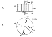
本願第1番目の発明による抗力形風車の実施例は、図7に示す従来の抗力形風車の場合と同様に、ロータ軸1と、そのロータ軸1にそれぞれの板面が当該ロータ軸1の軸線と直交する面上に延長するように且つ互いに相対向するように固定して取り付けられた第1及び第2の円形端板2A及び2Bと、ともに半円筒体3(円筒体(これをAとする)がその軸を含む面に沿って2分割されて得られたのと同様の構成を有する)でなり且つ第1及び第2の円形端板2A及び2B間にロータ軸1の軸線の周りに等角間隔を保ち且つロータ軸1の軸線からみて等しい距離を保って半円筒体3の軸線(円筒体Aでみた軸線と同じ)がロータ軸1の軸線と平行になるように固定して配された複数n個、例えば複数4個の第1、第2、第3及び第4のブレード4A、4B、4C及び4Dとを有し、そして、この場合、第1、第2、第3及び第4のブレード4A、4B、4C及び4Dの第1及び第2の円形端板2A及び2B側の端部のそれぞれと第1及び第2の円形端板2A及び2Bのそれぞれとの間が気密に保たれている、という構成を有する。
Next, an embodiment of a drag type wind turbine according to the first invention of the present application will be described with reference to FIGS.
As in the case of the conventional drag type wind turbine shown in FIG. 7, the embodiment of the drag type wind turbine according to the first invention of the present application is the same as that of the conventional drag type wind turbine. The first and second
しかしながら、本願第1番目の発明による抗力形風車の実施例は、そのような構成を有する抗力形風車において、第1及び第2の円形端板2A及び2B間に、複数4個の第1、第2、第3及び第4の平らな案内板5A、5B、5C、及び5Dが、第1、第2、第3及び第4のブレード4A、4B、4C及び4Dの開口端面側においてそれら第1、第2、第3及び第4のブレード4A、4B、4C及び4Dの半円筒体3の軸線(円筒体Aでみた軸線と同じ)を含む当該第1、第2、第3及び第4のブレード4A、4B、4C及び4Dの開口端面に対し垂直な面上にそれぞれ延長するように第1、第2、第3及び第4のブレード4A、4B、4C及び4Dの半円筒体3から離間して固定配設され、そして、この場合、第1、第2、第3及び第4の案内板5A、5B、5C及び5Dの第1及び第2の円形端板2A及び2B側の端部のそれぞれと第1及び第2の円形端板2A及び2Bのそれぞれとの間が気密に保たれている、という構成を有する。
この場合、第1及び第2の円形端板2A及び2Bは、より具体的には、ともに例えば100mmの直径を有し且つ互いに例えば106mmの内側間隔を保っている。
However, the embodiment of the drag-type wind turbine according to the first invention of the present application is a drag-type wind turbine having such a configuration, and includes a plurality of first, second
In this case, more specifically, the first and second
また、第1、第2、第3及び第4のブレード4A、4B、4C及び4Dの半円筒体3は、より具体的には、例えば23mmの内径半径を有し且つ軸がロータ軸1の軸線との間で例えば75mmの距離を保っている。
The first, second, third, and
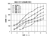
また、第1、第2、第3及び第4の案内板5A、5B、5C及び5Dは、より具体的には、第1及び第2の円形端板2A及び2B間の内側間隔と同じ有効長さと、半円筒体3の内面半径に近い例えば25mmの幅と、例えば2mmの薄い厚さとを有する四辺形でなるとともに、半円筒体3側の端面と半円筒体3の内面との間で、例えば、38mm(図3A)または22mm(図3B)、14mm(図3C)もしくは6mm(図3D)の間隔を保っている。
More specifically, the first, second, third, and
以上で本願第1番目の発明による抗力形風車の実施例の構成が明らかとなった。
このような構成を有する本願第1番目の発明による抗力形風車の実施例によれば、それが第1、第2、第3及び第4の案内板5A、5B、5C及び5Dを有することを除いて、図7に示す従来の抗力形風車の場合と同様の構成を有するので、第1、第2、第3及び第4のブレード4A、4B、4C及び4Dが、その半円筒体3の内面で、風を受けることによって、ロータ軸1に有効な回転トルクを発生させるということで、風車としての機能を呈するが、第1、第2、第3及び第4の案内板5A、5B、5C及び5Dを有し、それらによって、風を、図2に示すように、第1、第2、第3及び第4のブレード4A、4B、4C及び4Dの半円筒体3内に案内するので、図4に、ロータ軸1の風速に対する回転数の測定結果を示しているように、第1、第2、第3及び第4の案内板5A、5B、5C及び5Dを有しない図7に示す従来の抗力形風車の場合、及び第1、第2、第3及び第4の案内板5A、5B、5C及び5Dが第1、第2、第3及び第4のブレード4A、4B、4C及び4Dの半円筒体3から離間していない場合(間隔0mmの場合)に比し、ロータ軸1に格段的に高い回転トルクを発生させることができる。
Thus, the configuration of the embodiment of the drag type wind turbine according to the first invention of the present application has been clarified.
According to the embodiment of the drag-type wind turbine according to the first invention of this application having such a configuration, it has first, second, third and
次に、図5を伴って、本願第2番目の発明による抗力形風車の実施例を述べよう。
本願第2番目の発明による抗力形風車の実施例は、図8に示す従来の抗力形風車の場合と同様に、ロータ軸1と、そのロータ軸1にそれぞれの板面が当該ロータ軸1の軸線と直交する面上に延長するように且つ互いに相対向するように固定して取り付けられた第1及び第2の円形端板2A及び2Bと、ともに半円筒体3(円筒体(これをAとする)がその軸を含む面に沿って2分割されて得られたのと同様の構成を有する)でなり且つ第1及び第2の円形端板2A及び2B間にロータ軸1の軸線の周りに等角間隔を保ち且つロータ軸1の軸線からみて等しい距離を保って半円筒体3の軸線(円筒体Aでみた軸線と同じ)がロータ軸1の軸線と平行になるように固定して配された第1及び第2のブレード4A及び4Bとを有し、そして、この場合、第1及び第2のブレード4A及び4Bの半円筒体3の軸(円筒体Aでみた軸と同じ)間間隔が当該半円筒体3の内面半径の1倍以上、2倍未満であり、また、第1及び第2のブレード4A及び4Bの第1及び第2の円形端板2A及び2B側の端部のそれぞれと第1及び第2の円形端板2A及び2Bのそれぞれとの間が気密に保たれている、という構成を有する。
Next, an embodiment of a drag type wind turbine according to the second invention of the present application will be described with reference to FIG.
As in the case of the conventional drag type wind turbine shown in FIG. 8, the embodiment of the drag type wind turbine according to the second invention of the present application is the same as that of the conventional rotor type wind turbine. The first and second
しかしながら、本願第2番目の発明による抗力形風車の実施例は、そのような構成を有する抗力形風車において、第1及び第2の円形端板2A及び2B間に、第1及び第2の平らな案内板5A及び5Bが、第1及び第2のブレード4A及び4Bの開口端面側においてその第1及び第2のブレード4A及び4Bの半円筒体3の軸線(円筒体Aでみた軸線と同じ)を含む当該第1及び第2のブレード4A及び4Bの開口端面に対し垂直な面上にそれぞれ延長するように第1及び第2のブレード4A及び4Bの半円筒形3から離間して固定配設され、そして、この場合、第1及び第2のブレード4A及び4Bの第1及び第2の円形端板2A及び2B側の端部のそれぞれと第1及び第2の円形端板2A及び2Bのそれぞれとの間に気密が保たれている、という構成を有する。
However, an embodiment of the drag type wind turbine according to the second invention of the present application is a drag type wind turbine having such a configuration, in which the first and second flat plates are interposed between the first and second
以上が、本願第2番目の発明による抗力形風車の実施例の構成である。
このような構成を有する本願第2番目の発明による抗力形風車の実施例によれば、それが、本願第1番目の発明による抗力形風車の第1〜第4の案内板5A〜5Dに対応する第1及び第2の案内板5A及び5Bを有することを除いて、図8に示す従来の抗力形風車の場合と同様の構成を有するので、詳細説明は省略するが、本願第1番目の発明による抗力形風車の実施例で述べたと同様の優れた作用・効果を得ることができることは明らかである。
The above is the configuration of the embodiment of the drag type wind turbine according to the second invention of the present application.
According to the embodiment of the drag type wind turbine according to the second invention of the present application having such a configuration, it corresponds to the first to
次に、図6を伴って、本願第3番目の発明による抗力形風車の実施例を述べよう。
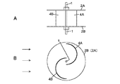
本願第3番目の発明による抗力形風車の実施例は、図9に示す従来の抗力形風車の場合と同様に、ロータ軸1と、そのロータ軸1にそれぞれの板面が当該ロータ軸1の軸線と直交する面上に延長するように且つ互いに相対向するように固定して取り付けられた第1及び第2の円形端板2A及び2Bと、ともにロータ軸1の軸線と直交する横断面でみて直線上に延長しているロータ軸1の軸線側の平らな板体部aとそのロータ軸1の軸線側とは反対側の遊端からそれと一体にロータ軸1の軸線と直交する横断面でみて折り返すように湾曲している線上に延長している湾曲板部bとを有し且つ第1及び第2の円形端板2A及び2B間にロータ軸1の周りに等角間隔を保ち且つロータ軸1の軸線からみて等しい距離を保って板体部a及び湾曲板部bの板面がロータ軸1の軸線と平行になるように固定して配された第1及び第2のブレード4A及び4Bとを有し、そして、この場合、第1のブレード4A及び4Bの板体部aが互いに対向し、また、第1及び第2のブレード4A及び4Bの第1及び第2の円形端板2A及び2B側の端部のそれぞれと第1及び第2の円形端板2A及び2Bのそれぞれとの間が気密に保たれている、という構成を有する。
Next, an embodiment of a drag type wind turbine according to the third invention of the present application will be described with reference to FIG.
As in the case of the conventional drag type wind turbine shown in FIG. 9, the embodiment of the drag type wind turbine according to the third invention of the present application is similar to the case of the conventional drag type wind turbine. The first and second
しかしながら、本願第3番目の発明による抗力形風車の実施例は、このような構成を有する抗力形風車において、第1及び第2の円形端板2A及び2B間に、第1及び第2の平らな案内板5A及び5Bが、第1及び第2のブレード4A及び4Bの開口端面側においてその第1及び第2のブレード4A及び4Bの開口端面のロータ軸1の軸線と直交する横断面でみた中央点またはその近傍点を通るロータ軸1の軸を含む当該第1及び第2のブレード4A及び4Bの開口端面に対し垂直なまたは傾斜している面上にそれぞれ延長するように第1及び第2のグレード2A及び2Bから離間して固定配設され、そして、この場合、第1及び第2のブレード4A及び4Bの第1及び第2の円形端板2A及び2B側の端部のそれぞれと第1及び第2の円形端板2A及び2Bのそれぞれとの間に気密が保たれている、という構成を有する。
However, an embodiment of the drag type wind turbine according to the third invention of the present application is the drag type wind turbine having such a configuration, and the first and second
以上が、本願第3番目の発明による抗力形風車の実施例の構成である。
このような構成を有する本願第3番目の発明による抗力形風車の実施例によれば、それが、本願第1番目の発明による抗力形風車の第1〜第4の案内板5A〜5Dに対応する第1及び第2の案内板5A及び5Bを有することを除いて、図9に示す従来の抗力形風車の場合と同様の構成を有するので、詳細説明は省略するが、本願第1番目の発明による抗力形風車の実施例で述べたと同様の優れた作用・効果を得ることができることは明らかである。
The above is the configuration of the embodiment of the drag type wind turbine according to the third aspect of the present invention.
According to the embodiment of the drag type wind turbine according to the third invention of the present application having such a configuration, it corresponds to the first to
抗力形風車に広く利用することができる。 It can be widely used for drag type windmills.
1 ロータ軸
2A、2B 円形端板
3 半円筒体
4A、4B ブレード
4C、4D ブレード
5A、5B、5C、5D 案内板
1
Claims (3)
上記第1及び第2の円形端板間に、複数n個の第1、第2……第nの平らな案内板が、上記第1、第2……第nのブレードの開口端面側においてそれらの第1、第2……第nのブレードの半円筒体の軸線を含む当該第1、第2……第nのブレードの開口端面に対し垂直な面上にそれぞれ延長するように上記第1、第2……第nのブレードの半円筒体から離間して固定配設され、上記第1、第2……第nの平らな案内板の上記第1及び第2の円形端板側の端部のそれぞれと上記第1及び第2の円形端板のそれぞれとの間が気密に保たれていることを特徴とする抗力形風車。 A rotor shaft and first and second circular end plates fixedly attached to the rotor shaft so that respective plate surfaces extend on a surface orthogonal to the axis of the rotor shaft and face each other And a semi-cylindrical body (having a configuration similar to that obtained by dividing a cylindrical body (referred to as A) into two along a plane including its axis) and the first and second The semi-cylindrical axis (same as the axis seen in the cylinder A) is kept at an equiangular distance between the circular end plates around the axis of the rotor axis and at an equal distance from the axis of the rotor axis. A plurality of n first, second... N th blades arranged in a fixed manner so as to be parallel to the axis of the shaft, and the first, second. Each of the end portions on the first and second circular end plate sides and each of the first and second circular end plates In drag-type wind turbine while is kept airtight,
Between the first and second circular end plates, a plurality of n first, second... Nth flat guide plates are provided on the opening end face side of the first, second... Nth blade. The first, second,..., The first, second,... 1, 2... Fixedly disposed away from the semi-cylindrical body of the n th blade, and the first and second... N th flat guide plates on the first and second circular end plate sides. A drag-type wind turbine characterized in that a space between each of the end portions and each of the first and second circular end plates is kept airtight.
上記第1及び第2の円形端板間に、第1及び第2の平らな案内板が、上記第1及び第2のブレードの開口端面側においてその第1及び第2のブレードの半円筒体の軸線または当該第1及び第2のブレードの開口端面上の当該半円筒体の軸線の近傍の当該軸線と平行な線を含む当該第1及び第2のブレードの開口端面に対し垂直なまたは傾斜している面上にそれぞれ延長するように上記第1及び第2のブレードの半円筒体から離間して固定配設され、上記第1及び第2の平らな案内板の上記第1及び第2の円形端板側の端部のそれぞれと上記第1及び第2の円形端板のそれぞれとの間が気密に保たれていることを特徴とする抗力形風車。 A rotor shaft and first and second circular end plates fixedly attached to the rotor shaft so that respective plate surfaces extend on a surface orthogonal to the axis of the rotor shaft and face each other And a semi-cylindrical body (having a configuration similar to that obtained by dividing a cylindrical body (referred to as A) into two along a plane including its axis) and the first and second The semi-cylindrical axis (same as the axis seen in the cylinder A) is kept at an equiangular distance between the circular end plates around the axis of the rotor axis and at an equal distance from the axis of the rotor axis. First and second blades fixedly arranged so as to be parallel to the axis of the shaft, and a semi-cylindrical shaft of the first and second blades (the same as the shaft seen in the cylindrical body A) ) Is 1 to 2 times the inner radius of the semi-cylindrical body. In drag-type wind turbine between the respective second respective ends of the blades of the first and second circular end plate side and the first and second circular end plate is kept airtight,
Between the first and second circular end plates, the first and second flat guide plates are semi-cylindrical bodies of the first and second blades on the open end face side of the first and second blades. Perpendicular to or inclined with respect to the open end faces of the first and second blades, including a line parallel to the axis of the semicylindrical axis on the open end faces of the first and second blades. The first and second flat guide plates are fixedly disposed to be spaced apart from the first and second blade semi-cylindrical bodies so as to extend on the surfaces of the first and second blades, respectively. A drag-type wind turbine characterized in that a space between each of the end portions on the circular end plate side and each of the first and second circular end plates is kept airtight.
上記第1及び第2の円形端板間に、第1及び第2の平らな案内板が、上記第1及び第2のブレードの開口端面側においてその第1及び第2のブレードの開口端面の上記ロータ軸の軸線と直交する横断面でみた中央点またはその近傍点を通る上記ロータ軸の軸を含む当該第1及び第2のブレードの開口端面に対し垂直なまたは傾斜している面上にそれぞれ延長するように上記第1及び第2のブレードから離間して固定配設され、上記第1及び第2の平らな案内板の上記第1及び第2の円形端板側の端部のそれぞれと上記第1及び第2の円形端板のそれぞれとの間が気密に保たれていることを特徴とする抗力形風車。
A rotor shaft and first and second circular end plates fixedly attached to the rotor shaft so that respective plate surfaces extend on a surface orthogonal to the axis of the rotor shaft and face each other And a flat plate portion on the axis side of the rotor shaft that extends in a straight line as viewed in a cross section orthogonal to the axis of the rotor shaft, and a free end opposite to the axis side of the rotor shaft. And a curved plate portion extending on a curved line so as to be folded back when viewed in a cross section orthogonal to the axis of the rotor shaft, and the rotor between the first and second circular end plates. The plate surfaces of the plate body portion and the curved plate portion are fixed and arranged so as to be parallel to the axis of the rotor shaft while maintaining equiangular intervals around the shaft and maintaining an equal distance when viewed from the axis of the rotor shaft. First and second blades, wherein the first The plate parts of the raid are opposed to each other, and each of the first and second circular end plate side ends of the first and second blades and each of the first and second circular end plates In a drag-type windmill that is kept airtight,
Between the first and second circular end plates, a first and second flat guide plate is provided on the opening end surface side of the first and second blades on the opening end surfaces of the first and second blades. On a plane perpendicular to or inclined with respect to the opening end surfaces of the first and second blades including the axis of the rotor shaft passing through a central point or a point in the vicinity thereof seen in a cross section orthogonal to the axis of the rotor shaft Each of the first and second circular end plate side ends of the first and second flat guide plates is fixedly disposed so as to extend from the first and second blades so as to extend. And a drag type wind turbine characterized in that the space between each of the first and second circular end plates is kept airtight.
Priority Applications (1)
| Application Number | Priority Date | Filing Date | Title |
|---|---|---|---|
| JP2004108174A JP2005291109A (en) | 2004-03-31 | 2004-03-31 | Drag-type windmill |
Applications Claiming Priority (1)
| Application Number | Priority Date | Filing Date | Title |
|---|---|---|---|
| JP2004108174A JP2005291109A (en) | 2004-03-31 | 2004-03-31 | Drag-type windmill |
Publications (1)
| Publication Number | Publication Date |
|---|---|
| JP2005291109A true JP2005291109A (en) | 2005-10-20 |
Family
ID=35324320
Family Applications (1)
| Application Number | Title | Priority Date | Filing Date |
|---|---|---|---|
| JP2004108174A Pending JP2005291109A (en) | 2004-03-31 | 2004-03-31 | Drag-type windmill |
Country Status (1)
| Country | Link |
|---|---|
| JP (1) | JP2005291109A (en) |
Cited By (3)
| Publication number | Priority date | Publication date | Assignee | Title |
|---|---|---|---|---|
| WO2008152721A1 (en) * | 2007-06-14 | 2008-12-18 | Kabushiki Kaisha Win Sakane | Wind-driven generator |
| JP2011058370A (en) * | 2009-09-07 | 2011-03-24 | Junji Takahashi | Savonius wind power generator and savonius wind turbine |
| CN104454368A (en) * | 2014-12-26 | 2015-03-25 | 南京锦铂机电科技有限责任公司 | Novel low-speed wind driven generator |
-
2004
- 2004-03-31 JP JP2004108174A patent/JP2005291109A/en active Pending
Cited By (3)
| Publication number | Priority date | Publication date | Assignee | Title |
|---|---|---|---|---|
| WO2008152721A1 (en) * | 2007-06-14 | 2008-12-18 | Kabushiki Kaisha Win Sakane | Wind-driven generator |
| JP2011058370A (en) * | 2009-09-07 | 2011-03-24 | Junji Takahashi | Savonius wind power generator and savonius wind turbine |
| CN104454368A (en) * | 2014-12-26 | 2015-03-25 | 南京锦铂机电科技有限责任公司 | Novel low-speed wind driven generator |
Similar Documents
| Publication | Publication Date | Title |
|---|---|---|
| EP3318754B1 (en) | Magnus-type thrust generating device | |
| US10288036B2 (en) | Rotor | |
| JP5785181B2 (en) | Turbine | |
| ES2679368T3 (en) | Wind turbine blade that has a lift plate or shaped flow diverter | |
| KR20200000501A (en) | Rotor blade with serrations | |
| CA2822306A1 (en) | Co-axial rotors in a wind turbine and a method of generating energy therefrom | |
| US8562299B2 (en) | Blade for a device for generating energy from a fluid flow | |
| US20250243846A1 (en) | Vehicle and rotor blade | |
| JP6592259B2 (en) | Water turbine propeller rotor | |
| WO2018168689A1 (en) | Rotation device, propulsion device, and power generation device | |
| JP2019078192A5 (en) | ||
| KR102608949B1 (en) | rotor blades | |
| JP2005291109A (en) | Drag-type windmill | |
| KR102471788B1 (en) | rotor for electric generator | |
| JP2018040304A (en) | Horizontal shaft rotor | |
| JP4892716B1 (en) | Wind power generator | |
| JP2015075062A (en) | Axial flow type blade, and wind power generation apparatus using the same | |
| KR102451621B1 (en) | propeller rotor | |
| JP4814186B2 (en) | Drag type windmill | |
| JP2007332871A (en) | Impeller for windmill | |
| JP7488584B2 (en) | Omnidirectional Generator Unit | |
| JP6396674B2 (en) | Wave power generator | |
| TWI697616B (en) | Transverse axis rotor | |
| WO2022054800A1 (en) | Vertical-axis wind turbine and vertical-axis wind turbine power generator | |
| JP5421498B1 (en) | Vertical axis windmill |