KR102471788B1 - rotor for electric generator - Google Patents
rotor for electric generator Download PDFInfo
- Publication number
- KR102471788B1 KR102471788B1 KR1020177029780A KR20177029780A KR102471788B1 KR 102471788 B1 KR102471788 B1 KR 102471788B1 KR 1020177029780 A KR1020177029780 A KR 1020177029780A KR 20177029780 A KR20177029780 A KR 20177029780A KR 102471788 B1 KR102471788 B1 KR 102471788B1
- Authority
- KR
- South Korea
- Prior art keywords
- rotor
- hub
- blade
- diameter
- blades
- Prior art date
Links
Images


Classifications
-
- F—MECHANICAL ENGINEERING; LIGHTING; HEATING; WEAPONS; BLASTING
- F01—MACHINES OR ENGINES IN GENERAL; ENGINE PLANTS IN GENERAL; STEAM ENGINES
- F01D—NON-POSITIVE DISPLACEMENT MACHINES OR ENGINES, e.g. STEAM TURBINES
- F01D5/00—Blades; Blade-carrying members; Heating, heat-insulating, cooling or antivibration means on the blades or the members
- F01D5/12—Blades
- F01D5/14—Form or construction
- F01D5/147—Construction, i.e. structural features, e.g. of weight-saving hollow blades
-
- F—MECHANICAL ENGINEERING; LIGHTING; HEATING; WEAPONS; BLASTING
- F01—MACHINES OR ENGINES IN GENERAL; ENGINE PLANTS IN GENERAL; STEAM ENGINES
- F01D—NON-POSITIVE DISPLACEMENT MACHINES OR ENGINES, e.g. STEAM TURBINES
- F01D5/00—Blades; Blade-carrying members; Heating, heat-insulating, cooling or antivibration means on the blades or the members
- F01D5/02—Blade-carrying members, e.g. rotors
-
- F—MECHANICAL ENGINEERING; LIGHTING; HEATING; WEAPONS; BLASTING
- F03—MACHINES OR ENGINES FOR LIQUIDS; WIND, SPRING, OR WEIGHT MOTORS; PRODUCING MECHANICAL POWER OR A REACTIVE PROPULSIVE THRUST, NOT OTHERWISE PROVIDED FOR
- F03B—MACHINES OR ENGINES FOR LIQUIDS
- F03B13/00—Adaptations of machines or engines for special use; Combinations of machines or engines with driving or driven apparatus; Power stations or aggregates
- F03B13/10—Submerged units incorporating electric generators or motors
-
- F—MECHANICAL ENGINEERING; LIGHTING; HEATING; WEAPONS; BLASTING
- F03—MACHINES OR ENGINES FOR LIQUIDS; WIND, SPRING, OR WEIGHT MOTORS; PRODUCING MECHANICAL POWER OR A REACTIVE PROPULSIVE THRUST, NOT OTHERWISE PROVIDED FOR
- F03B—MACHINES OR ENGINES FOR LIQUIDS
- F03B13/00—Adaptations of machines or engines for special use; Combinations of machines or engines with driving or driven apparatus; Power stations or aggregates
- F03B13/12—Adaptations of machines or engines for special use; Combinations of machines or engines with driving or driven apparatus; Power stations or aggregates characterised by using wave or tide energy
- F03B13/26—Adaptations of machines or engines for special use; Combinations of machines or engines with driving or driven apparatus; Power stations or aggregates characterised by using wave or tide energy using tide energy
- F03B13/264—Adaptations of machines or engines for special use; Combinations of machines or engines with driving or driven apparatus; Power stations or aggregates characterised by using wave or tide energy using tide energy using the horizontal flow of water resulting from tide movement
-
- F—MECHANICAL ENGINEERING; LIGHTING; HEATING; WEAPONS; BLASTING
- F03—MACHINES OR ENGINES FOR LIQUIDS; WIND, SPRING, OR WEIGHT MOTORS; PRODUCING MECHANICAL POWER OR A REACTIVE PROPULSIVE THRUST, NOT OTHERWISE PROVIDED FOR
- F03B—MACHINES OR ENGINES FOR LIQUIDS
- F03B17/00—Other machines or engines
- F03B17/06—Other machines or engines using liquid flow with predominantly kinetic energy conversion, e.g. of swinging-flap type, "run-of-river", "ultra-low head"
- F03B17/061—Other machines or engines using liquid flow with predominantly kinetic energy conversion, e.g. of swinging-flap type, "run-of-river", "ultra-low head" with rotation axis substantially in flow direction
-
- F—MECHANICAL ENGINEERING; LIGHTING; HEATING; WEAPONS; BLASTING
- F03—MACHINES OR ENGINES FOR LIQUIDS; WIND, SPRING, OR WEIGHT MOTORS; PRODUCING MECHANICAL POWER OR A REACTIVE PROPULSIVE THRUST, NOT OTHERWISE PROVIDED FOR
- F03B—MACHINES OR ENGINES FOR LIQUIDS
- F03B3/00—Machines or engines of reaction type; Parts or details peculiar thereto
- F03B3/04—Machines or engines of reaction type; Parts or details peculiar thereto with substantially axial flow throughout rotors, e.g. propeller turbines
-
- F—MECHANICAL ENGINEERING; LIGHTING; HEATING; WEAPONS; BLASTING
- F05—INDEXING SCHEMES RELATING TO ENGINES OR PUMPS IN VARIOUS SUBCLASSES OF CLASSES F01-F04
- F05B—INDEXING SCHEME RELATING TO WIND, SPRING, WEIGHT, INERTIA OR LIKE MOTORS, TO MACHINES OR ENGINES FOR LIQUIDS COVERED BY SUBCLASSES F03B, F03D AND F03G
- F05B2220/00—Application
- F05B2220/30—Application in turbines
- F05B2220/32—Application in turbines in water turbines
-
- F—MECHANICAL ENGINEERING; LIGHTING; HEATING; WEAPONS; BLASTING
- F05—INDEXING SCHEMES RELATING TO ENGINES OR PUMPS IN VARIOUS SUBCLASSES OF CLASSES F01-F04
- F05B—INDEXING SCHEME RELATING TO WIND, SPRING, WEIGHT, INERTIA OR LIKE MOTORS, TO MACHINES OR ENGINES FOR LIQUIDS COVERED BY SUBCLASSES F03B, F03D AND F03G
- F05B2250/00—Geometry
-
- Y—GENERAL TAGGING OF NEW TECHNOLOGICAL DEVELOPMENTS; GENERAL TAGGING OF CROSS-SECTIONAL TECHNOLOGIES SPANNING OVER SEVERAL SECTIONS OF THE IPC; TECHNICAL SUBJECTS COVERED BY FORMER USPC CROSS-REFERENCE ART COLLECTIONS [XRACs] AND DIGESTS
- Y02—TECHNOLOGIES OR APPLICATIONS FOR MITIGATION OR ADAPTATION AGAINST CLIMATE CHANGE
- Y02E—REDUCTION OF GREENHOUSE GAS [GHG] EMISSIONS, RELATED TO ENERGY GENERATION, TRANSMISSION OR DISTRIBUTION
- Y02E10/00—Energy generation through renewable energy sources
- Y02E10/20—Hydro energy
-
- Y—GENERAL TAGGING OF NEW TECHNOLOGICAL DEVELOPMENTS; GENERAL TAGGING OF CROSS-SECTIONAL TECHNOLOGIES SPANNING OVER SEVERAL SECTIONS OF THE IPC; TECHNICAL SUBJECTS COVERED BY FORMER USPC CROSS-REFERENCE ART COLLECTIONS [XRACs] AND DIGESTS
- Y02—TECHNOLOGIES OR APPLICATIONS FOR MITIGATION OR ADAPTATION AGAINST CLIMATE CHANGE
- Y02E—REDUCTION OF GREENHOUSE GAS [GHG] EMISSIONS, RELATED TO ENERGY GENERATION, TRANSMISSION OR DISTRIBUTION
- Y02E10/00—Energy generation through renewable energy sources
- Y02E10/30—Energy from the sea, e.g. using wave energy or salinity gradient
Abstract
수력 발전기용 회전자(10). 상기 회전자(10)는 허브(12) 및 복수의 블레이드(16)를 포함한다. 상기 허브(12)는 원형 단면 형상과 길이방향 회전 축(14)을 갖는다. 상기 복수의 블레이드(16) 각각은 근위 기저부(16a)와 원위 팁(16b)을 갖는다. 각각의 블레이드 기저부(16a)는 상기 허브(12)의 가장 넓은 부분(D1)에서 상기 허브(12)에 장착된다. 상기 블레이드의 상기 팁(16b)의 직경 대 상기 허브(12)의 상기 가장 넓은 부분(D1)의 직경의 비는 약 2:1 미만이다.A rotor (10) for a hydroelectric generator. The rotor 10 includes a hub 12 and a plurality of blades 16 . The hub 12 has a circular cross-sectional shape and a longitudinal axis of rotation 14 . Each of the plurality of blades 16 has a proximal base 16a and a distal tip 16b. Each blade base 16a is mounted to the hub 12 at the widest part D1 of the hub 12 . The ratio of the diameter of the tip 16b of the blade to the diameter of the widest portion D1 of the hub 12 is less than about 2:1.
Description
본 발명은 전기 발전기용 회전자에 관한 것이다.The present invention relates to a rotor for an electric generator.
본 발명은 주로 수력 발전기용 회전자에 사용하기 위해 개발되었다. 이러한 발전기는 물 및 바람과 같은 흐르는 유체의 운동 에너지를 전기 전력으로 변환하는 데 사용된다.The present invention was primarily developed for use in rotors for hydroelectric power generators. These generators are used to convert the kinetic energy of flowing fluids such as water and wind into electrical power.
물 및 바람과 같은 흐르는 유체의 운동 에너지는 전력을 생성하기 위해 바이오 연료 및 화석 연료와 같은 에너지 소스에 대한 대안으로 알려져 있다. 예를 들어, 전기 전력을 생성하는데 사용될 때 유해한 연소 가스를 함께 대기로 배출하는 바이오 연료 및 화석 연료와 달리, 흐르는 유체를 사용하여 전력을 생성하는 것은 대기에 악영향을 전혀 미치지 않거나 거의 미치지 않는다.The kinetic energy of flowing fluids such as water and wind is known as an alternative to energy sources such as biofuels and fossil fuels to generate electrical power. For example, unlike biofuels and fossil fuels, which together release harmful combustion gases into the atmosphere when used to generate electrical power, generating power using flowing fluids has little or no adverse effect on the atmosphere.
풍력을 수확하기 위한 알려진 설비는 일반적으로 낮은 운전 비용을 가지지만, 설치 비용이 비싸고 비교적 낮은 발전 용량을 갖는 경향이 있다. 한편, 예를 들어 조력과 같은 수력을 수확하기 위한 알려진 설비는 비교적 더 높은 발전 용량을 갖는다.Known installations for harvesting wind power generally have low operating costs, but tend to be expensive to install and have relatively low generating capacity. On the other hand, known installations for harvesting hydraulic power, eg tidal power, have comparatively higher generating capacities.
알려진 수력 발전기는 전형적으로 둘 이상의 외측으로 연장되는 블레이드(blade)가 부착된 중심 허브(hub)를 포함하는 회전자를 갖는다. 이 회전자는 회전 일에 대해 구동 샤프트에 의해 전기 전력 변환기(즉, 발전기)에 연결된다. 회전자 블레이드를 지나 흐르는 유체는 회전자를 회전시키고 이 회전자는 변환기를 회전시켜 전기 전력을 생성한다.Known hydroelectric generators typically have a rotor comprising a central hub to which two or more outwardly extending blades are attached. This rotor is connected by a drive shaft to an electrical power converter (i.e. generator) for rotational work. Fluid flowing past the rotor blades rotates the rotor, which rotates the transducer to generate electrical power.
알려진 회전자는 비교적 작은 직경의 허브 및 비교적 길고 가느다란 블레이드들을 갖는다. 이 블레이드들은 또한 비교적 높은 종횡비(이는 블레이드 길이 대 블레이드 폭의 비임)를 갖는다. 이러한 블레이드들은 높은 동작 부하를 받고 난류(turbulence)인 유체 흐름에서 극한 굽힘 모멘트를 받기 쉽다. 이것은 일반적으로 블레이드를 파손시킨다.Known rotors have relatively small diameter hubs and relatively long, slender blades. These blades also have a relatively high aspect ratio (which is the ratio of blade length to blade width). These blades are subjected to high operating loads and are subject to ultimate bending moments in turbulent fluid flow. This usually breaks the blade.
본 발명의 목적은 상기 단점을 실질적으로 극복하거나 적어도 개선하는 것이다.It is an object of the present invention to substantially overcome or at least ameliorate the above disadvantages.
제1 양태에서, 본 발명은, 수력 발전기용 회전자로서, 상기 회전자는,In a first aspect, the present invention is a rotor for a hydroelectric generator, the rotor comprising:
원형 단면 형상과 길이방향 회전 축을 갖는 허브, 및A hub having a circular cross-sectional shape and a longitudinal axis of rotation, and
복수의 블레이드로서, 상기 블레이드의 각각은 근위 기저부(proximal root) 및 원위 팁(distal tip)을 갖고, 상기 블레이드 기저부의 각각은 상기 허브의 가장 넓은 부분에서 상기 허브에 장착되는, 상기 복수의 블레이드를 포함하되,a plurality of blades, each of the blades having a proximal root and a distal tip, each blade root being mounted to the hub at its widest portion; include,
상기 블레이드의 상기 팁의 직경 대 상기 허브의 상기 가장 넓은 부분의 직경의 비는 약 2:1 미만인, 상기 회전자를 제공한다.wherein the ratio of the diameter of the tip of the blade to the diameter of the widest portion of the hub is less than about 2:1.
바람직하게는, 상기 블레이드의 상기 팁의 직경 대 상기 허브의 상기 가장 넓은 부분의 직경의 비는 약 1.2:1 내지 2:1이다.Preferably, the ratio of the diameter of the tip of the blade to the diameter of the widest portion of the hub is between about 1.2:1 and 2:1.
바람직하게는, 상기 블레이드의 상기 팁의 직경 대 상기 허브의 상기 가장 넓은 부분의 직경의 비는 약 1.5:1 또는 1.6:1이다.Preferably, the ratio of the diameter of the tip of the blade to the diameter of the widest portion of the hub is about 1.5:1 or 1.6:1.
일 실시예에서, 상기 블레이드의 상기 팁의 직경은 3.6 미터 내지 4.8 미터이고, 그리고 상기 허브의 상기 가장 넓은 부분의 직경은 2.4 미터이다.In one embodiment, the diameter of the tip of the blade is between 3.6 meters and 4.8 meters, and the diameter of the widest portion of the hub is 2.4 meters.
다른 실시예에서, 상기 블레이드의 상기 팁의 직경은 30 미터 내지 32 미터이고, 그리고 상기 허브의 상기 가장 넓은 부분의 직경은 20 미터이다.In another embodiment, the diameter of the tip of the blade is between 30 meters and 32 meters, and the diameter of the widest part of the hub is 20 meters.
상기 블레이드 기저부들 각각이 상기 허브에 장착된 구역에서, 상기 허브 표면의 프로파일 반경은 바람직하게는 상기 허브의 상기 가장 넓은 부분의 반경과 같은 크기와 상기 가장 넓은 부분의 반경의 1/6 크기 사이이다.In the area where each of the blade bases is mounted on the hub, the profile radius of the hub surface is preferably between the same size as the radius of the widest part of the hub and one-sixth of the radius of the widest part of the hub. .
본 발명의 바람직한 실시예는 첨부된 도면을 참조하여 단지 예로서 설명될 것이다.
도 1은 회전자의 제1 실시예의 정면도;
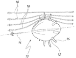
도 2는 스트림 라인(stream line)을 갖는 도 1에 도시된 회전자의 사시도; 및
도 3은 회전자의 제2 실시예를 갖는 수력 발전기의 측단면도.Preferred embodiments of the present invention will be described by way of example only with reference to the accompanying drawings.
1 is a front view of a first embodiment of a rotor;
Fig. 2 is a perspective view of the rotor shown in Fig. 1 with a stream line; and
3 is a cross-sectional side view of a hydroelectric generator having a second embodiment of a rotor;
도 1 및 도 2는 조류 흐름 환경에 설치하기에 적합한 수력 발전기용 회전자(10)를 도시한다. 회전자(10)는 원형 단면 형상과 길이방향 회전 축(14)을 갖는 허브(12)를 포함한다. 회전자(10)는 7개의 등간격으로 이격된 블레이드(16)를 또한 포함한다. 허브(10)는 유리 보강된 플라스틱(glass reinforced plastic: GRP) 또는 금속 스킨으로 형성되고, 블레이드(16)는 탄소 섬유 금속 복합체로 형성된다.1 and 2 show a
각각의 블레이드(16)는 근위 기저부(16a)와 원위 팁(16b)을 갖는다. 각각의 블레이드(16)는 그 기저부(16a)에서 허브(14)의 가장 넓은 부분에서 허브(14)에 장착된다. 허브(14)의 가장 넓은 부분의 직경은 직경(D1)으로 도시되어 있다. 블레이드(16)들의 팁(16b)들의 직경은 직경(D2)으로 도시되어 있다. 도시된 실시예에서, 직경들 사이의 비, 즉, D2:D1은 약 1.4:1이다.Each
도 2는 유체가 허브(12) 둘레를 흐를 때 그 속도가 증가하는 것을 나타내는 유체 흐름 스트림 라인(18)에 대한 회전자(10)를 도시한다. 유체가 가속되고 국부 속도가 증가할 때, 국부 압력은 감소한다. 이러한 압력 감소는 유체가 허브(12) 둘레에 집중되게 한다. 그 결과, 유체의 자유 스트림 에너지는 블레이드(16) 구역에 집중된다.FIG. 2 shows the
상기 D2:D1 비를 기술하는 또 다른 방법은 허브(12)의 직경이 블레이드(16)의 길이에 비해 비교적 크다는 것이다. 비교적 큰 허브 직경(D1)은 다음의 이중 기능, 즉, 1. 지나가는 물 스트림에 에너지를 집중시키는 기능; 및 2. 더 낮은 종횡비를 각각 갖는 비교적 더 많은 개수의 더 작고 강한 블레이드(16)를 지지하는 기능을 유리하게 제공한다.Another way to describe the D2:D1 ratio is that the diameter of the
후자의 문제와 관련하여, 기저부에서 굽힘 모멘트는 블레이드의 종횡비의 함수이다. 예를 들어, 8:1의 종횡비를 갖는 블레이드는 기저부에서의 응력 값이 4:1의 종횡비를 갖는 동일한 블레이드보다 16배 더 높다. 비교적 작은 직경의 허브를 갖는 알려진 3-블레이드 회전자에서, 블레이드들은 허브의 직경 제한 때문에 기저부에서 제한된 코드 길이만을 가질 수 있다. 코드 길이의 이러한 제한은 이상적인 호일 구획에 요구되는 것보다 충분한 강도를 제공하기 위해 블레이드 기저부의 두께가 증가되어야 한다는 것을 의미한다.Regarding the latter problem, the bending moment at the base is a function of the aspect ratio of the blade. For example, a blade with an 8:1 aspect ratio has a stress value at the base that is 16 times higher than the same blade with an aspect ratio of 4:1. In known 3-blade rotors with relatively small diameter hubs, the blades can only have a limited chord length at the base because of the diameter limitations of the hub. This limitation of chord length means that the thickness of the blade base must be increased to provide sufficient strength than is required for an ideal foil section.
비교적 더 작은 허브에 장착된 비교적 더 긴 블레이드는 또한 주어진 RPM에 대해 더 낮은 겉보기 속도(apparent velocity)와 더 낮은 토크 반경을 초래한다.A relatively longer blade mounted on a relatively smaller hub also results in a lower apparent velocity and lower torque radius for a given RPM.
더 두꺼운 기저부는, 특히 블레이드의 하부 1/3 지점에서, 더 낮은 겉보기 속도와 더 낮은 토크 반경과 결합하여, 이러한 (알려진) 3-블레이드 회전자의 총 동력에 더 낮은 기여도를 초래한다. 이것은 더 작은 허브/더 큰 3-블레이드 구성에서 블레이드의 외측 1/3 지점이 일의 63%를 차지하기 때문이다. 이것은 전체 표면적의 56%를 차지하는 블레이드의 외측 30%, 및 무시할 수 있는 전력을 생성하는 블레이드의 내측 30%의 스위프(sweep) 영역의 결합이다.The thicker base, especially in the lower third of the blade, combined with the lower apparent speed and lower torque radius, results in a lower contribution to the total power of this (known) three-blade rotor. This is because in the smaller hub/larger 3-blade configuration, the outer third of the blade does 63% of the work. This is the combination of the outer 30% of the blade accounting for 56% of the total surface area, and the sweep area of the inner 30% of the blade generating negligible power.
이와 달리, 회전자(10)의 구성(즉, 비교적 더 큰 허브(14), 비교적 더 짧은 블레이드(16)들, 비교적 많은 개수의 블레이드(16))은 내측 2/3 구역에서 유체 흐름을 방향 전환(redirect)하여 집중시키고, 외측 1/3 구역을 통해 유체를 가속시켜 여기서 동력의 100%가 추출될 수 있다. 이것은 유리하게는, 블레이드(16)들이 최대 용량으로 동작하면서도 더 낮은 응력 부하를 경험한다는 것을 의미한다.In contrast, the configuration of the rotor 10 (i.e., relatively
다시 말해, 회전자(10)의 D2:D1 비는 블레이드(16)들이 허브 둘레 가속 영역에서 동작하는데 이상적인 블레이드 길이를 갖는 블레이드(16)들을 이 허브(12) 둘레 가속 영역에 배치한다. 블레이드들이 허브 직경에 비해 너무 긴 경우 블레이드들의 팁들은 대신 유체 가속이 없는 구역에서 동작하므로 양의 토크(positive torque)에 기여하지 않는다.In other words, the D2:D1 ratio of the
도 3은 회전자(32)의 제2 실시예에 따른 수력 발전기(30)를 도시한다. 회전자(32)는 허브(34) 및 10개의 블레이드(36)를 갖는다. 도 3은 또한 블레이드 기저부 장착 빔(38), 블레이드 장착 허브(40), 고정된 주 스핀들(42), 구동 샤프트(44), 기어 박스(46), 지지 빔(48), 방수 밀봉부(50), 베어링(52), 및 회전 발전기(54)를 도시한다. 빔(48)은 발전기(30)를 부유식 전개 리그(floating deployment rig)(미도시)에 연결하는데 사용된다.3 shows a
또한, 도 3에는 허브(34)와 블레이드(36)들이 연결된 구역에서 허브(34)의 프로파일 반경인 반경(R)이 도시되어 있다. 도시된 바람직한 구성에서, 반경(R)은 허브(34)의 반경의 1/6이다. 이 특정 비는 난기류를 피하면서 흐름 가속을 최대화한다.Also, FIG. 3 shows the radius R, which is the profile radius of the
발전기(30)의 하나의 바람직한 형태는 다음과 같은 사양을 갖는다:One preferred form of
허브 직경(D1): 2.4 미터Hub Diameter (D1): 2.4 meters
블레이드 팁 직경(D2): 4.8 미터 내지 3.6 미터Blade tip diameter (D2): 4.8 meters to 3.6 meters
전력 생산 범위: 50 내지 300 kWs Power production range: 50 to 300 kWs
유속 범위: 1.2 내지 4.2 m/초Flow velocity range: 1.2 to 4.2 m/sec
블레이드 팁 직경 대 허브 직경 비: 2:1 내지 1.5:1Blade tip diameter to hub diameter ratio: 2:1 to 1.5:1
발전기(30)의 다른 바람직한 형태는 다음과 같은 사양을 갖는다:Another preferred form of
허브 직경(D1): 20 미터Hub diameter (D1): 20 meters
블레이드 팁 직경(D2): 32 내지 30 미터Blade tip diameter (D2): 32 to 30 meters
전력 생산 범위: 0.5 내지 5 MW Power production range: 0.5 to 5 MW
유속 범위: 1.2 내지 4.0 m/초Flow velocity range: 1.2 to 4.0 m/sec
블레이드 팁 직경 대 허브 직경 비: 1.6:1 내지 1.5:1Blade tip diameter to hub diameter ratio: 1.6:1 to 1.5:1
전술한 (비교적 더 큰) 직경 허브 대 (비교적 더 작은) 직경 블레이드의 비 때문에 수력 발전기에는 여러 장점이 있다.Because of the aforementioned ratio of (relatively larger) diameter hubs to (relatively smaller) diameter blades, hydroelectric generators have several advantages.
첫째, 유체 스트림의 에너지는 작은 블레이드 세트를 통해 집중되고 가속되어 회전자의 효율을 향상시킨다.First, the energy of the fluid stream is concentrated and accelerated through a small set of blades to improve the efficiency of the rotor.
둘째, 다수의(예를 들어, 7개의) 더 작은 블레이드의 전체 체적은 작은 개수의(예를 들어, 3개의) 대형 블레이드의 체적보다 더 작아서, 제조 비용을 낮춘다.Second, the total volume of a number of (eg, seven) smaller blades is smaller than that of a small number (eg, three) of larger blades, lowering manufacturing costs.
셋째, 더 작은 블레이드는 더 낮은 종횡비를 가져서, 블레이드 기저부의 굽힘 모멘트를 낮추고 블레이드 파손 가능성을 낮춘다.Third, smaller blades have a lower aspect ratio, which lowers the bending moment at the base of the blade and lowers the chance of blade breakage.
넷째, 더 작은 블레이드 상으로 흐름이 입사하는 속도 및 입사하는 입사각은 블레이드의 폭(span)에 걸쳐 균일한 값에 더 가깝다. 이것은 그 폭에 걸쳐 블레이드의 제로 비틀림(twist)에 거의 가깝고, 이에 의해 블레이드 비틀림에 의한 성능 손실 없이 피치(pitch)를 제어하여 블레이드들이 관절식으로 연결될 수 있다. 또한, 동작 동안 피치를 조절할 수 있는 능력은 회전자가 흐름 스트림 속도와 관계 없이 일정한 rpm에서 동작할 수 있다는 것을 의미한다. 이에 의해 발전기는 전기 그리드(electrical grid)에 직접 연결된 채 일정 rpm에서 동작할 수 있어서, 전기 주파수 인버터 구동 시스템의 비용을 제거한다.Fourth, the rate of incidence of the flow on the smaller blade and the angle of incidence are closer to uniform values over the span of the blade. This is close to zero twist of the blade across its width, whereby the blades can be articulated with controlled pitch without performance loss due to blade twist. Additionally, the ability to adjust the pitch during operation means that the rotor can operate at a constant rpm regardless of the flow stream speed. This allows the generator to operate at constant rpm while directly connected to the electrical grid, eliminating the cost of an electrical frequency inverter drive system.
다섯째, 빠르게 흐르는 조류 흐름에서 동작하는 회전자는 스트림에서 높은 레벨의 난류를 받는다. 더 큰 허브 둘레로 물의 흐름이 가속되는 작용은 블레이드 구역 내로 난류의 레벨을 감소시킨다. 이것은 난류가 많은 환경에서 블레이드의 존속성을 향상시킨다.Fifth, rotors operating in fast-flowing tidal streams are subject to high levels of turbulence in the stream. The action of accelerating the flow of water around the larger hub reduces the level of turbulence into the blade region. This improves the survivability of the blade in turbulent environments.
본 발명이 바람직한 실시예를 참조하여 설명되었지만, 본 발명을 다른 형태로 구현할 수 있음은 이 기술 분야에 통상의 지식을 가진 자라면 이해할 수 있을 것이다.Although the present invention has been described with reference to preferred embodiments, it will be understood by those skilled in the art that the present invention can be implemented in other forms.
Claims (21)
원형 단면과 길이방향 축을 갖는 형상으로 형성된 허브(hub)로서, 상기 허브의 형상은 상기 허브에 국부적으로 흐르는 유체의 압력을 상기 자유 스트림 내 유체의 균형 압력에 비해서 상대적으로 감소시키도록 조정되는, 상기 허브, 및
복수의 블레이드(blade)로서, 상기 블레이드의 각각은 근위 기저부(proximal root) 및 원위 팁(distal tip)을 갖고, 상기 블레이드의 기저부의 각각은 가장 넓은 부분에서 상기 허브에 장착되는, 상기 복수의 블레이드를 포함하되,
상기 블레이드의 상기 팁의 직경 대 상기 허브의 상기 가장 넓은 부분의 직경의 비는 2:1 미만이고,
상기 허브를 측면(lateral side)에서 보았을 때 상기 허브의 표면의 프로파일 반경은, 상기 블레이드의 기저부 각각이 상기 허브에 장착된 구역에서, 상기 허브의 상기 가장 넓은 부분의 반경과 같은 크기와 상기 가장 넓은 부분의 반경의 1/6 크기 사이에 있는, 수력 발전기용 회전자.As a rotor for a hydroelectric generator suitable for installation in a free stream,
A hub formed in a shape having a circular cross-section and a longitudinal axis, the shape of the hub being adapted to reduce the pressure of fluid flowing locally to the hub relative to the balancing pressure of the fluid in the free stream. herbs, and
A plurality of blades, each having a proximal root and a distal tip, each root of the blades being mounted to the hub at its widest point. Including,
the ratio of the diameter of the tip of the blade to the diameter of the widest portion of the hub is less than 2:1;
When the hub is viewed from the lateral side, the profile radius of the surface of the hub, in the area where each base of the blade is mounted on the hub, is the same as the radius of the widest part of the hub and the widest A rotor for a hydroelectric generator, between 1/6 of the radius of the part.
Applications Claiming Priority (3)
| Application Number | Priority Date | Filing Date | Title |
|---|---|---|---|
| AU2015900950 | 2015-03-17 | ||
| AU2015900950A AU2015900950A0 (en) | 2015-03-17 | A rotor for an electricity generator | |
| PCT/AU2016/000091 WO2016145477A1 (en) | 2015-03-17 | 2016-03-16 | A rotor for an electricity generator |
Publications (2)
| Publication Number | Publication Date |
|---|---|
| KR20180004713A KR20180004713A (en) | 2018-01-12 |
| KR102471788B1 true KR102471788B1 (en) | 2022-11-28 |
Family
ID=56918161
Family Applications (1)
| Application Number | Title | Priority Date | Filing Date |
|---|---|---|---|
| KR1020177029780A KR102471788B1 (en) | 2015-03-17 | 2016-03-16 | rotor for electric generator |
Country Status (15)
| Country | Link |
|---|---|
| US (3) | US20180073367A1 (en) |
| EP (1) | EP3271570A4 (en) |
| JP (1) | JP6954739B2 (en) |
| KR (1) | KR102471788B1 (en) |
| CN (1) | CN106460769A (en) |
| AU (2) | AU2016232976B2 (en) |
| BR (1) | BR112017019775A2 (en) |
| CA (1) | CA3017762A1 (en) |
| CL (1) | CL2017002352A1 (en) |
| HK (1) | HK1249771A1 (en) |
| NZ (1) | NZ736092A (en) |
| PH (1) | PH12017501682A1 (en) |
| SG (2) | SG11201603713TA (en) |
| WO (1) | WO2016145477A1 (en) |
| ZA (1) | ZA201706827B (en) |
Families Citing this family (4)
| Publication number | Priority date | Publication date | Assignee | Title |
|---|---|---|---|---|
| EP4140872A1 (en) * | 2020-05-21 | 2023-03-01 | Korea Shipbuilding & Offshore Engineering Co., Ltd. | Variable-pitch propeller having optimal hub-to-tip diameter ratio |
| US11286779B2 (en) | 2020-06-03 | 2022-03-29 | Honeywell International Inc. | Characteristic distribution for rotor blade of booster rotor |
| US20230041561A1 (en) * | 2021-07-20 | 2023-02-09 | Robert J Evans | Systems and Methods for a Hydrokinetic Micro Powerplant |
| WO2023057971A1 (en) | 2021-10-07 | 2023-04-13 | Bluenergy Solutions Pte. Ltd. | Electricity generation system |
Citations (1)
| Publication number | Priority date | Publication date | Assignee | Title |
|---|---|---|---|---|
| JP2010001784A (en) * | 2008-06-19 | 2010-01-07 | Ogo Tetsuya | Fluid vehicle with large-diameter spinner |
Family Cites Families (17)
| Publication number | Priority date | Publication date | Assignee | Title |
|---|---|---|---|---|
| US2068792A (en) * | 1935-06-15 | 1937-01-26 | Dekker Adriaan Jan | Screw propeller, turbine rotor, and like device |
| SU430702A1 (en) * | 1972-01-12 | 1978-04-25 | Ленинградский Металлический Завод Им. Хх11 Съезда Кпсс | Method of operating rotary-vane hydraulic machine |
| GB1574379A (en) * | 1977-08-24 | 1980-09-03 | English Electric Co Ltd | Turbines and like rotary machines |
| JPS5818565A (en) * | 1981-07-27 | 1983-02-03 | Tsuchiya Riyuuko | Universal turbine |
| US5137417A (en) * | 1991-06-12 | 1992-08-11 | Lund Arnold M | Wind energy conversion system |
| GB0510417D0 (en) * | 2005-05-21 | 2005-06-29 | Rotech Holdings Ltd | Improved turbine |
| EP2013474A2 (en) * | 2006-04-28 | 2009-01-14 | Swanturbines Limited | Tidal current turbine |
| US7789629B2 (en) * | 2006-12-07 | 2010-09-07 | Verdant Power | Non-fouling kinetic hydro power system axial-flow blade tip treatment |
| CA2643587A1 (en) * | 2008-11-10 | 2010-05-10 | Organoworld Inc. | Turbine annular axial rotor |
| WO2011035208A1 (en) | 2009-09-19 | 2011-03-24 | Salomo Murtonen | Streamlined wind turbine optimized for laminar layer |
| CN201851261U (en) * | 2010-09-08 | 2011-06-01 | 梁思武 | Impeller of multi-stage water turbine |
| EP2630366B1 (en) * | 2010-10-22 | 2018-07-11 | Wave Power Renewables Limited | Turbine rotor assembly |
| JP5048882B1 (en) * | 2012-03-28 | 2012-10-17 | 株式会社センリョウ | Running water power generator |
| CN102777314B (en) * | 2012-06-26 | 2015-04-22 | 浙江大学宁波理工学院 | Tidal stream energy axial flow power generating device |
| CN103573529B (en) * | 2012-08-01 | 2017-06-13 | 杭州林黄丁新能源研究院有限公司 | The hydraulic turbine |
| CN103912435B (en) * | 2014-03-27 | 2016-07-06 | 河海大学 | A kind of small power station kaplan turbine runner |
| GB2530048A (en) * | 2014-09-10 | 2016-03-16 | Rolls Royce Plc | A self-rectifying turbine |
-
2016
- 2016-03-16 CN CN201680000493.6A patent/CN106460769A/en active Pending
- 2016-03-16 CA CA3017762A patent/CA3017762A1/en active Pending
- 2016-03-16 JP JP2016530010A patent/JP6954739B2/en active Active
- 2016-03-16 KR KR1020177029780A patent/KR102471788B1/en active IP Right Grant
- 2016-03-16 SG SG11201603713TA patent/SG11201603713TA/en unknown
- 2016-03-16 AU AU2016232976A patent/AU2016232976B2/en active Active
- 2016-03-16 BR BR112017019775A patent/BR112017019775A2/en not_active Application Discontinuation
- 2016-03-16 WO PCT/AU2016/000091 patent/WO2016145477A1/en active Application Filing
- 2016-03-16 US US15/558,922 patent/US20180073367A1/en not_active Abandoned
- 2016-03-16 NZ NZ736092A patent/NZ736092A/en unknown
- 2016-03-16 EP EP16764053.1A patent/EP3271570A4/en active Pending
- 2016-03-16 SG SG10202006344QA patent/SG10202006344QA/en unknown
-
2017
- 2017-09-14 PH PH12017501682A patent/PH12017501682A1/en unknown
- 2017-09-15 CL CL2017002352A patent/CL2017002352A1/en unknown
- 2017-10-10 ZA ZA2017/06827A patent/ZA201706827B/en unknown
-
2018
- 2018-03-01 AU AU2018201500A patent/AU2018201500A1/en not_active Abandoned
- 2018-07-12 HK HK18109057.1A patent/HK1249771A1/en unknown
-
2020
- 2020-10-22 US US17/078,049 patent/US11767762B2/en active Active
-
2023
- 2023-08-24 US US18/455,587 patent/US20230399952A1/en active Pending
Patent Citations (1)
| Publication number | Priority date | Publication date | Assignee | Title |
|---|---|---|---|---|
| JP2010001784A (en) * | 2008-06-19 | 2010-01-07 | Ogo Tetsuya | Fluid vehicle with large-diameter spinner |
Also Published As
| Publication number | Publication date |
|---|---|
| CN106460769A (en) | 2017-02-22 |
| JP2018507973A (en) | 2018-03-22 |
| AU2016232976A1 (en) | 2016-12-15 |
| US20180073367A1 (en) | 2018-03-15 |
| CA3017762A1 (en) | 2016-09-22 |
| NZ736092A (en) | 2019-03-29 |
| SG10202006344QA (en) | 2020-08-28 |
| AU2016232976B2 (en) | 2017-12-07 |
| EP3271570A4 (en) | 2018-10-31 |
| BR112017019775A2 (en) | 2018-05-15 |
| JP6954739B2 (en) | 2021-10-27 |
| SG11201603713TA (en) | 2016-10-28 |
| WO2016145477A1 (en) | 2016-09-22 |
| US20230399952A1 (en) | 2023-12-14 |
| US11767762B2 (en) | 2023-09-26 |
| EP3271570A1 (en) | 2018-01-24 |
| KR20180004713A (en) | 2018-01-12 |
| CL2017002352A1 (en) | 2018-05-11 |
| PH12017501682A1 (en) | 2018-03-12 |
| ZA201706827B (en) | 2021-04-28 |
| AU2018201500A1 (en) | 2018-04-19 |
| US20210040857A1 (en) | 2021-02-11 |
| HK1249771A1 (en) | 2018-11-09 |
Similar Documents
| Publication | Publication Date | Title |
|---|---|---|
| US20230399952A1 (en) | Rotor for an electricity generator | |
| US9989033B2 (en) | Horizontal axis wind or water turbine with forked or multi-blade upper segments | |
| JP5785181B2 (en) | Turbine | |
| KR100895038B1 (en) | Swept turbine blade assembly for vertical wind turbine system | |
| EP3613980A1 (en) | Vertical-shaft turbine | |
| JP2013534592A (en) | Vertical axis windmill | |
| AU2008235238B2 (en) | Wind wheel | |
| JP2018507973A5 (en) | ||
| KR20100055594A (en) | Rotor blade for wind turbine and wind turbine therewith | |
| KR20150096553A (en) | Downwind Windpower Generating Apparatus having Swept Blade Tip | |
| WO2013158501A1 (en) | Turbine assembly | |
| JP2019173597A (en) | Water turbine and small hydroelectric generator | |
| KR20130068038A (en) | Aerogenerator formed hole on blade | |
| JP2014145293A (en) | Wind turbine | |
| RU2661225C1 (en) | Spherical orthogonal power unit | |
| EP3329116B1 (en) | Water turbine arrangements | |
| US20180017037A1 (en) | Hub and Rotor Assemby for Wind Turbines with Conjoined Turbine Blades | |
| JP2015203395A (en) | Wave power turbine | |
| KR20130068037A (en) | Aerogenerator attached bump on blade | |
| WO2014091264A1 (en) | Rotor for a wind machine with pneumatic power transmission | |
| RU106919U1 (en) | HIGH POWER WIND POWER PLANT | |
| RU104975U1 (en) | ORTHOGONAL TURBINE | |
| KR20130068039A (en) | Aerogenerator connected slat on blade | |
| JP2016094926A (en) | Axial flow water turbine power generation device | |
| JP2015229953A (en) | Wave power generation turbine |
Legal Events
| Date | Code | Title | Description |
|---|---|---|---|
| A201 | Request for examination | ||
| N231 | Notification of change of applicant | ||
| E902 | Notification of reason for refusal | ||
| E701 | Decision to grant or registration of patent right | ||
| GRNT | Written decision to grant |