JP2005291071A - Exhaust gas purification system and exhaust gas purification method - Google Patents
Exhaust gas purification system and exhaust gas purification method Download PDFInfo
- Publication number
- JP2005291071A JP2005291071A JP2004106440A JP2004106440A JP2005291071A JP 2005291071 A JP2005291071 A JP 2005291071A JP 2004106440 A JP2004106440 A JP 2004106440A JP 2004106440 A JP2004106440 A JP 2004106440A JP 2005291071 A JP2005291071 A JP 2005291071A
- Authority
- JP
- Japan
- Prior art keywords
- exhaust gas
- plasma
- nox
- gas purification
- catalyst
- Prior art date
- Legal status (The legal status is an assumption and is not a legal conclusion. Google has not performed a legal analysis and makes no representation as to the accuracy of the status listed.)
- Pending
Links
Images

Classifications
-
- F—MECHANICAL ENGINEERING; LIGHTING; HEATING; WEAPONS; BLASTING
- F01—MACHINES OR ENGINES IN GENERAL; ENGINE PLANTS IN GENERAL; STEAM ENGINES
- F01N—GAS-FLOW SILENCERS OR EXHAUST APPARATUS FOR MACHINES OR ENGINES IN GENERAL; GAS-FLOW SILENCERS OR EXHAUST APPARATUS FOR INTERNAL-COMBUSTION ENGINES
- F01N3/00—Exhaust or silencing apparatus having means for purifying, rendering innocuous, or otherwise treating exhaust
- F01N3/08—Exhaust or silencing apparatus having means for purifying, rendering innocuous, or otherwise treating exhaust for rendering innocuous
- F01N3/10—Exhaust or silencing apparatus having means for purifying, rendering innocuous, or otherwise treating exhaust for rendering innocuous by thermal or catalytic conversion of noxious components of exhaust
- F01N3/24—Exhaust or silencing apparatus having means for purifying, rendering innocuous, or otherwise treating exhaust for rendering innocuous by thermal or catalytic conversion of noxious components of exhaust characterised by constructional aspects of converting apparatus
- F01N3/28—Construction of catalytic reactors
- F01N3/2803—Construction of catalytic reactors characterised by structure, by material or by manufacturing of catalyst support
- F01N3/2825—Ceramics
- F01N3/2828—Ceramic multi-channel monoliths, e.g. honeycombs
-
- F—MECHANICAL ENGINEERING; LIGHTING; HEATING; WEAPONS; BLASTING
- F01—MACHINES OR ENGINES IN GENERAL; ENGINE PLANTS IN GENERAL; STEAM ENGINES
- F01N—GAS-FLOW SILENCERS OR EXHAUST APPARATUS FOR MACHINES OR ENGINES IN GENERAL; GAS-FLOW SILENCERS OR EXHAUST APPARATUS FOR INTERNAL-COMBUSTION ENGINES
- F01N13/00—Exhaust or silencing apparatus characterised by constructional features
- F01N13/009—Exhaust or silencing apparatus characterised by constructional features having two or more separate purifying devices arranged in series
-
- F—MECHANICAL ENGINEERING; LIGHTING; HEATING; WEAPONS; BLASTING
- F01—MACHINES OR ENGINES IN GENERAL; ENGINE PLANTS IN GENERAL; STEAM ENGINES
- F01N—GAS-FLOW SILENCERS OR EXHAUST APPARATUS FOR MACHINES OR ENGINES IN GENERAL; GAS-FLOW SILENCERS OR EXHAUST APPARATUS FOR INTERNAL-COMBUSTION ENGINES
- F01N3/00—Exhaust or silencing apparatus having means for purifying, rendering innocuous, or otherwise treating exhaust
- F01N3/08—Exhaust or silencing apparatus having means for purifying, rendering innocuous, or otherwise treating exhaust for rendering innocuous
- F01N3/0807—Exhaust or silencing apparatus having means for purifying, rendering innocuous, or otherwise treating exhaust for rendering innocuous by using absorbents or adsorbents
- F01N3/0814—Exhaust or silencing apparatus having means for purifying, rendering innocuous, or otherwise treating exhaust for rendering innocuous by using absorbents or adsorbents combined with catalytic converters, e.g. NOx absorption/storage reduction catalysts
-
- F—MECHANICAL ENGINEERING; LIGHTING; HEATING; WEAPONS; BLASTING
- F01—MACHINES OR ENGINES IN GENERAL; ENGINE PLANTS IN GENERAL; STEAM ENGINES
- F01N—GAS-FLOW SILENCERS OR EXHAUST APPARATUS FOR MACHINES OR ENGINES IN GENERAL; GAS-FLOW SILENCERS OR EXHAUST APPARATUS FOR INTERNAL-COMBUSTION ENGINES
- F01N3/00—Exhaust or silencing apparatus having means for purifying, rendering innocuous, or otherwise treating exhaust
- F01N3/08—Exhaust or silencing apparatus having means for purifying, rendering innocuous, or otherwise treating exhaust for rendering innocuous
- F01N3/0807—Exhaust or silencing apparatus having means for purifying, rendering innocuous, or otherwise treating exhaust for rendering innocuous by using absorbents or adsorbents
- F01N3/0828—Exhaust or silencing apparatus having means for purifying, rendering innocuous, or otherwise treating exhaust for rendering innocuous by using absorbents or adsorbents characterised by the absorbed or adsorbed substances
- F01N3/0842—Nitrogen oxides
-
- F—MECHANICAL ENGINEERING; LIGHTING; HEATING; WEAPONS; BLASTING
- F01—MACHINES OR ENGINES IN GENERAL; ENGINE PLANTS IN GENERAL; STEAM ENGINES
- F01N—GAS-FLOW SILENCERS OR EXHAUST APPARATUS FOR MACHINES OR ENGINES IN GENERAL; GAS-FLOW SILENCERS OR EXHAUST APPARATUS FOR INTERNAL-COMBUSTION ENGINES
- F01N3/00—Exhaust or silencing apparatus having means for purifying, rendering innocuous, or otherwise treating exhaust
- F01N3/08—Exhaust or silencing apparatus having means for purifying, rendering innocuous, or otherwise treating exhaust for rendering innocuous
- F01N3/0892—Electric or magnetic treatment, e.g. dissociation of noxious components
-
- F—MECHANICAL ENGINEERING; LIGHTING; HEATING; WEAPONS; BLASTING
- F01—MACHINES OR ENGINES IN GENERAL; ENGINE PLANTS IN GENERAL; STEAM ENGINES
- F01N—GAS-FLOW SILENCERS OR EXHAUST APPARATUS FOR MACHINES OR ENGINES IN GENERAL; GAS-FLOW SILENCERS OR EXHAUST APPARATUS FOR INTERNAL-COMBUSTION ENGINES
- F01N3/00—Exhaust or silencing apparatus having means for purifying, rendering innocuous, or otherwise treating exhaust
- F01N3/08—Exhaust or silencing apparatus having means for purifying, rendering innocuous, or otherwise treating exhaust for rendering innocuous
- F01N3/10—Exhaust or silencing apparatus having means for purifying, rendering innocuous, or otherwise treating exhaust for rendering innocuous by thermal or catalytic conversion of noxious components of exhaust
- F01N3/105—General auxiliary catalysts, e.g. upstream or downstream of the main catalyst
- F01N3/106—Auxiliary oxidation catalysts
-
- F—MECHANICAL ENGINEERING; LIGHTING; HEATING; WEAPONS; BLASTING
- F01—MACHINES OR ENGINES IN GENERAL; ENGINE PLANTS IN GENERAL; STEAM ENGINES
- F01N—GAS-FLOW SILENCERS OR EXHAUST APPARATUS FOR MACHINES OR ENGINES IN GENERAL; GAS-FLOW SILENCERS OR EXHAUST APPARATUS FOR INTERNAL-COMBUSTION ENGINES
- F01N2240/00—Combination or association of two or more different exhaust treating devices, or of at least one such device with an auxiliary device, not covered by indexing codes F01N2230/00 or F01N2250/00, one of the devices being
- F01N2240/28—Combination or association of two or more different exhaust treating devices, or of at least one such device with an auxiliary device, not covered by indexing codes F01N2230/00 or F01N2250/00, one of the devices being a plasma reactor
-
- F—MECHANICAL ENGINEERING; LIGHTING; HEATING; WEAPONS; BLASTING
- F01—MACHINES OR ENGINES IN GENERAL; ENGINE PLANTS IN GENERAL; STEAM ENGINES
- F01N—GAS-FLOW SILENCERS OR EXHAUST APPARATUS FOR MACHINES OR ENGINES IN GENERAL; GAS-FLOW SILENCERS OR EXHAUST APPARATUS FOR INTERNAL-COMBUSTION ENGINES
- F01N2390/00—Arrangements for controlling or regulating exhaust apparatus
-
- F—MECHANICAL ENGINEERING; LIGHTING; HEATING; WEAPONS; BLASTING
- F01—MACHINES OR ENGINES IN GENERAL; ENGINE PLANTS IN GENERAL; STEAM ENGINES
- F01N—GAS-FLOW SILENCERS OR EXHAUST APPARATUS FOR MACHINES OR ENGINES IN GENERAL; GAS-FLOW SILENCERS OR EXHAUST APPARATUS FOR INTERNAL-COMBUSTION ENGINES
- F01N2610/00—Adding substances to exhaust gases
- F01N2610/03—Adding substances to exhaust gases the substance being hydrocarbons, e.g. engine fuel
-
- Y—GENERAL TAGGING OF NEW TECHNOLOGICAL DEVELOPMENTS; GENERAL TAGGING OF CROSS-SECTIONAL TECHNOLOGIES SPANNING OVER SEVERAL SECTIONS OF THE IPC; TECHNICAL SUBJECTS COVERED BY FORMER USPC CROSS-REFERENCE ART COLLECTIONS [XRACs] AND DIGESTS
- Y02—TECHNOLOGIES OR APPLICATIONS FOR MITIGATION OR ADAPTATION AGAINST CLIMATE CHANGE
- Y02T—CLIMATE CHANGE MITIGATION TECHNOLOGIES RELATED TO TRANSPORTATION
- Y02T10/00—Road transport of goods or passengers
- Y02T10/10—Internal combustion engine [ICE] based vehicles
- Y02T10/12—Improving ICE efficiencies
Landscapes
- Engineering & Computer Science (AREA)
- Chemical & Material Sciences (AREA)
- Mechanical Engineering (AREA)
- Chemical Kinetics & Catalysis (AREA)
- General Engineering & Computer Science (AREA)
- Combustion & Propulsion (AREA)
- Toxicology (AREA)
- Health & Medical Sciences (AREA)
- Materials Engineering (AREA)
- Ceramic Engineering (AREA)
- Exhaust Gas After Treatment (AREA)
- Processes For Solid Components From Exhaust (AREA)
- Treating Waste Gases (AREA)
- Exhaust Gas Treatment By Means Of Catalyst (AREA)
Abstract
【課題】 排気ガス中の粒子状物質(PM)およびNOxを連続的に浄化可能である排気ガス浄化システムおよび排気ガス浄化方法を提供する。
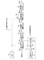
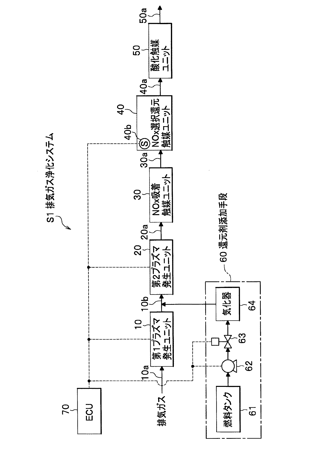
【解決手段】 排気ガスが流通する上流側から下流側に向かって、プラズマにより、第1プラズマ励起種を発生させる第1プラズマ発生ユニット10と、第2プラズマ励起種を発生させる第2プラズマ発生ユニット20と、NOx吸着触媒ユニット30と、NOx選択還元触媒ユニット40と、最下流の酸化触媒ユニット50と、還元剤添加手段60と、ECU70を備え、第1プラズマ発生ユニット10のプラズマ空間電力密度は、0.8W/cm3以上であり、第2プラズマ発生ユニット20のプラズマ空間電力密度は、0.4〜9.5W/cm3であり、粒子状物質およびNOxを連続的に浄化する排気ガス浄化システムS1である。
【選択図】 図1PROBLEM TO BE SOLVED: To provide an exhaust gas purification system and an exhaust gas purification method capable of continuously purifying particulate matter (PM) and NOx in exhaust gas.
SOLUTION: A first plasma generating unit 10 that generates a first plasma excited species by plasma and a second plasma generating unit that generates a second plasma excited species from an upstream side to a downstream side through which exhaust gas flows. 20, a NOx adsorption catalyst unit 30, a NOx selective reduction catalyst unit 40, a most downstream oxidation catalyst unit 50, a reducing agent addition means 60, and an ECU 70, and the plasma space power density of the first plasma generation unit 10 is 0.8 W / cm 3 or more, the plasma space power density of the second plasma generation unit 20 is 0.4 to 9.5 W / cm 3 , and exhaust gas that continuously purifies particulate matter and NOx. It is purification system S1.
[Selection] Figure 1
Description
本発明は、プラズマと排気ガス浄化触媒によって、自動車のディーゼルエンジンなどの内燃機関から排出される排気ガス中の粒子状物質(Particulate Matter、以下適宜PMとする)および窒素酸化物(以下、NOxとする)を浄化する排気ガス浄化システムおよび排気ガス浄化方法に関する。 The present invention relates to particulate matter (hereinafter referred to as PM) and nitrogen oxides (hereinafter referred to as NOx) in exhaust gas discharged from an internal combustion engine such as a diesel engine of an automobile by plasma and an exhaust gas purification catalyst. The present invention relates to an exhaust gas purification system and an exhaust gas purification method.
自動車のディーゼルエンジンやリーンバーンエンジンなどの内燃機関から排出される排気ガスには、PMが含まれている。このPMを低減させるため、内燃機関の下流位置に、ディーゼル微粒子フィルタ(Diesel Particulate Filter、以下DPFとする)を設ける技術が知られている。DPFは、一般に、セラミック製の多孔質フィルタからなり、これに排気ガスを通過させることによって、PMを分離、捕集し、PMを低減させて排気ガスを浄化する。
そして、DPFが所定量のPMを捕集したとき、例えばエンジンを所定に制御して排気ガス温度を上昇させ、前記捕集したPMを燃焼させることによって、DPFの再生を行っている。
PM is contained in exhaust gas discharged from an internal combustion engine such as an automobile diesel engine or lean burn engine. In order to reduce this PM, a technique of providing a diesel particulate filter (hereinafter referred to as DPF) at a downstream position of the internal combustion engine is known. The DPF is generally composed of a ceramic porous filter. By passing exhaust gas through the DPF, PM is separated and collected, and PM is reduced to purify the exhaust gas.
When the DPF collects a predetermined amount of PM, the DPF is regenerated by, for example, controlling the engine to a predetermined level to raise the exhaust gas temperature and combusting the collected PM.
また、内燃機関から排出される排気ガスには、NOxが含まれている。このNOxを低減する第1の方法としては、排気ガスに含まれる未燃焼の炭化水素(以下、HCという)、または、排気ガス中に添加された軽油、ガソリンなどのHCと、NOxとを、NOx選択還元触媒にて反応させることによって、NOxを浄化するHC−SCR(Selective Catalytic Reduction)が知られている。第2の方法としては、NOxを一時的に吸着するNOx吸着触媒を使用し、リーン(酸素過剰雰囲気)状態でNOxを吸着させ、リッチ(酸素不足雰囲気)状態で吸着したNOxを放出させると共に、HCを添加する方法が知られている。第3の方法としては、尿素(Urea)を排気ガスに添加し、触媒にて尿素からアンモニア(NH3)に変換させると共に、このアンモニアとNOxと反応させる尿素還元型選択還元触媒(Urea−SCRとも言われる)が提案されている。第4の方法としては、プラズマを利用したNOx浄化用プラズマアシスト触媒が提案されている(特許文献1参照)。
しかしながら、多孔質フィルタからなるDPFを使用すると、排気ガスの抵抗(圧力圧損)が高いため、排気ガスの流通性が低下し、その結果、エンジンパワーが十分に活かせないという問題があった。また、DPFを再生するには、前記したようにエンジンを制御しなければならない上、DPFの再生時に、DPFが1000℃を超えることもあり、DPFが溶損や破損してしまうという場合があった。 However, when a DPF made of a porous filter is used, the exhaust gas resistance (pressure pressure loss) is high, so that the exhaust gas flowability is lowered. As a result, there is a problem that the engine power cannot be fully utilized. In addition, in order to regenerate the DPF, the engine must be controlled as described above, and when the DPF is regenerated, the DPF may exceed 1000 ° C., and the DPF may be melted or damaged. It was.
一方、NOxを低減する第1の方法では、排気ガス中には未燃焼のHCが少ないという問題があった。また、第2の方法では、排気ガス中の酸素濃度を制御する必要がある上、吸入される空気量に対して過剰のHCを添加するため、燃費が大きく悪化するという問題があった。第3の方法では、尿素を貯溜するタンクや排気系への供給システム、および、尿素を供給するインフラ設備が必要な上、アンモニアが車外に放出されてしまう場合(アンモニアスリップ)もあった。さらに、第1から第4の方法では、PMを除去できなかった。 On the other hand, the first method for reducing NOx has a problem that there is little unburned HC in the exhaust gas. Further, in the second method, it is necessary to control the oxygen concentration in the exhaust gas, and excessive HC is added to the amount of intake air, so that there is a problem that fuel consumption is greatly deteriorated. In the third method, a tank for storing urea, a supply system to an exhaust system, and infrastructure equipment for supplying urea are required, and ammonia may be released outside the vehicle (ammonia slip). Furthermore, PM could not be removed by the first to fourth methods.
そこで、本発明は、排気ガス中のPMおよびNOxを連続的に浄化可能である排気ガス浄化システムおよび排気ガス浄化方法を提供することを課題とする。 Therefore, an object of the present invention is to provide an exhaust gas purification system and an exhaust gas purification method capable of continuously purifying PM and NOx in exhaust gas.
前記課題を解決するための手段として、請求項1に係る発明は、排気ガスが流通する上流側から下流側に向かって、プラズマにより、前記排気ガス中の粒子状物質およびNOxに作用するプラズマ励起種を発生させるプラズマ発生ユニットと、前記排気ガスに作用する排気ガス浄化触媒を有する排気ガス浄化触媒ユニットと、を備え、前記粒子状物質および前記NOxを連続的に浄化することを特徴とする排気ガス浄化システムである。
As means for solving the above-mentioned problem, the invention according to
このような排気ガス浄化システムによれば、プラズマ発生ユニットによって、粒子状物質およびNOxに作用するプラズマ励起種が発生する。そして、プラズマ励起種が粒子状物質を酸化し、その結果、排気ガスが浄化される。また、プラズマ励起種がNOxと作用し、NO2などに変換する。次いで、このNO2は、排気ガス浄化触媒にて還元され浄化される。このようにして、粒子状物質(PM)およびNOxを連続的に浄化することができる。 According to such an exhaust gas purification system, plasma excited species that act on particulate matter and NOx are generated by the plasma generation unit. The plasma excited species oxidizes the particulate matter, and as a result, the exhaust gas is purified. In addition, the plasma excited species interacts with NOx and is converted to NO 2 or the like. Next, this NO 2 is reduced and purified by the exhaust gas purification catalyst. In this way, particulate matter (PM) and NOx can be purified continuously.
請求項2に係る発明は、前記プラズマ発生ユニットは、前記粒子状物質に主として作用する第1プラズマ励起種の発生率が上流側で高く、前記NOxに主として作用する第2プラズマ励起種の発生率が下流側で高くなるように構成されたことを特徴とする請求項1に記載の排気ガス浄化システムである。
In the invention according to
このような排気ガス浄化システムによれば、第1プラズマ励起種がプラズマ発生ユニットの上流側において発生しやすくなる。そして、第1プラズマ励起種が粒子状物質と作用し、排気ガスが浄化される。すなわち、プラズマ発生ユニットの上流側において、粒子状物質が浄化されやすくなる。したがって、プラズマを発生させる電極などに、粒子状物質が付着しにくくなり、プラズマ発生ユニットの耐久性が高くなる。
一方、第2プラズマ励起種はプラズマ発生ユニットの下流側で発生しやすくなる。そして、第2プラズマ励起種がNOxと作用してNO2などに変換し、NO2は排気ガス浄化触媒により浄化される。
なお、このように第1プラズマ励起種の発生率が上流側で、第2プラズマ励起種の発生率が下流側で高くなるように構成するためには、例えば、プラズマを発生させる電極の数、大きさ、間隔、印加する電圧などを、上流側から下流側に流通する排気ガスの流れに対して、連続的、段階的に変化させて、プラズマ空間密度が、下流に向かうにつれ低くなるように構成するなどが挙げられる。
According to such an exhaust gas purification system, the first plasma excited species is easily generated on the upstream side of the plasma generation unit. Then, the first plasma excited species acts on the particulate matter, and the exhaust gas is purified. That is, the particulate matter is easily purified on the upstream side of the plasma generation unit. Therefore, the particulate matter is less likely to adhere to an electrode that generates plasma, and the durability of the plasma generation unit is increased.
On the other hand, the second plasma excited species is likely to be generated on the downstream side of the plasma generation unit. Then, the second plasma excited species acts on NOx to convert to NO 2 or the like, and NO 2 is purified by the exhaust gas purification catalyst.
In order to configure the generation rate of the first plasma excitation species on the upstream side and the generation rate of the second plasma excitation species on the downstream side in this way, for example, the number of electrodes for generating plasma, The size, spacing, applied voltage, etc., are continuously and stepwise changed with respect to the flow of exhaust gas flowing from the upstream side to the downstream side so that the plasma spatial density becomes lower as it goes downstream. For example.
請求項3に係る発明は、前記プラズマ発生ユニットは、前記第1プラズマ励起種を発生させる上流側の第1プラズマ発生ユニットと、前記第2プラズマ励起種を発生させる下流側の第2プラズマ発生ユニットと、を備えたことを特徴とする請求項2に記載の排気ガス浄化システムである。
According to a third aspect of the present invention, the plasma generation unit includes an upstream first plasma generation unit that generates the first plasma excitation species and a downstream second plasma generation unit that generates the second plasma excitation species. And an exhaust gas purification system according to
このような排気ガス浄化システムによれば、上流側の第1プラズマ発生ユニットにより第1プラズマ励起種を、下流側の第2プラズマ励起種により第2プラズマ励起種を、別々により確実に発生させることができる。 According to such an exhaust gas purification system, the first plasma excited species is generated by the upstream first plasma generating unit, and the second plasma excited species is reliably generated separately by the downstream second plasma excited species. Can do.
請求項4に係る発明は、前記第1プラズマ発生ユニットのプラズマ空間電力密度は、0.8W/cm3以上であり、前記第2プラズマ発生ユニットのプラズマ空間電力密度は、0.4〜9.5W/cm3であることを特徴とする請求項3に記載の排気ガス浄化システムである。
In the invention according to
このような排気ガス浄化システムによれば、第1プラズマ発生ユニットで発生する第1プラズマ励起種によりPMを高い浄化率で浄化し、第2プラズマ発生ユニットで発生する第2プラズマ励起種によりNOxをNO2などに高い変換率で変換することができる。
また、一般に、NOxをNO2などに変換するには、PMの浄化に対して、高いプラズマ空間電力密度を必要としないため、第2プラズマ発生ユニットにおけるプラズマ空間電力密度が、第1プラズマ発生ユニットのプラズマ空間電力密度以下に設定された場合には、PMが浄化された排気ガスが流通する第2プラズマ発生ユニットにおいて、プラズマを発生させるために、無駄なく電力を消費することができる。
According to such an exhaust gas purification system, PM is purified at a high purification rate by the first plasma excited species generated in the first plasma generating unit, and NOx is purified by the second plasma excited species generated in the second plasma generating unit. Conversion to NO 2 or the like can be performed at a high conversion rate.
In general, in order to convert NOx to NO 2 or the like, a high plasma space power density is not required for PM purification, so that the plasma space power density in the second plasma generation unit is the first plasma generation unit. When the plasma space power density is set to be equal to or lower than the plasma space power density, power can be consumed without waste in order to generate plasma in the second plasma generation unit in which the exhaust gas from which PM has been purified flows.
請求項5に係る発明は、前記排気ガス浄化触媒は、NOx選択還元触媒であることを特徴とする請求項3または請求項4に記載の排気ガス浄化システムである。
The invention according to
このような排気ガス浄化システムによれば、NOx選択還元触媒によって、NO2などのNOxを良好に分解することで排気ガスを浄化することができる。 According to such an exhaust gas purification system, it can be the NOx selective reduction catalyst, for purifying the exhaust gas by well decompose NOx such as NO 2.
請求項6に係る発明は、前記第2プラズマ発生ユニットと前記NOx選択還元触媒を有する前記排気ガス浄化触媒ユニットとの間に、NOx吸着触媒を有するNOx吸着触媒ユニットを、さらに備えたことを特徴とする請求項5に記載の排気ガス浄化システムである。
The invention according to
このような排気ガス浄化システムによれば、NOx選択還元触媒の活性が低く、NOxを好適に分解できない場合、NOx吸着触媒によってNOxを一時的に吸着することができる。 According to such an exhaust gas purification system, when the activity of the NOx selective reduction catalyst is low and NOx cannot be suitably decomposed, NOx can be temporarily adsorbed by the NOx adsorption catalyst.
請求項7に係る発明は、前記NOx選択還元触媒の温度を検出する温度センサをさらに備え、前記NOx選択還元触媒の温度が、所定の活性温度以上のとき、前記第2プラズマ発生ユニットを作動させることを特徴とする請求項5または請求項6に記載の排気ガス浄化システムである。
The invention according to
このような排気ガス浄化システムによれば、温度センサによってNOx選択触媒の活性状況を監視し、NOx選択還元触媒が活性を有するときにのみ、第2プラズマ発生ユニットを作動させて、第2プラズマ励起種を発生させてNO2などを生成可能となり、第2プラズマ発生ユニットにおいて無駄なく電力を消費することができる。 According to such an exhaust gas purification system, the activation state of the NOx selective catalyst is monitored by the temperature sensor, and the second plasma generation unit is operated only when the NOx selective reduction catalyst is active, and the second plasma excitation is performed. The seeds can be generated to generate NO 2 and the like, and power can be consumed without waste in the second plasma generation unit.
請求項8に係る発明は、前記NOx選択還元触媒を有する前記排気ガス浄化触媒ユニットの上流側で、前記排気ガスに還元剤を添加する還元剤添加手段をさらに備え、前記NOx選択還元触媒が前記活性温度以上のとき、前記還元剤を添加することを特徴とする請求項7に記載の排気ガス浄化システムである。
The invention according to
このような排気ガス浄化システムによれば、NOx選択還元触媒が所定活性温度以上のときのみに還元剤を添加し、添加した還元剤とNOxとをNOx選択還元触媒にて作用させ、排気ガスを浄化することができ、無駄なく還元剤を添加することができる。
また、還元剤添加手段により、第2プラズマ発生ユニットの上流側で、還元剤を添加可能に構成し、例えば、還元剤としてHCを使用した場合には、第2プラズマ発生ユニットによる第2プラズマ励起種とHCとが作用して、アルデヒド種、含窒素酸化物炭化水素など反応性の高い物質が生成し、この物質は、NOx選択還元触媒にてNOxを高効率で分解するため、さらに好適に排気ガスを浄化することができる。
According to such an exhaust gas purification system, the reducing agent is added only when the NOx selective reduction catalyst is equal to or higher than the predetermined activation temperature, the added reducing agent and NOx are allowed to act on the NOx selective reduction catalyst, and the exhaust gas is discharged. It can be purified and the reducing agent can be added without waste.
Further, the reducing agent addition means is configured to be able to add the reducing agent upstream of the second plasma generating unit. For example, when HC is used as the reducing agent, the second plasma generating unit excites the second plasma. Species and HC act to produce highly reactive substances such as aldehyde seeds and nitrogen-containing oxide hydrocarbons. This substance decomposes NOx with high efficiency using a NOx selective reduction catalyst, and is more suitable. Exhaust gas can be purified.
請求項9に係る発明は、前記NOx選択還元触媒を有する前記排気ガス浄化触媒ユニットの下流側に、酸化触媒を有する酸化触媒ユニットを、さらに備えたことを特徴とする請求項5から請求項8のいずれか1項に記載の排気ガス浄化システムである。
The invention according to
このような排気ガス浄化システムによれば、酸化触媒によって、排気ガスをさらに酸化浄化することができる。 According to such an exhaust gas purification system, the exhaust gas can be further oxidized and purified by the oxidation catalyst.
請求項10に係る発明は、粒子状物質およびNOxを含む排気ガスを連続的に浄化する排気ガス浄化方法であって、プラズマにより、前記排気ガス中の粒子状物質およびNOxに作用するプラズマ励起種を発生させる第1工程と、排気ガス浄化触媒により、排気ガスを浄化する第2工程と、を有することを特徴とする排気ガス浄化方法である。
The invention according to
このような排気ガス浄化方法によれば、プラズマにより、粒子状物質およびNOxに作用するプラズマ励起種が発生する(第1工程)。この粒子状物質は、プラズマ励起種と作用し、その結果排気ガスは浄化される。一方、NOxは、プラズマ励起種と作用しNO2などに変換される。次いで、このNO2は、排気ガス浄化触媒にて還元され浄化される(第2工程)。このように粒子状物質(PM)およびNOxを連続的に浄化することができる。 According to such an exhaust gas purification method, plasma excited species that act on particulate matter and NOx are generated by the plasma (first step). This particulate matter acts with plasma excited species, and as a result, the exhaust gas is purified. On the other hand, NOx acts on plasma excited species and is converted to NO 2 or the like. Next, this NO 2 is reduced and purified by the exhaust gas purification catalyst (second step). In this way, particulate matter (PM) and NOx can be purified continuously.
請求項11に係る発明は、前記第1工程は、前記粒子状物質に主として作用する第1プラズマ励起種を発生させる第1A工程と、前記NOxに主として作用する第2プラズマ励起種を発生させる第1B工程と、を有することを特徴とする請求項10に記載の排気ガス浄化方法である。
According to an eleventh aspect of the present invention, in the first step, the first step A generates a first plasma excited species mainly acting on the particulate matter, and the second step generates a second plasma excited species mainly acting on the NOx. The exhaust gas purification method according to
このような排気ガス浄化方法によれば、第1A工程において、第1プラズマ励起種を発生させて、粒状物質を浄化することができる。そして、第1B工程において、第2プラズマ励起種を発生させてNOxに作用させて、NO2などの反応性の高い物質を生成することができる。 According to such an exhaust gas purification method, the particulate matter can be purified by generating the first plasma excited species in the first step A. In the first step B, the second plasma excited species can be generated and act on NOx to generate a highly reactive substance such as NO 2 .
本発明によれば、排気ガス中のPMおよびNOxを連続的に浄化可能である排気ガス浄化システムおよび排気ガス浄化方法を提供することができる。
すなわち、請求項1および請求項10に係る発明によれば、プラズマ励起種により、PMおよびNOxを連続的に浄化することができる。
請求項2に係る発明によれば、粒子状物質がプラズマを発生させる電極に付着しにくくなり、耐久性が高くなる。
請求項3および請求項11に係る発明によれば、第1プラズマ励起種と第2プラズマ励起種を、別々により確実に発生させることができる。
請求項4に係る発明によれば、PMを高い浄化率で浄化し、NOxをNO2などに高い変換率で変換することができる。
請求項5に係る発明によれば、NOx選択還元触媒により、排気ガスを浄化することができる。
請求項6に係る発明によれば、NOxを一時的に吸着することができる。
請求項7に係る発明によれば、電力を節約し、第2プラズマ発生ユニットを無駄なく作動させることができる。
請求項8に係る発明によれば、無駄なく還元剤を添加することができる。
請求項9に係る発明によれば、酸化触媒によって、排気ガスをさらに酸化浄化することができる。
According to the present invention, it is possible to provide an exhaust gas purification system and an exhaust gas purification method capable of continuously purifying PM and NOx in exhaust gas.
That is, according to the
According to the second aspect of the present invention, the particulate matter hardly adheres to the electrode that generates plasma, and the durability is increased.
According to the
According to the fourth aspect of the present invention, PM can be purified at a high purification rate, and NOx can be converted to NO 2 or the like at a high conversion rate.
According to the invention of
According to the invention which concerns on
According to the invention of
According to the invention which concerns on
According to the ninth aspect of the invention, the exhaust gas can be further oxidized and purified by the oxidation catalyst.
次に、本発明の一実施形態について、図1および図2を参照して詳細に説明する。
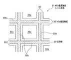
参照する図面において、図1は、本実施形態に係る排気ガス浄化システムの全体構成図である。図2は、図1に示すNOx吸着触媒ユニットに内蔵されたNOx吸着触媒ユニット本体の断面図である。
Next, an embodiment of the present invention will be described in detail with reference to FIG. 1 and FIG.
In the drawings to be referred to, FIG. 1 is an overall configuration diagram of an exhaust gas purification system according to the present embodiment. FIG. 2 is a cross-sectional view of the NOx adsorption catalyst unit main body built in the NOx adsorption catalyst unit shown in FIG.
<排気ガス浄化システムの構成>
図1に示すように、本実施形態に係る排気ガス浄化システムS1は、エンジン(内燃機関)を有する車両に搭載されており、エンジンから排出される排気ガス中のPMおよびNOxを連続的に浄化するシステムである。
排気ガス浄化システムS1は、主として、排気ガス発生側(上流側)から排気側(下流側)に向かって、第1プラズマ発生ユニット10と、第2プラズマ発生ユニット20と、NOx吸着触媒ユニット30と、NOx選択還元触媒ユニット40(排気ガス浄化触媒ユニット)と、酸化触媒ユニット50とを備え、さらに、第1プラズマ発生ユニット10と第2プラズマ発生ユニット20の間(第2プラズマ発生ユニット上流側)で排気ガスに還元剤であるHCを添加する還元剤添加手段60と、制御ユニット70(以下、ECUという)を備えて構成されている。
<Configuration of exhaust gas purification system>
As shown in FIG. 1, the exhaust gas purification system S1 according to this embodiment is mounted on a vehicle having an engine (internal combustion engine), and continuously purifies PM and NOx in exhaust gas discharged from the engine. System.
The exhaust gas purification system S1 mainly includes a first
[第1プラズマ発生ユニット]
第1プラズマ発生ユニット10は、前記エンジンから排出された排気ガスが流通する配管10aの下流側に接続している。また、第1プラズマ発生ユニット10は、ECU70と電気的に接続しており、ECU70は第1プラズマ発生ユニット10を作動を制御可能となっている。
第1プラズマ発生ユニット10は、プラズマを発生可能な電極板を内蔵し、プラズマにより、主としてPMに作用するO(酸素原子)励起種、OH(ハイドロオキサイド)励起種、OOH(パーハイドロオキサイド)励起種、などの第1プラズマ励起種を生成させるものである。詳細には、例えば、所定間隔に配置された電極板間に所定電圧を印加することでプラズマが発生し、これにより、電極板から飛び出した電子が、排気ガス中の分子に衝突することで、主として前記第1プラズマ励起種を生成可能となっている。そして、この第1プラズマ励起種は、高い酸化力を有するため、逐次、排気ガス中のPMと接触することによって、PMを酸化し浄化可能となっている。ここで、プラズマを発生させる形式は、本発明では特に限定はないが、例えば、コロナ放電形式、パルス放電方式、バリア放電方式などを採用することができる。
[First plasma generation unit]
The first
The first
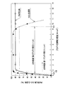
第1プラズマ発生ユニット10におけるプラズマ空間電力密度は、0.8W/cm3以上に設定されている。これは、後記する実施例で説明するように、プラズマ空間電力密度が0.8W/cm3以上において、PMが80%以上浄化されたからである(図5参照)。
なお、プラズマ空間電力密度とは、プラズマを発生するにときに消費された電力を、プラズマが発生する空間の体積(以下、プラズマ空間体積)で除算した値である。プラズマ空間Sとは、例えば、後記実施例のように、プラズマを発生させる電極板112、112…を所定間隔で平行に配置された場合には(図4参照)、電極板112、112…間の空間の体積が相当する。そして、プラズマ空間電力密度が高いほど、プラズマ中に高いエネルギーを有する電子が存在していることを意味し、第1プラズマ励起種を効率的に生成可能であることを意味する。
The plasma space power density in the first
The plasma space power density is a value obtained by dividing the power consumed when generating plasma by the volume of the space where plasma is generated (hereinafter referred to as plasma space volume). The plasma space S is, for example, between the
[第2プラズマ発生ユニット]
第2プラズマ発生ユニット20は、第1プラズマ発生ユニット10の後段に配管10bを介して接続している。また、第2プラズマ発生ユニット20は、ECU70と電気的に接続しており、ECU70は第2プラズマ発生ユニット20の作動を制御可能となっている。
第2プラズマ発生ユニット20は、プラズマにより、主として、排気ガス中のNOx、還元剤添加手段60から添加されたHCに作用するO(酸素原子)励起種、OH(ハイドロオキサイド)励起種、OOH(パーハイドロオキサイド)励起種、NOx励起種などの第2プラズマ励起種を生成させるものである。これら第2プラズマ励起種のうち、主として、O励起種がO2(酸素)と反応し、O3(オゾン)が生成する。O3は、排気ガス中のNOxと直ちに反応し、NO2が生成可能となっている。また、O3は、燃料添加手段から添加されたHCと反応して、アセトアルデヒド(CH3CHO)などのアルデヒド種や、プラズマ中に存在するNOx励起種と反応して窒素酸化物を含む炭化水素(以下、含窒素酸化物炭化水素という)を生成可能となっている。
[Second plasma generation unit]
The second
The second
さらに、第2プラズマ発生ユニット20におけるプラズマ空間電力密度は、0.4〜9.5W/cm3の範囲内に設定されている。これは、後記する実施例で説明するように、プラズマ空間電力密度が0.4〜9.5W/cm3の範囲内で、第2プラズマ励起種と反応しNOxが消費されたことに基づくNO2の生成率が80%以上となるからである(図5参照)。
Furthermore, the plasma space power density in the second
このように本実施形態に係る排気ガス浄化システムS1は、プラズマ発生ユニットとして、第1プラズマ発生ユニット10と、第2プラズマ発生ユニット20とを備えたことによって、これらを独立して制御可能となり、第1プラズマ発生ユニット10によってPMを浄化し、第2プラズマ発生ユニット20によって、反応性の高いNO2などを生成可能となっている。
As described above, the exhaust gas purification system S1 according to the present embodiment includes the first
[NOx吸着触媒ユニット]
NOx吸着触媒ユニット30は、第2プラズマ発生ユニット20の後段に配管20aを介して接続されており、所定温度(NOx選択還元触媒の活性温度)以下ではNOxを一時的に吸着し、前記所定温度以上では吸着したNOxを放出するNOx吸着触媒を有している。
さらに説明すると、NOx吸着触媒ユニット30は、その内部に、排気ガスが流通する複数の細孔32aを有する支持体32を含むNOx吸着触媒ユニット本体31を備えている(図2参照)。NOx吸着触媒ユニット本体31は、支持体32と、支持体32の複数の細孔32aを取り囲む内壁面32bを覆うように層状で形成されたNOx吸着触媒33を有している。ここで、NOx吸着触媒33は、後記実施例で記載するように、支持体32をスラリ状のNOx吸着触媒スラリに含浸して製造されるため、ウォッシュコート(層)、と称されることもある。
[NOx adsorption catalyst unit]
The NOx
More specifically, the NOx
支持体32の形状は、排気ガスが流通する空間を有していれば、本発明では特に限定されないが、本実施形態では図2に示すように、排気ガスとの接触面積および機械的強度を考慮し、複数の細孔32aが形成されたハニカム状のものを使用している。また、支持体32は、耐熱性を有する材料から形成されることが好ましく、このような材料としては、例えば、コージエライト、ムライト、シリコンカーバイド(SiC)などの多孔質担体(セラミックス)や、ステンレスなどのメタルが挙げられる。
また、NOx吸着触媒33としては、例えば、触媒活性物質として、アルカリ金属やアルカリ土類金属を担持した多孔質担体を使用することができる。多孔質担体としては、アルミナ、シリカ、シリカアルミナ、ゼオライト等が挙げられる。
The shape of the support 32 is not particularly limited in the present invention as long as it has a space through which exhaust gas flows. In this embodiment, as shown in FIG. 2, the contact area with the exhaust gas and the mechanical strength are increased. Considering this, a honeycomb-shaped one having a plurality of
Further, as the
[NOx選択還元触媒ユニット]
図1に戻って説明を続ける。
NOx選択還元触媒ユニット40は、NOx吸着触媒ユニット30の後段に配管30aを介して接続されており、NOxを選択的に浄化するNOx選択還元触媒(排気ガス浄化触媒)を有している。
さらに説明すると、NOx選択還元触媒ユニット40は、NOx吸着触媒ユニット30と同様の構造であり、その内部にハニカム状のNOx選択還元触媒ユニット本体を内蔵している。このNOx選択還元触媒ユニット本体は、前記NOx吸着触媒に代えてNOx選択還元触媒を有している。NOx選択還元触媒は、例えば、触媒活性物質として、銀(Ag)を担持した多孔質担体を使用することができる。多孔質担体としては、アルミナ、シリカ、シリカアルミナ、ゼオライト等が挙げられる。また、銀に代えて酸点を有するゼオライト(例えば、モデルナイト)がアルミナに担持されたものを使用することができる。
また、NOx選択還元触媒ユニット40には、前記NOx選択還元触媒の温度を検出する温度センサ40bが内蔵されており、この温度センサ40bは電気的にECU70と接続している。したがって、ECU70は、温度センサ40bを介してNOx選択還元触媒の温度を監視することによって、NOx選択還元触媒の活性状態を把握可能となっている。
[NOx selective reduction catalyst unit]
Returning to FIG. 1, the description will be continued.
The NOx selective
More specifically, the NOx selective
The NOx selective
[酸化触媒ユニット]
酸化触媒ユニット50は、NOx選択還元触媒ユニット40の後段に配管40aを介して接続されており、排気ガスを補助的に酸化浄化する酸化触媒を内蔵する。そして、酸化触媒ユニット50の下流側には、排気用の配管50aが設けられている。
さらに説明すると、酸化触媒ユニット50は、NOx吸着触媒ユニット30と同様の構造であり、その内部にハニカム状の酸化触媒ユニット本体を有している。この酸化触媒ユニット本体は、前記NOx吸着触媒に代えて、酸化触媒を有している。酸化触媒は、前記セシウム(Cs)に代えて、触媒活性物質として、例えば、白金(Pt)がベースのアルミナに担持されたものを使用することができる。
[Oxidation catalyst unit]
The
More specifically, the
[還元剤添加手段]
還元剤添加手段60は、第2プラズマ発生ユニット20の直上流側で、排気ガスに還元剤としてHCを添加する手段であり、本実施形態ではHCとして軽油、ガソリンなどの燃料を使用している。還元剤添加手段60は、下流側に向かって、燃料タンク61、燃料ポンプ62、流量調整弁63、気化器64と、これら機器を接続させる配管を備えて構成されている。燃料ポンプ62および流量調整弁63は、ECU70と電気的に接続しており、ECU70により制御可能となっている。また、気化器64自体は流通する排気ガスの熱により、所定に加熱され、燃料を気化可能となっている。したがって、ECU70により、燃料ポンプ62を適宜作動させ、流量調整弁63を所定の開度に制御することで、所定量のHCを排気ガスに添加可能となっている。
[Reducing agent addition means]
The reducing agent adding means 60 is means for adding HC as a reducing agent to the exhaust gas immediately upstream of the second
[ECU70]
ECU70は、排気ガス浄化システムの動作を制御するものであり、CPU、ROM、I/Oなどから構成されている。ECU70は、第1プラズマ発生ユニット10と、第2プラズマ発生ユニット20と、温度センサ40bと、燃料ポンプ62と、流量調整弁63と電気的に接続している。なお、ECU70の機能は、次の動作の記載において詳細に説明する。
[ECU 70]
The
<排気ガス浄化システムの動作>
続いて、排気ガス浄化システムS1の動作とともに、本実施形態に係る排気ガス浄化方法について、図1を参照して説明する。
<Operation of exhaust gas purification system>
Next, the exhaust gas purification method according to the present embodiment, together with the operation of the exhaust gas purification system S1, will be described with reference to FIG.
作動するエンジン(図示しない)から排出された排気ガスが、配管10aを経由して、排気ガス浄化システムS1の上流側から導入される。排気ガスの導入にともなって、ECU70は、第1プラズマ発生ユニット10を、プラズマ空間電力密度0.8W/cm3以上にて作動させる。そうすると、第1プラズマ発生ユニット10では、O(酸素原子)励起種、OH(ハイドロオキサイド)励起種、OOH(パーハイドロオキサイド)励起種、などの第1プラズマ励起種が生成する。この第1プラズマ励起種(特にO励起種)は、排気ガス中のPMに作用し、PMを酸化浄化する。なお、この工程が特許請求の範囲における第1A工程に相当する。
Exhaust gas discharged from an operating engine (not shown) is introduced from the upstream side of the exhaust gas purification system S1 via the
そして、ECU70は、燃料ポンプ62および流量調整弁63を所定に制御し、所定量のHCを排気ガスに添加する。なお、ECU70は、温度センサ40bにより検出されたNOx選択還元触媒の温度が所定の活性温度より低い場合、HCを添加しない。これにより、無駄なくHCを添加可能であるため、燃費が大幅に悪化することはない。
The
そして、ECU70は、第2プラズマ発生ユニット20を、プラズマ空間電力密度0.4〜9.5W/cm3にて作動させる。そうすると、第2プラズマ発生ユニット20では、O励起種、OH励起種、OOH励起種、NOx励起種などの第2プラズマ励起種が生成する。
このうち、O励起種は酸素(O2)と反応し、オゾン(O3)が生成する。オゾン(O3)は、排気ガス中のNOxと直ちに反応し、NO2が生成する。また、O3は添加されたHCと反応して、アセトアルデヒド(CH3CHO)などのアルデヒド種や、NOx励起種と反応して含窒素酸化物炭化水素が生成する。なお、この工程が特許請求の範囲における第1B工程に相当する。
一方、ECU70は、エンジンの作動直後など排気ガスの温度が低く、温度センサ40bにより検出されたNOx選択還元触媒の温度が所定の活性温度より低い場合、第2プラズマ発生ユニット20を作動させない。これにより電力を節約することができる。
Then, the
Among these, O excited species react with oxygen (O 2 ) to generate ozone (O 3 ). Ozone (O 3 ) reacts immediately with NOx in the exhaust gas to produce NO 2 . Further, O 3 reacts with the added HC and reacts with aldehyde species such as acetaldehyde (CH 3 CHO) or NOx excited species to generate nitrogen-containing oxide hydrocarbons. This process corresponds to the 1B process in the claims.
On the other hand, the
そして、NOx吸着触媒ユニット30は、前記エンジンの作動直後などNOx選択還元触媒の温度が低いときは、排気ガス中のNOxを一時的に吸着する。
一方、排気ガスの温度が上昇し、NOx選択還元触媒の温度も上昇し、所定の触媒活性を有するとき、吸着したNOxを放出する。
The NOx
On the other hand, when the temperature of the exhaust gas rises and the temperature of the NOx selective reduction catalyst also rises and has a predetermined catalytic activity, the adsorbed NOx is released.
次いで、NOx選択還元触媒ユニット40では、NOx選択還元触媒上にて、アルデヒド種および含窒素酸化物炭化水素によるNO2の還元反応が生じる。そして、この反応による反応熱を基にして、排気ガスに含まれるNOや他のHC種との反応も開始することになり、全体として低温からNOxを高い浄化率で浄化することができる。
なお、この工程が特許請求の範囲における第2工程に相当する。
Next, in the NOx selective
This step corresponds to the second step in the claims.
その後、酸化触媒ユニット50により、排気ガスは補助的に酸化浄化された後、配管50aを介して、外部に排出される。
Thereafter, the exhaust gas is supplementarily oxidized and purified by the
このように本実施形態に係る排気ガス浄化システムS1によれば、排気ガス中のPMおよびNOxを連続的に浄化することができる。 As described above, according to the exhaust gas purification system S1 according to this embodiment, PM and NOx in the exhaust gas can be continuously purified.
以上、本発明の好適な実施形態について一例を説明したが、本発明は前記実施形態に限定されず、本発明の趣旨を逸脱しない範囲で、例えば以下のような変更をすることができる。 As mentioned above, although an example was described about suitable embodiment of this invention, this invention is not limited to the said embodiment, For example, the following changes can be made in the range which does not deviate from the meaning of this invention.
前記した実施形態では、自動車のエンジンから排出される排気ガス中のPMおよびNOxを浄化するとしたが、排気ガス浄化システムS1の適用はこれに限定されず、その他に例えば、工場などから排出される煤煙中のPMおよびNOxを除去するために適用してもよい。 In the above-described embodiment, PM and NOx in exhaust gas discharged from the engine of the automobile are purified. However, the application of the exhaust gas purification system S1 is not limited to this, and the exhaust gas is discharged from, for example, a factory or the like. It may be applied to remove PM and NOx in soot.
前記した実施形態では、排気ガス浄化システムS1は、第1プラズマ発生ユニット10と、第2プラズマ発生ユニット20とを別々に備えて構成されたとしたが、これに限定されず一体的に構成されてもよい。
In the above-described embodiment, the exhaust gas purification system S1 is configured to include the first
その他、1つのプラズマ発生ユニットの内部に、プラズマを発生させる電極の数、間隔、配置、電極に印加する電圧を、下流側に向かって連続的、段階的に設定し、第1プラズマ励起種の発生率が上流側で、第2プラズマ励起種の発生率が下流側で、高くなるように設定してもよい。 In addition, the number of electrodes for generating plasma, the interval, the arrangement, and the voltage applied to the electrodes are set continuously and stepwise toward the downstream side in one plasma generation unit, and the first plasma excitation species The generation rate may be set to be higher on the upstream side, and the generation rate of the second plasma excited species may be higher on the downstream side.
以下、実施例に基づいて、本発明をさらに具体的に説明する。 Hereinafter, based on an Example, this invention is demonstrated further more concretely.
(1)排気ガス浄化システム
(1−1)排気ガス浄化システムの構成
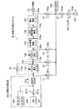
まず、実施例において使用した排気ガス浄化システムS2の構成について、図3を参照して説明する。
排気ガス浄化システムS2は、最上流側の排気ガス発生部200で発生した排気ガスを浄化するシステムであり、下流側に向かって、主として、第1プラズマ発生ユニット110と、第2プラズマ発生ユニット120と、NOx吸着触媒ユニット130と、NOx選択還元触媒ユニット140と、酸化触媒ユニット150と、排気ガス量を測定する最下位置の流量計161と、これら機器を接続させる配管110b、120a、130a、140a、150aを備えており、図示しない還元剤添加手段により、第1プラズマ発生ユニット110と第2プラズマ発生ユニット120の間で、排気ガスにHC(還元剤)を添加可能となっている。HCとしては、ノルマルデカン(n−C10H22)を使用した。また、第1プラズマ発生ユニット110を迂回するように、開閉弁V6を有する配管110dが設けられている。
(1) Exhaust Gas Purification System (1-1) Configuration of Exhaust Gas Purification System First, the configuration of the exhaust gas purification system S2 used in the examples will be described with reference to FIG.
The exhaust gas purification system S2 is a system that purifies the exhaust gas generated by the exhaust gas generation unit 200 on the most upstream side, and mainly the first
(1−2)プラズマ発生ユニット
次に、プラズマ発生ユニットについて説明する。
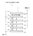
第1プラズマ発生ユニット110は、その内部に、図4に示す第1プラズマ発生ユニット本体111を内蔵している。なお、図4は第1プラズマ発生ユニット本体の構成を部分的に示す断面図である。
第1プラズマ発生ユニット本体111は、片面が誘電体113で被覆された金属製の電極板112、112…を同一の向きにて所定間隔(d1)で配置し、1枚おきに電極板112、112…を高電圧入力側に接続し、高電圧入力側に接続しない電極板112、112…をアース側(GND)に接続し、誘電体113、113…と、前記所定間隔(d1)を隔てて対向した電極板112、112…との間をプラズマが発生するプラズマ空間Sとなるように構成した。電極板112、112…は、SUS316で形成し、厚さは1.0mm、大きさは20mm×50mmとした。一方、誘電体113、113…は、アルミナ(Al2O3)で形成し、厚さは0.5mmとした。そして、第1プラズマ発生ユニット110では、前記所定間隔d1(プラズマ空間Sの厚み)を0.5mmに設定し、プラズマ空間Sが10層となるように、電極板112、112…を配置した。したがって、第1プラズマ発生ユニット110において、1層あたりのプラズマ空間Sの体積は0.5cm3となり、プラズマ空間Sの総体積は5.0cm3となる(後記する表3参照)。
(1-2) Plasma Generation Unit Next, the plasma generation unit will be described.
The first
The first plasma generation unit main body 111 has
一方、第2プラズマ発生ユニット120は、第1プラズマ発生ユニット110と同様の構成であるが、前記所定間隔d1を1.5mmに設定し、プラズマ空間Sが3層となるように電極板112、112…を配置した。したがって、第2プラズマ発生ユニット120において、1層あたりのプラズマ空間Sの体積は1.5cm3となり、プラズマ空間Sの総体積は4.5cm3となる(後記する表3参照)。
On the other hand, the second
(1−3)排気ガス発生部
図3に戻って排気ガス発生部200について説明する。
排気ガス発生部200は、主として、次の表1に示す仕様のディーゼルエンジン201と、高圧の窒素が貯蔵されたN2タンク202と、高圧の酸素が貯蔵されたO2タンク203と、ヒータ204を備えて構成されている。ディーゼルエンジン201は、流量調整弁201bを有する配管201aを介して、第1プラズマ発生ユニット110に接続している。N2タンク202、O2タンク203は、流量調整弁201bの下流側で配管201aに接続しており、ディーゼルエンジン201で発生した排気ガスに、所定量の窒素、酸素を添加可能となっている。ヒータ204は、排気ガス浄化システムS2に導入される排気ガスを所定温度に加熱可能となるように、配管201aの近傍に設けられている。
(1-3) Exhaust Gas Generation Unit Returning to FIG. 3, the exhaust gas generation unit 200 will be described.
The exhaust gas generation unit 200 mainly includes a
また、実施例では、排気ガスが次の表2の成分割合となるように、窒素、酸素を添加した。なお、表2に示す成分割合は、排気ガスが25℃、1013hPa(1気圧)のときの値である。 In the examples, nitrogen and oxygen were added so that the exhaust gas had the component ratios shown in Table 2 below. The component ratios shown in Table 2 are values when the exhaust gas is 25 ° C. and 1013 hPa (1 atm).
(1−4)排気ガス分析部
次に、このように構成された排気ガス浄化システムS2を流通する排気ガスを分析する排気ガス分析部について説明する。
まず、ヒータ204の下流側において、配管201aから分岐するように、開閉弁V1を有する配管201cが設けられている。配管201cは、その下流側でガス分析計162(堀場製作所社製、MEXA-4300FT)と接続している。したがって、開閉弁V1を適宜開放することで、第1プラズマ発生ユニット110に導入される排気ガスの組成を分析可能となっている。なお、NOx濃度は、NOとNO2の和として算出した。
(1-4) Exhaust Gas Analysis Unit Next, an exhaust gas analysis unit that analyzes the exhaust gas flowing through the thus configured exhaust gas purification system S2 will be described.
First, on the downstream side of the
また、第1プラズマ発生ユニット110と第2プラズマ発生ユニット120とを接続する配管110bには開閉弁V2を有する配管110cが、第2プラズマ発生ユニット120とNOx吸着触媒ユニット130を接続する配管120aには開閉弁V3を有する配管120cが、酸化触媒ユニット150と流量計161とを接続する配管150aには開閉弁V4を有する配管150cが、それぞれ分岐するように設けられており、配管110c、配管120c、配管150cは、その下流で配管201cに合流している。したがって、開閉弁V2、V3、V4を適宜開閉させることで、所定位置の排気ガスをサンプリングし、ガス分析計162により排気ガスの組成を分析可能となっている。
A pipe 110c having an on-off valve V2 is connected to the
さらに、配管201cに分岐するように、開閉弁V5を有する配管163aが設けられている。この配管163aの下流側に順に、フィルタ163、配管163b、吸引ポンプ164が接続している。そして、開閉弁V5を開放した状態で吸引ポンプ164を作動させることで配管201cを流通するガスを吸引し、このガス中のPMをフィルタ163で捕集することによって、捕集前後の質量差に基づく質量法により、排気ガス中のPM質量を測定可能となっている。なお、フィルタ163は、0.3μmメッシュのものを使用した。
Further, a
(1−5)各触媒ユニットの製造
次に、NOx吸着触媒ユニット130、NOx選択還元触媒ユニット140、酸化触媒ユニット150の製造方法について説明する。
(1-5) Manufacturing of each catalyst unit Next, a manufacturing method of the NOx
(1−5−1)NOx吸着触媒ユニット本体の製造
NOx吸着触媒としては、Cs−USY型ゼオライト触媒粉末を使用した。その調製方法は次の通りである。
Na−USY型ゼオライト粉末100g、硝酸セシウム257g、イオン交換水1000gをセパラブルフラスコに入れ、90℃に加熱しながら14時間撹拌し、濾過、純水洗浄した後、乾燥炉にて150℃で2時間、さらにマッフル炉にて400℃で12時間乾燥して、粉末状のCsイオン交換USY型ゼオライト触媒粉末(NOx吸着触媒粉末)を得た。
(1-5-1) Production of NOx Adsorption Catalyst Unit Main Body As the NOx adsorption catalyst, Cs-USY type zeolite catalyst powder was used. The preparation method is as follows.
Na-USY-type zeolite powder 100 g, cesium nitrate 257 g, and ion-exchanged water 1000 g are put into a separable flask, stirred for 14 hours while heating to 90 ° C., filtered and washed with pure water. It was further dried for 12 hours at 400 ° C. in a muffle furnace to obtain a powdery Cs ion-exchanged USY-type zeolite catalyst powder (NOx adsorption catalyst powder).
そして、Csイオン交換USY型ゼオライト触媒粉末90g、Al2O3バインダ(20wt%Al2O3)50g、イオン交換水150gを所定容器にて混合した後、アルミナボールにて12時間、湿式粉砕することによって、Csイオン交換USY型ゼオライト触媒スラリ(NOx吸着触媒スラリ)を得た。 Then, 90 g of Cs ion-exchanged USY-type zeolite catalyst powder, 50 g of Al 2 O 3 binder (20 wt% Al 2 O 3 ) and 150 g of ion-exchanged water are mixed in a predetermined container, and then wet pulverized with alumina balls for 12 hours. Thus, a Cs ion-exchanged USY-type zeolite catalyst slurry (NOx adsorption catalyst slurry) was obtained.
そして、Csイオン交換USY型ゼオライト触媒スラリに、単位体積当りの細孔の密度が62セル/cm2(400セル/inch2)であり、細孔の開口径が152.4μm(6ミル)のコージエライト製ハニカム支持体(直径25.4mm、長さ60mm、)を浸漬させた。
次いで、ハニカム支持体をNOx吸着触媒スラリから取り出して、ハニカム支持体に付着した過剰のスラリを、エア噴射により除去した後、150℃、1時間焼成した。そして、この操作を所定の担持量が得られるまで繰り返した。所定の担持量が得られた後、マッフル炉にて500℃で2時間焼成した。
このようなウォッシュコート法で形成したNOx吸着触媒の量は、細孔の単位体積当りのNOx吸着触媒の質量に換算して100g/Lであった。
Then, in the Cs ion exchange USY-type zeolite catalyst slurry, the density of pores per unit volume is 62 cells / cm 2 (400 cells / inch 2 ), and the pore opening diameter is 152.4 μm (6 mils). A cordierite honeycomb support (diameter 25.4 mm,
Next, the honeycomb support was taken out from the NOx adsorption catalyst slurry, excess slurry adhering to the honeycomb support was removed by air injection, and then fired at 150 ° C. for 1 hour. This operation was repeated until a predetermined loading amount was obtained. After a predetermined loading amount was obtained, firing was performed at 500 ° C. for 2 hours in a muffle furnace.
The amount of the NOx adsorption catalyst formed by such a wash coat method was 100 g / L in terms of the mass of the NOx adsorption catalyst per unit volume of the pores.
(1−5−2)NOx選択還元触媒ユニット本体の製造
NOx選択還元触媒としては、アルミナに銀(Ag)を担持したもの使用した。その調整方法は次の通りである。
硝酸銀(AgNO3)4.72g、γ−Al2O397g、イオン交換水1000gをナス型フラスコに入れ、所定に混合した後、ロータリエバポレータで余計な水分を除去した。そして、所定の乾燥機により、200℃で2時間、乾燥した後、マッフル炉にて600℃で2時間焼成し、Ag担持アルミナ粉末を得た。
(1-5-2) Manufacture of NOx selective reduction catalyst unit main body As the NOx selective reduction catalyst, alumina carrying silver (Ag) was used. The adjustment method is as follows.
Silver nitrate (AgNO 3 ) 4.72 g, γ-Al 2 O 3 97 g, and ion-exchanged water 1000 g were placed in an eggplant-shaped flask and mixed in a predetermined manner, and then excess water was removed with a rotary evaporator. And after drying at 200 degreeC for 2 hours with a predetermined dryer, it baked at 600 degreeC for 2 hours in the muffle furnace, and obtained Ag carrying | support alumina powder.
次に、このAg担持アルミナ粉末90g、γ−Al2O3バインダ(20wt%Al2O3)50g、イオン交換水150gを所定容器にて混合した後、アルミナボールにて12時間、湿式粉砕することによって、Ag担持アルミナ触媒スラリを得た。 Next, 90 g of this Ag-supported alumina powder, 50 g of γ-Al 2 O 3 binder (20 wt% Al 2 O 3 ), and 150 g of ion-exchanged water are mixed in a predetermined container, and then wet pulverized with alumina balls for 12 hours. As a result, an Ag-supported alumina catalyst slurry was obtained.
そして、Ag担持アルミナ触媒スラリに、単位体積当りの細孔の密度が62セル/cm2(400セル/inch2)であり、細孔の開口径が152.4μm(6ミル)のコージエライト製ハニカム支持体(直径25.4mm、長さ60mm、)を浸漬させた。
次いで、ハニカム支持体をAg担持アルミナ触媒スラリから取り出して、ハニカム支持体に付着した過剰のスラリを、エア噴射により除去した後、150℃、1時間焼成した。そして、この操作を所定の担持量が得られるまで繰り返した。所定の担持量が得られた後、マッフル炉にて500℃で2時間焼成した。
このようなウォッシュコート法で形成したNOx選択還元触媒の量は、細孔の単位体積当りのNOx選択還元触媒の質量に換算して200g/Lであり、Ag担持量は3g/Lであった。
Then, a cordierite honeycomb having a pore density per unit volume of 62 cells / cm 2 (400 cells / inch 2 ) and an aperture diameter of 152.4 μm (6 mils) in the Ag-supported alumina catalyst slurry. A support (diameter 25.4 mm,
Next, the honeycomb support was taken out from the Ag-supported alumina catalyst slurry, excess slurry adhering to the honeycomb support was removed by air injection, and then fired at 150 ° C. for 1 hour. This operation was repeated until a predetermined loading amount was obtained. After a predetermined loading amount was obtained, firing was performed at 500 ° C. for 2 hours in a muffle furnace.
The amount of the NOx selective reduction catalyst formed by such a wash coat method was 200 g / L in terms of the mass of the NOx selective reduction catalyst per unit volume of the pores, and the Ag loading was 3 g / L. .
(1−5−3)酸化触媒ユニット本体の製造
酸化触媒としては、アルミナに白金(Pt)を担持したものを使用した。その調整方法は、次の通りである。
白金(Pt)を5wt%含有したジニトロジアミン白金硝酸溶液(Pt(NH3)2(NO2)・HNO3)80g、γ−Al2O396g、イオン交換水1000gをナス型フラスコに入れ、所定に混合した後、ロータリーエバポレータで余計な水分を除去した。そして、所定の乾燥機により、200℃で2時間乾燥した後、マッフル炉にて600℃で2時間焼成し、Pt担持アルミナ粉末を得た。
(1-5-3) Production of oxidation catalyst unit main body As the oxidation catalyst, alumina carrying platinum (Pt) was used. The adjustment method is as follows.
80 g of dinitrodiamine platinum nitrate solution (Pt (NH 3 ) 2 (NO 2 ) · HNO 3 ) containing 5 wt% of platinum (Pt), 96 g of γ-Al 2 O 3 , and 1000 g of ion-exchanged water were placed in an eggplant type flask. After predetermined mixing, excess water was removed with a rotary evaporator. And after drying for 2 hours at 200 degreeC with a predetermined dryer, it baked at 600 degreeC for 2 hours in the muffle furnace, and obtained Pt carrying | support alumina powder.
次に、Pt担持アルミナ粉末90g、SiO2バインダ(20w%SiO2)50g、イオン交換水150gを所定容器にて混合した後、アルミナボールにて12時間、湿式粉砕することによって、Pt担持アルミナ触媒スラリを得た。 Next, 90 g of Pt-supported alumina powder, 50 g of SiO 2 binder (20 w% SiO 2 ), and 150 g of ion-exchanged water were mixed in a predetermined container, and then wet pulverized with alumina balls for 12 hours, whereby a Pt-supported alumina catalyst was obtained. I got a slurry.
そして、Pt担持アルミナ触媒スラリに、前記ハニカム支持体と同様のハニカム支持体を漬浸させた。次いで、ハニカム支持体をPt担持アルミナ触媒スラリから取り出して、ハニカム支持体に付着した過剰のスラリを、エア噴射により除去した後、150℃、1時間焼成した。そして、この操作を所定の担持量が得られるまで繰り返した。所定の担持量が得られた後、マッフル炉にて500℃で2時間焼成した。
このようなウォッシュコート法で形成した酸化触媒の量は、細孔の単位体積当りの酸化触媒の質量に換算して100g/Lであり、Pt担持量は4g/Lであった。
Then, a honeycomb support similar to the honeycomb support was immersed in a Pt-supported alumina catalyst slurry. Next, the honeycomb support was taken out from the Pt-supported alumina catalyst slurry, excess slurry adhering to the honeycomb support was removed by air injection, and then fired at 150 ° C. for 1 hour. This operation was repeated until a predetermined loading amount was obtained. After a predetermined loading amount was obtained, firing was performed at 500 ° C. for 2 hours in a muffle furnace.
The amount of the oxidation catalyst formed by such a wash coat method was 100 g / L in terms of the mass of the oxidation catalyst per unit volume of the pores, and the amount of Pt supported was 4 g / L.
(2)プラズマ空間電力密度の検証
次に、このような排気ガス浄化システムS2を使用して、第1プラズマ発生ユニット110および第2プラズマ発生ユニット120におけるプラズマ空間電力密度の設定範囲を検証するため、第1プラズマ発生ユニット110、第2プラズマ発生ユニット120単体について以下の試験を行った。
(2) Verification of plasma space power density Next, using such an exhaust gas purification system S2, the setting range of the plasma space power density in the first
(2−1)第1プラズマ発生ユニットのプラズマ空間電力密度
第1プラズマ空間電力密度は、前記した表1に示す排気ガスを第1プラズマ発生ユニット110に導入し、第1プラズマ発生ユニット110、NOx吸着触媒ユニット130、NOx選択還元触媒ユニット140および酸化触媒ユニット150を作動させ、開閉弁V1、V4、V5を適宜に開閉させることによって、次の式(1)に基づいて、PM浄化率を測定した。すなわち、この検証において、第2プラズマ発生ユニット120は作動させなかった。そして、第1プラズマ発生ユニット110のプラズマ空間電力密度を、所定に変化させた。試験結果を図5に示す。
(2-1) Plasma space power density of the first plasma generation unit The first plasma space power density is obtained by introducing the exhaust gas shown in Table 1 into the first
図5より明らかなように、第1プラズマ発生ユニット110において、プラズマ空間電力密度が0.8(W/cm3)以上の範囲(好適範囲)では、PM浄化率が80%以上となり、排気ガス中のPMを好適に浄化できたことがわかる。
As apparent from FIG. 5, in the first
(2−2)第2プラズマ発生ユニットのプラズマ空間電力密度
次に、開閉弁V6を開き、排気ガスを第1プラズマ発生ユニット110を迂回させて第2プラズマ発生ユニット120に導入し、開閉弁V3を開放した状態において、次の式(2)に基づいて、NO2生成率を算出した。なお、NO2生成率は、ガス中の全NOx量に対して、どれだけのNO2が生成したか示す値であり、NOx量は前記したようにNOとNO2の和とした。試験結果を図5に示す。
(2-2) Plasma Space Power Density of the Second Plasma Generation Unit Next, the on-off valve V6 is opened to introduce exhaust gas to the second
図5より明らかなように、第2プラズマ発生ユニット120において、プラズマ空間電力密度が、0.4〜9.5(W/cm3)の範囲内(好適範囲)では、NO2生成率が80%以上となり、排気ガス中のNOxに作用し、反応性の高いNO2を好適に生成できたことがわかる。
As apparent from FIG. 5, in the second
(3−1)実施例1
前記したプラズマ空間電力密度の検証を考慮して、排気ガス浄化システムS2の第1プラズマ発生ユニット110におけるプラズマ空間電力密度を6.0(W/cm3)、第2プラズマ発生ユニット120におけるプラズマ空間電力密度を2.2(W/cm3)に設定したものを実施例1とした。この設定において、第1プラズマ発生ユニット110には、600Hzの正弦波の交流を6.6kVppの交流電圧で印加し、15mArmsの電流を通電させた。第2プラズマ発生ユニット120には、800Hzの正弦波の交流を9.2kVppの交流電圧で印加し、5.3mArmsの電流を通電させた。
そして、表1に示す排気ガスを導入し、開閉弁V1、V4、V5を適宜開閉させて、前記した式(1)および次の式(3)に基づいて、PM浄化率およびNOx浄化率を測定した。
なお、排気ガスは、流量15L/min、300℃にて導入し、HC(n−C10H22)の添加量は3000ppmCとした。また、NOx選択還元触媒ユニット140に内蔵されるNOx選択還元触媒が200℃以上になったとき、HCを添加し、第2プラズマ発生ユニット120を作動させた。測定結果を図6に示す。
(3-1) Example 1
Considering the verification of the plasma space power density described above, the plasma space power density in the first
Then, the exhaust gas shown in Table 1 is introduced, and the on-off valves V1, V4, and V5 are appropriately opened and closed, and the PM purification rate and the NOx purification rate are calculated based on the above formula (1) and the following formula (3). It was measured.
The exhaust gas was introduced at a flow rate of 15 L / min and 300 ° C., and the amount of HC (n—C 10 H 22 ) added was 3000 ppmC. When the NOx selective reduction catalyst built in the NOx selective
(3−2)実施例2
第1プラズマ発生ユニット110におけるプラズマ空間電力密度を8.0(W/cm3)、第2プラズマ発生ユニット120におけるプラズマ空間電力密度を2.2(W/cm3)に設定した排気ガス浄化システムS2を実施例2とした。この設定において、第1プラズマ発生ユニット110には、3000Hzの正弦波の交流を7.0kVppの交流電圧で印加し、30mArmsの電流を通電させた。第2プラズマ発生ユニット120については、実施例1と同一である。
そして、実施例1と同様に、PM浄化率およびNOx浄化率を測定した。測定結果を図6に示す。
(3-2) Example 2
An exhaust gas purification system in which the plasma space power density in the first
In the same manner as in Example 1, the PM purification rate and the NOx purification rate were measured. The measurement results are shown in FIG.
(3−3)比較例1
第1プラズマ発生ユニット110および第2プラズマ発生ユニット120を作動させず、HCを添加しない排気ガス浄化システムS2を比較例1とした。そして、実施例1と同様に、PM浄化率およびNOx浄化率を測定した。測定結果を図6に示す。
(3-3) Comparative Example 1
The exhaust gas purification system S2 in which the first
ここで、実施例1、実施例2および比較例1の設定をまとめて、表3に示す。 Here, Table 1 summarizes the settings of Example 1, Example 2, and Comparative Example 1.
(4)排気ガス浄化システムの測定結果
図6より明らかなように、実施例1および実施例2では、PMおよびNOxの浄化率が80%以上となり、好適に排気ガスを浄化できたことがわかった。一方、比較例1では、特にPM浄化率が30%と低く、NOx浄化率も60%であった。
(4) Measurement results of exhaust gas purification system As is clear from FIG. 6, in Examples 1 and 2, the purification rate of PM and NOx was 80% or more, and it was found that the exhaust gas could be suitably purified. It was. On the other hand, in Comparative Example 1, the PM purification rate was particularly low at 30%, and the NOx purification rate was 60%.
S1、S2 排気ガス浄化システム
10 第1プラズマ発生ユニット
20 第2プラズマ発生ユニット
30 NOx吸着触媒ユニット
40 NOx選択還元触媒ユニット
50 酸化触媒ユニット
60 還元剤添加手段
70 ECU
S1, S2 Exhaust
Claims (11)
プラズマにより、前記排気ガス中の粒子状物質およびNOxに作用するプラズマ励起種を発生させるプラズマ発生ユニットと、
前記排気ガスに作用する排気ガス浄化触媒を有する排気ガス浄化触媒ユニットと、
を備え、
前記粒子状物質および前記NOxを連続的に浄化することを特徴とする排気ガス浄化システム。 From upstream to downstream where exhaust gas flows,
A plasma generating unit that generates plasma excited species acting on particulate matter and NOx in the exhaust gas by plasma;
An exhaust gas purification catalyst unit having an exhaust gas purification catalyst acting on the exhaust gas;
With
An exhaust gas purification system for continuously purifying the particulate matter and the NOx.
前記粒子状物質に主として作用する第1プラズマ励起種の発生率が上流側で高く、
前記NOxに主として作用する第2プラズマ励起種の発生率が下流側で高くなるように構成されたことを特徴とする請求項1に記載の排気ガス浄化システム。 The plasma generation unit includes:
The incidence rate of the first plasma excited species mainly acting on the particulate matter is high on the upstream side,
The exhaust gas purification system according to claim 1, wherein the generation rate of the second plasma excited species mainly acting on the NOx is configured to be higher on the downstream side.
前記第1プラズマ励起種を発生させる上流側の第1プラズマ発生ユニットと、
前記第2プラズマ励起種を発生させる下流側の第2プラズマ発生ユニットと、
を備えたことを特徴とする請求項2に記載の排気ガス浄化システム。 The plasma generation unit includes:
An upstream first plasma generating unit for generating the first plasma excited species;
A second plasma generating unit on the downstream side for generating the second plasma excited species;
The exhaust gas purification system according to claim 2, further comprising:
前記第2プラズマ発生ユニットのプラズマ空間電力密度は、0.4〜9.5W/cm3であることを特徴とする請求項3に記載の排気ガス浄化システム。 The plasma space power density of the first plasma generation unit is 0.8 W / cm 3 or more,
The exhaust gas purification system according to claim 3, wherein the plasma space power density of the second plasma generation unit is 0.4 to 9.5 W / cm 3 .
前記NOx選択還元触媒の温度が、所定の活性温度以上のとき、前記第2プラズマ発生ユニットを作動させることを特徴とする請求項5または請求項6に記載の排気ガス浄化システム。 A temperature sensor that detects the temperature of the NOx selective reduction catalyst;
The exhaust gas purification system according to claim 5 or 6, wherein the second plasma generation unit is operated when the temperature of the NOx selective reduction catalyst is equal to or higher than a predetermined activation temperature.
前記NOx選択還元触媒が前記活性温度以上のとき、前記還元剤を添加することを特徴とする請求項7に記載の排気ガス浄化システム。 Reducing agent addition means for adding a reducing agent to the exhaust gas on the upstream side of the exhaust gas purification catalyst unit having the NOx selective reduction catalyst,
The exhaust gas purification system according to claim 7, wherein the reducing agent is added when the NOx selective reduction catalyst is equal to or higher than the activation temperature.
プラズマにより、前記排気ガス中の粒子状物質およびNOxに作用するプラズマ励起種を発生させる第1工程と、
排気ガス浄化触媒により、排気ガスを浄化する第2工程と、
を有することを特徴とする排気ガス浄化方法。 An exhaust gas purification method for continuously purifying exhaust gas containing particulate matter and NOx,
A first step of generating plasma excited species acting on particulate matter and NOx in the exhaust gas by plasma;
A second step of purifying exhaust gas with an exhaust gas purification catalyst;
An exhaust gas purification method comprising:
前記粒子状物質に主として作用する第1プラズマ励起種を発生させる第1A工程と、
前記NOxに主として作用する第2プラズマ励起種を発生させる第1B工程と、
を有することを特徴とする請求項10に記載の排気ガス浄化方法。 The first step includes
A first A step of generating a first plasma excited species mainly acting on the particulate matter;
A first B step of generating a second plasma excited species mainly acting on the NOx;
The exhaust gas purification method according to claim 10, comprising:
Priority Applications (4)
| Application Number | Priority Date | Filing Date | Title |
|---|---|---|---|
| JP2004106440A JP2005291071A (en) | 2004-03-31 | 2004-03-31 | Exhaust gas purification system and exhaust gas purification method |
| US11/090,027 US7207169B2 (en) | 2004-03-31 | 2005-03-28 | System and method for purifying an exhaust gas |
| EP05007115A EP1582711B1 (en) | 2004-03-31 | 2005-03-31 | System and method for purifying an exhaust gas |
| DE602005002388T DE602005002388T2 (en) | 2004-03-31 | 2005-03-31 | Apparatus and method for purifying exhaust gas |
Applications Claiming Priority (1)
| Application Number | Priority Date | Filing Date | Title |
|---|---|---|---|
| JP2004106440A JP2005291071A (en) | 2004-03-31 | 2004-03-31 | Exhaust gas purification system and exhaust gas purification method |
Publications (1)
| Publication Number | Publication Date |
|---|---|
| JP2005291071A true JP2005291071A (en) | 2005-10-20 |
Family
ID=34880087
Family Applications (1)
| Application Number | Title | Priority Date | Filing Date |
|---|---|---|---|
| JP2004106440A Pending JP2005291071A (en) | 2004-03-31 | 2004-03-31 | Exhaust gas purification system and exhaust gas purification method |
Country Status (4)
| Country | Link |
|---|---|
| US (1) | US7207169B2 (en) |
| EP (1) | EP1582711B1 (en) |
| JP (1) | JP2005291071A (en) |
| DE (1) | DE602005002388T2 (en) |
Cited By (5)
| Publication number | Priority date | Publication date | Assignee | Title |
|---|---|---|---|---|
| WO2009119753A1 (en) * | 2008-03-28 | 2009-10-01 | 三井造船株式会社 | Device for removing particulate matter in diesel exhaust gas |
| JP2011012668A (en) * | 2009-06-05 | 2011-01-20 | Toyota Motor Corp | Exhaust gas control apparatus for internal combustion engine |
| WO2013035663A1 (en) * | 2011-09-05 | 2013-03-14 | 日野自動車株式会社 | Exhaust gas purification apparatus |
| WO2013145994A1 (en) * | 2012-03-30 | 2013-10-03 | 株式会社クボタ | Exhaust treatment device for diesel engine |
| JP2015108355A (en) * | 2013-12-05 | 2015-06-11 | 株式会社デンソー | High-active substance adding device |
Families Citing this family (12)
| Publication number | Priority date | Publication date | Assignee | Title |
|---|---|---|---|---|
| US20060048506A1 (en) * | 2004-09-07 | 2006-03-09 | Neophotech, Inc. | System for processing combustion exhaust gas containing soot particles and NOx |
| JP4263711B2 (en) * | 2005-09-16 | 2009-05-13 | トヨタ自動車株式会社 | Exhaust gas purification device for internal combustion engine |
| US20070163243A1 (en) * | 2006-01-17 | 2007-07-19 | Arvin Technologies, Inc. | Exhaust system with cam-operated valve assembly and associated method |
| US7398643B2 (en) * | 2006-05-16 | 2008-07-15 | Dana Canada Corporation | Combined EGR cooler and plasma reactor |
| JP5045629B2 (en) * | 2008-04-08 | 2012-10-10 | 三菱電機株式会社 | Exhaust gas purification device |
| DE102008062417A1 (en) | 2008-12-17 | 2010-07-01 | Volkswagen Ag | Exhaust gas cleaning system for cleaning exhaust gas flow of internal combustion engine, has exhaust gas turbine driven by exhaust gas flow |
| US8409515B2 (en) * | 2009-07-14 | 2013-04-02 | GM Global Technology Operations LLC | Exhaust gas treatment system |
| US8883103B1 (en) * | 2014-01-16 | 2014-11-11 | Denso International America, Inc. | Catalytic converter for treating ionized exhaust |
| CN105642115A (en) * | 2015-12-31 | 2016-06-08 | 神华集团有限责任公司 | Device and method for denitrifying flue gases |
| DE102018000434B4 (en) * | 2018-01-19 | 2021-05-27 | Daimler Ag | Method for operating an exhaust system of an internal combustion engine of a motor vehicle and an exhaust system for an internal combustion engine of a motor vehicle |
| US10598070B2 (en) * | 2018-03-30 | 2020-03-24 | Southwest Research Institute | NO/NO2 ratio adjustment using non-thermal plasma |
| CN108389788B (en) * | 2018-04-25 | 2023-08-25 | 长鑫存储技术有限公司 | Diffusion furnace tube equipment and method for treating waste gas |
Family Cites Families (12)
| Publication number | Priority date | Publication date | Assignee | Title |
|---|---|---|---|---|
| US6038854A (en) * | 1996-08-19 | 2000-03-21 | The Regents Of The University Of California | Plasma regenerated particulate trap and NOx reduction system |
| AU747047B2 (en) | 1997-09-09 | 2002-05-09 | Accentus Plc | Treatment of gaseous emissions |
| JPH11324652A (en) * | 1998-04-09 | 1999-11-26 | Fev Motorentechnik Gmbh & Co Kg | Method for reducing emission of harmful matter from automobile |
| US6775972B2 (en) * | 1998-10-09 | 2004-08-17 | Johnson Matthey Public Limited Company | Purification of exhaust gases |
| GB9901413D0 (en) | 1999-01-23 | 1999-03-10 | Aea Technology Plc | Reactor for plasma assisted gas processing |
| GB9919200D0 (en) * | 1999-08-14 | 1999-10-20 | Johnson Matthey Plc | Pollution control |
| US6363714B1 (en) * | 2000-06-09 | 2002-04-02 | Ford Global Technologies, Inc. | Plasma-catalyst control system |
| US6887438B2 (en) * | 2000-12-21 | 2005-05-03 | Delphi Technologies, Inc. | NOx control |
| JP2002210366A (en) | 2001-01-19 | 2002-07-30 | Toyota Central Res & Dev Lab Inc | Plasma assisted catalyst for NOx purification |
| DE10131588B8 (en) * | 2001-07-03 | 2013-11-14 | Daimler Ag | An operating method for an exhaust aftertreatment device comprising a nitrogen oxide storage catalyst downstream of an SCR catalyst and use of the SCR catalyst to remove hydrogen sulfide |
| EP1426102B1 (en) | 2002-11-21 | 2007-06-06 | HONDA MOTOR CO., Ltd. | Process for decreasing content of particulate material contained in exhaust gas from lean burn engine or the like |
| US7043902B2 (en) * | 2003-03-07 | 2006-05-16 | Honda Motor Co., Ltd. | Exhaust gas purification system |
-
2004
- 2004-03-31 JP JP2004106440A patent/JP2005291071A/en active Pending
-
2005
- 2005-03-28 US US11/090,027 patent/US7207169B2/en not_active Expired - Fee Related
- 2005-03-31 DE DE602005002388T patent/DE602005002388T2/en not_active Expired - Lifetime
- 2005-03-31 EP EP05007115A patent/EP1582711B1/en not_active Expired - Lifetime
Cited By (9)
| Publication number | Priority date | Publication date | Assignee | Title |
|---|---|---|---|---|
| WO2009119753A1 (en) * | 2008-03-28 | 2009-10-01 | 三井造船株式会社 | Device for removing particulate matter in diesel exhaust gas |
| JP2009243305A (en) * | 2008-03-28 | 2009-10-22 | Mitsui Eng & Shipbuild Co Ltd | Particulate matter removing device in diesel exhaust gas |
| JP2011012668A (en) * | 2009-06-05 | 2011-01-20 | Toyota Motor Corp | Exhaust gas control apparatus for internal combustion engine |
| WO2013035663A1 (en) * | 2011-09-05 | 2013-03-14 | 日野自動車株式会社 | Exhaust gas purification apparatus |
| JP5465361B2 (en) * | 2011-09-05 | 2014-04-09 | 日野自動車株式会社 | Exhaust gas purification device |
| US9145805B2 (en) | 2011-09-05 | 2015-09-29 | Hino Motors, Ltd. | Exhaust gas purifier |
| WO2013145994A1 (en) * | 2012-03-30 | 2013-10-03 | 株式会社クボタ | Exhaust treatment device for diesel engine |
| US9347351B2 (en) | 2012-03-30 | 2016-05-24 | Kubota Corporation | Exhaust treatment device for diesel engine |
| JP2015108355A (en) * | 2013-12-05 | 2015-06-11 | 株式会社デンソー | High-active substance adding device |
Also Published As
| Publication number | Publication date |
|---|---|
| EP1582711A1 (en) | 2005-10-05 |
| DE602005002388D1 (en) | 2007-10-25 |
| US7207169B2 (en) | 2007-04-24 |
| DE602005002388T2 (en) | 2008-01-17 |
| EP1582711B1 (en) | 2007-09-12 |
| US20050217241A1 (en) | 2005-10-06 |
Similar Documents
| Publication | Publication Date | Title |
|---|---|---|
| JP6687666B2 (en) | Exhaust system for vehicle positive ignition internal combustion engine | |
| KR101870397B1 (en) | Dual function catalytic filter | |
| CN103442805B (en) | Ammoxidation catalyst and employ its waste gas purification apparatus and exhaust gas purifying method | |
| JP5989214B2 (en) | Ammonia oxidation catalyst, exhaust gas purification apparatus and exhaust gas purification method using the same | |
| JP6450540B2 (en) | Lean burn IC engine exhaust system | |
| CN102387851B (en) | There is the exhaust-gas treatment system of ammonia generation and SCR catalyst | |
| KR102568461B1 (en) | Hydrogen Reductant for Catalytic Pollution Reduction | |
| JP5769732B2 (en) | Selective reduction catalyst, exhaust gas purification apparatus and exhaust gas purification method using the same | |
| JP2005291071A (en) | Exhaust gas purification system and exhaust gas purification method | |
| JPWO2010041741A1 (en) | Exhaust gas purification device | |
| JPWO2018025827A1 (en) | Cold start compatible urea SCR system | |
| KR102484742B1 (en) | On-vehicle hydrogen generation and use in exhaust streams | |
| CN101305169B (en) | Exhaust purification device for internal combustion engines | |
| JP2002361047A (en) | Exhaust gas purification method and exhaust gas purification device | |
| JP2003074331A (en) | Exhaust emission control device and exhaust emission treatment method | |
| WO2007142355A1 (en) | Device for purification of exhaust gas | |
| JP3874246B2 (en) | Filter type catalyst for diesel exhaust gas purification | |
| JPH05285387A (en) | Exhaust gas purifying catalyst and method | |
| JP2017185467A (en) | Exhaust gas cleaning catalyst | |
| CN115487859B (en) | N (N) 2 O catalyst and vehicle tail gas treatment system | |
| JP2008151100A (en) | Exhaust gas purification device | |
| JP2009273989A (en) | Exhaust gas cleaning device | |
| JP2004211565A (en) | Exhaust gas purification system and exhaust gas purification method | |
| JP2004211566A (en) | Exhaust gas purification system and exhaust gas purification method | |
| EP3617465B1 (en) | Device for treating exhaust gas from engine and method for manufacturing said device |
Legal Events
| Date | Code | Title | Description |
|---|---|---|---|
| A621 | Written request for application examination |
Free format text: JAPANESE INTERMEDIATE CODE: A621 Effective date: 20061128 |
|
| A977 | Report on retrieval |
Free format text: JAPANESE INTERMEDIATE CODE: A971007 Effective date: 20081001 |
|
| A131 | Notification of reasons for refusal |
Free format text: JAPANESE INTERMEDIATE CODE: A131 Effective date: 20081209 |
|
| A521 | Written amendment |
Free format text: JAPANESE INTERMEDIATE CODE: A523 Effective date: 20090206 |
|
| A131 | Notification of reasons for refusal |
Free format text: JAPANESE INTERMEDIATE CODE: A131 Effective date: 20090616 |
|
| A02 | Decision of refusal |
Free format text: JAPANESE INTERMEDIATE CODE: A02 Effective date: 20091110 |