EP3617465B1 - Device for treating exhaust gas from engine and method for manufacturing said device - Google Patents
Device for treating exhaust gas from engine and method for manufacturing said device Download PDFInfo
- Publication number
- EP3617465B1 EP3617465B1 EP18814241.8A EP18814241A EP3617465B1 EP 3617465 B1 EP3617465 B1 EP 3617465B1 EP 18814241 A EP18814241 A EP 18814241A EP 3617465 B1 EP3617465 B1 EP 3617465B1
- Authority
- EP
- European Patent Office
- Prior art keywords
- catalyst
- filter
- exhaust gas
- supported
- pores
- Prior art date
- Legal status (The legal status is an assumption and is not a legal conclusion. Google has not performed a legal analysis and makes no representation as to the accuracy of the status listed.)
- Active
Links
- 238000000034 method Methods 0.000 title claims description 12
- 238000004519 manufacturing process Methods 0.000 title claims description 8
- 239000003054 catalyst Substances 0.000 claims description 217
- 239000011148 porous material Substances 0.000 claims description 73
- 239000002002 slurry Substances 0.000 claims description 30
- 230000003197 catalytic effect Effects 0.000 claims description 24
- 238000011144 upstream manufacturing Methods 0.000 claims description 24
- PNEYBMLMFCGWSK-UHFFFAOYSA-N aluminium oxide Inorganic materials [O-2].[O-2].[O-2].[Al+3].[Al+3] PNEYBMLMFCGWSK-UHFFFAOYSA-N 0.000 claims description 13
- MRELNEQAGSRDBK-UHFFFAOYSA-N lanthanum oxide Inorganic materials [O-2].[O-2].[O-2].[La+3].[La+3] MRELNEQAGSRDBK-UHFFFAOYSA-N 0.000 claims description 12
- KTUFCUMIWABKDW-UHFFFAOYSA-N oxo(oxolanthaniooxy)lanthanum Chemical compound O=[La]O[La]=O KTUFCUMIWABKDW-UHFFFAOYSA-N 0.000 claims description 12
- 230000000694 effects Effects 0.000 claims description 11
- 239000000463 material Substances 0.000 claims description 10
- 238000007254 oxidation reaction Methods 0.000 claims description 8
- 238000001354 calcination Methods 0.000 claims description 6
- 125000004432 carbon atom Chemical group C* 0.000 claims description 6
- 238000001035 drying Methods 0.000 claims description 5
- 229930195734 saturated hydrocarbon Natural products 0.000 claims description 5
- 239000013618 particulate matter Substances 0.000 claims description 4
- 229930195735 unsaturated hydrocarbon Natural products 0.000 claims description 3
- 230000001747 exhibiting effect Effects 0.000 claims description 2
- 239000007789 gas Substances 0.000 description 78
- 210000004027 cell Anatomy 0.000 description 50
- 238000005192 partition Methods 0.000 description 40
- 229930195733 hydrocarbon Natural products 0.000 description 30
- 150000002430 hydrocarbons Chemical class 0.000 description 30
- 238000000746 purification Methods 0.000 description 17
- 229920006395 saturated elastomer Polymers 0.000 description 15
- 230000001965 increasing effect Effects 0.000 description 12
- VNWKTOKETHGBQD-UHFFFAOYSA-N methane Chemical compound C VNWKTOKETHGBQD-UHFFFAOYSA-N 0.000 description 12
- 230000000052 comparative effect Effects 0.000 description 11
- 210000002421 cell wall Anatomy 0.000 description 6
- 230000002000 scavenging effect Effects 0.000 description 6
- 238000006555 catalytic reaction Methods 0.000 description 4
- 238000005336 cracking Methods 0.000 description 4
- YXFVVABEGXRONW-UHFFFAOYSA-N Toluene Chemical compound CC1=CC=CC=C1 YXFVVABEGXRONW-UHFFFAOYSA-N 0.000 description 3
- 230000002708 enhancing effect Effects 0.000 description 3
- MWUXSHHQAYIFBG-UHFFFAOYSA-N nitrogen oxide Inorganic materials O=[N] MWUXSHHQAYIFBG-UHFFFAOYSA-N 0.000 description 3
- 230000033228 biological regulation Effects 0.000 description 2
- 239000000919 ceramic Substances 0.000 description 2
- 238000002485 combustion reaction Methods 0.000 description 2
- 229910052878 cordierite Inorganic materials 0.000 description 2
- 238000010586 diagram Methods 0.000 description 2
- JSKIRARMQDRGJZ-UHFFFAOYSA-N dimagnesium dioxido-bis[(1-oxido-3-oxo-2,4,6,8,9-pentaoxa-1,3-disila-5,7-dialuminabicyclo[3.3.1]nonan-7-yl)oxy]silane Chemical compound [Mg++].[Mg++].[O-][Si]([O-])(O[Al]1O[Al]2O[Si](=O)O[Si]([O-])(O1)O2)O[Al]1O[Al]2O[Si](=O)O[Si]([O-])(O1)O2 JSKIRARMQDRGJZ-UHFFFAOYSA-N 0.000 description 2
- 239000000446 fuel Substances 0.000 description 2
- 238000010438 heat treatment Methods 0.000 description 2
- QWTDNUCVQCZILF-UHFFFAOYSA-N isopentane Chemical compound CCC(C)C QWTDNUCVQCZILF-UHFFFAOYSA-N 0.000 description 2
- 230000002093 peripheral effect Effects 0.000 description 2
- 238000009423 ventilation Methods 0.000 description 2
- OKTJSMMVPCPJKN-UHFFFAOYSA-N Carbon Chemical compound [C] OKTJSMMVPCPJKN-UHFFFAOYSA-N 0.000 description 1
- UGFAIRIUMAVXCW-UHFFFAOYSA-N Carbon monoxide Chemical compound [O+]#[C-] UGFAIRIUMAVXCW-UHFFFAOYSA-N 0.000 description 1
- 229910052581 Si3N4 Inorganic materials 0.000 description 1
- 238000003915 air pollution Methods 0.000 description 1
- QVGXLLKOCUKJST-UHFFFAOYSA-N atomic oxygen Chemical compound [O] QVGXLLKOCUKJST-UHFFFAOYSA-N 0.000 description 1
- 229910052799 carbon Inorganic materials 0.000 description 1
- 229910002091 carbon monoxide Inorganic materials 0.000 description 1
- 239000000969 carrier Substances 0.000 description 1
- 238000006243 chemical reaction Methods 0.000 description 1
- 239000011248 coating agent Substances 0.000 description 1
- 238000000576 coating method Methods 0.000 description 1
- 239000002131 composite material Substances 0.000 description 1
- 230000003247 decreasing effect Effects 0.000 description 1
- AFABGHUZZDYHJO-UHFFFAOYSA-N dimethyl butane Natural products CCCC(C)C AFABGHUZZDYHJO-UHFFFAOYSA-N 0.000 description 1
- XLYOFNOQVPJJNP-ZSJDYOACSA-N heavy water Substances [2H]O[2H] XLYOFNOQVPJJNP-ZSJDYOACSA-N 0.000 description 1
- 238000002347 injection Methods 0.000 description 1
- 239000007924 injection Substances 0.000 description 1
- 229910003465 moissanite Inorganic materials 0.000 description 1
- 239000001301 oxygen Substances 0.000 description 1
- 229910052760 oxygen Inorganic materials 0.000 description 1
- 230000035699 permeability Effects 0.000 description 1
- 230000001737 promoting effect Effects 0.000 description 1
- 230000000630 rising effect Effects 0.000 description 1
- 229910010271 silicon carbide Inorganic materials 0.000 description 1
- 238000003860 storage Methods 0.000 description 1
- 239000000758 substrate Substances 0.000 description 1
Images


Classifications
-
- F—MECHANICAL ENGINEERING; LIGHTING; HEATING; WEAPONS; BLASTING
- F01—MACHINES OR ENGINES IN GENERAL; ENGINE PLANTS IN GENERAL; STEAM ENGINES
- F01N—GAS-FLOW SILENCERS OR EXHAUST APPARATUS FOR MACHINES OR ENGINES IN GENERAL; GAS-FLOW SILENCERS OR EXHAUST APPARATUS FOR INTERNAL COMBUSTION ENGINES
- F01N3/00—Exhaust or silencing apparatus having means for purifying, rendering innocuous, or otherwise treating exhaust
- F01N3/02—Exhaust or silencing apparatus having means for purifying, rendering innocuous, or otherwise treating exhaust for cooling, or for removing solid constituents of, exhaust
- F01N3/021—Exhaust or silencing apparatus having means for purifying, rendering innocuous, or otherwise treating exhaust for cooling, or for removing solid constituents of, exhaust by means of filters
- F01N3/033—Exhaust or silencing apparatus having means for purifying, rendering innocuous, or otherwise treating exhaust for cooling, or for removing solid constituents of, exhaust by means of filters in combination with other devices
- F01N3/035—Exhaust or silencing apparatus having means for purifying, rendering innocuous, or otherwise treating exhaust for cooling, or for removing solid constituents of, exhaust by means of filters in combination with other devices with catalytic reactors, e.g. catalysed diesel particulate filters
-
- B—PERFORMING OPERATIONS; TRANSPORTING
- B01—PHYSICAL OR CHEMICAL PROCESSES OR APPARATUS IN GENERAL
- B01D—SEPARATION
- B01D53/00—Separation of gases or vapours; Recovering vapours of volatile solvents from gases; Chemical or biological purification of waste gases, e.g. engine exhaust gases, smoke, fumes, flue gases, aerosols
- B01D53/34—Chemical or biological purification of waste gases
- B01D53/92—Chemical or biological purification of waste gases of engine exhaust gases
- B01D53/94—Chemical or biological purification of waste gases of engine exhaust gases by catalytic processes
- B01D53/944—Simultaneously removing carbon monoxide, hydrocarbons or carbon making use of oxidation catalysts
-
- B—PERFORMING OPERATIONS; TRANSPORTING
- B01—PHYSICAL OR CHEMICAL PROCESSES OR APPARATUS IN GENERAL
- B01D—SEPARATION
- B01D39/00—Filtering material for liquid or gaseous fluids
- B01D39/14—Other self-supporting filtering material ; Other filtering material
- B01D39/20—Other self-supporting filtering material ; Other filtering material of inorganic material, e.g. asbestos paper, metallic filtering material of non-woven wires
-
- B—PERFORMING OPERATIONS; TRANSPORTING
- B01—PHYSICAL OR CHEMICAL PROCESSES OR APPARATUS IN GENERAL
- B01D—SEPARATION
- B01D46/00—Filters or filtering processes specially modified for separating dispersed particles from gases or vapours
-
- B—PERFORMING OPERATIONS; TRANSPORTING
- B01—PHYSICAL OR CHEMICAL PROCESSES OR APPARATUS IN GENERAL
- B01D—SEPARATION
- B01D46/00—Filters or filtering processes specially modified for separating dispersed particles from gases or vapours
- B01D46/24—Particle separators, e.g. dust precipitators, using rigid hollow filter bodies
- B01D46/2403—Particle separators, e.g. dust precipitators, using rigid hollow filter bodies characterised by the physical shape or structure of the filtering element
- B01D46/2418—Honeycomb filters
-
- B—PERFORMING OPERATIONS; TRANSPORTING
- B01—PHYSICAL OR CHEMICAL PROCESSES OR APPARATUS IN GENERAL
- B01D—SEPARATION
- B01D53/00—Separation of gases or vapours; Recovering vapours of volatile solvents from gases; Chemical or biological purification of waste gases, e.g. engine exhaust gases, smoke, fumes, flue gases, aerosols
- B01D53/34—Chemical or biological purification of waste gases
- B01D53/92—Chemical or biological purification of waste gases of engine exhaust gases
- B01D53/94—Chemical or biological purification of waste gases of engine exhaust gases by catalytic processes
-
- B—PERFORMING OPERATIONS; TRANSPORTING
- B01—PHYSICAL OR CHEMICAL PROCESSES OR APPARATUS IN GENERAL
- B01J—CHEMICAL OR PHYSICAL PROCESSES, e.g. CATALYSIS OR COLLOID CHEMISTRY; THEIR RELEVANT APPARATUS
- B01J23/00—Catalysts comprising metals or metal oxides or hydroxides, not provided for in group B01J21/00
- B01J23/38—Catalysts comprising metals or metal oxides or hydroxides, not provided for in group B01J21/00 of noble metals
- B01J23/54—Catalysts comprising metals or metal oxides or hydroxides, not provided for in group B01J21/00 of noble metals combined with metals, oxides or hydroxides provided for in groups B01J23/02 - B01J23/36
- B01J23/56—Platinum group metals
- B01J23/63—Platinum group metals with rare earths or actinides
-
- B01J35/56—
-
- B—PERFORMING OPERATIONS; TRANSPORTING
- B01—PHYSICAL OR CHEMICAL PROCESSES OR APPARATUS IN GENERAL
- B01J—CHEMICAL OR PHYSICAL PROCESSES, e.g. CATALYSIS OR COLLOID CHEMISTRY; THEIR RELEVANT APPARATUS
- B01J37/00—Processes, in general, for preparing catalysts; Processes, in general, for activation of catalysts
- B01J37/02—Impregnation, coating or precipitation
- B01J37/0215—Coating
- B01J37/0228—Coating in several steps
-
- B—PERFORMING OPERATIONS; TRANSPORTING
- B01—PHYSICAL OR CHEMICAL PROCESSES OR APPARATUS IN GENERAL
- B01J—CHEMICAL OR PHYSICAL PROCESSES, e.g. CATALYSIS OR COLLOID CHEMISTRY; THEIR RELEVANT APPARATUS
- B01J37/00—Processes, in general, for preparing catalysts; Processes, in general, for activation of catalysts
- B01J37/02—Impregnation, coating or precipitation
- B01J37/0236—Drying, e.g. preparing a suspension, adding a soluble salt and drying
-
- B—PERFORMING OPERATIONS; TRANSPORTING
- B01—PHYSICAL OR CHEMICAL PROCESSES OR APPARATUS IN GENERAL
- B01J—CHEMICAL OR PHYSICAL PROCESSES, e.g. CATALYSIS OR COLLOID CHEMISTRY; THEIR RELEVANT APPARATUS
- B01J37/00—Processes, in general, for preparing catalysts; Processes, in general, for activation of catalysts
- B01J37/02—Impregnation, coating or precipitation
- B01J37/024—Multiple impregnation or coating
- B01J37/0244—Coatings comprising several layers
-
- B—PERFORMING OPERATIONS; TRANSPORTING
- B01—PHYSICAL OR CHEMICAL PROCESSES OR APPARATUS IN GENERAL
- B01J—CHEMICAL OR PHYSICAL PROCESSES, e.g. CATALYSIS OR COLLOID CHEMISTRY; THEIR RELEVANT APPARATUS
- B01J37/00—Processes, in general, for preparing catalysts; Processes, in general, for activation of catalysts
- B01J37/08—Heat treatment
-
- F—MECHANICAL ENGINEERING; LIGHTING; HEATING; WEAPONS; BLASTING
- F01—MACHINES OR ENGINES IN GENERAL; ENGINE PLANTS IN GENERAL; STEAM ENGINES
- F01N—GAS-FLOW SILENCERS OR EXHAUST APPARATUS FOR MACHINES OR ENGINES IN GENERAL; GAS-FLOW SILENCERS OR EXHAUST APPARATUS FOR INTERNAL COMBUSTION ENGINES
- F01N13/00—Exhaust or silencing apparatus characterised by constructional features ; Exhaust or silencing apparatus, or parts thereof, having pertinent characteristics not provided for in, or of interest apart from, groups F01N1/00 - F01N5/00, F01N9/00, F01N11/00
- F01N13/009—Exhaust or silencing apparatus characterised by constructional features ; Exhaust or silencing apparatus, or parts thereof, having pertinent characteristics not provided for in, or of interest apart from, groups F01N1/00 - F01N5/00, F01N9/00, F01N11/00 having two or more separate purifying devices arranged in series
- F01N13/0093—Exhaust or silencing apparatus characterised by constructional features ; Exhaust or silencing apparatus, or parts thereof, having pertinent characteristics not provided for in, or of interest apart from, groups F01N1/00 - F01N5/00, F01N9/00, F01N11/00 having two or more separate purifying devices arranged in series the purifying devices are of the same type
-
- F—MECHANICAL ENGINEERING; LIGHTING; HEATING; WEAPONS; BLASTING
- F01—MACHINES OR ENGINES IN GENERAL; ENGINE PLANTS IN GENERAL; STEAM ENGINES
- F01N—GAS-FLOW SILENCERS OR EXHAUST APPARATUS FOR MACHINES OR ENGINES IN GENERAL; GAS-FLOW SILENCERS OR EXHAUST APPARATUS FOR INTERNAL COMBUSTION ENGINES
- F01N13/00—Exhaust or silencing apparatus characterised by constructional features ; Exhaust or silencing apparatus, or parts thereof, having pertinent characteristics not provided for in, or of interest apart from, groups F01N1/00 - F01N5/00, F01N9/00, F01N11/00
- F01N13/009—Exhaust or silencing apparatus characterised by constructional features ; Exhaust or silencing apparatus, or parts thereof, having pertinent characteristics not provided for in, or of interest apart from, groups F01N1/00 - F01N5/00, F01N9/00, F01N11/00 having two or more separate purifying devices arranged in series
- F01N13/0097—Exhaust or silencing apparatus characterised by constructional features ; Exhaust or silencing apparatus, or parts thereof, having pertinent characteristics not provided for in, or of interest apart from, groups F01N1/00 - F01N5/00, F01N9/00, F01N11/00 having two or more separate purifying devices arranged in series the purifying devices are arranged in a single housing
-
- F—MECHANICAL ENGINEERING; LIGHTING; HEATING; WEAPONS; BLASTING
- F01—MACHINES OR ENGINES IN GENERAL; ENGINE PLANTS IN GENERAL; STEAM ENGINES
- F01N—GAS-FLOW SILENCERS OR EXHAUST APPARATUS FOR MACHINES OR ENGINES IN GENERAL; GAS-FLOW SILENCERS OR EXHAUST APPARATUS FOR INTERNAL COMBUSTION ENGINES
- F01N13/00—Exhaust or silencing apparatus characterised by constructional features ; Exhaust or silencing apparatus, or parts thereof, having pertinent characteristics not provided for in, or of interest apart from, groups F01N1/00 - F01N5/00, F01N9/00, F01N11/00
- F01N13/08—Other arrangements or adaptations of exhaust conduits
- F01N13/10—Other arrangements or adaptations of exhaust conduits of exhaust manifolds
-
- F—MECHANICAL ENGINEERING; LIGHTING; HEATING; WEAPONS; BLASTING
- F01—MACHINES OR ENGINES IN GENERAL; ENGINE PLANTS IN GENERAL; STEAM ENGINES
- F01N—GAS-FLOW SILENCERS OR EXHAUST APPARATUS FOR MACHINES OR ENGINES IN GENERAL; GAS-FLOW SILENCERS OR EXHAUST APPARATUS FOR INTERNAL COMBUSTION ENGINES
- F01N13/00—Exhaust or silencing apparatus characterised by constructional features ; Exhaust or silencing apparatus, or parts thereof, having pertinent characteristics not provided for in, or of interest apart from, groups F01N1/00 - F01N5/00, F01N9/00, F01N11/00
- F01N13/18—Construction facilitating manufacture, assembly, or disassembly
- F01N13/1805—Fixing exhaust manifolds, exhaust pipes or pipe sections to each other, to engine or to vehicle body
-
- F—MECHANICAL ENGINEERING; LIGHTING; HEATING; WEAPONS; BLASTING
- F01—MACHINES OR ENGINES IN GENERAL; ENGINE PLANTS IN GENERAL; STEAM ENGINES
- F01N—GAS-FLOW SILENCERS OR EXHAUST APPARATUS FOR MACHINES OR ENGINES IN GENERAL; GAS-FLOW SILENCERS OR EXHAUST APPARATUS FOR INTERNAL COMBUSTION ENGINES
- F01N3/00—Exhaust or silencing apparatus having means for purifying, rendering innocuous, or otherwise treating exhaust
- F01N3/02—Exhaust or silencing apparatus having means for purifying, rendering innocuous, or otherwise treating exhaust for cooling, or for removing solid constituents of, exhaust
- F01N3/021—Exhaust or silencing apparatus having means for purifying, rendering innocuous, or otherwise treating exhaust for cooling, or for removing solid constituents of, exhaust by means of filters
- F01N3/022—Exhaust or silencing apparatus having means for purifying, rendering innocuous, or otherwise treating exhaust for cooling, or for removing solid constituents of, exhaust by means of filters characterised by specially adapted filtering structure, e.g. honeycomb, mesh or fibrous
- F01N3/0222—Exhaust or silencing apparatus having means for purifying, rendering innocuous, or otherwise treating exhaust for cooling, or for removing solid constituents of, exhaust by means of filters characterised by specially adapted filtering structure, e.g. honeycomb, mesh or fibrous the structure being monolithic, e.g. honeycombs
-
- F—MECHANICAL ENGINEERING; LIGHTING; HEATING; WEAPONS; BLASTING
- F01—MACHINES OR ENGINES IN GENERAL; ENGINE PLANTS IN GENERAL; STEAM ENGINES
- F01N—GAS-FLOW SILENCERS OR EXHAUST APPARATUS FOR MACHINES OR ENGINES IN GENERAL; GAS-FLOW SILENCERS OR EXHAUST APPARATUS FOR INTERNAL COMBUSTION ENGINES
- F01N3/00—Exhaust or silencing apparatus having means for purifying, rendering innocuous, or otherwise treating exhaust
- F01N3/08—Exhaust or silencing apparatus having means for purifying, rendering innocuous, or otherwise treating exhaust for rendering innocuous
- F01N3/10—Exhaust or silencing apparatus having means for purifying, rendering innocuous, or otherwise treating exhaust for rendering innocuous by thermal or catalytic conversion of noxious components of exhaust
- F01N3/24—Exhaust or silencing apparatus having means for purifying, rendering innocuous, or otherwise treating exhaust for rendering innocuous by thermal or catalytic conversion of noxious components of exhaust characterised by constructional aspects of converting apparatus
- F01N3/28—Construction of catalytic reactors
- F01N3/2803—Construction of catalytic reactors characterised by structure, by material or by manufacturing of catalyst support
-
- F—MECHANICAL ENGINEERING; LIGHTING; HEATING; WEAPONS; BLASTING
- F01—MACHINES OR ENGINES IN GENERAL; ENGINE PLANTS IN GENERAL; STEAM ENGINES
- F01N—GAS-FLOW SILENCERS OR EXHAUST APPARATUS FOR MACHINES OR ENGINES IN GENERAL; GAS-FLOW SILENCERS OR EXHAUST APPARATUS FOR INTERNAL COMBUSTION ENGINES
- F01N3/00—Exhaust or silencing apparatus having means for purifying, rendering innocuous, or otherwise treating exhaust
- F01N3/08—Exhaust or silencing apparatus having means for purifying, rendering innocuous, or otherwise treating exhaust for rendering innocuous
- F01N3/10—Exhaust or silencing apparatus having means for purifying, rendering innocuous, or otherwise treating exhaust for rendering innocuous by thermal or catalytic conversion of noxious components of exhaust
- F01N3/24—Exhaust or silencing apparatus having means for purifying, rendering innocuous, or otherwise treating exhaust for rendering innocuous by thermal or catalytic conversion of noxious components of exhaust characterised by constructional aspects of converting apparatus
- F01N3/28—Construction of catalytic reactors
- F01N3/2839—Arrangements for mounting catalyst support in housing, e.g. with means for compensating thermal expansion or vibration
- F01N3/2842—Arrangements for mounting catalyst support in housing, e.g. with means for compensating thermal expansion or vibration specially adapted for monolithic supports, e.g. of honeycomb type
-
- B—PERFORMING OPERATIONS; TRANSPORTING
- B01—PHYSICAL OR CHEMICAL PROCESSES OR APPARATUS IN GENERAL
- B01D—SEPARATION
- B01D2255/00—Catalysts
- B01D2255/10—Noble metals or compounds thereof
- B01D2255/102—Platinum group metals
- B01D2255/1021—Platinum
-
- B—PERFORMING OPERATIONS; TRANSPORTING
- B01—PHYSICAL OR CHEMICAL PROCESSES OR APPARATUS IN GENERAL
- B01D—SEPARATION
- B01D2255/00—Catalysts
- B01D2255/10—Noble metals or compounds thereof
- B01D2255/102—Platinum group metals
- B01D2255/1023—Palladium
-
- B—PERFORMING OPERATIONS; TRANSPORTING
- B01—PHYSICAL OR CHEMICAL PROCESSES OR APPARATUS IN GENERAL
- B01D—SEPARATION
- B01D2255/00—Catalysts
- B01D2255/10—Noble metals or compounds thereof
- B01D2255/102—Platinum group metals
- B01D2255/1025—Rhodium
-
- B—PERFORMING OPERATIONS; TRANSPORTING
- B01—PHYSICAL OR CHEMICAL PROCESSES OR APPARATUS IN GENERAL
- B01D—SEPARATION
- B01D2255/00—Catalysts
- B01D2255/20—Metals or compounds thereof
- B01D2255/206—Rare earth metals
- B01D2255/2063—Lanthanum
-
- B—PERFORMING OPERATIONS; TRANSPORTING
- B01—PHYSICAL OR CHEMICAL PROCESSES OR APPARATUS IN GENERAL
- B01D—SEPARATION
- B01D2255/00—Catalysts
- B01D2255/40—Mixed oxides
- B01D2255/407—Zr-Ce mixed oxides
-
- B—PERFORMING OPERATIONS; TRANSPORTING
- B01—PHYSICAL OR CHEMICAL PROCESSES OR APPARATUS IN GENERAL
- B01D—SEPARATION
- B01D2255/00—Catalysts
- B01D2255/90—Physical characteristics of catalysts
- B01D2255/908—O2-storage component incorporated in the catalyst
-
- B—PERFORMING OPERATIONS; TRANSPORTING
- B01—PHYSICAL OR CHEMICAL PROCESSES OR APPARATUS IN GENERAL
- B01D—SEPARATION
- B01D2255/00—Catalysts
- B01D2255/90—Physical characteristics of catalysts
- B01D2255/915—Catalyst supported on particulate filters
- B01D2255/9155—Wall flow filters
-
- B—PERFORMING OPERATIONS; TRANSPORTING
- B01—PHYSICAL OR CHEMICAL PROCESSES OR APPARATUS IN GENERAL
- B01D—SEPARATION
- B01D2279/00—Filters adapted for separating dispersed particles from gases or vapours specially modified for specific uses
- B01D2279/30—Filters adapted for separating dispersed particles from gases or vapours specially modified for specific uses for treatment of exhaust gases from IC Engines
-
- F—MECHANICAL ENGINEERING; LIGHTING; HEATING; WEAPONS; BLASTING
- F01—MACHINES OR ENGINES IN GENERAL; ENGINE PLANTS IN GENERAL; STEAM ENGINES
- F01N—GAS-FLOW SILENCERS OR EXHAUST APPARATUS FOR MACHINES OR ENGINES IN GENERAL; GAS-FLOW SILENCERS OR EXHAUST APPARATUS FOR INTERNAL COMBUSTION ENGINES
- F01N2330/00—Structure of catalyst support or particle filter
- F01N2330/02—Metallic plates or honeycombs, e.g. superposed or rolled-up corrugated or otherwise deformed sheet metal
-
- F—MECHANICAL ENGINEERING; LIGHTING; HEATING; WEAPONS; BLASTING
- F01—MACHINES OR ENGINES IN GENERAL; ENGINE PLANTS IN GENERAL; STEAM ENGINES
- F01N—GAS-FLOW SILENCERS OR EXHAUST APPARATUS FOR MACHINES OR ENGINES IN GENERAL; GAS-FLOW SILENCERS OR EXHAUST APPARATUS FOR INTERNAL COMBUSTION ENGINES
- F01N2330/00—Structure of catalyst support or particle filter
- F01N2330/06—Ceramic, e.g. monoliths
-
- F—MECHANICAL ENGINEERING; LIGHTING; HEATING; WEAPONS; BLASTING
- F01—MACHINES OR ENGINES IN GENERAL; ENGINE PLANTS IN GENERAL; STEAM ENGINES
- F01N—GAS-FLOW SILENCERS OR EXHAUST APPARATUS FOR MACHINES OR ENGINES IN GENERAL; GAS-FLOW SILENCERS OR EXHAUST APPARATUS FOR INTERNAL COMBUSTION ENGINES
- F01N2330/00—Structure of catalyst support or particle filter
- F01N2330/18—Composite material
-
- F—MECHANICAL ENGINEERING; LIGHTING; HEATING; WEAPONS; BLASTING
- F01—MACHINES OR ENGINES IN GENERAL; ENGINE PLANTS IN GENERAL; STEAM ENGINES
- F01N—GAS-FLOW SILENCERS OR EXHAUST APPARATUS FOR MACHINES OR ENGINES IN GENERAL; GAS-FLOW SILENCERS OR EXHAUST APPARATUS FOR INTERNAL COMBUSTION ENGINES
- F01N2370/00—Selection of materials for exhaust purification
- F01N2370/02—Selection of materials for exhaust purification used in catalytic reactors
-
- F—MECHANICAL ENGINEERING; LIGHTING; HEATING; WEAPONS; BLASTING
- F01—MACHINES OR ENGINES IN GENERAL; ENGINE PLANTS IN GENERAL; STEAM ENGINES
- F01N—GAS-FLOW SILENCERS OR EXHAUST APPARATUS FOR MACHINES OR ENGINES IN GENERAL; GAS-FLOW SILENCERS OR EXHAUST APPARATUS FOR INTERNAL COMBUSTION ENGINES
- F01N2510/00—Surface coverings
- F01N2510/06—Surface coverings for exhaust purification, e.g. catalytic reaction
- F01N2510/068—Surface coverings for exhaust purification, e.g. catalytic reaction characterised by the distribution of the catalytic coatings
- F01N2510/0682—Surface coverings for exhaust purification, e.g. catalytic reaction characterised by the distribution of the catalytic coatings having a discontinuous, uneven or partially overlapping coating of catalytic material, e.g. higher amount of material upstream than downstream or vice versa
-
- Y—GENERAL TAGGING OF NEW TECHNOLOGICAL DEVELOPMENTS; GENERAL TAGGING OF CROSS-SECTIONAL TECHNOLOGIES SPANNING OVER SEVERAL SECTIONS OF THE IPC; TECHNICAL SUBJECTS COVERED BY FORMER USPC CROSS-REFERENCE ART COLLECTIONS [XRACs] AND DIGESTS
- Y02—TECHNOLOGIES OR APPLICATIONS FOR MITIGATION OR ADAPTATION AGAINST CLIMATE CHANGE
- Y02T—CLIMATE CHANGE MITIGATION TECHNOLOGIES RELATED TO TRANSPORTATION
- Y02T10/00—Road transport of goods or passengers
- Y02T10/10—Internal combustion engine [ICE] based vehicles
- Y02T10/12—Improving ICE efficiencies
Definitions
- the present invention relates to a device for treating exhaust gas from an engine and a method for manufacturing a device for treating exhaust gas from an engine.
- PM particulate Matter
- Patent Document 1 describes that in order to avoid upsizing of a device for treating exhaust gas, by supporting a catalyst on a filter for collecting PM, PM is collected and exhaust gas is purified.
- the filter is of a honeycomb structure having opening cells which penetrate in an axial direction and closed cells whose upstream ends are closed and is formed of porous ceramics.
- the catalyst In a portion of the honeycomb structure on a downstream side in an exhaust gas flow direction, the catalyst is supported on cell walls, and in a portion of the honeycomb structure on an upstream side therein, the catalyst is not supported on cell walls.
- the exhaust gas flows from the opening cells through pores of the cell walls to the closed cells, such that the PM is collected in the pores, promoting purification of the exhaust gas by the catalyst supported on the cell walls on the downstream side of the honeycomb structure.
- Patent Document 2 describes an exhaust gas purification filter including an inflow/outflow passage through which exhaust gas flows in/out, and a partition.
- Patent Document 3 describes a honeycomb structure capable of preventing catalyst slurry from seeping out to an outside surface of an outer peripheral wall, improving the strength of the outer peripheral wall, and consequently, also improving the isostatic strength of the whole structure.
- Patent Document 4 describes an apparatus comprising a first catalyst having a Pd-containing catalyst layer and a Rh-containing catalyst layer, and a second catalyst containing Pt-enriched alumina and neither Rh nor Pd.
- Patent Document 5 describes a substrate monolith comprising SCR catalyst.
- Patent Document 6 describes an exhaust gas purifying catalyst device and a method for purifying exhaust gas.
- Patent Document 7 describes the manufacturing of a catalysed particulate filter with different slurries for different coating zones.
- Patent Document 1 in order to avoid an increase in ventilation resistance, the catalyst is not supported on the cell walls on the upstream side of the honeycomb structure. Therefore, the exhaust gas is not purified by the catalyst on this upstream side thereof. If in order to enhance purification performance of the exhaust gas, an amount of the catalyst supported on the downstream side of the honeycomb structure is increased, the pores of the cell walls on the downstream side are blocked by the catalyst, thereby increasing the ventilation resistance of the exhaust gas and reducing scavenging performance of an engine.
- an object of the present invention is to enhance purification performance of exhaust gas while reduction in scavenging performance of an engine is suppressed.
- the present invention has been devised such that a catalyst is thickly supported on surfaces of a porous filter for collecting PM in exhaust gas and is thinly supported on inner surfaces of pores of the filter.
- the invention is defined in the appended claims 1 and 3.
- a device for treating exhaust gas from an engine disclosed herein includes a catalytic converter provided in an exhaust gas passage of an engine;
- this device for treating exhaust gas from an engine, since by thickly supporting the catalyst on the surfaces of the filter, a thickness of the catalyst supported on the inner surfaces thereof is made thin, it is made easy to ensure gas permeability of the pores while clogging of the pores due to the catalyst is avoided. In other words, it is made possible to prevent exhaust pressure loss due to the filter from being increased by supporting the catalyst on the filter, that is, to prevent scavenging efficiency in an exhaust stroke of the engine from being decreased.
- the saturated hydrocarbons are less likely to be combustible (which are less likely to be oxidatively decomposed), as compared with the unsaturated hydrocarbons.
- the unsaturated high HC in the exhaust gas is oxidized and purified by the catalyst of the catalytic converter on the upstream side, and a temperature of the exhaust gas is increased due to catalytic reaction heat.
- a temperature of the filter on a downstream side is increased. Therefore, although the saturated low HC in the exhaust gas is comparatively less likely to be combustible, since the temperature of the filter is increased as described above, the catalyst supported on this filter becomes efficiently active in purification of the saturated low HC. Thus, even when the temperature of the exhaust gas is relatively low, the unsaturated high HC and the saturated low HC are efficiently purified.
- saturated low HC are produced by cracking of the unsaturated high HC due to the catalyst of the catalytic converter, and the saturated low HC flows to the filter on the downstream side of the catalytic converter. Since the catalyst supported on the filter exhibits activity in purification of the unsaturated low HC, the saturated low HC produced by the cracking is also efficiently purified by the catalyst of the filter.
- the catalyst is thickly supported on the surfaces of the filter, purification of the exhaust gas easily proceeds.
- the exhaust gas whose temperature is increased due to reaction heat of the catalyst on the surfaces of the filter passes through the pores. Therefore, although the catalyst is thinly supported on the inner surfaces of the pores, due to the high temperature of the exhaust gas passing through the pores, the purification of the exhaust gas by the catalyst efficiently proceeds.
- an amount of the supported catalyst per unit area of the surfaces of the filter is 50 times or more and 500 times or less as much as an amount of the supported catalyst per unit area of the inner surfaces of the pores.
- a method for manufacturing a device for treating exhaust gas from an engine disclosed herein includes: a first step of immersing an upstream end side of a filter, which is porous, in first catalyst slurry in which a catalyst for purifying the exhaust gas is dispersed, pulling up the filter, connecting a vacuum pump to a downstream end of the filter, and attracting, to a downstream side of the filter, the first catalyst slurry adhering to the upstream end side, thereby supporting the catalyst on inner surfaces of the pores of the filter, the porous filter having pores through which the exhaust gas from the engine passes; a second step of immersing the upstream end side of the filter having undergone the first step in second catalyst slurry in which the catalyst is dispersed, pulling up the filter, connecting the vacuum pump to the downstream end of the filter, and attracting, to the downstream side of the filter, the second catalyst slurry adhering to the upstream end side, thereby supporting the catalyst on surfaces of the filter in a thickness greater than a thickness of the catalyst supported on the inner surfaces of the
- components of the catalyst of the first catalyst slurry and components of the catalyst of the second catalyst slurry are same as each other.
- the method includes a step of drying the catalyst supported on the inner surfaces of the pores of the filter between the first step and the second step, and the method includes a step of calcining the catalyst supported on the surfaces of the filter and the catalyst supported on the inner surfaces of the pores between the second step and the third step.
- the catalyst for purifying the exhaust gas is supported on the surfaces of the filter more thickly than on the inner surfaces of the pores of the filter, that is, since the catalyst is thinly supported on the inner surfaces of the filter, it is made possible to enhance purification performance of exhaust gas while reduction in scavenging performance of an engine is suppressed (while fuel consumption of the engine is enhanced).
- a reference numeral 1 denotes a direct injection gasoline engine of a motor vehicle
- a reference numeral 2 denotes an exhaust manifold of the engine 1.
- a catalytic converter 3 is coupled to a collecting part 2a of the exhaust manifold 2 via a connecting pipe 4, and a GPF (gasoline particulate filter) device 5 is directly connected to a downstream side of the catalytic converter 3 in an exhaust flow direction.
- An exhaust pipe 6 extends from the GPF device 5 toward the rear of the motor vehicle.
- the catalytic converter 3 is a two-bed type in which two honeycomb catalysts 7 and 8 on a front stage and a rear stage are arranged in series and housed in a catalyst container.
- the honeycomb catalyst 7 on the front stage is formed by supporting a first catalyst on a honeycomb carrier.
- the honeycomb catalyst 8 on the rear stage is formed by supporting a second catalyst on a honeycomb carrier.
- As each of the honeycomb carriers it is preferable to use a honeycomb carrier having a capacity of approximately 0.5 L to 1.5 L.
- the first catalyst exhibits activity on oxidation reaction of unsaturated high HC such as toluene at a temperature lower than that of the second catalyst.
- the second catalyst exhibits activity on oxidation reaction of saturated low HC such as isopentane at a temperature lower than that of the first catalyst.
- the GPF device 5 includes a filter 10 with a catalyst housed in a filter container.
- the filter 10 with a catalyst is formed by supporting the second catalyst on a ceramic filter body formed of an inorganic porous material such as cordierite, SiC, Si 3 N 4 , sialon, and AlTiO3.
- the filter 10 with the catalyst is of a honeycomb structure and includes a multitude of cells 12 and 13 extending in parallel with one another. Inflow side cells 12, whose downstream ends are each blocked by a stopper 14, and outflow side cells 13, whose upstream ends are each blocked by a stopper 14, are alternately provided.
- the cell 12 and the cell 13 are separated from each other by a thin partition wall (exhaust gas passage wall) 15.
- a reference numeral 11 denotes an exhaust gas passage.
- Each hatched part in FIG. 4 shows the stopper 14 at an upstream end of an exhaust gas outflow passage 13.
- the filter body it is preferable to adopt a filter body having a capacity of 1.0 L to 2.0 L, a cell density of 200 cpsi to 300 cpsi, a thickness of each of the partition walls 15 of 150 ⁇ m to 250 ⁇ m, a porosity of each of the partition walls 15 of 40% to 60%, and a pore volume of each of the partition walls 15 of approximately 70 cm 3 to 400 cm 3 .
- the exhaust gas flows into the inflow side cells 12 of the filter 10 with the catalyst, passes through the partition walls 15 around the cells 12, and flows out to the outflow side cells 13 which respectively neighbor thereto, as indicated by arrows.
- each of the partition walls 15 has fine pores 16 for causing the cells 12 and the cells 13 to communicate with each other, and the exhaust gas passes through the pores 16.
- PM in the exhaust gas adheres mainly to walls of the cells 12 and the pores 16 and is deposited thereon.
- the second catalyst 17 is supported on surfaces (filter surfaces) of the partition walls 15 constituting the inflow side cells 12 and on inner surfaces of the pores 16.
- the second catalyst 17 is supported on the surfaces of the partition walls 15 constituting the cells 12 more thickly than on the inner surfaces of the pores 16. It is preferable that an amount of the supported second catalyst per unit area of the surfaces of the partition walls 15 is 50 times or more and 500 times or less as much as an amount of the supported second catalyst per unit area of the inner surfaces of the pores 16.
- an amount of the second catalyst supported on the surfaces of the partition walls 15 and the inner surfaces of the pores 16 per L of the filter body is approximately 20 g/L to 100 g/L. It is only required that an amount of the second catalyst supported on the surfaces of the partition walls 15 constituting the inflow side cells 12 is, for example, 15 g/L to 75 g/L of the filter body and an amount of the second catalyst supported on the inner surfaces of the pores 16 is, for example, 0.08 g to 0.37 g per unit pore volume.
- the first catalyst having high activity for purifying the unsaturated high HC is a catalyst which contains, as an essential component, Pd-supported La 2 O 3 -containing alumina formed by supporting Pd on activated alumina containing 4% by mass of La 2 O 3 , further an OSC material (oxygen storage/release material) such as CeZr-based composite oxide, and an Rh catalyst formed by supporting Rh on the OSC material.
- Pd-supported La 2 O 3 -containing alumina formed by supporting Pd on activated alumina containing 4% by mass of La 2 O 3
- an OSC material oxygen storage/release material
- Rh catalyst formed by supporting Rh on the OSC material.
- the second catalyst having high activity for purifying the saturated low HC is a catalyst which contains, as an essential component, Pt-supported La 2 O 3 -containing alumina formed by supporting Pt on activated alumina containing 4% by mass of La 2 O 3 and further, the above-mentioned OSC material.
- the front stage honeycomb catalyst 7 of the catalytic converter 3 contains the first catalyst which is excellent in purifying the unsaturated high HC
- the unsaturated high HC in the exhaust gas is oxidized and purified by the first catalyst, and a temperature of the exhaust gas is increased by catalytic reaction heat generated at that time.
- a temperature of the rear stage honeycomb catalyst 8 containing the second catalyst which is excellent in purifying the saturated low HC is increased. Accordingly, the saturated low HC in the exhaust gas is efficiently purified by the second catalyst of the rear stage honeycomb catalyst 8.
- a temperature of the exhaust gas is increased by the catalytic reaction heat due to the purification of HC by the honeycomb catalysts 7 and 8, such that the above-mentioned exhaust gas flows into the filter 10 with the catalyst on the downstream side. Therefore, the purification of the saturated low HC by the second catalyst of the filter 10 with the catalyst efficiently proceeds.
- saturated low HC is generated by cracking of the unsaturated high HC by the front-stage honeycomb catalyst 7 of the catalytic converter 3, and the saturated low HC flows to the rear stage honeycomb catalyst 8 and the filter 10 with the catalyst. Since the second catalysts of the rear stage honeycomb catalyst 8 and the filter 10 with the catalyst are excellent in purifying the unsaturated low HC, the saturated low HC generated by the above-mentioned cracking is efficiently purified by the second catalysts of the rear stage honeycomb catalyst 8 and the filter 10 with the catalyst.
- the second catalyst is thickly supported on the surfaces of the partition walls 15 constituting the inflow side cells 12 and is thinly supported on the inner surfaces of the pores 16. Accordingly, since the exhaust gas is actively purified on the surfaces of the partition walls 15, the exhaust gas whose temperature has been increased passes through the pores 16. Therefore, although the second catalyst is thinly supported on the inner surfaces of the pores 16, the temperature of the exhaust gas passing through the pores 16 is high and thus, the purification of the exhaust gas by the second catalyst efficiently proceeds.
- one end portion of the filter body (with a catalyst unsupported) 21 is immersed in catalyst slurry 23 of the above-mentioned second catalyst stored in a first container 22 and is pulled up.
- the inflow side cells 12 and the outflow side cells 13 are alternately provided.
- An upstream end side of the filter body 21 is immersed in the catalyst slurry 23 and is pulled up. This causes the catalyst slurry 23 to adhere to inner surfaces on an upstream end side of the inflow side cells 12 of the filter body 21.
- a vacuum pump 24 is connected to a downstream end of the filter body 21, and the pump 24 is operated to render a pressure of the outflow side cells 13 of the filter body 21 negative.
- the pressure of the outflow side cells 13 becomes negative, the catalyst slurry 23 adhering to the upstream end side of the inflow side cells 12 is attracted to downstream sides of the cells 12 and infiltrates into the pores 16 of the partition walls 15.
- the catalyst is supported on the inner surfaces of the pores 16 of the filter 21.
- the catalyst slurry 23 stored in the first container 22 is adjusted to have a viscosity at which the catalyst slurry 23 easily infiltrates into the pores 16 of the partition walls 15.
- the catalyst adhering to the inner surfaces of the pores 16 of the partition walls 15 is dried. This drying is conducted, for example, by holding the filter body 21 at a temperature of 150°C for two hours.
- An end portion of the dried filter body 21 on an upstream end side is immersed in catalyst slurry 26 of the above-mentioned second catalyst stored in a second container 25 and is pulled up. This causes the catalyst slurry 26 to adhere to the inner surfaces on an upstream side of the inflow side cells 12 of the filter body 21.
- a vacuum pump 24 is connected to a downstream end of the filter body 21, and the pump 24 is operated to render a pressure of the outflow side cells 13 of the filter body 21 negative.
- the pressure of the outflow side cell 13 becomes negative, the catalyst slurry 23 adhering to the upstream end side of the inflow side cells 12 is attracted to downstream sides of the cells 12.
- the catalyst is supported on the inner surfaces of the inflow side cells 12 of the filter 21, that is, on surfaces of the partition walls 15.
- the catalyst slurry 26 stored in the second container 25 is made to have a viscosity higher than that of the catalyst slurry 23 stored in the first container 22 so as to hinder the catalyst slurry 26 from entering the pores 16 of the partition walls 15 upon vacuuming performed by the vacuum pump 24.
- the catalyst slurry 26 When the catalyst slurry 26 is supported on the surfaces of the partition walls 15, although a part of the pores 16 are blocked, the catalyst slurry 26 supported on the surfaces of the partition walls 15 becomes porous catalyst layers by the subsequent calcination, thereby allowing the exhaust gas to pass through the catalyst layers and to flow into the pores 16.
- the catalyst adhering to the surfaces of the partition walls 15 of the filter body 21 and the catalyst adhering to the inner surfaces of the pores 16 are calcined.
- This calcining is conducted, for example, by holding the filter body 21 at a temperature of 500°C for two hours. If necessary, the drying step (in which the filter body 21 is held at the temperature of 150°C for two hours) is interposed prior to the calcining.
- the filter 10 with the catalyst in which the second catalyst is supported on the surfaces of the partition walls 15 and the inner surfaces of the pores 16 of the inflow side cells 12 of the filter body 21 is obtained.
- the GPF device 5 in which the filter 10 with the catalyst is housed in the filter container is connected to the catalytic converter 3 in which the honeycomb catalysts 7 and 8 are housed in the catalyst container, the catalytic converter 3 is connected to the exhaust manifold 2 via a connection pipe 4, and the GPF device 5 is joined to the exhaust pipe 6.
- the device for treating exhaust gas from an engine is obtained.
- a filter formed of cordierite and having a capacity of 1.3 L was prepared as the filter body 21 .
- a cell density thereof was 250 cpsi
- a partition wall thickness was 200 ⁇ m
- a porosity of each of the partition walls was 50%
- a pore volume of each of the partition walls was approximately 100 cm 3 .
- Example 2 a filter with a catalyst was obtained by supporting 15 g/L of the second catalyst (the supported amount in the above-mentioned first step) on inner surfaces of pores of the filter body 21 and supporting 45 g/L of the second catalyst (the supported amount in the above-mentioned second step) on surfaces of partition walls constituting inflow side cells 12.
- a total area of the surfaces of partition walls constituting the inflow side cells 12 of the filter body 21 was 1.82 m 2
- a total area of the inner surfaces of pores of the filter body 21 calculated from the concept of the hydraulic diameter was 258.09 m 2
- an amount of the supported catalyst per unit area of the surfaces of the partition walls (a filter surface) constituting the inflow side cells 12 was 24.73 g/m 2
- an amount of the supported catalyst per unit area of the inner surfaces of the pores was 0.058 g/m 2 . Therefore, the amount of the supported catalyst per unit area of the surfaces of partition walls constituting the inflow side cells 12 was approximately 426 times as much as the amount of the supported catalyst per unit area of the inner surfaces of the pores.
- a filter with a catalyst was obtained by supporting 60 g/L of the second catalyst on inner surfaces of pores of the filter body 21. An amount of catalyst supported on surfaces of partition walls constituting inflow side cells 12 was set to zero. An amount of the supported catalyst per unit area of the inner surfaces of the pores was 0.23 g/m 2 .
- a total amount of CH 4 (0.06 mol) flowing into the filter was determined from a CH 4 concentration, a gas flow rate of 10 g/sec., and a gas flowing time of 60 seconds.
- a rising temperature of the gas was determined from a heat capacity of 736 J/kg ⁇ K of the filter and a weight of 0.45 kg thereof and the below-mentioned heat of combustion of CH 4 .
- a CH 4 purification rate in the inflow side cells was zero. The results are shown in Table 1 and FIG. 8 .
- Table 1 shows that by supporting the catalyst on the surfaces of partition walls constituting the inflow side cells 12 as in Example, the temperature of the exhaust gas flowing into the pores due to the catalytic reaction heat is increased, which is advantageous in purification of the exhaust gas by the catalyst supported on the inner surfaces of pores.
- Amounts of supported catalyst in Example and Comparative Example were the same, 60 g/L.
- a total amount of the catalyst was supported on the inner surfaces of the pores, whereas in Example, the amount of catalyst supported on the inner surfaces of the pores was set to 15 g/L by supporting 3/4 of a total amount of the catalyst on the surfaces of partition walls constituting the inflow side cells 12. Therefore, in the filter in Example, a porosity of the partition walls was approximately 5.4% larger than that of the filter in Comparative Example.
- Example 2 The exhaust pressure loss in Example was approximately 93% of that in Comparative Example. This result shows that by supporting a portion of the catalyst on the surfaces of partition walls constituting the inflow side cells 12 as in Example, the exhaust pressure loss becomes small, thereby leading to advantages in enhancing scavenging performance of an engine and thus, in enhancing fuel consumption.
Description
- The present invention relates to a device for treating exhaust gas from an engine and a method for manufacturing a device for treating exhaust gas from an engine.
- Besides hydrocarbons (HC), carbon monoxide CO, and nitrogen oxides NOx, exhaust gas discharged from an engine includes particulate matter (Particulate Matter, hereinafter referred to as "PM") containing carbon as a major component. Since this PM is also responsible for air pollution, regulations on PM emissions have been strengthened along with regulations on emissions of harmful gas components such as HC, CO, and NOx.
-
Patent Document 1 describes that in order to avoid upsizing of a device for treating exhaust gas, by supporting a catalyst on a filter for collecting PM, PM is collected and exhaust gas is purified. The filter is of a honeycomb structure having opening cells which penetrate in an axial direction and closed cells whose upstream ends are closed and is formed of porous ceramics. In a portion of the honeycomb structure on a downstream side in an exhaust gas flow direction, the catalyst is supported on cell walls, and in a portion of the honeycomb structure on an upstream side therein, the catalyst is not supported on cell walls. - In the case of the above-mentioned filter, in the portion of the honeycomb structure on the upstream side, the exhaust gas flows from the opening cells through pores of the cell walls to the closed cells, such that the PM is collected in the pores, promoting purification of the exhaust gas by the catalyst supported on the cell walls on the downstream side of the honeycomb structure.
-
Patent Document 2 describes an exhaust gas purification filter including an inflow/outflow passage through which exhaust gas flows in/out, and a partition. -
Patent Document 3 describes a honeycomb structure capable of preventing catalyst slurry from seeping out to an outside surface of an outer peripheral wall, improving the strength of the outer peripheral wall, and consequently, also improving the isostatic strength of the whole structure. -
Patent Document 4 describes an apparatus comprising a first catalyst having a Pd-containing catalyst layer and a Rh-containing catalyst layer, and a second catalyst containing Pt-enriched alumina and neither Rh nor Pd. -
Patent Document 5 describes a substrate monolith comprising SCR catalyst. -
Patent Document 6 describes an exhaust gas purifying catalyst device and a method for purifying exhaust gas. -
Patent Document 7 describes the manufacturing of a catalysed particulate filter with different slurries for different coating zones. -
- PATENT DOCUMENT 1:
Japanese Unexamined Patent Publication No. 2017-20442 - PATENT DOCUMENT 2:
US 2016/055282 A1 - PATENT DOCUMENT 3:
JP 2016 055282 A - PATENT DOCUMENT 4:
DE 11 2015 000166 T5 - PATENT DOCUMENT 5:
US 2013/149207 A1 - PATENT DOCUMENT 6:
WO 2015/059904 - PATENT DOCUMENT 7:
US 2016/138448 A1 - In the case of
Patent Document 1, in order to avoid an increase in ventilation resistance, the catalyst is not supported on the cell walls on the upstream side of the honeycomb structure. Therefore, the exhaust gas is not purified by the catalyst on this upstream side thereof. If in order to enhance purification performance of the exhaust gas, an amount of the catalyst supported on the downstream side of the honeycomb structure is increased, the pores of the cell walls on the downstream side are blocked by the catalyst, thereby increasing the ventilation resistance of the exhaust gas and reducing scavenging performance of an engine. - Therefore, an object of the present invention is to enhance purification performance of exhaust gas while reduction in scavenging performance of an engine is suppressed.
- In order to solve the above-mentioned problems, the present invention has been devised such that a catalyst is thickly supported on surfaces of a porous filter for collecting PM in exhaust gas and is thinly supported on inner surfaces of pores of the filter. The invention is defined in the appended
claims - A device for treating exhaust gas from an engine disclosed herein includes a catalytic converter provided in an exhaust gas passage of an engine; and
- a filter device provided on a downstream side of the catalytic converter in the exhaust gas passage,
- the catalytic converter includes a catalyst on a front stage that includes a first catalyst which exhibits activity in oxidation reaction of unsaturated hydrocarbons whose number of carbon atoms is 6 to 9 (hereinafter, referred to as "unsaturated high HC"), a catalyst on a rear stage that is provided on a downstream side of the catalyst on the front stage and includes a second catalyst which exhibits activity in oxidation reaction of saturated hydrocarbons whose number of carbon atoms is 5 or smaller (hereinafter, referred to as "saturated low HC"), and a catalyst container housing the catalyst on the front stage and the catalyst on the rear stage together,
- the filter device including a filter porous and collecting particulate matter in exhaust gas and a filter container housing the porous filter, the exhaust gas passing through pores of the filter from surfaces of the filter and being discharged,
- the catalytic converter being connected to an exhaust manifold of the engine via a connecting pipe,
- the filter device being directly connected to the catalytic converter,
- a catalyst being supported on the surfaces of the filter and inner surfaces of the pores exhibiting activity in oxidation reaction of saturated hydrocarbons whose number of carbon atoms is 5 or smaller,
- the catalyst being supported on the surfaces of the filter more thickly than on the inner surfaces of the pores,
- the first catalyst containing, as an essential component, Pd-supported La2O3-containing alumina formed by supporting Pd on activated alumina containing 4% by mass of La2O3, further OSC material and an Rh catalyst formed by supporting Rh on the OSC material,
- the second catalyst and the catalyst containing, as an essential component, Pt-supported La2O3-containing alumina formed by supporting Pt on activated alumina containing 4% by mass of La2O3 and further, the OSC material.
- By employing this device for treating exhaust gas from an engine, since by thickly supporting the catalyst on the surfaces of the filter, a thickness of the catalyst supported on the inner surfaces thereof is made thin, it is made easy to ensure gas permeability of the pores while clogging of the pores due to the catalyst is avoided. In other words, it is made possible to prevent exhaust pressure loss due to the filter from being increased by supporting the catalyst on the filter, that is, to prevent scavenging efficiency in an exhaust stroke of the engine from being decreased.
- By employing the above-mentioned configuration, since the exhaust gas is purified also by the catalytic converter on the upstream side, an amount of the catalyst supported on the filter can be made small, thus leading to an advantage in suppressing an increase in exhaust pressure loss. Further, since the exhaust gas is purified by the catalytic converter on the upstream side and the catalyst of the filter, a capacity of the catalytic converter can also be suppressed to be low. In other words, according to the embodiment, it is made easy to ensure desired exhaust gas purification performance while upsizing of the device for treating exhaust gas from an engine as a whole and an increase in exhaust resistance thereof are suppressed.
- It is known that the saturated hydrocarbons are less likely to be combustible (which are less likely to be oxidatively decomposed), as compared with the unsaturated hydrocarbons.
- In the above-described embodiment, the unsaturated high HC in the exhaust gas is oxidized and purified by the catalyst of the catalytic converter on the upstream side, and a temperature of the exhaust gas is increased due to catalytic reaction heat. In accordance therewith, a temperature of the filter on a downstream side is increased. Therefore, although the saturated low HC in the exhaust gas is comparatively less likely to be combustible, since the temperature of the filter is increased as described above, the catalyst supported on this filter becomes efficiently active in purification of the saturated low HC. Thus, even when the temperature of the exhaust gas is relatively low, the unsaturated high HC and the saturated low HC are efficiently purified.
- Further, saturated low HC are produced by cracking of the unsaturated high HC due to the catalyst of the catalytic converter, and the saturated low HC flows to the filter on the downstream side of the catalytic converter. Since the catalyst supported on the filter exhibits activity in purification of the unsaturated low HC, the saturated low HC produced by the cracking is also efficiently purified by the catalyst of the filter.
- Further, since the catalyst is thickly supported on the surfaces of the filter, purification of the exhaust gas easily proceeds. The exhaust gas whose temperature is increased due to reaction heat of the catalyst on the surfaces of the filter passes through the pores. Therefore, although the catalyst is thinly supported on the inner surfaces of the pores, due to the high temperature of the exhaust gas passing through the pores, the purification of the exhaust gas by the catalyst efficiently proceeds.
- In one embodiment, an amount of the supported catalyst per unit area of the surfaces of the filter is 50 times or more and 500 times or less as much as an amount of the supported catalyst per unit area of the inner surfaces of the pores. Thus, the device for treating exhaust gas from an engine is further advantageous in enhancing purification performance of the exhaust gas while suppressing reduction in scavenging performance of the engine.
- A method for manufacturing a device for treating exhaust gas from an engine disclosed herein includes: a first step of immersing an upstream end side of a filter, which is porous, in first catalyst slurry in which a catalyst for purifying the exhaust gas is dispersed, pulling up the filter, connecting a vacuum pump to a downstream end of the filter, and attracting, to a downstream side of the filter, the first catalyst slurry adhering to the upstream end side, thereby supporting the catalyst on inner surfaces of the pores of the filter, the porous filter having pores through which the exhaust gas from the engine passes; a second step of immersing the upstream end side of the filter having undergone the first step in second catalyst slurry in which the catalyst is dispersed, pulling up the filter, connecting the vacuum pump to the downstream end of the filter, and attracting, to the downstream side of the filter, the second catalyst slurry adhering to the upstream end side, thereby supporting the catalyst on surfaces of the filter in a thickness greater than a thickness of the catalyst supported on the inner surfaces of the pores of the filter; and a third step of providing the filter having undergone the second step in an exhaust gas passage of the engine, wherein the second catalyst slurry is set to have a viscosity higher than the viscosity of the first catalyst slurry.
- In this method, since supporting the catalyst on the inner surfaces of the pores of the filter and supporting the catalyst on the surfaces of the filter are conducted in separate steps and the catalyst is supported on the inner surfaces of the pores of the filter, it is made easy to support the catalyst on the surfaces of the filter more thickly than on the inner surfaces of the pores.
- In an example not according to the invention, components of the catalyst of the first catalyst slurry and components of the catalyst of the second catalyst slurry are same as each other.
- In one embodiment, the method includes a step of drying the catalyst supported on the inner surfaces of the pores of the filter between the first step and the second step, and the method includes a step of calcining the catalyst supported on the surfaces of the filter and the catalyst supported on the inner surfaces of the pores between the second step and the third step.
- Since the catalyst supported on the inner surfaces of the pores of the filter is dried, when the catalyst is supported on the surfaces of the filter in the second step, the catalyst on the inner surfaces of the pores is prevented from being lost.
- According to the present invention, since the catalyst for purifying the exhaust gas is supported on the surfaces of the filter more thickly than on the inner surfaces of the pores of the filter, that is, since the catalyst is thinly supported on the inner surfaces of the filter, it is made possible to enhance purification performance of exhaust gas while reduction in scavenging performance of an engine is suppressed (while fuel consumption of the engine is enhanced).
- [
FIG. 1] FIG. 1 is a perspective view illustrating a device for treating exhaust gas from an engine. - [
FIG. 2] FIG. 2 is a plan view illustrating a main part of the device. - [
FIG. 3] FIG. 3 is a diagram schematically illustrating a GPF device. - [
FIG. 4] FIG. 4 is a front view schematically illustrating a filter with a catalyst in the GPF device. - [
FIG.5] FIG. 5 is a longitudinal sectional view schematically illustrating the filter. - [
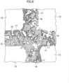
FIG. 6] FIG. 6 is a cross sectional view illustrating a part of the filter. - [
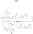
FIG. 7] FIG. 7 is a diagram showing steps for manufacturing the filter. - [
FIG. 8] FIG. 8 is a graph showing a difference in temperatures of gas flowing into pores of the filter with the catalyst in Example and Comparative Example. - [
FIG. 9] FIG. 9 is a graph showing a rate of decrease in exhaust pressure loss in Example. - Hereinafter, an embodiment of the present invention will be described with reference to the accompanying drawings. The following description of the preferred embodiment is merely illustrative in nature and is not intended to limit the scope, applications, or uses of the present invention.
- In
FIG. 1 , areference numeral 1 denotes a direct injection gasoline engine of a motor vehicle, and areference numeral 2 denotes an exhaust manifold of theengine 1. Acatalytic converter 3 is coupled to a collectingpart 2a of theexhaust manifold 2 via a connectingpipe 4, and a GPF (gasoline particulate filter)device 5 is directly connected to a downstream side of thecatalytic converter 3 in an exhaust flow direction. Anexhaust pipe 6 extends from theGPF device 5 toward the rear of the motor vehicle. - As shown in
FIG. 2 , thecatalytic converter 3 is a two-bed type in which twohoneycomb catalysts honeycomb catalyst 7 on the front stage is formed by supporting a first catalyst on a honeycomb carrier. Thehoneycomb catalyst 8 on the rear stage is formed by supporting a second catalyst on a honeycomb carrier. As each of the honeycomb carriers, it is preferable to use a honeycomb carrier having a capacity of approximately 0.5 L to 1.5 L. - The first catalyst exhibits activity on oxidation reaction of unsaturated high HC such as toluene at a temperature lower than that of the second catalyst. On the other hand, the second catalyst exhibits activity on oxidation reaction of saturated low HC such as isopentane at a temperature lower than that of the first catalyst.
- The
GPF device 5 includes afilter 10 with a catalyst housed in a filter container. Thefilter 10 with a catalyst is formed by supporting the second catalyst on a ceramic filter body formed of an inorganic porous material such as cordierite, SiC, Si3N4, sialon, and AlTiO3. As schematically shown inFIGS. 3 to 5 , thefilter 10 with the catalyst is of a honeycomb structure and includes a multitude ofcells Inflow side cells 12, whose downstream ends are each blocked by astopper 14, andoutflow side cells 13, whose upstream ends are each blocked by astopper 14, are alternately provided. Thecell 12 and thecell 13 are separated from each other by a thin partition wall (exhaust gas passage wall) 15. InFIG. 3 , areference numeral 11 denotes an exhaust gas passage. Each hatched part inFIG. 4 shows thestopper 14 at an upstream end of an exhaustgas outflow passage 13. - As the filter body, it is preferable to adopt a filter body having a capacity of 1.0 L to 2.0 L, a cell density of 200 cpsi to 300 cpsi, a thickness of each of the
partition walls 15 of 150 µm to 250 µm, a porosity of each of thepartition walls 15 of 40% to 60%, and a pore volume of each of thepartition walls 15 of approximately 70 cm3 to 400 cm3. - As shown in
FIG. 5 , the exhaust gas flows into theinflow side cells 12 of thefilter 10 with the catalyst, passes through thepartition walls 15 around thecells 12, and flows out to theoutflow side cells 13 which respectively neighbor thereto, as indicated by arrows. - As shown in
FIG. 6 , each of thepartition walls 15 hasfine pores 16 for causing thecells 12 and thecells 13 to communicate with each other, and the exhaust gas passes through thepores 16. PM in the exhaust gas adheres mainly to walls of thecells 12 and thepores 16 and is deposited thereon. - The
second catalyst 17 is supported on surfaces (filter surfaces) of thepartition walls 15 constituting theinflow side cells 12 and on inner surfaces of thepores 16. Thesecond catalyst 17 is supported on the surfaces of thepartition walls 15 constituting thecells 12 more thickly than on the inner surfaces of thepores 16. It is preferable that an amount of the supported second catalyst per unit area of the surfaces of thepartition walls 15 is 50 times or more and 500 times or less as much as an amount of the supported second catalyst per unit area of the inner surfaces of thepores 16. - In order to achieve the above-mentioned condition, it is only required to support a major amount of a total amount of the catalyst supported on the filter body on the surfaces of the
partition walls 15 constituting theinflow side cells 12. It is preferable that 65% or more and 85% or less of the total amount of the supported catalyst is supported on the surfaces of thepartition walls 15 constituting theinflow side cells 12. - It is preferable that an amount of the second catalyst supported on the surfaces of the
partition walls 15 and the inner surfaces of thepores 16 per L of the filter body is approximately 20 g/L to 100 g/L. It is only required that an amount of the second catalyst supported on the surfaces of thepartition walls 15 constituting theinflow side cells 12 is, for example, 15 g/L to 75 g/L of the filter body and an amount of the second catalyst supported on the inner surfaces of thepores 16 is, for example, 0.08 g to 0.37 g per unit pore volume. - The first catalyst having high activity for purifying the unsaturated high HC is a catalyst which contains, as an essential component, Pd-supported La2O3-containing alumina formed by supporting Pd on activated alumina containing 4% by mass of La2O3, further an OSC material (oxygen storage/release material) such as CeZr-based composite oxide, and an Rh catalyst formed by supporting Rh on the OSC material.
- The second catalyst having high activity for purifying the saturated low HC is a catalyst which contains, as an essential component, Pt-supported La2O3-containing alumina formed by supporting Pt on activated alumina containing 4% by mass of La2O3 and further, the above-mentioned OSC material.
- As described above, since the front
stage honeycomb catalyst 7 of thecatalytic converter 3 contains the first catalyst which is excellent in purifying the unsaturated high HC, the unsaturated high HC in the exhaust gas is oxidized and purified by the first catalyst, and a temperature of the exhaust gas is increased by catalytic reaction heat generated at that time. In accordance therewith, a temperature of the rearstage honeycomb catalyst 8 containing the second catalyst which is excellent in purifying the saturated low HC is increased. Accordingly, the saturated low HC in the exhaust gas is efficiently purified by the second catalyst of the rearstage honeycomb catalyst 8. - Further, a temperature of the exhaust gas is increased by the catalytic reaction heat due to the purification of HC by the
honeycomb catalysts filter 10 with the catalyst on the downstream side. Therefore, the purification of the saturated low HC by the second catalyst of thefilter 10 with the catalyst efficiently proceeds. - Further, saturated low HC is generated by cracking of the unsaturated high HC by the front-
stage honeycomb catalyst 7 of thecatalytic converter 3, and the saturated low HC flows to the rearstage honeycomb catalyst 8 and thefilter 10 with the catalyst. Since the second catalysts of the rearstage honeycomb catalyst 8 and thefilter 10 with the catalyst are excellent in purifying the unsaturated low HC, the saturated low HC generated by the above-mentioned cracking is efficiently purified by the second catalysts of the rearstage honeycomb catalyst 8 and thefilter 10 with the catalyst. - In the
filter 10 with the catalyst, the second catalyst is thickly supported on the surfaces of thepartition walls 15 constituting theinflow side cells 12 and is thinly supported on the inner surfaces of thepores 16. Accordingly, since the exhaust gas is actively purified on the surfaces of thepartition walls 15, the exhaust gas whose temperature has been increased passes through thepores 16. Therefore, although the second catalyst is thinly supported on the inner surfaces of thepores 16, the temperature of the exhaust gas passing through thepores 16 is high and thus, the purification of the exhaust gas by the second catalyst efficiently proceeds. - As shown in
FIG. 7 , one end portion of the filter body (with a catalyst unsupported) 21 is immersed incatalyst slurry 23 of the above-mentioned second catalyst stored in a first container 22 and is pulled up. In thefilter body 21, theinflow side cells 12 and theoutflow side cells 13 are alternately provided. - An upstream end side of the
filter body 21 is immersed in thecatalyst slurry 23 and is pulled up. This causes thecatalyst slurry 23 to adhere to inner surfaces on an upstream end side of theinflow side cells 12 of thefilter body 21. - Subsequently, a
vacuum pump 24 is connected to a downstream end of thefilter body 21, and thepump 24 is operated to render a pressure of theoutflow side cells 13 of thefilter body 21 negative. When the pressure of theoutflow side cells 13 becomes negative, thecatalyst slurry 23 adhering to the upstream end side of theinflow side cells 12 is attracted to downstream sides of thecells 12 and infiltrates into thepores 16 of thepartition walls 15. Thus, the catalyst is supported on the inner surfaces of thepores 16 of thefilter 21. - Here, the
catalyst slurry 23 stored in the first container 22 is adjusted to have a viscosity at which thecatalyst slurry 23 easily infiltrates into thepores 16 of thepartition walls 15. - By heating the
filter body 21, the catalyst adhering to the inner surfaces of thepores 16 of thepartition walls 15 is dried. This drying is conducted, for example, by holding thefilter body 21 at a temperature of 150°C for two hours. - An end portion of the dried
filter body 21 on an upstream end side is immersed incatalyst slurry 26 of the above-mentioned second catalyst stored in asecond container 25 and is pulled up. This causes thecatalyst slurry 26 to adhere to the inner surfaces on an upstream side of theinflow side cells 12 of thefilter body 21. - Subsequently, a
vacuum pump 24 is connected to a downstream end of thefilter body 21, and thepump 24 is operated to render a pressure of theoutflow side cells 13 of thefilter body 21 negative. When the pressure of theoutflow side cell 13 becomes negative, thecatalyst slurry 23 adhering to the upstream end side of theinflow side cells 12 is attracted to downstream sides of thecells 12. Thus, the catalyst is supported on the inner surfaces of theinflow side cells 12 of thefilter 21, that is, on surfaces of thepartition walls 15. - Here, the
catalyst slurry 26 stored in thesecond container 25 is made to have a viscosity higher than that of thecatalyst slurry 23 stored in the first container 22 so as to hinder thecatalyst slurry 26 from entering thepores 16 of thepartition walls 15 upon vacuuming performed by thevacuum pump 24. - When the
catalyst slurry 26 is supported on the surfaces of thepartition walls 15, although a part of thepores 16 are blocked, thecatalyst slurry 26 supported on the surfaces of thepartition walls 15 becomes porous catalyst layers by the subsequent calcination, thereby allowing the exhaust gas to pass through the catalyst layers and to flow into thepores 16. - By heating the
filter body 21 having undergone the second step, the catalyst adhering to the surfaces of thepartition walls 15 of thefilter body 21 and the catalyst adhering to the inner surfaces of thepores 16 are calcined. This calcining is conducted, for example, by holding thefilter body 21 at a temperature of 500°C for two hours. If necessary, the drying step (in which thefilter body 21 is held at the temperature of 150°C for two hours) is interposed prior to the calcining. - As described above, the
filter 10 with the catalyst, in which the second catalyst is supported on the surfaces of thepartition walls 15 and the inner surfaces of thepores 16 of theinflow side cells 12 of thefilter body 21 is obtained. - The
GPF device 5 in which thefilter 10 with the catalyst is housed in the filter container is connected to thecatalytic converter 3 in which thehoneycomb catalysts catalytic converter 3 is connected to theexhaust manifold 2 via aconnection pipe 4, and theGPF device 5 is joined to theexhaust pipe 6. Thus, the device for treating exhaust gas from an engine is obtained. - As the
filter body 21, a filter formed of cordierite and having a capacity of 1.3 L was prepared. A cell density thereof was 250 cpsi, a partition wall thickness was 200 µm, a porosity of each of the partition walls was 50%, and a pore volume of each of the partition walls was approximately 100 cm3. - In Example, a filter with a catalyst was obtained by supporting 15 g/L of the second catalyst (the supported amount in the above-mentioned first step) on inner surfaces of pores of the
filter body 21 and supporting 45 g/L of the second catalyst (the supported amount in the above-mentioned second step) on surfaces of partition walls constitutinginflow side cells 12. - A total area of the surfaces of partition walls constituting the
inflow side cells 12 of thefilter body 21 was 1.82 m2, and a total area of the inner surfaces of pores of thefilter body 21 calculated from the concept of the hydraulic diameter was 258.09 m2. Accordingly, an amount of the supported catalyst per unit area of the surfaces of the partition walls (a filter surface) constituting theinflow side cells 12 was 24.73 g/m2, and an amount of the supported catalyst per unit area of the inner surfaces of the pores was 0.058 g/m2. Therefore, the amount of the supported catalyst per unit area of the surfaces of partition walls constituting theinflow side cells 12 was approximately 426 times as much as the amount of the supported catalyst per unit area of the inner surfaces of the pores. - In Comparative Example, a filter with a catalyst was obtained by supporting 60 g/L of the second catalyst on inner surfaces of pores of the
filter body 21. An amount of catalyst supported on surfaces of partition walls constitutinginflow side cells 12 was set to zero. An amount of the supported catalyst per unit area of the inner surfaces of the pores was 0.23 g/m2. - An estimation was made of a temperature of gas flowing into the pores upon flowing a methane gas (with a gas temperature of 300°C and a CH4 concentration of 160 ppmC at an inlet of the filter) as simulated exhaust gas to the filter with the catalyst in each of Example and Comparative Example.
- A total amount of CH4 (0.06 mol) flowing into the filter was determined from a CH4 concentration, a gas flow rate of 10 g/sec., and a gas flowing time of 60 seconds. In the filter in Example, assuming that 75% of the total amount of CH4 was purified by the second catalyst supported on the surfaces of partition walls of the
inflow side cells 12, a rising temperature of the gas was determined from a heat capacity of 736 J/kg·K of the filter and a weight of 0.45 kg thereof and the below-mentioned heat of combustion of CH4. In the filter in Comparative Example, a CH4 purification rate in the inflow side cells was zero. The results are shown in Table 1 andFIG. 8 .
CH4 + 2O2 → CO2 + 2H2O + 891 kJ/mol
[Table 1] Comparative Example Example CH4 Concentration at Filter Inlet 160 ppmC 160 ppmC CH4 Purification Rate in Inflow Side Cells 0% 75% Amount of Heat Generated in Association with CH4 Combustion 0 4009 J Temperature of Gas Flowing into Pores 300°C 312.1°C - Table 1 shows that by supporting the catalyst on the surfaces of partition walls constituting the
inflow side cells 12 as in Example, the temperature of the exhaust gas flowing into the pores due to the catalytic reaction heat is increased, which is advantageous in purification of the exhaust gas by the catalyst supported on the inner surfaces of pores. - Amounts of supported catalyst in Example and Comparative Example were the same, 60 g/L. In Comparative Example, a total amount of the catalyst was supported on the inner surfaces of the pores, whereas in Example, the amount of catalyst supported on the inner surfaces of the pores was set to 15 g/L by supporting 3/4 of a total amount of the catalyst on the surfaces of partition walls constituting the
inflow side cells 12. Therefore, in the filter in Example, a porosity of the partition walls was approximately 5.4% larger than that of the filter in Comparative Example. - Assuming that exhaust pressure loss in an engine due to the filter with the catalyst depended only on the porosity, a rate of decrease in exhaust pressure loss in Example, with exhaust pressure loss in Comparative Example as reference (100%), was calculated. In the calculation, an exhaust gas flow rate was set to 0.15 g/sec., and a temperature of an exhaust gas was set to 550°C. Results are shown in
FIG. 9 . - The exhaust pressure loss in Example was approximately 93% of that in Comparative Example. This result shows that by supporting a portion of the catalyst on the surfaces of partition walls constituting the
inflow side cells 12 as in Example, the exhaust pressure loss becomes small, thereby leading to advantages in enhancing scavenging performance of an engine and thus, in enhancing fuel consumption. - 1
- Gasoline Engine
- 2
- Exhaust Manifold
- 3
- Catalytic Converter
- 5
- GPF Device
- 7
- Front Stage Honeycomb Catalyst
- 8
- Rear Stage Honeycomb Catalyst
- 10
- Filter with Catalyst
- 12
- Inflow Side Cells
- 13
- Outflow Side Cells
- 14
- Stoppers
- 15
- Partition Walls
- 16
- Pores
- 17
- Second Catalyst
Claims (4)
- A device for treating exhaust gas from an engine (1), the device comprisinga catalytic converter (3) provided in an exhaust gas passage of an engine (1); anda filter device (5) provided on a downstream side of the catalytic converter (3) in the exhaust gas passage,the catalytic converter (3) includes a catalyst (7) on a front stage that includes a first catalyst which exhibits activity in oxidation reaction of unsaturated hydrocarbons whose number of carbon atoms is 6 to 9, a catalyst (8) on a rear stage that is provided on a downstream side of the catalyst (7) on the front stage and includes a second catalyst which exhibits activity in oxidation reaction of saturated hydrocarbons whose number of carbon atoms is 5 or smaller, and a catalyst container housing the catalyst (7) on the front stage and the catalyst (8) on the rear stage together,the filter device (5) including a filter (10) porous and collecting particulate matter in exhaust gas and a filter container housing the porous filter, the exhaust gas passing through pores (16) of the filter (10) from surfaces of the filter (10) and being discharged,the catalytic converter (3) being connected to an exhaust manifold (2) of the engine (1) via a connecting pipe (4),the filter device (5) being directly connected to the catalytic converter (3),a catalyst (17) being supported on the surfaces of the filter (10) and inner surfaces of the pores (16) exhibiting activity in oxidation reaction of saturated hydrocarbons whose number of carbon atoms is 5 or smaller,the catalyst (17) being supported on the surfaces of the filter (10) more thickly than on the inner surfaces of the pores (16),the first catalyst containing, as an essential component, Pd-supported La2O3-containing alumina formed by supporting Pd on activated alumina containing 4% by mass of La2O3, further OSC material and an Rh catalyst formed by supporting Rh on the OSC material,the second catalyst and the catalyst (17) containing, as an essential component, Pt-supported La2O3-containing alumina formed by supporting Pt on activated alumina containing 4% by mass of La2O3 and further, the OSC material.
- The device for treating exhaust gas from an engine of claim 1, wherein
an amount of the supported catalyst (17) per unit area of the surfaces of the filter (10) is 50 times or more and 500 times or less as much as an amount of the supported catalyst (17) per unit area of the inner surfaces of the pores (16). - A method for manufacturing a device for treating exhaust gas from an engine of claim 1, the method comprising:a first step of immersing an upstream end side of a filter (10), which is porous, in first catalyst slurry in which a catalyst for purifying the exhaust gas is dispersed, pulling up the filter (10), connecting a vacuum pump to a downstream end of the filter (10), and attracting, to a downstream side of the filter (10), the first catalyst slurry adhering to the upstream end side, thereby supporting the catalyst on inner surfaces of the pores of the filter (10), the porous filter (10) having pores (16) through which the exhaust gas from the engine (1) passes;a second step of immersing the upstream end side of the filter (10) having undergone the first step in second catalyst slurry in which the catalyst is dispersed, pulling up the filter (10), connecting the vacuum pump to the downstream end of the filter (10), and attracting, to the downstream side of the filter (10), the second catalyst slurry adhering to the upstream end side, thereby supporting the catalyst on surfaces of the filter (10) in a thickness greater than a thickness of the catalyst supported on the inner surfaces of the pores (16) of the filter (10); anda third step of providing the filter (10) having undergone the second step in an exhaust gas passage of the engine (1), whereinthe second catalyst slurry is set to have a viscosity higher than the viscosity of the first catalyst slurry.
- The method for manufacturing a device for treating exhaust gas from an engine of claim 3, the method further comprising:a step of drying the catalyst supported on the inner surfaces of the pores (16) of the filter (10) between the first step and the second step, anda step of calcining the catalyst supported on the surfaces of the filter (10) and the catalyst supported on the inner surfaces of the pores (16) between the second step and the third step.
Applications Claiming Priority (2)
| Application Number | Priority Date | Filing Date | Title |
|---|---|---|---|
| JP2017110551A JP6458827B2 (en) | 2017-06-05 | 2017-06-05 | Engine exhaust gas treatment device |
| PCT/JP2018/019879 WO2018225514A1 (en) | 2017-06-05 | 2018-05-23 | Device for treating exhaust gas from engine and method for manufacturing said device |
Publications (3)
| Publication Number | Publication Date |
|---|---|
| EP3617465A1 EP3617465A1 (en) | 2020-03-04 |
| EP3617465A4 EP3617465A4 (en) | 2020-04-08 |
| EP3617465B1 true EP3617465B1 (en) | 2023-04-19 |
Family
ID=64566269
Family Applications (1)
| Application Number | Title | Priority Date | Filing Date |
|---|---|---|---|
| EP18814241.8A Active EP3617465B1 (en) | 2017-06-05 | 2018-05-23 | Device for treating exhaust gas from engine and method for manufacturing said device |
Country Status (5)
| Country | Link |
|---|---|
| US (1) | US10870082B2 (en) |
| EP (1) | EP3617465B1 (en) |
| JP (1) | JP6458827B2 (en) |
| CN (1) | CN110709588B (en) |
| WO (1) | WO2018225514A1 (en) |
Family Cites Families (22)
| Publication number | Priority date | Publication date | Assignee | Title |
|---|---|---|---|---|
| JP3879522B2 (en) * | 2002-01-28 | 2007-02-14 | トヨタ自動車株式会社 | Exhaust purification device for internal combustion engine, and catalyst carrying method for carrying catalyst on particulate filter |
| JP3936238B2 (en) * | 2002-05-20 | 2007-06-27 | 株式会社デンソー | Catalyst body and method for producing catalyst body |
| US20040176246A1 (en) * | 2003-03-05 | 2004-09-09 | 3M Innovative Properties Company | Catalyzing filters and methods of making |
| JP4907860B2 (en) * | 2004-11-11 | 2012-04-04 | 株式会社キャタラー | Filter catalyst |
| US8883667B2 (en) * | 2006-10-11 | 2014-11-11 | Nikki-Universal Co., Ltd. | Purification catalyst for reflow furnace gas, method for preventing contamination of reflow furnace, and reflow furnace |
| WO2009130869A1 (en) * | 2008-04-22 | 2009-10-29 | 本田技研工業株式会社 | Oxidation catalyst and oxidation catalyst device for exhaust gas purification |
| JP5409070B2 (en) * | 2009-03-24 | 2014-02-05 | 日本碍子株式会社 | Exhaust gas purification device manufacturing method and exhaust gas purification device |
| CN102380412B (en) * | 2011-09-06 | 2014-04-30 | 太原理工大学 | Method for preparing MFI catalyst carrying transition elements and MFI catalyst application |
| GB201200783D0 (en) * | 2011-12-12 | 2012-02-29 | Johnson Matthey Plc | Substrate monolith comprising SCR catalyst |
| JP5939010B2 (en) * | 2012-04-18 | 2016-06-22 | マツダ株式会社 | Exhaust gas purification catalyst device |
| GB201219600D0 (en) * | 2012-10-31 | 2012-12-12 | Johnson Matthey Plc | Catalysed soot filter |
| JP6007864B2 (en) * | 2013-06-10 | 2016-10-12 | トヨタ自動車株式会社 | Exhaust purification filter |
| WO2015059904A1 (en) * | 2013-10-23 | 2015-04-30 | マツダ株式会社 | Exhaust gas purifying catalyst device and method for purifying exhaust gas |
| DE112014004876T5 (en) | 2013-10-23 | 2016-07-07 | Mazda Motor Corporation | Catalyst device for exhaust gas purification and process for exhaust gas purification |
| US10864502B2 (en) * | 2013-12-16 | 2020-12-15 | Basf Corporation | Manganese-containing diesel oxidation catalyst |
| CN105658309B (en) * | 2014-08-29 | 2018-04-13 | 马自达汽车株式会社 | Exhaust purification catalytic device and exhaust purifying method |
| CN104234793A (en) * | 2014-09-03 | 2014-12-24 | 江阴华音陶瓷机电科技有限公司 | Diesel engine exhaust filter |
| JP2016055282A (en) * | 2014-09-11 | 2016-04-21 | 日本碍子株式会社 | Honeycomb structure |
| US10232299B2 (en) | 2014-09-11 | 2019-03-19 | Ngk Insulators, Ltd. | Honeycomb structure |
| JP6217677B2 (en) * | 2015-03-24 | 2017-10-25 | マツダ株式会社 | Exhaust gas purification catalyst device and exhaust gas purification method |
| JP6431823B2 (en) | 2015-07-13 | 2018-11-28 | 株式会社Soken | Exhaust gas purification filter |
| JP6594149B2 (en) | 2015-10-05 | 2019-10-23 | 株式会社キャタラー | Exhaust gas purification device |
-
2017
- 2017-06-05 JP JP2017110551A patent/JP6458827B2/en active Active
-
2018
- 2018-05-23 US US16/619,078 patent/US10870082B2/en active Active
- 2018-05-23 CN CN201880036612.2A patent/CN110709588B/en not_active Expired - Fee Related
- 2018-05-23 EP EP18814241.8A patent/EP3617465B1/en active Active
- 2018-05-23 WO PCT/JP2018/019879 patent/WO2018225514A1/en unknown
Also Published As
| Publication number | Publication date |
|---|---|
| US20200094188A1 (en) | 2020-03-26 |
| US10870082B2 (en) | 2020-12-22 |
| WO2018225514A1 (en) | 2018-12-13 |
| EP3617465A4 (en) | 2020-04-08 |
| JP6458827B2 (en) | 2019-01-30 |
| EP3617465A1 (en) | 2020-03-04 |
| CN110709588B (en) | 2021-10-22 |
| CN110709588A (en) | 2020-01-17 |
| JP2018204537A (en) | 2018-12-27 |
Similar Documents
| Publication | Publication Date | Title |
|---|---|---|
| JP5726414B2 (en) | Catalyst-carrying filter and exhaust gas purification system | |
| US10610830B2 (en) | Honeycomb structure | |
| EP2501464B1 (en) | Zoned catalyzed soot filter | |
| JP6023395B2 (en) | Catalyst support filter | |
| KR102107978B1 (en) | Pollutant abatement system for gasoline vehicles | |
| JP2017185481A (en) | Honeycomb structure | |
| KR102605894B1 (en) | Catalytic wall-flow filter having a membrane | |
| JP2011509826A (en) | Catalyst filter | |
| JP6092068B2 (en) | Catalyst supported honeycomb filter | |
| JP2009165922A (en) | Exhaust gas purification catalyst | |
| JP2009285605A (en) | Catalyst for cleaning exhaust gas | |
| US11420189B2 (en) | Exhaust gas purification catalyst | |
| US20220184591A1 (en) | Particulate filter | |
| EP1510670B1 (en) | Exhaust gas-purifying apparatus | |
| KR20120095747A (en) | Multi-functional particulate filter and exhaust gas filtering device using this | |
| US11808188B2 (en) | Particulate filter | |
| EP3617465B1 (en) | Device for treating exhaust gas from engine and method for manufacturing said device | |
| US10661216B2 (en) | Soot particle filter with storage cells for a catalyst | |
| JP2009273989A (en) | Exhaust gas cleaning device | |
| KR20130110136A (en) | Multi-functional particulate filter and exhaust gas filtering device using this | |
| WO2014178632A1 (en) | Catalyst system for purifying exhaust gas from gasoline engine |
Legal Events
| Date | Code | Title | Description |
|---|---|---|---|
| STAA | Information on the status of an ep patent application or granted ep patent |
Free format text: STATUS: THE INTERNATIONAL PUBLICATION HAS BEEN MADE |
|
| PUAI | Public reference made under article 153(3) epc to a published international application that has entered the european phase |
Free format text: ORIGINAL CODE: 0009012 |
|
| STAA | Information on the status of an ep patent application or granted ep patent |
Free format text: STATUS: REQUEST FOR EXAMINATION WAS MADE |
|
| REG | Reference to a national code |
Ref country code: DE Ref legal event code: R079 Ref document number: 602018048666 Country of ref document: DE Free format text: PREVIOUS MAIN CLASS: F01N0003035000 Ipc: B01D0039200000 |
|
| 17P | Request for examination filed |
Effective date: 20191128 |
|
| AK | Designated contracting states |
Kind code of ref document: A1 Designated state(s): AL AT BE BG CH CY CZ DE DK EE ES FI FR GB GR HR HU IE IS IT LI LT LU LV MC MK MT NL NO PL PT RO RS SE SI SK SM TR |
|
| AX | Request for extension of the european patent |
Extension state: BA ME |
|
| A4 | Supplementary search report drawn up and despatched |
Effective date: 20200306 |
|
| RIC1 | Information provided on ipc code assigned before grant |
Ipc: F01N 3/24 20060101ALI20200302BHEP Ipc: F01N 3/10 20060101ALI20200302BHEP Ipc: F01N 3/28 20060101ALI20200302BHEP Ipc: B01D 39/20 20060101AFI20200302BHEP Ipc: F01N 3/035 20060101ALI20200302BHEP Ipc: B01D 46/00 20060101ALI20200302BHEP Ipc: F01N 3/022 20060101ALI20200302BHEP Ipc: F01N 13/00 20100101ALI20200302BHEP Ipc: B01D 53/94 20060101ALI20200302BHEP Ipc: F01N 3/033 20060101ALI20200302BHEP |
|
| DAV | Request for validation of the european patent (deleted) | ||
| DAX | Request for extension of the european patent (deleted) | ||
| STAA | Information on the status of an ep patent application or granted ep patent |
Free format text: STATUS: EXAMINATION IS IN PROGRESS |
|
| 17Q | First examination report despatched |
Effective date: 20210304 |
|
| GRAP | Despatch of communication of intention to grant a patent |
Free format text: ORIGINAL CODE: EPIDOSNIGR1 |
|
| STAA | Information on the status of an ep patent application or granted ep patent |
Free format text: STATUS: GRANT OF PATENT IS INTENDED |
|
| INTG | Intention to grant announced |
Effective date: 20221206 |
|
| GRAS | Grant fee paid |
Free format text: ORIGINAL CODE: EPIDOSNIGR3 |
|
| GRAA | (expected) grant |
Free format text: ORIGINAL CODE: 0009210 |
|
| STAA | Information on the status of an ep patent application or granted ep patent |
Free format text: STATUS: THE PATENT HAS BEEN GRANTED |
|
| AK | Designated contracting states |
Kind code of ref document: B1 Designated state(s): AL AT BE BG CH CY CZ DE DK EE ES FI FR GB GR HR HU IE IS IT LI LT LU LV MC MK MT NL NO PL PT RO RS SE SI SK SM TR |
|
| REG | Reference to a national code |
Ref country code: GB Ref legal event code: FG4D |
|
| REG | Reference to a national code |
Ref country code: CH Ref legal event code: EP |
|
| REG | Reference to a national code |
Ref country code: DE Ref legal event code: R096 Ref document number: 602018048666 Country of ref document: DE |
|
| REG | Reference to a national code |
Ref country code: IE Ref legal event code: FG4D |
|
| REG | Reference to a national code |
Ref country code: AT Ref legal event code: REF Ref document number: 1560784 Country of ref document: AT Kind code of ref document: T Effective date: 20230515 |
|
| PGFP | Annual fee paid to national office [announced via postgrant information from national office to epo] |
Ref country code: DE Payment date: 20230517 Year of fee payment: 6 |
|
| REG | Reference to a national code |
Ref country code: LT Ref legal event code: MG9D |
|
| REG | Reference to a national code |
Ref country code: NL Ref legal event code: MP Effective date: 20230419 |
|
| REG | Reference to a national code |
Ref country code: AT Ref legal event code: MK05 Ref document number: 1560784 Country of ref document: AT Kind code of ref document: T Effective date: 20230419 |
|
| PG25 | Lapsed in a contracting state [announced via postgrant information from national office to epo] |
Ref country code: NL Free format text: LAPSE BECAUSE OF FAILURE TO SUBMIT A TRANSLATION OF THE DESCRIPTION OR TO PAY THE FEE WITHIN THE PRESCRIBED TIME-LIMIT Effective date: 20230419 |
|
| PG25 | Lapsed in a contracting state [announced via postgrant information from national office to epo] |
Ref country code: SE Free format text: LAPSE BECAUSE OF FAILURE TO SUBMIT A TRANSLATION OF THE DESCRIPTION OR TO PAY THE FEE WITHIN THE PRESCRIBED TIME-LIMIT Effective date: 20230419 Ref country code: PT Free format text: LAPSE BECAUSE OF FAILURE TO SUBMIT A TRANSLATION OF THE DESCRIPTION OR TO PAY THE FEE WITHIN THE PRESCRIBED TIME-LIMIT Effective date: 20230821 Ref country code: NO Free format text: LAPSE BECAUSE OF FAILURE TO SUBMIT A TRANSLATION OF THE DESCRIPTION OR TO PAY THE FEE WITHIN THE PRESCRIBED TIME-LIMIT Effective date: 20230719 Ref country code: ES Free format text: LAPSE BECAUSE OF FAILURE TO SUBMIT A TRANSLATION OF THE DESCRIPTION OR TO PAY THE FEE WITHIN THE PRESCRIBED TIME-LIMIT Effective date: 20230419 Ref country code: AT Free format text: LAPSE BECAUSE OF FAILURE TO SUBMIT A TRANSLATION OF THE DESCRIPTION OR TO PAY THE FEE WITHIN THE PRESCRIBED TIME-LIMIT Effective date: 20230419 |
|
| PG25 | Lapsed in a contracting state [announced via postgrant information from national office to epo] |
Ref country code: RS Free format text: LAPSE BECAUSE OF FAILURE TO SUBMIT A TRANSLATION OF THE DESCRIPTION OR TO PAY THE FEE WITHIN THE PRESCRIBED TIME-LIMIT Effective date: 20230419 Ref country code: PL Free format text: LAPSE BECAUSE OF FAILURE TO SUBMIT A TRANSLATION OF THE DESCRIPTION OR TO PAY THE FEE WITHIN THE PRESCRIBED TIME-LIMIT Effective date: 20230419 Ref country code: LV Free format text: LAPSE BECAUSE OF FAILURE TO SUBMIT A TRANSLATION OF THE DESCRIPTION OR TO PAY THE FEE WITHIN THE PRESCRIBED TIME-LIMIT Effective date: 20230419 Ref country code: LT Free format text: LAPSE BECAUSE OF FAILURE TO SUBMIT A TRANSLATION OF THE DESCRIPTION OR TO PAY THE FEE WITHIN THE PRESCRIBED TIME-LIMIT Effective date: 20230419 Ref country code: IS Free format text: LAPSE BECAUSE OF FAILURE TO SUBMIT A TRANSLATION OF THE DESCRIPTION OR TO PAY THE FEE WITHIN THE PRESCRIBED TIME-LIMIT Effective date: 20230819 Ref country code: HR Free format text: LAPSE BECAUSE OF FAILURE TO SUBMIT A TRANSLATION OF THE DESCRIPTION OR TO PAY THE FEE WITHIN THE PRESCRIBED TIME-LIMIT Effective date: 20230419 Ref country code: GR Free format text: LAPSE BECAUSE OF FAILURE TO SUBMIT A TRANSLATION OF THE DESCRIPTION OR TO PAY THE FEE WITHIN THE PRESCRIBED TIME-LIMIT Effective date: 20230720 Ref country code: AL Free format text: LAPSE BECAUSE OF FAILURE TO SUBMIT A TRANSLATION OF THE DESCRIPTION OR TO PAY THE FEE WITHIN THE PRESCRIBED TIME-LIMIT Effective date: 20230419 |
|
| PG25 | Lapsed in a contracting state [announced via postgrant information from national office to epo] |
Ref country code: FI Free format text: LAPSE BECAUSE OF FAILURE TO SUBMIT A TRANSLATION OF THE DESCRIPTION OR TO PAY THE FEE WITHIN THE PRESCRIBED TIME-LIMIT Effective date: 20230419 |
|
| REG | Reference to a national code |
Ref country code: CH Ref legal event code: PL |
|
| PG25 | Lapsed in a contracting state [announced via postgrant information from national office to epo] |
Ref country code: SK Free format text: LAPSE BECAUSE OF FAILURE TO SUBMIT A TRANSLATION OF THE DESCRIPTION OR TO PAY THE FEE WITHIN THE PRESCRIBED TIME-LIMIT Effective date: 20230419 |
|
| PG25 | Lapsed in a contracting state [announced via postgrant information from national office to epo] |
Ref country code: MC Free format text: LAPSE BECAUSE OF FAILURE TO SUBMIT A TRANSLATION OF THE DESCRIPTION OR TO PAY THE FEE WITHIN THE PRESCRIBED TIME-LIMIT Effective date: 20230419 |
|
| REG | Reference to a national code |
Ref country code: DE Ref legal event code: R097 Ref document number: 602018048666 Country of ref document: DE |
|
| REG | Reference to a national code |
Ref country code: BE Ref legal event code: MM Effective date: 20230531 |
|
| PG25 | Lapsed in a contracting state [announced via postgrant information from national office to epo] |
Ref country code: SM Free format text: LAPSE BECAUSE OF FAILURE TO SUBMIT A TRANSLATION OF THE DESCRIPTION OR TO PAY THE FEE WITHIN THE PRESCRIBED TIME-LIMIT Effective date: 20230419 Ref country code: SK Free format text: LAPSE BECAUSE OF FAILURE TO SUBMIT A TRANSLATION OF THE DESCRIPTION OR TO PAY THE FEE WITHIN THE PRESCRIBED TIME-LIMIT Effective date: 20230419 Ref country code: RO Free format text: LAPSE BECAUSE OF FAILURE TO SUBMIT A TRANSLATION OF THE DESCRIPTION OR TO PAY THE FEE WITHIN THE PRESCRIBED TIME-LIMIT Effective date: 20230419 Ref country code: MC Free format text: LAPSE BECAUSE OF FAILURE TO SUBMIT A TRANSLATION OF THE DESCRIPTION OR TO PAY THE FEE WITHIN THE PRESCRIBED TIME-LIMIT Effective date: 20230419 Ref country code: LU Free format text: LAPSE BECAUSE OF NON-PAYMENT OF DUE FEES Effective date: 20230523 Ref country code: LI Free format text: LAPSE BECAUSE OF NON-PAYMENT OF DUE FEES Effective date: 20230531 Ref country code: EE Free format text: LAPSE BECAUSE OF FAILURE TO SUBMIT A TRANSLATION OF THE DESCRIPTION OR TO PAY THE FEE WITHIN THE PRESCRIBED TIME-LIMIT Effective date: 20230419 Ref country code: DK Free format text: LAPSE BECAUSE OF FAILURE TO SUBMIT A TRANSLATION OF THE DESCRIPTION OR TO PAY THE FEE WITHIN THE PRESCRIBED TIME-LIMIT Effective date: 20230419 Ref country code: CZ Free format text: LAPSE BECAUSE OF FAILURE TO SUBMIT A TRANSLATION OF THE DESCRIPTION OR TO PAY THE FEE WITHIN THE PRESCRIBED TIME-LIMIT Effective date: 20230419 Ref country code: CH Free format text: LAPSE BECAUSE OF NON-PAYMENT OF DUE FEES Effective date: 20230531 |
|
| PLBE | No opposition filed within time limit |
Free format text: ORIGINAL CODE: 0009261 |
|
| STAA | Information on the status of an ep patent application or granted ep patent |
Free format text: STATUS: NO OPPOSITION FILED WITHIN TIME LIMIT |
|
| REG | Reference to a national code |
Ref country code: IE Ref legal event code: MM4A |
|
| 26N | No opposition filed |
Effective date: 20240122 |
|
| GBPC | Gb: european patent ceased through non-payment of renewal fee |
Effective date: 20230719 |
|
| PG25 | Lapsed in a contracting state [announced via postgrant information from national office to epo] |
Ref country code: IE Free format text: LAPSE BECAUSE OF NON-PAYMENT OF DUE FEES Effective date: 20230523 |