JP2005290921A - Door lock device - Google Patents
Door lock device Download PDFInfo
- Publication number
- JP2005290921A JP2005290921A JP2004110833A JP2004110833A JP2005290921A JP 2005290921 A JP2005290921 A JP 2005290921A JP 2004110833 A JP2004110833 A JP 2004110833A JP 2004110833 A JP2004110833 A JP 2004110833A JP 2005290921 A JP2005290921 A JP 2005290921A
- Authority
- JP
- Japan
- Prior art keywords
- door
- gear
- lock device
- dead bolt
- knob
- Prior art date
- Legal status (The legal status is an assumption and is not a legal conclusion. Google has not performed a legal analysis and makes no representation as to the accuracy of the status listed.)
- Granted
Links
Images

Landscapes
- Lock And Its Accessories (AREA)
Abstract
Description
本発明はドアロック装置に関する。 The present invention relates to a door lock device.
ドアを閉扉状態に保つドアロック装置は、通常の場合、ドア側に錠前ユニットを配置しているが、最近ではドア側でなくドア枠側に電動式の錠前ユニットを設けるという提案もなされている。その例を特許文献1、2に見ることができる。特許文献1、2にはICカード型のエントリー手段を用いて施錠・解錠を行う構成も記載されている。
電動式の錠前ユニットを用いる場合、通常は電気的に施錠・解錠を行うにしても、停電の際は手動による施錠・解錠が可能であることが望ましい。またキーレスエントリー手段により施錠・解錠を行う構成とする場合、キーレスエントリー手段を携帯していなければ施錠・解錠を行えないというのでは不便なので、少なくとも室内側からは、キーレスエントリー手段を携帯していなくても手動で施錠・解錠を行えることが望まれる。 When using an electric lock unit, it is desirable that manual locking / unlocking is possible in the event of a power failure, even though the locking / unlocking is normally performed electrically. In addition, when it is configured to lock / unlock by keyless entry means, it is inconvenient that locking / unlocking cannot be performed unless the keyless entry means is carried, so at least from the indoor side, carry the keyless entry means. It is desirable to be able to manually lock and unlock even if not.
本発明は上記の点に鑑みてなされたものであり、その目的とするところは、ドア枠側に電動式の錠前ユニットを配置するドアロック装置において、デッドボルトの出し入れをモータで行うか手動で行うかを簡単に選択できるようにすることにある。またキーレスエントリー手段を携帯していなくても室内側では手動で簡単に施錠・解錠を行えるようにすることにある。 The present invention has been made in view of the above points. The object of the present invention is to provide a door lock device in which an electric lock unit is disposed on the door frame side. It is to make it easy to choose what to do. Another object is to enable easy manual locking and unlocking indoors without carrying keyless entry means.
(1)本発明のドアロック装置は、以下の構成を備える錠前ユニットを用いる。
(a)ドア枠に固定される筐体
(b)垂直面内で回動して前記筐体から出没し、ドアに設けられたボルト受けに係合してドアの閉扉状態を保ち、このボルト受けから抜け出したときはドアの開扉を可能とするデッドボルト
(c)前記デッドボルトの回動の動力源となるモータ
(d)前記モータと前記デッドボルトとを連結する動力伝達手段
(e)前記動力伝達手段に付設されたクラッチ手段
(f)前記クラッチ手段が前記モータからデッドボルトへの動力伝達を断ったとき、モータに代わってデッドボルトを回動させる手動操作手段。
(1) The door lock device of the present invention uses a lock unit having the following configuration.
(A) Housing fixed to the door frame (b) Rotating in a vertical plane, protruding and retracting from the housing, and engaging with a bolt receiver provided on the door to keep the door closed, this bolt A dead bolt that enables the door to be opened when the door is pulled out (c) a motor that is a power source for turning the dead bolt (d) a power transmission means (e) that connects the motor and the dead bolt Clutch means attached to the power transmission means (f) Manual operation means for rotating the dead bolt instead of the motor when the clutch means cuts off power transmission from the motor to the dead bolt.
(2)前記構成のドアロック装置において、前記動力伝達手段が歯車列からなる。 (2) In the door lock device having the above-described configuration, the power transmission means includes a gear train.
(3)前記構成のドアロック装置において、前記クラッチ手段を構成するのが前記歯車列の中の1個の歯車であり、この歯車が前後の歯車を連結したときがクラッチの接続状態、前後の歯車の連結を解除したときがクラッチの切断状態である。 (3) In the door lock device having the above-described configuration, the clutch means constitutes one gear in the gear train, and when this gear connects the front and rear gears, the clutch is connected, The clutch is disengaged when the gears are disconnected.
(4)前記構成のドアロック装置において、前記手動操作手段は、前記歯車列のうち、前記クラッチ手段より後段側に位置する歯車にかみ合うラックを含む。 (4) In the door lock device having the above-described configuration, the manual operation means includes a rack that meshes with a gear that is located on the rear side of the clutch means in the gear train.
(5)前記構成のドアロック装置において、前記歯車列は、前記クラッチ手段より前段側にウォームとウォーム歯車の組み合わせを含む。 (5) In the door lock device configured as described above, the gear train includes a combination of a worm and a worm gear on the front side of the clutch means.
(6)前記構成のドアロック装置において、前記ラックには前記ドア枠の外面に突き出すつまみが取り付けられるとともに、このつまみを覆う開閉自在なカバーが設けられる。 (6) In the door lock device having the above-described configuration, a knob protruding to the outer surface of the door frame is attached to the rack, and an openable / closable cover for covering the knob is provided.
(7)前記構成のドアロック装置において、前記クラッチ手段は、前記カバーを閉じたときに接続状態となり、カバーを開いたときに切断状態となる。 (7) In the door lock device configured as described above, the clutch means is in a connected state when the cover is closed, and is in a disconnected state when the cover is opened.
(8)前記構成のドアロック装置において、前記ラックには前記ドア枠の外面に突き出すつまみが取り付けられるとともに、このつまみはラックに対し第1の位置と第2の位置をとり得るものであり、つまみが第1の位置をとったときに前記クラッチ手段は接続状態となり、つまみが第2の位置をとったときに前記クラッチ手段は切断状態となる。 (8) In the door lock device having the above-described configuration, the rack is provided with a knob protruding to the outer surface of the door frame, and the knob can take a first position and a second position with respect to the rack. When the knob is in the first position, the clutch means is in a connected state, and when the knob is in the second position, the clutch means is in a disconnected state.
(9)前記構成のドアロック装置において、前記つまみは前記ラックの移動方向と直交する方向に移動可能で、常時前記ドア枠の外面に突き出す方向に付勢されており、突き出し位置が前記第1の位置、押し込み位置が前記第2の位置である。 (9) In the door lock device having the above-described configuration, the knob is movable in a direction perpendicular to the moving direction of the rack, and is always urged in a direction protruding from the outer surface of the door frame, and the protruding position is the first position. And the pushed-in position are the second position.
(10)前記構成のドアロック装置において、前記ドアが閉扉状態であるときのみ前記デッドボルトの回動を可能とするロック手段が設けられている。 (10) In the door lock device having the above-described configuration, a lock unit that allows the dead bolt to rotate only when the door is in a closed state is provided.
(11)前記構成のドアロック装置において、前記ロック手段が、前記デッドボルトに回転不能に連結された歯車と、この歯車に係合してその回転を止めるラッチと、このラッチを歯車への係合方向に付勢するばねと、前記ドア枠から突出し、ドアが閉じたとき、ドアにより押し込まれて前記ラッチを前記歯車から外すドア検出ロッドとにより構成される。 (11) In the door lock device having the above-described configuration, the lock means includes a gear that is non-rotatably connected to the dead bolt, a latch that engages with the gear and stops its rotation, and the latch that engages the gear. A spring that biases in the opposite direction, and a door detection rod that protrudes from the door frame and is pushed by the door to remove the latch from the gear when the door is closed.
(12)前記構成のドアロック装置において、前記ドアが閉扉状態であるときのみ前記モータの駆動を可能とする閉扉検出部が設けられている。 (12) In the door lock device having the above-described configuration, a door closing detection unit that enables driving of the motor is provided only when the door is in a closed state.
(13)前記構成のドアロック装置において、前記モータの回転を制御する制御装置にキーレスエントリー手段の検知装置が付属し、この検知装置にキーレスエントリー手段が接触ないし接近したことを受けて制御装置がモータを駆動する。 (13) In the door lock device having the above configuration, a detection device for keyless entry means is attached to the control device for controlling the rotation of the motor, and the control device receives the fact that the keyless entry means has contacted or approached the detection device. Drive the motor.
(1)デッドボルトは通常はモータにより動力伝達手段を介して回動せしめられるが、動力伝達手段に付設されたクラッチ手段でモータとデッドボルトとを切り離せば、手動によるデッドボルトの回動が可能となる。電動と手動の切り替えはクラッチの接続状態の切り替えによって行うため操作が簡単であり、機構も簡素化できる。 (1) Dead bolts are normally rotated by a motor through power transmission means, but if the motor and dead bolt are separated by a clutch means attached to the power transmission means, the dead bolt can be manually rotated. It becomes. Since switching between electric and manual is performed by switching the clutch connection state, the operation is simple and the mechanism can be simplified.
(2)動力伝達手段が歯車列からなるものとしたから、堅牢で動作信頼性の高い機構とすることができる。 (2) Since the power transmission means consists of a gear train, a robust and highly reliable mechanism can be obtained.
(3)クラッチ手段を構成するのが歯車列の中の1個の歯車で、この歯車が前後の歯車を連結したときがクラッチの接続状態、前後の歯車の連結を解除したときがクラッチの切断状態であるものとしたから、歯車列の中にクラッチ手段を容易に組み入れることができる。 (3) The clutch means comprises one gear in the gear train, and when this gear connects the front and rear gears, the clutch is connected, and when the front and rear gears are disconnected, the clutch is disconnected. Since it is in a state, the clutch means can be easily incorporated into the gear train.
(4)手動操作手段は、歯車列のうち、クラッチ手段より後段側に位置する歯車にかみ合うラックを含むものとしたから、手動操作力を歯車さらにはデッドボルトに簡単に伝達することができる。 (4) Since the manual operation means includes a rack that meshes with a gear located on the rear stage side of the clutch means in the gear train, the manual operation force can be easily transmitted to the gear and further to the dead bolt.
(5)歯車列はクラッチ手段より前段側にウォームとウォーム歯車の組み合わせを含むから、クラッチ手段より後段の側から歯車列を回転させることは、ウォーム歯車機構のセルフロック機能のため、クラッチを切断状態にしないかぎり不可能である。従って、デッドボルトの手動による出し入れが可能なクラッチ切断状態では手動操作手段をもってデッドボルトを動かすことができるが、デッドボルトをモータの動力で出し入れするクラッチ接続状態では手動操作手段をもってデッドボルトを動かすことはできない。このため、デッドボルトを手動操作すべきでない局面でデッドボルトが手動操作されるということがない。 (5) Since the gear train includes a combination of a worm and a worm gear on the front side of the clutch means, rotating the gear train from the rear side of the clutch means disconnects the clutch because of the self-locking function of the worm gear mechanism. It is impossible unless it is in a state. Therefore, in the clutch disengagement state in which the dead bolt can be manually inserted and removed, the dead bolt can be moved by the manual operation means, but in the clutch connection state in which the dead bolt is taken in and out by the motor power, the dead bolt is moved by the manual operation means I can't. For this reason, the dead bolt is not manually operated in a situation where the dead bolt should not be manually operated.
(6)ラックにはドア枠の外面に突き出すつまみが取り付けられるから、ラックを指で容易に操作することができる。また、このつまみを覆う開閉自在なカバーが設けられているから、特殊解錠工具でつまみを動かされることを防止できる。 (6) Since the rack is provided with a knob protruding from the outer surface of the door frame, the rack can be easily operated with a finger. In addition, since a cover that can be freely opened and closed is provided to cover the knob, it is possible to prevent the knob from being moved by a special unlocking tool.
(7)クラッチ手段は、つまみのカバーを閉じたときに接続状態となり、カバーを開いたときに切断状態となるものであるから、手動操作するかしないかの意思をカバーの開閉という形で表すだけでクラッチが切り替わるものであり、操作が簡単である。 (7) Since the clutch means is in a connected state when the cover of the knob is closed and is in a disconnected state when the cover is opened, the intention of manual operation or not is expressed in the form of opening and closing the cover. Only the clutch is switched, and the operation is simple.
(8)ラックにはドア枠の外面に突き出すつまみが取り付けられるとともに、このつまみはラックに対し第1の位置と第2の位置をとり得るものであり、つまみが第1の位置をとったときにクラッチ手段は接続状態となり、つまみが第2の位置をとったときにクラッチ手段は切断状態となるものであるから、クラッチの切り替え操作が簡単である。また特殊解錠工具でつまみを動かされることを防止できる。 (8) The rack is provided with a knob that protrudes to the outer surface of the door frame, and this knob can take the first position and the second position with respect to the rack, and when the knob takes the first position. Since the clutch means is in the connected state and the clutch means is in the disconnected state when the knob is in the second position, the clutch switching operation is simple. Moreover, it can prevent that a knob is moved with a special unlocking tool.
(9)つまみはラックの移動方向と直交する方向に移動可能で、常時ドア枠の外面に突き出す方向に付勢されており、突き出し位置が第1の位置、押し込み位置が第2の位置となるものであるから、きわめて操作しやすい。 (9) The knob is movable in a direction orthogonal to the rack moving direction, and is always biased in a direction protruding from the outer surface of the door frame. The protruding position is the first position and the pushing position is the second position. Because it is a thing, it is very easy to operate.
(10)ドアが閉扉状態であるときのみデッドボルトの回動を可能とするロック手段が設けられているから、ドアが開いている状態でデッドボルトが突き出されることがない。従って、突き出したデッドボルトによりドアの閉扉が妨げられ、施錠不能となることがない。また突き出したデッドボルトにドアが衝突すれば音や振動が発生し、衝撃が強ければ機構の破損といったことも考えられるが、ドアが閉じていないかぎりデッドボルトは突き出さないので、そのような懸念は無用である。 (10) Since the locking means that enables the rotation of the deadbolt is provided only when the door is in the closed state, the deadbolt is not projected when the door is open. Therefore, the closed deadbolt prevents the door from being closed and does not become impossible to lock. In addition, if the door collides with the protruding dead bolt, noise and vibration may be generated, and if the impact is strong, the mechanism may be damaged, but the dead bolt will not protrude unless the door is closed. Is useless.
(11)ロック手段が、デッドボルトに回転不能に連結された歯車と、この歯車に係合してその回転を止めるラッチと、このラッチを歯車への係合方向に付勢するばねと、ドア枠から突出し、ドア枠にドアが入り込んだときにはドアにより押し込まれてラッチを歯車から外すドア検出ロッドとにより構成されるから、堅牢な機械式ロック手段を提供できる。このロック手段は動作に電力を必要とせず、停電時でも機能を果たす。 (11) The lock means includes a gear that is non-rotatably connected to the dead bolt, a latch that engages with the gear and stops its rotation, a spring that biases the latch in the direction of engagement with the gear, and a door. Since the door detection rod protrudes from the frame and is pushed by the door when the door enters the door frame and removes the latch from the gear, a robust mechanical locking means can be provided. This locking means does not require power for operation and functions even during a power failure.
(12)ドアが閉扉状態であるときのみモータの駆動を可能とする閉扉検出部が設けられているから、ドアが開いているときにモータが駆動され、デッドボルトが突き出してしまうことがない。またドアが閉扉状態であるときのみデッドボルトの回動を可能とするロック手段が設けられている場合、ドアが開扉状態のときにモータに通電されるとモータが焼損するおそれがあるが、そのおそれも解消される。 (12) Since the door closing detection unit that enables the motor to be driven only when the door is in the closed state is provided, the motor is driven when the door is open, and the dead bolt does not protrude. Also, if there is a lock means that allows the dead bolt to turn only when the door is in the closed state, the motor may burn out if the motor is energized when the door is in the open state. That fear is also eliminated.
(13)モータの回転を制御する制御装置にキーレスエントリー手段の検知装置が付属し、この検知装置にキーレスエントリー手段が接触ないし接近したことを受けて制御装置がモータを駆動するものであるから、鍵穴を探してキーを差し込む必要がない。そのため暗がりでも容易に施錠・解錠操作を行うことができる。 (13) Since the control device for controlling the rotation of the motor is attached with a detection device for the keyless entry means, the control device drives the motor in response to the contact or approach of the keyless entry means to the detection device. There is no need to look for the keyhole and insert the key. Therefore, the locking / unlocking operation can be easily performed even in the dark.
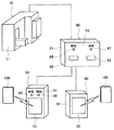
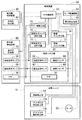
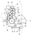
本発明ドアロック装置の第1実施形態を図1〜7に示す。図1は水平断面図、図2は図1のA−A線に沿って切断した垂直断面図、図3は錠前ユニットの内部機構の構成図、図4は図1と切断箇所を変えた水平断面図、図5はドアが閉じられた状態を示す図4と同様の水平断面図、図6はキーレスエントリー手段の検知と錠前ユニットの制御を司る制御装置の斜視図、図7は制御ブロック図である。 A first embodiment of the door lock device of the present invention is shown in FIGS. 1 is a horizontal cross-sectional view, FIG. 2 is a vertical cross-sectional view taken along line AA in FIG. 1, FIG. 3 is a configuration diagram of the internal mechanism of the lock unit, and FIG. FIG. 5 is a horizontal sectional view similar to FIG. 4 showing a state in which the door is closed, FIG. 6 is a perspective view of a control device for controlling the keyless entry means and controlling the lock unit, and FIG. 7 is a control block diagram. It is.
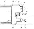
図1において、壁1に設けられたドア開口にはドア枠2がはめ込まれ、このドア枠2の中にドア3が設けられている。ドア3を閉じたときにこれを柔らかく受け止めるよう、ドア枠2にはゴムや軟質合成樹脂のような弾性体からなるクッション4が取り付けられている。
In FIG. 1, a
ドア枠2の内部には錠前ユニット10が固定される。ドア枠2にはドア3に対面する側面の2箇所に窓2a、2bが形成されており、この窓2a、2bから錠前ユニット10の筐体11の一部が露出する。窓2aは閉扉状態のドア3に整列する位置に設けられ、ここからデッドボルト12が出没する。窓2bはドア3を閉じたときに室内側になる位置に設けられ、ここからは後述するスライドつまみが突出する。
A
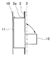
デッドボルト12は垂直面内で90゜回動する。デッドボルト12がドア3のボルト受け3aに係合すればドア3は開かなくなり、デッドボルト12がボルト受け3aから抜け出せばドア3を開けることが可能となる。筐体11の内部には、デッドボルト12が解錠状態にあることを検出するデッドボルト解錠検出部13aと、デッドボルト12が施錠状態にあることを検出するデッドボルト施錠検出部13bが配置される。デッドボルト解錠検出部13a及びデッドボルト施錠検出部13bはいずれもリミットスイッチにより構成される。
The
デッドボルト12を回動させるため、筐体11の中には図3に示す機構が配置されている。この機構において、デッドボルト12は軸20に回転不能に取り付けられ、軸20は歯車21に回転不能に連結されている。デッドボルト12の回動の動力源となるのはモータ22であり、その軸にはウォーム23が固定されている。ウォーム23と歯車21とを連結する動力伝達手段としての役割を果たすのは歯車列30である。なお歯車列30はモータ22の回転を減速して歯車21に伝える減速機構としての役割も担う。
In order to rotate the
歯車列30を構成するのは次の歯車群である。すなわちウォーム23にかみ合うウォーム歯車である第一歯車31、第1歯車31に固設されたピニオン31aにかみ合う第2歯車32、第2歯車32に固設されたピニオン32aにかみ合う第3歯車33、第3歯車33に固設されたピニオン33aにかみ合うとともに自身に固設されたピニオン34aに歯車21をかみ合わせる第4歯車34である。なお各歯車とそれに固設されたピニオンとは同軸関係にある。
The
第3歯車33はその前後の歯車、すなわち第2歯車32と第4歯車34を連結する位置(図3の実線位置)と、第2歯車32と第4歯車34の連結を解除する位置(図3の仮想線位置)との間を移動する。すなわち第3歯車33は第2歯車32と第4歯車34との間で動力伝達を断続するクラッチ手段として機能する。
The
第4歯車34には手動操作用のラック40がかみ合う。ラック40は筐体11の内部に垂直方向にスライドできるように保持されている。ラック40には窓2bを通じてドア枠2の外面に突き出すつまみ41が取り付けられる。ラック40とつまみ41が手動操作手段としての役割を果たす。
A
なおデッドボルト解錠検出部13aとデッドボルト施錠検出部13bをラック40のところに設け、ラック40の動きより解錠状態あるいは施錠状態を検出することも可能である。
It is also possible to provide the deadbolt unlocking
筐体11にはつまみ41を覆うカバー42が取り付けられる。カバー42は支点43を中心として水平面内で回動する。カバー42には周知のクリックモーション機構又はトグル機構が付設され、図1に実線で示す閉鎖状態又は仮想線で示す開放状態を自律的に保つように構成される。
A
第3歯車33はカバー42に連動して移動する。すなわち第3歯車33の軸とカバー42とは例えばコネクティングロッドのような連結機構で連結されており、カバー42が閉じると第3歯車33は図3の実線位置、すなわち第2歯車32と第4歯車34を連結する位置に移動し、カバー42が開くと第3歯車33は図3の仮想線位置、すなわち第2歯車32と第4歯車34の連結を解除する位置に移動する。
The
デッドボルト12には、ドア3が閉扉状態であるときのみデッドボルト12の回動を可能とするロック手段が設けられている。ロック手段を構成するのは歯車21と、軸51に揺動可能に支持され、歯車21の歯に係合して歯車21の回転を止めるラッチ50と、ラッチ50を歯車21への係合方向に付勢するばね52と、一端をラッチ50に当て、他端をドア枠2から突出させ、ドア枠2にドア3が入り込んだときにはドア3により押し込まれてラッチ50を歯車21から外れる方向に回動させるドア検出ロッド53である。
The
ドア検出ロッド53は水平に配置され、ドア枠2の窓2aから一端を突き出す。窓2aから突き出す方の端には、図4に見られるように、ドア3の角に向き合う斜面53aが形成されている。斜面53aにドア3の角が当たると斜面作用でドア検出ロッド53は筐体11の奥に押し込まれ、最終的には図5のようにドア3の端面に斜面53aの端が当たる形になる。この時ラッチ50はばね52の付勢力に抗して回動し、歯車21から離れている。
The
ドア3に対しては、それが閉扉状態であるときのみモータ22の駆動を可能とする閉扉検出部54が設けられる。閉扉検出部54を構成するのは検出ロッド53に組み合わせたマイクロスイッチである。マイクロスイッチは、そのアクチュエータがドア検出ロッド53に係合するように筐体11の内部に固定される。
The
錠前ユニット10の動作を司るのは図6に示す制御装置60である。制御装置60は室内側の壁面に固定される筐体61を有し、その中に後述する回路要素を収納している。筐体61の前面は操作パネル部62となっている。制御装置60には室内側検知装置80と室外側検知装置90が付属する。室内側検知装置80の筐体81は室内側の壁面に固定され、室外側検知装置90の筐体91は室外側の壁面に固定される。
The operation of the
室内側検知装置80及び室外側検知装置90の検知対象となるのはキーレスエントリー手段である無線ICカード100である。筐体81、91の前面には無線ICカード100をかざすときの位置の目安となる標識図形82、92が描かれている。
The detection target of the indoor
図7に制御装置60、室内側検知装置80、室外側検知装置90、及び錠前ユニット10のブロック構成を示す。制御装置60の中心になるのは中央制御部(CPU)63である。中央制御部63にはモータ22を駆動するモータ駆動回路64が接続される。モータ駆動回路64とモータ22の間には、モータ22に過電流が流れるのを監視する電流検出回路65が接続される。錠前ユニット10のデッドボルト解錠検出部13a、デッドボルト施錠検出部13b、及び閉扉検出部54も中央制御部63に接続されている。
FIG. 7 shows a block configuration of the
操作パネル部62には解錠表示ランプ66及び施錠表示ランプ67と、解錠スイッチ68及び施錠スイッチ69が配置される。解錠表示ランプ66及び施錠表示ランプ67には、例えば緑色と赤色といった具合に、異なる色の発光体(例えばLED)が用いられる。解錠スイッチ68及び施錠スイッチ69は押釦スイッチである。操作パネル部62にはブザー70も配置される。
On the
解錠表示ランプ66は解錠表示ランプ点灯回路71を介して、施錠表示ランプ67は施錠表示ランプ点灯回路72を介して、それぞれ中央制御部63に接続する。解錠スイッチ68は解錠スイッチ回路73を介して、施錠スイッチ69は施錠スイッチ回路74を介して、それぞれ中央制御部63に接続する。ブザー70はブザー鳴動回路75を介して中央制御部63に接続する。
The unlocking
室内側検知装置80は無線ICカード100と無線で情報をやりとりする室内側検知部83を備える。室内側検知部83はケーブルを介して中央制御部63に接続する。なお室内側検知装置80は制御装置60に一体化することもできる。
The indoor
室外側検知装置90は無線ICカード100と無線で情報をやりとりする室外側検知部93を備える。室外側検知部93はケーブルを介して中央制御部63に接続する。室外側検知装置90はこの他に解錠表示ランプ94及び施錠表示ランプ95とブザー96を備える。解錠表示ランプ94は解錠表示ランプ点灯回路71を介して、施錠表示ランプ95は施錠表示ランプ点灯回路72を介して、それぞれ中央制御部63に接続する。ブザー96はブザー鳴動回路75を介して中央制御部63に接続する。解錠表示ランプ94は解錠表示ランプ66と同色であり、施錠表示ランプ95は施錠表示ランプ67と同色である。
The outdoor
続いてドアロック装置の動作を説明する。まず、閉扉状態にあるドア3を室外側から解錠操作するところから話を始める。この時デッドボルト12は施錠位置(図3の実線位置)に下りており、デッドボルト施錠検出部13bがこれを検出している。カバー42は閉じた状態にあり、クラッチ手段である第3歯車33は第2歯車32と第4歯車34を連結する位置にある。すなわちクラッチは接続状態となっている。また閉扉状態のドア3がドア検出ロッド53を押しているのでラッチ50は歯車21から離れており、歯車21は回転可能である。さらに、閉扉検出部54のアクチュエータはドア検出ロッド53で押されて図3の破線位置にあり、ドア3が閉扉状態にあることを検出している。これを受けて中央制御部63はモータ22を駆動可能とする。
Next, the operation of the door lock device will be described. First, the talk is started from the
無線ICカード70を室外検知装置90に近づけるか、あるいは標識図形92のところに接触させると、無線ICカード70と室外側検知部93との間で無線により情報の伝達が行われ、室外側検知部93は解錠可との信号を中央制御部63に送る。中央制御部63はモータ22を解錠方向に回転させるようモータ駆動回路64に指令を出す。
When the
モータ22が解錠方向に回転すると、その回転は歯車列30を介して歯車21に伝えられ、デッドボルト12は図3の実線位置から仮想線位置へと90゜角度を変える。これによりデッドボルト12は錠前ユニット10の筐体11の中に収まり、ドア3は自由に開けられる状態になる。
When the
第4歯車34が回転するとラック40は垂直方向に移動し、つまみ41も垂直方向に動く。
When the
デッドボルト12が筐体11に収まったことをデッドボルト解錠検出部13aが検出した時点で、モータ22は回転を停止する。同時に操作パネル部62の解錠表示ランプ66及び室外側検知装置90の解錠表示ランプ94が点灯し、またブザー70及びブザー96が特定パターンの信号音を発し、ドア3が開けられる状態になったことを報知する。ドア3を開ければ点灯及び信号音発生は停止する。ドア3を開けなくても、所定時間が経過すれば中央制御部63のタイマー回路の働きで点灯及び信号音発生は停止する。
When the deadbolt unlocking
ドア3を開けるとドア検出ロッド53がドア3のあった位置へ突き出し、ラッチ50が歯車21に係合する。これにより、デッドボルト12は施錠位置に下りてこられなくなる。また閉扉検出部54がドア3の開扉を検出し、これを受けて中央制御部63がモータ22を駆動不能とするので、デッドボルト12には二重のロックがかかる。このため、デッドボルト12が施錠位置に突き出してドア3の閉扉を妨げるという事態は発生しない。
When the
ラッチ50が歯車21に係合した状態でモータ22に通電されるとモータ22が焼損するおそれがあるが、ドア3が開いた時点でモータ22への通電は禁止されるので、そのおそれもない。
If the
ドア3を閉めればドア検出ロッド53が押し込まれ、ラッチ50は歯車21を釈放する。また閉扉検出部54が閉扉を検出したことを受けて、中央制御部63がモータ22の駆動を可能とする。これにより、デッドボルト12を再びモータ22で施錠位置に回動させることが可能となる。
When the
デッドボルト12の施錠操作を室内側から行うときは、室内側検知装置80に無線ICカード100をかざす。すると無線ICカード100と室内側検知部83との間で無線により情報の伝達が行われ、室内側検知部83は中央制御部63に施錠可との信号を送る。中央制御部63はモータ22を施錠方向に回転させるようモータ駆動回路64に指令を出す。
When the
モータ22が施錠方向に回転すると、その回転は歯車列30を介して歯車21に伝えられ、デッドボルト12は図3の仮想線位置から実線位置へと90゜角度を変える。これによりデッドボルト12はドア3のボルト受け3aに係合し、ドア3は施錠される。
When the
デッドボルト12がボルト受け3aに係合したことをデッドボルト施錠検出部13bが検出した時点で、モータ22は回転を停止する。同時に操作パネル部62の施錠表示ランプ67及び室外側検知装置90の施錠表示ランプ95が点灯し、またブザー70及びブザー96が特定パターンの信号音を発し、ドア3が施錠されたことを報知する。所定時間経過後、中央制御部63のタイマー回路の働きで点灯及び信号音発生は停止する。
When the dead bolt locking
つまみ41は通常はカバー42で覆われており、ドア3に穴が明けられ、特殊解錠工具が差し込まれたとしても、特殊解錠工具でカバー42が開けられてつまみ41が操作されるようなことはない。
The
無線ICカード100の紛失、制御装置60の故障、あるいは停電などの理由により、モータ22を駆動して施錠・解錠操作を行うことができなくなったときでも、操作者が室内にいれば、手動操作で施錠・解錠操作を行うことが可能である。また、このような非常事態に限らず、室内側からは無線ICカード100を用いることなく施錠・解錠操作を行うことが可能である。以下これについて説明する。
Even if the
カバー42を開けるとそれに連動して第3歯車33が図3に仮想線で示す位置に移動する。これにより第2歯車32と第4歯車34の連結は断たれる。すなわちクラッチ切断状態となる。
When the
ここでつまみ41を動かしてラック40をスライドさせれば第4歯車34を回転させることができる。すなわちクラッチ手段より後段側に位置する歯車を手で回転させることができる。これにより、解錠位置に持ち上げられているデッドボルト12を手動で施錠位置に下ろし、また施錠位置に下りているデッドボルト12を手動で解錠位置に持ち上げることが可能になる。
If the
ドア3が開きさえすればラッチ50は歯車21に係合し、歯車21の回転を止める。従って、手動操作と言えども、ドア3が開いている状態でデッドボルト12を施錠状態にすることはできない。デッドボルト12の回動はあくまでもドア3が閉じているときのみ可能である。
As long as the
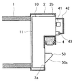
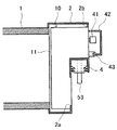
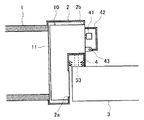
本発明ドアロック装置の第2実施形態を図8、9に示す。図8は水平断面図、図9はドアが閉じられた状態を示す図8と同様の水平断面図である。なお第2実施形態は多くの構成要素が第1実施形態と共通である。説明の重複を避けるため、第1実施形態と共通する構成要素には第1実施形態の説明で使用したのと同じ符号を付し、説明は省略する。第3実施形態についても同様とする。 A second embodiment of the door lock device of the present invention is shown in FIGS. 8 is a horizontal cross-sectional view, and FIG. 9 is a horizontal cross-sectional view similar to FIG. 8 showing the door closed. The second embodiment has many components in common with the first embodiment. In order to avoid duplication of explanation, the same reference numerals as those used in the explanation of the first embodiment are attached to the constituent elements common to the first embodiment, and the explanation is omitted. The same applies to the third embodiment.
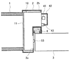
第2実施形態ではドア検出ロッド53の配置角度は第1実施形態と90゜異なり、クッション4の端面からドア検出ロッド53の端が突出する。クッション4にはドア検出ロッド53をスライド可能に挿通させる透孔(図示せず)が形成されている。ドア検出ロッド53は図9に示すようにドア3の室内側の面に当たって押し込まれる。
In the second embodiment, the arrangement angle of the
本発明ドアロック装置の第3実施形態を図10に示す。図10は錠前ユニットの内部機構の構成図である。 FIG. 10 shows a third embodiment of the door lock device of the present invention. FIG. 10 is a configuration diagram of the internal mechanism of the lock unit.
第3実施形態においては、つまみ41を覆うカバーがない。その代わりつまみ41はラック40に対し第1の位置と第2の位置をとり得るようになっている。つまみ41はラック40に対し、ラック40の移動方向と直交する方向に所定ストロークのスライドが可能であるように支持され、図示しないばねがつまみ41をドア枠2の外面に突き出す方向に付勢する。ばねの付勢力で突き出した位置が「第1の位置」であり、付勢力に抗して押し込まれた位置が「第2の位置」である。
In the third embodiment, there is no cover that covers the
第3歯車33は今度はつまみ41に連動して移動する。すなわち第3歯車33の軸とつまみ41とは例えばコネクティングロッドのような連結機構で連結されており、つまみ41が第1の位置にある間は第3歯車33は図10の実線位置、すなわち第2歯車32と第4歯車34を連結する位置にある。つまみ41を押し込むと、第3歯車33は図10の仮想線位置、すなわち第2歯車32と第4歯車34の連結を解除する位置に移動する。すなわちつまみ41が第1の位置をとったときクラッチ手段は接続状態となり、つまみ41が第2の位置をとったときクラッチ手段は切断状態となる。
The
このように突き出し位置が第1の位置、押し込み位置が第2の位置となるから、きわめて操作しやすい。また、つまみ41を単に上下に動かそうとしただけではつまみ41は動かないから、カバーがないにもかかわらず、特殊解錠工具でつまみ41を動かされることを防止できる。
Since the protruding position is the first position and the pushing position is the second position in this way, the operation is extremely easy. Moreover, since the
第1実施形態の場合、つまみ41に指をかけるためには必ずカバー42を開けねばならない。従って、クラッチを切らずにラック40を手動で動かすということはあり得なかった。これに対し第3実施形態の場合、クラッチ接続状態のまま、すなわち第2歯車32と第4歯車34を第3歯車33が連結した状態のままでも、つまみ41を上下に動かそうという試み自体は可能である。しかしながらクラッチ手段より前段側にウォームとウォーム歯車(ウォーム23と第1歯車31)の組み合わせが存在するので、ウォーム歯車機構のセルフロック機能のため、クラッチ手段より後段側、すなわちラック40の側から歯車列30を回転させることはできない。このため、デッドボルト12を手動操作すべきでない局面でデッドボルト12が手動操作されるということがない。
In the case of the first embodiment, in order to put a finger on the
以上本発明の各実施形態につき説明したが、この他、発明の主旨を逸脱しない範囲で種々の変更を加えて実施することができる。 While the embodiments of the present invention have been described above, various modifications can be made without departing from the spirit of the invention.
本発明は、建物のドアロックシステムに広く利用可能である。 The present invention is widely applicable to building door lock systems.
1 壁
2 ドア枠
3 ドア
3a ボルト受け
10 錠前ユニット
11 筐体
12 デッドボルト
22 モータ
30 歯車列(動力伝達手段)
33 第3歯車(クラッチ手段)
40 ラック
41 つまみ
50 ラッチ
52 ばね
53 ドア検出ロッド
54 閉扉検出部
60 制御装置
80 室内側検知装置
90 室外側検知装置
100 無線ICカード(キーレスエントリー手段)
DESCRIPTION OF
33 Third gear (clutch means)
40
Claims (13)
(a)ドア枠に固定される筐体
(b)垂直面内で回動して前記筐体から出没し、ドアに設けられたボルト受けに係合してドアの閉扉状態を保ち、このボルト受けから抜け出したときはドアの開扉を可能とするデッドボルト
(c)前記デッドボルトの回動の動力源となるモータ
(d)前記モータと前記デッドボルトとを連結する動力伝達手段
(e)前記動力伝達手段に付設されたクラッチ手段
(f)前記クラッチ手段が前記モータからデッドボルトへの動力伝達を断ったとき、モータに代わってデッドボルトを回動させる手動操作手段。 A door lock device for keeping the door closed is characterized by using a lock unit having the following configuration:
(A) Housing fixed to the door frame (b) Rotating in a vertical plane, protruding and retracting from the housing, and engaging with a bolt receiver provided on the door to keep the door closed, this bolt A dead bolt that enables the door to be opened when the door is pulled out (c) a motor that is a power source for turning the dead bolt (d) a power transmission means (e) that connects the motor and the dead bolt Clutch means attached to the power transmission means (f) Manual operation means for rotating the dead bolt instead of the motor when the clutch means cuts off the power transmission from the motor to the dead bolt.
Priority Applications (1)
| Application Number | Priority Date | Filing Date | Title |
|---|---|---|---|
| JP2004110833A JP3946204B2 (en) | 2004-04-05 | 2004-04-05 | Door lock device |
Applications Claiming Priority (1)
| Application Number | Priority Date | Filing Date | Title |
|---|---|---|---|
| JP2004110833A JP3946204B2 (en) | 2004-04-05 | 2004-04-05 | Door lock device |
Publications (2)
| Publication Number | Publication Date |
|---|---|
| JP2005290921A true JP2005290921A (en) | 2005-10-20 |
| JP3946204B2 JP3946204B2 (en) | 2007-07-18 |
Family
ID=35324161
Family Applications (1)
| Application Number | Title | Priority Date | Filing Date |
|---|---|---|---|
| JP2004110833A Expired - Fee Related JP3946204B2 (en) | 2004-04-05 | 2004-04-05 | Door lock device |
Country Status (1)
| Country | Link |
|---|---|
| JP (1) | JP3946204B2 (en) |
Cited By (7)
| Publication number | Priority date | Publication date | Assignee | Title |
|---|---|---|---|---|
| JP2008057179A (en) * | 2006-08-30 | 2008-03-13 | Miwa Lock Co Ltd | Detector for locking and unlocking operation frequency |
| CN108757854A (en) * | 2018-07-20 | 2018-11-06 | 深圳市罗曼斯科技有限公司 | A kind of gearbox |
| CN108823915A (en) * | 2018-07-27 | 2018-11-16 | 乔坤 | A kind of Clothes treatment device |
| CN108868344A (en) * | 2018-06-29 | 2018-11-23 | 全民认证科技(杭州)有限公司 | A kind of non-embedded remote monitoring intelligent door lock |
| CN109253214A (en) * | 2018-10-29 | 2019-01-22 | 深圳市罗曼斯科技有限公司 | A kind of emergency gearbox |
| CN110219545A (en) * | 2019-07-13 | 2019-09-10 | 深圳市龙电兴业科技有限公司 | Intelligent secret room door |
| JP2020183679A (en) * | 2019-05-09 | 2020-11-12 | 株式会社熊平製作所 | Closing device for nuclear power facility |
-
2004
- 2004-04-05 JP JP2004110833A patent/JP3946204B2/en not_active Expired - Fee Related
Cited By (10)
| Publication number | Priority date | Publication date | Assignee | Title |
|---|---|---|---|---|
| JP2008057179A (en) * | 2006-08-30 | 2008-03-13 | Miwa Lock Co Ltd | Detector for locking and unlocking operation frequency |
| CN108868344A (en) * | 2018-06-29 | 2018-11-23 | 全民认证科技(杭州)有限公司 | A kind of non-embedded remote monitoring intelligent door lock |
| CN108868344B (en) * | 2018-06-29 | 2020-11-13 | 全民认证科技(杭州)有限公司 | Non-embedded remote monitoring intelligent door lock |
| CN108757854A (en) * | 2018-07-20 | 2018-11-06 | 深圳市罗曼斯科技有限公司 | A kind of gearbox |
| CN108757854B (en) * | 2018-07-20 | 2024-04-23 | 深圳市罗漫斯智能家居有限公司 | Gear box |
| CN108823915A (en) * | 2018-07-27 | 2018-11-16 | 乔坤 | A kind of Clothes treatment device |
| CN109253214A (en) * | 2018-10-29 | 2019-01-22 | 深圳市罗曼斯科技有限公司 | A kind of emergency gearbox |
| CN109253214B (en) * | 2018-10-29 | 2023-09-08 | 深圳市罗漫斯智能家居有限公司 | Emergency gearbox |
| JP2020183679A (en) * | 2019-05-09 | 2020-11-12 | 株式会社熊平製作所 | Closing device for nuclear power facility |
| CN110219545A (en) * | 2019-07-13 | 2019-09-10 | 深圳市龙电兴业科技有限公司 | Intelligent secret room door |
Also Published As
| Publication number | Publication date |
|---|---|
| JP3946204B2 (en) | 2007-07-18 |
Similar Documents
| Publication | Publication Date | Title |
|---|---|---|
| US5626039A (en) | Electronic safety-lock | |
| JP5524781B2 (en) | Door closer equipment | |
| JP4625092B2 (en) | Elevator door safety lock for detecting intrusion into shaft through landing door and elevator equipped with the safety lock | |
| JP2009024450A (en) | Door lock device | |
| JP3946204B2 (en) | Door lock device | |
| KR101145971B1 (en) | Digital locking device for window | |
| JP5818468B2 (en) | Electric lock | |
| CN109881988B (en) | Lockset with emergency unlocking structure | |
| CN210032953U (en) | Dual-control system suitable for intelligent lockset | |
| JP5351822B2 (en) | Sliding door device with electric lock | |
| JP2008133656A (en) | Electric lock | |
| JP5108626B2 (en) | Door device | |
| CN209924644U (en) | Electric lock body with improved structure | |
| CN110056254B (en) | Structure improved electric lock body | |
| CN210422194U (en) | Lockset with emergency unlocking structure | |
| JP4702682B2 (en) | Thumb turn device | |
| JP2009074320A (en) | Opening section equipment | |
| JP2004250955A (en) | Device for locking/unlocking sliding door of cabinet | |
| KR200289539Y1 (en) | A digital doorlock | |
| JP2006233658A (en) | Locking device for game machine | |
| JP2005162481A (en) | Automatic lock type elevator brake | |
| JP2004244899A (en) | Door opening holding device | |
| JPS58178784A (en) | Automatic door opening and closing apparatus in automobile | |
| JP4253769B2 (en) | System switch with self-holding function | |
| JP2009030283A (en) | Door locking device |
Legal Events
| Date | Code | Title | Description |
|---|---|---|---|
| A131 | Notification of reasons for refusal |
Free format text: JAPANESE INTERMEDIATE CODE: A131 Effective date: 20070116 |
|
| A521 | Written amendment |
Free format text: JAPANESE INTERMEDIATE CODE: A523 Effective date: 20070316 |
|
| TRDD | Decision of grant or rejection written | ||
| A01 | Written decision to grant a patent or to grant a registration (utility model) |
Effective date: 20070410 Free format text: JAPANESE INTERMEDIATE CODE: A01 |
|
| A61 | First payment of annual fees (during grant procedure) |
Free format text: JAPANESE INTERMEDIATE CODE: A61 Effective date: 20070410 |
|
| R150 | Certificate of patent (=grant) or registration of utility model |
Free format text: JAPANESE INTERMEDIATE CODE: R150 |
|
| FPAY | Renewal fee payment (prs date is renewal date of database) |
Free format text: PAYMENT UNTIL: 20100420 Year of fee payment: 3 |
|
| FPAY | Renewal fee payment (prs date is renewal date of database) |
Free format text: PAYMENT UNTIL: 20130420 Year of fee payment: 6 |
|
| LAPS | Cancellation because of no payment of annual fees |