JP2005290529A - Valve, manufacturing method thereof, power plant using the same, and valve member - Google Patents
Valve, manufacturing method thereof, power plant using the same, and valve member Download PDFInfo
- Publication number
- JP2005290529A JP2005290529A JP2004111669A JP2004111669A JP2005290529A JP 2005290529 A JP2005290529 A JP 2005290529A JP 2004111669 A JP2004111669 A JP 2004111669A JP 2004111669 A JP2004111669 A JP 2004111669A JP 2005290529 A JP2005290529 A JP 2005290529A
- Authority
- JP
- Japan
- Prior art keywords
- valve
- base alloy
- less
- alloy
- cobalt
- Prior art date
- Legal status (The legal status is an assumption and is not a legal conclusion. Google has not performed a legal analysis and makes no representation as to the accuracy of the status listed.)
- Granted
Links
Images
Landscapes
- Sliding Valves (AREA)
- Pressure Welding/Diffusion-Bonding (AREA)
- Manufacture Of Metal Powder And Suspensions Thereof (AREA)
- Powder Metallurgy (AREA)
Abstract
【課題】
本発明の目的は、より高硬度及び高耐衝撃性を有する弁とその製造方法及びそれを用いた発電プラント並びに弁用部材を提供することにある。
【解決手段】
本発明は、弁体と弁箱とを備え、互いに摺動する弁座表面に、基地中にクロム炭化物が分散したコバルト基合金部材、ニッケル基合金部材及び鉄基合金部材から選ばれた1種が形成されている弁において、前記部材は静水圧加圧焼結又は熱間押出し焼結によって形成され、前記弁座に拡散接合されていることを特徴とする。
【選択図】図1
【Task】
An object of the present invention is to provide a valve having higher hardness and higher impact resistance, a manufacturing method thereof, a power plant using the same, and a valve member.
[Solution]
The present invention comprises a valve body and a valve box, and on a valve seat surface that slides on one another, one type selected from a cobalt base alloy member, a nickel base alloy member, and an iron base alloy member in which chromium carbide is dispersed in the base The member is formed by hydrostatic pressure sintering or hot extrusion sintering, and is diffusion bonded to the valve seat.
[Selection] Figure 1
Description
本発明は、高硬度及び高耐衝撃性を有する新規な弁とその製造方法及びそれを用いた火力発電プラント、原子力発電プラント並びに弁用部材に関する。 The present invention relates to a novel valve having high hardness and high impact resistance, a manufacturing method thereof, a thermal power plant using the same, a nuclear power plant, and a valve member.
従来、各種の流体機械、化学プラント、火力プラントあるいは原子力プラントに使用される安全弁、玉型弁、仕切り弁、逆止弁、制御弁、逃し弁あるいはちょう型弁などには、弁座の表面にステライトと呼ばれるコバルト基合金が肉盛溶接されたものが使用されてきた。弁は、摩耗しにくいこと、焼き付きを生じにくいこと、又、かじりを生じにくいこと、エロージョンを生じにくいことも必要である。又、耐食性も高い方がよい。 Conventionally, a safety valve, a ball valve, a gate valve, a check valve, a control valve, a relief valve or a butterfly valve used in various fluid machinery, chemical plants, thermal power plants or nuclear power plants has a valve seat surface. An overlaid welded cobalt-based alloy called stellite has been used. The valve also needs to be less likely to wear, less likely to seize, less likely to cause galling, and less likely to cause erosion. In addition, it is better that the corrosion resistance is high.
しかし、近年、タービン発電設備等では循環水の水質調整のために循環水系統に過酸化水素水等の薬剤が注入されるようになり、薬剤の注入点より下流の溶存酸素量が増加し、その結果、弁の弁座面等にエロージョン、かじりによる損傷が発生している。これは弁の弁座部に肉盛されているコバルト基合金等の網目状クロム炭化物が選択的に腐食損傷するためである。高速流体中ではクロム炭化物の腐食損傷に続いて、鋳造組織の基地部(マトリックス)が脱落し、エロージョンが発生する場合がある。 However, in recent years, in turbine power generation facilities and the like, chemicals such as hydrogen peroxide water have been injected into the circulating water system to adjust the quality of the circulating water, and the amount of dissolved oxygen downstream from the injection point of the chemical has increased. As a result, the valve seat surface of the valve is damaged by erosion and galling. This is because reticulated chromium carbide such as a cobalt-based alloy built up on the valve seat portion of the valve is selectively corroded. In the high-speed fluid, the base portion (matrix) of the cast structure may fall off following the corrosion damage of the chromium carbide, and erosion may occur.
また、原子力発電設備においても、炉水と接する摺動部及び炉内に冷却水を供給する系統設備の弁類に上述の事象が発生する可能性があり、これらの部位に肉盛されているコバルト基合金は、腐食・エロージョンによって系統中に混入し、さらにこれらの流出したコバルトが原子炉内で放射化し半減期の長いコバルト同位体となって系統設備の放射線量を増加させる可能性がある。 Moreover, in the nuclear power generation facilities, the above-mentioned event may occur in the sliding portion in contact with the reactor water and the valves of the system facility for supplying the cooling water to the reactor, and these parts are overlaid. Cobalt-based alloys may be mixed into the system due to corrosion and erosion, and these spilled cobalt may be activated in the reactor and become a cobalt isotope with a long half-life, increasing the radiation dose of the system equipment. .
これらの問題点に対し、特許文献1では、クロム炭化物が粒径30μm以下の粒状又は塊状に微細化されているコバルト基合金を弁座面に形成することにより、腐食損傷等が生じにくくなり、弁の寿命延長が図れることが示されている。 With respect to these problems, in Patent Document 1, it is difficult to cause corrosion damage or the like by forming on the valve seat surface a cobalt-based alloy in which chromium carbide is refined in a granular or lump shape with a particle size of 30 μm or less, It has been shown that the life of the valve can be extended.
しかし、特許文献1の方法は、仕切り弁のような「すべり摩耗」を伴う弁では有効であるが、特に逆止弁や安全弁のような「衝撃摩耗」を伴う弁では必ずしも十分でなく、さらに高硬度及び高耐衝撃性の弁座が求められている。 However, although the method of Patent Document 1 is effective for a valve with “slip wear” such as a gate valve, it is not always sufficient for a valve with “impact wear” such as a check valve or a safety valve. A valve seat with high hardness and high impact resistance is required.
本発明の目的は、より高硬度及び高耐衝撃性を有する弁とその製造方法及びそれを用いた発電プラント並びに弁用部材を提供することにある。 An object of the present invention is to provide a valve having higher hardness and higher impact resistance, a manufacturing method thereof, a power plant using the same, and a valve member.
本発明は、粉末冶金法を用いて、粒状・塊状のクロム炭化物をより微細化し、最大粒径10μm以下、平均粒径5μm以下とし、より高硬度でしかも耐衝撃性を有する弁にある。 The present invention resides in a valve having a higher hardness and impact resistance, by using a powder metallurgy method to further refine the granular and massive chromium carbide to have a maximum particle size of 10 μm or less and an average particle size of 5 μm or less.
即ち、通常の溶解によって網目状に形成される巨大なクロム炭化物を、粉末冶金法によって微細な不連続の粒状又は塊状にすることにより、より大量のクロム炭化物を含有させても熱間塑性加工を施すことができることにより、より高硬度でしかも耐衝撃性を大幅に改善できる。特にクロム炭化物の最大粒径を10μm以下及び平均粒径を5μm以下、好ましくは0.5〜5μmとすることにより、高硬度・高靱性・高耐食性を同時に兼ね備えた弁座を得ることができる。 That is, by forming a large amount of chromium carbide formed into a mesh by normal melting into fine discontinuous grains or lumps by powder metallurgy, hot plastic working can be performed even if a larger amount of chromium carbide is contained. By being able to be applied, it is possible to significantly improve the impact resistance with higher hardness. In particular, by setting the maximum particle diameter of chromium carbide to 10 μm or less and the average particle diameter to 5 μm or less, preferably 0.5 to 5 μm, a valve seat having high hardness, high toughness, and high corrosion resistance can be obtained at the same time.
特に、コバルト基合金においては、クロム炭化物を金属ミクロ組織の基地中により微細に粒状・塊状に分散させるためには、真空溶解したインゴットを熱間プレス、熱間加工することによっても可能であるが、この方法では平均粒径を5μm以下とすることは困難である。また、硬さは主に炭素(C)含有量に依存するが、C含有量を高めたインゴットを熱間加工すると、加工中に割れが発生しやすくなり、健全な板、棒材を作製するのが困難であり、より靱性を高めることができない。 In particular, in a cobalt-based alloy, in order to disperse chromium carbide in a finer form in a matrix of a metal microstructure, it is possible to hot-press and hot-work a vacuum-melted ingot. In this method, it is difficult to make the average particle size 5 μm or less. In addition, the hardness depends mainly on the carbon (C) content, but if an ingot with increased C content is hot-worked, cracking is likely to occur during processing, and a sound plate or bar is produced. It is difficult to improve toughness.
クロム炭化物の平均粒径を5μm以下にするためには、粉末冶金プロセスを用いるのが好ましいが、その粉末の粒径をより細粒に形成することによって得られる。すなわち、非酸化性ガスアトマイズ法により製造された多量のCr炭化物を含むコバルト基合金、ニッケル基合金及び鉄基合金の粉末はその粒径を所望の大きさに形成し、静水圧焼結(HIP:Hot Isostatic Press)処理あるいは粉末熱間押出加工でち密化する。この平均粒径が5μm以下のクロム炭化物を有するち密化後の合金部材は、より多量のクロム炭化物を含有させることができ、さらに熱間圧延、熱間鍛造又は熱間据え込み加工を行うことができるため、高硬度でしかも耐衝撃性及び靱性を一層向上させることができる。従って、C含有量を高めた合金粉末を用いても、割れが発生しにくく、健全な板、棒材を得ることができる。 In order to make the average particle diameter of chromium carbide 5 μm or less, it is preferable to use a powder metallurgy process, but it can be obtained by forming the particle diameter of the powder into finer particles. That is, powders of cobalt-base alloy, nickel-base alloy, and iron-base alloy containing a large amount of Cr carbide produced by a non-oxidizing gas atomization method have a desired particle size, and hydrostatic pressure sintering (HIP: Hot isostatic press) or compacted by hot powder extrusion. The densified alloy member having chromium carbide having an average particle size of 5 μm or less can contain a larger amount of chromium carbide, and can be further subjected to hot rolling, hot forging, or hot upsetting. Therefore, the impact resistance and toughness can be further improved with high hardness. Therefore, even if an alloy powder with an increased C content is used, cracks are unlikely to occur and a sound plate or bar can be obtained.
平均粒径5μm以下の微細なクロム炭化物を有する合金部材は、炭素鋼又は低合金鋼又はステンレス鋼からなる弁座基材に拡散接合によって接合されることが望ましい。特に液相拡散接合によって接合されることが望ましい。又、液相拡散接合を行う場合には、珪素及びホウ素を含有するニッケル基合金からなるインサート材を、弁座基材と粒状又は塊状のクロム炭化物を有するCo基合金との間にはさんで接合を行うことが望ましい。 The alloy member having fine chromium carbide having an average particle size of 5 μm or less is desirably joined by diffusion bonding to a valve seat base made of carbon steel, low alloy steel or stainless steel. It is particularly desirable to join by liquid phase diffusion bonding. When liquid phase diffusion bonding is performed, an insert material made of a nickel-based alloy containing silicon and boron is sandwiched between a valve seat base material and a Co-based alloy having granular or massive chromium carbide. It is desirable to perform bonding.
拡散接合以外の接合方法として、アーク溶接のように溶融させて接合する方法では、溶融によってクロム炭化物が網目状の連続した状態に戻ってしまうので不適当である。ろう付けによる方法は、コバルト基合金の溶融を伴わないが、接合部の強度が低いので不適当である。 As a bonding method other than diffusion bonding, a method of melting and bonding as in arc welding is not appropriate because the chromium carbide returns to a continuous network state by melting. The method by brazing does not involve melting of the cobalt-based alloy, but is inappropriate because the strength of the joint is low.
即ち、本発明は、弁体と弁箱とを備え、互いに摺動する弁座表面に、基地中にクロム炭化物が分散したコバルト基合金部材、ニッケル基合金部材及び鉄基合金部材から選ばれた1種が形成されている弁において、前記部材は静水圧加圧焼結又は熱間押出し焼結によって形成され、前記弁座に拡散接合されていることを特徴とする弁にある。溶解によって基地中に網目状に形成される巨大なクロム炭化物は、粉末にすることによって分断され、更に、熱間圧延、熱間鍛造又は熱間据え込み加工によって四方に分断される結果、部材全体で平均粒径が5μm以下の均一なクロム炭化物が得られる。 That is, the present invention is selected from a cobalt base alloy member, a nickel base alloy member, and an iron base alloy member in which chromium carbide is dispersed in a base on a valve seat surface that includes a valve body and a valve box and slides on each other. In the valve in which one kind is formed, the member is formed by hydrostatic pressure sintering or hot extrusion sintering, and is diffusion bonded to the valve seat. The huge chromium carbide formed in the network in the base by melting is divided into powders, and further divided into four parts by hot rolling, hot forging or hot upsetting, resulting in the whole member A uniform chromium carbide having an average particle size of 5 μm or less is obtained.
前記部材は、静水圧加圧焼結又は熱間押出し焼結後、熱間据え込み加工が施され、前記クロム炭化物の平均粒径が5μm以下であることが好ましい。 The member is preferably subjected to hot upsetting after hydrostatic pressure sintering or hot extrusion sintering, and the average particle size of the chromium carbide is preferably 5 μm or less.
前記コバルト基合金が重量でC 1.0〜3.5%、Si 2%以下、Cr 25〜35%、W 15%以下、Fe 3%以下、Ni 3%以下、Mo 6%以下を含み、残部がCo及び不可避不純物からなり、前記ニッケル基合金が重量でC 1%以下、Si 7%以下、Cr 7〜20%、W 5%以下、B 3.5%以下を含み、残部がNiからなり、前記鉄基合金が重量でC 1.5%以下、Si 4%以下、Cr 15〜27%、Mo 8%以下を含み、残部がFe及び不可避不純物からなることが好ましい。特に、コバルト基合金がC 1.2〜2.0%、Si 0.5〜2%、Cr 28〜32%、W 3〜8%、Fe 0.3〜1.5%、Ni 0.5〜3%、Mo 5%以下を含む合金、前記ニッケル基合金がC 0.2〜1%、Si 2〜7%、Cr 10〜20%、W 1〜5%、B 1〜3.5%を含む合金、前記鉄基合金がC 0.5〜1.5%、Si 1〜4%、Cr 20〜27%、Mo 1〜8%を含む合金が好ましい。
The cobalt-based alloy contains C 1.0-3.5% by weight, Si 2% or less, Cr 25-35%,
又、前記合金部材は、ビッカース硬さ(Hv)が400以上であること、Uノッチ衝撃値が5J/cm2 以上であること、前記弁体及び前記弁箱が、炭素鋼、低合金鋼又はステンレス鋼よりなること、弁として逃がし安全弁(SRV:Safety Relief Valve)において好適である。 The alloy member has a Vickers hardness (Hv) of 400 or more, a U-notch impact value of 5 J / cm 2 or more, and the valve body and the valve box are made of carbon steel, low alloy steel or It is made of stainless steel, and is suitable as a safety relief valve (SRV) as a valve.
本発明は、弁体と弁箱とを備え、互いに摺動する弁座表面に、基地中にクロム炭化物が分散したコバルト基合金部材、ニッケル基合金部材及び鉄基合金部材から選ばれた1種を形成する弁の製造方法において、前記部材を静水圧加圧焼結又は熱間押出し焼結によって形成し、次いで前記弁座に拡散接合することを特徴とする弁の製造方法にある。 The present invention comprises a valve body and a valve box, and on a valve seat surface that slides on one another, one type selected from a cobalt base alloy member, a nickel base alloy member, and an iron base alloy member in which chromium carbide is dispersed in the base In the method for manufacturing a valve, the member is formed by hydrostatic pressure sintering or hot extrusion sintering, and then diffusion bonded to the valve seat.
又、本発明は、弁体と弁箱とを備え、互いに摺動する弁座表面に、基地中にクロム炭化物が分散したコバルト基合金部材、ニッケル基合金部材及び鉄基合金部材から選ばれた1種を形成する弁の製造方法において、前記部材を前記コバルト基合金、ニッケル基合金及び鉄基合金から選ばれた1種よりなる合金粉末を静水圧加圧焼結又は熱間押出し焼結後、熱間圧延、熱間鍛造又は熱間据え込み加工によって形成し、次いで前記弁座に拡散接合することを特徴とする弁の製造方法にある。 Further, the present invention is selected from a cobalt base alloy member, a nickel base alloy member, and an iron base alloy member in which chromium carbide is dispersed in a base on a valve seat surface that includes a valve body and a valve box and slides on each other. In the method of manufacturing a valve forming one type, the member is made of an alloy powder consisting of one type selected from the cobalt base alloy, nickel base alloy and iron base alloy after hydrostatic pressure sintering or hot extrusion sintering The valve manufacturing method is characterized by forming by hot rolling, hot forging or hot upsetting, and then diffusion bonding to the valve seat.
前記静水圧加圧焼結又は熱間押出し焼結は、前記合金粉末を金属カプセルに充填封入し、静水圧加圧加熱又は熱間押出し加工であること、前記拡散接合は、前記部材と弁座との間に前記弁座、弁体及び弁箱の融点よりも低融点のインサート材を介在させて、該インサートの融点以上の温度で加熱保持する液相拡散接合であること、前記前記合金粉末を非酸化性ガスアトマイズ法により製造することが好ましい。 The hydrostatic pressure sintering or hot extrusion sintering is performed by filling and encapsulating the alloy powder in a metal capsule, hydrostatic pressure heating or hot extrusion, and the diffusion bonding includes the member and the valve seat. The alloy powder is a liquid phase diffusion bonding in which an insert material having a melting point lower than the melting point of the valve seat, the valve body and the valve box is interposed therebetween and heated and held at a temperature equal to or higher than the melting point of the insert. Is preferably produced by a non-oxidizing gas atomization method.
インサート材には、ホウ素(B)、珪素(Si)あるいはリン(P)等の融点降下元素を含むものを使用するのが望ましい。B、Si、P等の融点降下元素を被接合材中に拡散させることで、固相拡散接合に比較して接合時の加圧力を小さくでき、接合による変形を少なく抑えることができる。また、接合面の機械仕上げ精度もRmax10μm程度にでき、良好な接合面を得ることができる。
It is desirable to use an insert material containing a melting point lowering element such as boron (B), silicon (Si) or phosphorus (P). By diffusing melting point lowering elements such as B, Si, and P into the material to be joined, the pressure applied during joining can be reduced as compared with solid phase diffusion joining, and deformation due to joining can be reduced. Also, the machine finishing accuracy of the joint surface can be set to about
好適なインサート材は、重量で、Si 1〜8%、B 1〜5%を含むニッケル基合金からなるもの、又は、Si 1〜8%、B 1〜5%及びCr 5〜20%を含むニッケル基合金からなるものである。更に好適には、重量で、Si 3.5〜5.5%及びB 2.0〜4.0%を含むニッケル基合金、Cr6〜15%、Si 3.5〜5.5%及びB 2.0〜4.0%を含むニッケル基合金、及びP 10〜14%を含むニッケル基合金から選ばれた合金が好ましい。弁座の基材には、炭素鋼、低合金鋼またはステンレス鋼を用いることができる。
Suitable inserts consist of a nickel-base alloy containing 1 to 8% Si and 1 to 5% B by weight, or contain 1 to 8% Si, 1 to 5% B and 5 to 20% Cr It consists of a nickel-based alloy. More preferably, by weight, a nickel-base alloy containing 3.5-5.5% Si and 2.0-4.0% B, a nickel-base alloy containing 6-15% Cr, 3.5-5.5% Si and 2.0-4.0% B, and
水蒸気及び高温水が循環する循環系統を有する火力発電プラント又は原子力発電プラントにおいて、前記循環系統内に配置された弁が、前述に記載の弁によって構成される。 In a thermal power plant or a nuclear power plant having a circulation system in which water vapor and high-temperature water circulate, a valve disposed in the circulation system is configured by the valve described above.
本発明は、弁体と弁箱が互いに摺動する弁座表面に形成される弁用部材において、クロム炭化物が分散したコバルト基合金部材、ニッケル基合金部材及び鉄基合金部材から選ばれた1種からなり、前記部材は据え込み熱間加工又は熱間静水圧加圧加工が施されていることを特徴とする弁用部材にある。 The present invention is a valve member formed on a valve seat surface on which a valve body and a valve box slide relative to each other, and is selected from a cobalt base alloy member, a nickel base alloy member and an iron base alloy member in which chromium carbide is dispersed 1 It consists of seed | species, The said member exists in the member for valves characterized by the upset hot working or the hot isostatic pressing process being performed.
本発明によれば、より高硬度及び高耐衝撃性を有する弁とその製造方法及びそれを用いた発電プラント並びに弁用部材を提供することができる。 ADVANTAGE OF THE INVENTION According to this invention, the valve | bulb which has higher hardness and high impact resistance, its manufacturing method, a power plant using the same, and the member for valves can be provided.
以下、本発明を実施するための最良の形態を具体的な実施例によって説明するが、本発明はこれらの実施例に限定されるものではない。 Hereinafter, the best mode for carrying out the present invention will be described by way of specific examples, but the present invention is not limited to these examples.
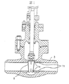
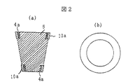
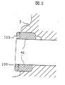
図1は、本発明に係る仕切り弁の断面図であり、図2は(a)が仕切り弁の弁体の拡大断面図、(b)が弁体の(a)の側面図、図3が弁箱の弁体への接触部近傍の拡大図である。仕切り弁は、弁体5と弁箱3を有し、両者の摺動面に弁座1a、1bを有する。弁体5は円盤状で、仕切り弁の形状に沿って上が下よりやや厚い傾斜した形状を有し、弁座1aは、図2(a)に示す弁座シート4aに図2(b)に示すコバルト基合金リング10aが弁体5の本体より1mm程度突出した状態で構成されている。弁箱3の弁座1bは、弁座シート4bとコバルト基合金リング10bとから構成され、弁体5が接触する部分で弁体5に添って傾斜した形状を有する。
1 is a cross-sectional view of a gate valve according to the present invention, FIG. 2 is an enlarged cross-sectional view of a valve body of the gate valve, (b) is a side view of (a) of the valve body, and FIG. It is an enlarged view of the contact part vicinity to the valve body of a valve box. The gate valve has a valve body 5 and a
本実施例では、溶存酸素雰囲気下で使用される仕切り弁を以下の方法によって製造した。化学組成が重量で、C 1.34%−Si 1.1%−Cr 30.3%−W 4.6%−Fe 0.6%−Ni 1.1%−Mo 0.1%を含むコバルト基合金の合金粉末をArガスアトマイズ法により形成した。この合金粉末はほぼ球形であり、粉末粒径:70〜250meshの大きさに選別して、炭素鋼製のカプセルに充填し、真空脱気後に、950℃で1時間、2000気圧の加圧下の静水圧加圧焼結(HIP)処理を行い、直径125mm、長さ110mmの円柱形状を得た。更に、HIP処理後に据込み熱間鍛造を行い、長さを110mmから40mmまで据込む熱間加工して、クロム炭化物の平均粒径が5μm以下であるコバルト基合金の円盤を得た。このコバルト基合金から削り出した厚さ5mmのコバルト基合金リング10aを、弁体5側の弁座シート4aにインサート材を間に挟んで押付けた。また、コバルト基合金から削り出した厚さ5mmのコバルト基合金リング10bを、弁箱3側の弁座シート4bにインサート材を間に挟んで押付けた。そして、下記に示す条件で液相拡散接合を行った。
In this example, a gate valve used in a dissolved oxygen atmosphere was manufactured by the following method. An alloy powder of a cobalt base alloy containing, by weight, C 1.34% -Si 1.1% -Cr 30.3% -W 4.6% -Fe 0.6% -Ni 1.1% -Mo 0.1% was formed by an Ar gas atomization method. This alloy powder is almost spherical, and is selected into a particle size of 70 to 250 mesh, filled into a carbon steel capsule, and after vacuum degassing, at 950 ° C. for 1 hour under a pressure of 2000 atmospheres. Hydrostatic pressure sintering (HIP) treatment was performed to obtain a cylindrical shape having a diameter of 125 mm and a length of 110 mm. Furthermore, upsetting hot forging was performed after HIP treatment, and hot working up to a length of 110 mm to 40 mm was performed to obtain a cobalt-based alloy disk having an average particle size of chromium carbide of 5 μm or less. The 5 mm-thick cobalt base alloy ring 10a cut out from this cobalt base alloy was pressed against the valve seat sheet 4a on the valve body 5 side with an insert material in between. Further, a 5 mm thick cobalt
弁座シート(基材)4a及び4bはいずれも、SCPH2(S25C相当)の鋳物である。インサート材は、重量で、Si 4.5とB 3.2%を含み、残部がNiからなるニッケル基合金よりなり、厚さは約40μmの箔である。インサート材の固相線温度は約980℃、液相線温度は約1040℃である。液相拡散接合は、接合温度:1070℃、保持時間:1時間、真空度:2×10⁻⁴Torr、加圧力:80g/cm2の条件で行った。インサート材には、融点降下元素であるSi、Bが含有されているため、その融点は被接合材よりも低い。しかし、接合温度での保持中にSiやBは被接合材中に拡散してインサート材の融点が上昇するために、接合中にインサート材の凝固が進行する。 The valve seat sheets (base materials) 4a and 4b are both castings of SCPH2 (equivalent to S25C). The insert material is made of a nickel-based alloy containing Si 4.5 and B 3.2% by weight, with the balance being made of Ni, and is a foil having a thickness of about 40 μm. The insert material has a solidus temperature of about 980 ° C. and a liquidus temperature of about 1040 ° C. The liquid phase diffusion bonding was performed under the conditions of a bonding temperature: 1070 ° C., a holding time: 1 hour, a degree of vacuum: 2 × 10 −4 Torr, and a pressing force: 80 g / cm 2 . Since the insert material contains Si and B which are melting point lowering elements, the melting point is lower than that of the material to be joined. However, Si and B diffuse into the material to be joined during holding at the joining temperature and the melting point of the insert material rises, so that the solidification of the insert material proceeds during joining.
接合後に、接合界面の断面観察を実施したところ、ボイド等の接合欠陥は認められず、良好な接合状態を示していた。本実施例による仕切り弁は、弁座の表面が最大粒径10μm以下で平均粒径5μm以下の粒状又は塊状のクロム炭化物が分散したコバルト基合金によって構成されているため、溶存酸素による腐食発生を受け難い。また鋳造組織の基地部の脱落が抑制されるために、弁座の腐食、エロージョンの進行が抑止され、耐漏洩性能の低下が防止される。 When the cross section of the bonding interface was observed after bonding, no bonding defects such as voids were observed, indicating a good bonding state. The gate valve according to the present embodiment is formed of a cobalt-based alloy in which the surface of the valve seat is dispersed with granular or massive chromium carbide having a maximum particle size of 10 μm or less and an average particle size of 5 μm or less. It is hard to receive. Moreover, since the drop of the base portion of the cast structure is suppressed, the corrosion of the valve seat and the progress of erosion are suppressed, and the deterioration of the leakage resistance performance is prevented.
なお、本実施例では粒径が70〜250mesh(63〜210μm)のコバルト基合金粉末を用いたが、合金粉末の粒径が細かいほど、最終的に得られるコバルト基合金の基地中に分散するクロム炭化物の平均粒径も細かくなる。平均粒径5μm以下のクロム炭化物を得るためには60meshよりも細かいコバルト合金粉末を用いるのが適当である。又、250mesh以下の粉末においては取り扱いが困難になる。 In this example, cobalt-based alloy powder having a particle size of 70 to 250 mesh (63 to 210 μm) was used. However, the finer the particle size of the alloy powder, the more dispersed in the base of the finally obtained cobalt-based alloy. The average particle size of chromium carbide is also reduced. In order to obtain chromium carbide having an average particle size of 5 μm or less, it is appropriate to use a cobalt alloy powder finer than 60 mesh. In addition, it becomes difficult to handle a powder of 250 mesh or less.
本発明の粉末冶金法によるHIP処理と据込み熱間鍛造とにより作製した最大粒径が10μm以下で平均粒径5μm以下のクロム炭化物を分散させたコバルト基合金の硬さ及び衝撃値を従来の溶接肉盛材及び比較材のコバルト基合金インゴットの熱間加工材とを比較して評価した。 The hardness and impact value of a cobalt-based alloy in which chromium carbide having a maximum particle size of 10 μm or less and an average particle size of 5 μm or less prepared by HIP treatment by powder metallurgy and upset hot forging according to the present invention is compared with the conventional one. The weld overlay material and the hot-work material of the cobalt-based alloy ingot as a comparative material were compared and evaluated.
従来の溶接肉盛材は、化学組成が重量で、C 1.2%−Si 1.4%−Cr 30.9%−W 5.0%−Fe 2.3%−Ni 2.5%−Mo 0.2%を含むコバルト基合金をSCPH2基材上にガス肉盛溶接して作製した。また、比較材は、化学組成が重量で、C 1.0%−Si 0.6%−Cr 29.7%−W3.9%−Fe 2.7%−Ni 2.6%を含むコバルト合金を真空溶解して得たインゴットを熱間加工することにより作製した。インゴットは肉盛材と同様、網目状のクロム炭化物を有し、このクロム炭化物は熱間加工により分断され粒状・塊状となるが、クロム炭化物の粒径は高々最大30μm以下と大きく、本発明の最大粒径10μm以下で平均粒径5μm以下に微細化することはできなかった。 The conventional weld overlay is a SCPH2 substrate made of a cobalt-based alloy containing C 1.2% -Si 1.4% -Cr 30.9% -W 5.0% -Fe 2.3% -Ni 2.5% -Mo 0.2% by weight. It was produced by gas overlay welding on top. In addition, the comparative material is an ingot obtained by vacuum melting a cobalt alloy containing 1.0% -Si 0.6% -Cr 29.7% -W3.9% -Fe 2.7% -Ni 2.6% by weight. It was produced by inter-processing. The ingot has a network-like chromium carbide like the cladding material, and this chromium carbide is divided into a granular shape and a lump shape by hot working, but the particle size of the chromium carbide is as large as 30 μm or less at most. The maximum particle size could not be refined to 10 μm or less and the average particle size to 5 μm or less.
表1は、本発明材、従来の溶接肉盛材及び比較材のコバルト基合金インゴットの熱間加工材のビッカース硬さ(Hv)及び衝撃値を示すものである。硬さは本発明材がHv455で、従来肉盛材のHv425及びインゴットを熱間加工した比較材のHv385よりも硬いにもかかわらず、ノッチなしの衝撃値は本発明材が最も大きく、またUノッチ試験片(JIS Z2202)の値が肉盛材よりも大きく比較材と同等であり、本発明材が高硬度で耐衝撃性に優れていることが確認された。 Table 1 shows the Vickers hardness (Hv) and impact value of the hot working material of the present invention material, the conventional weld overlay material and the cobalt based alloy ingot of the comparative material. Although the material of the present invention is Hv455, the impact value without notch is the highest for the material of the present invention, even though it is harder than Hv425 of the conventional overlay and Hv385 of the comparative material obtained by hot working the ingot. The value of the notch test piece (JIS Z2202) was larger than that of the overlay material and equivalent to that of the comparative material, and it was confirmed that the material of the present invention was high in hardness and excellent in impact resistance.
なお、硬さは主にC含有量に依存するものであるが、本発明材と同じC量の1.34%の真空溶解インゴットを作製し熱間加工を試みたところ、加工中に割れが発生して健全な板、棒材を作製するのが困難であった。 The hardness mainly depends on the C content, but when a 1.34% vacuum melting ingot having the same C content as the material of the present invention was produced and hot working was attempted, cracking occurred during the working. It was difficult to produce sound plates and bars.
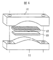
図4に示す治具(SUS316L製)を用いて応力腐食割れ試験を行った。3種の弁座材について、高温水中での応力腐食割れ試験を実施した。3種の弁座材として、40mm×10mm×0.6mmtの板状試験片10を切り出して、試験片10の表面にグラファイトウール12による人工隙間と曲げ半径100mmによる約0.3%の曲げひずみを付与して、温度288℃、圧力85気圧、溶存酸素約8ppmの高温水中に500時間浸漬した。試験後に試験片長手中央方向で切断し、割れが開口する程度の曲げを加えてから断面の光学顕微鏡観察を行った。
A stress corrosion cracking test was conducted using a jig (manufactured by SUS316L) shown in FIG. Three types of valve seat materials were subjected to a stress corrosion cracking test in high-temperature water. A
その結果、本発明材では割れの発生が認められなかったのに対し、従来の肉盛材では最大で580μm、又比較材では最大で540μm程度の割れが発生し、粉末冶金法で作製した微細なクロム炭化物を有する本発明材は耐応力腐食割れ性にも優れていることが確認された。 As a result, cracks were not observed in the present invention material, whereas cracks of up to 580 μm occurred in the conventional cladding material and 540 μm maximum in the comparative material, and the fine material produced by the powder metallurgy method It was confirmed that the material of the present invention having an excellent chromium carbide is excellent in resistance to stress corrosion cracking.
又、高温水中での長時間浸漬試験あるいはストラウス試験(JIS G0575)において、本発明材の耐食性が優れていることが確認された。 Further, in the long-time immersion test or Strauss test (JIS G0575) in high-temperature water, it was confirmed that the corrosion resistance of the material of the present invention was excellent.
更に、本実施例では、前述の本発明で作製した仕切り弁から液相拡散接合部を切り出して、弁座材コバルト基合金と弁基材SCPH2との間の接合せん断強度を評価した。その結果、せん断試験による試験片の破断はSCPH2内部で生じており、液相拡散接合部のせん断強度はSCPH2のせん断強度よりも高いことが確認された。 Furthermore, in this example, a liquid phase diffusion bonded portion was cut out from the above-described gate valve produced in the present invention, and the joint shear strength between the valve seat cobalt base alloy and the valve base material SCPH2 was evaluated. As a result, it was confirmed that the fracture of the test piece by the shear test occurred inside the SCPH2, and the shear strength of the liquid phase diffusion joint was higher than that of the SCPH2.
なお、接合部の金属ミクロ組織観察及び成分分析を行った結果、インサート材側に弁座、弁体及び弁箱の材料に含まれる合金元素が拡散しているのが確認された。特に、耐食性向上に有効なクロムが弁座側からインサート材側に拡散侵入しており、接合部の耐食性が確保された。 As a result of metal microstructure observation and component analysis of the joint, it was confirmed that the alloy elements contained in the valve seat, valve body and valve box materials were diffused on the insert material side. In particular, chromium effective for improving corrosion resistance diffused and penetrated from the valve seat side to the insert material side, and the corrosion resistance of the joint portion was ensured.
以上のように、本実施例によれば、クロム炭化物が平均粒径5μm以下の粒状又は塊状に均一に分断されているので、弁の弁座の耐衝撃性・耐食性・耐エロージョン性に優れた各種弁類を提供できる。 As described above, according to this example, the chromium carbide is uniformly divided into particles or lumps having an average particle size of 5 μm or less, so that the valve valve seat has excellent impact resistance, corrosion resistance, and erosion resistance. Various valves can be provided.
更に、平均粒径が5μm以下の粒状又は塊状のクロム炭化物を有するコバルト基合金によって弁座の表面が形成されることにより、循環水系統に過酸化水素水等の薬剤が注入され溶存酸素量が増加しても、腐食損傷が生じにくくなる。また、弁体と弁箱との摺動部の耐エロージョン性や摩擦抵抗増加が抑制され、弁座面の荒れによる耐漏洩性能低下も抑制され、これらの効果により保守性も向上される。 Furthermore, the surface of the valve seat is formed by a cobalt-based alloy having a granular or massive chromium carbide having an average particle size of 5 μm or less, so that a chemical such as hydrogen peroxide is injected into the circulating water system and the dissolved oxygen amount is reduced. Even if it increases, corrosion damage is less likely to occur. Further, the erosion resistance and the frictional resistance increase of the sliding portion between the valve body and the valve box are suppressed, the deterioration of the leakage resistance performance due to the rough valve seat surface is also suppressed, and the maintainability is improved by these effects.
本実施例の弁類は、タービン、ポンプ、送風機等の流体機械、内燃機関、化学プラント、火力プラント又は原子力プラントに使用することができる。本実施例が適用される弁の種類は、特に限定されるものではないが、逆止弁、安全弁等のような衝撃摩耗を伴う弁に好適である。 The valves of the present embodiment can be used for fluid machines such as turbines, pumps, and blowers, internal combustion engines, chemical plants, thermal power plants, or nuclear power plants. The type of the valve to which the present embodiment is applied is not particularly limited, but is suitable for a valve with impact wear such as a check valve and a safety valve.
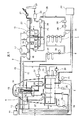
図5は、原子炉の一次冷却材が循環する配管系統を有するABWR原子力発電プラントの概略図である。一次冷却材が循環する配管系統には、図示を省略したが多くの弁が使用されており、これらの弁に実施例1に記載の本発明の弁が適用される。図5の原子力発電プラントにおいて、一次冷却材は、原子炉圧力容器14で熱せられ、高温高圧蒸気となって主蒸気管15を通って、高圧夕一ビン18へ導入される。次いで、高圧タービン18からの排出した蒸気は低圧夕一ビン19に導入され、発電機20を駆動する。高圧タービン18及び低圧夕一ビン19からの排出蒸気は、主蒸気復水器26を経た後、本発明の弁を多数有する給水系6により給水ポンプ30、高圧給水加熱器31を経て給水管9を通って原子炉圧力容器14に復水する。図3には他、冷却材浄化系熱交換器5、給水加熱器7、再循環系配管8、主復水器10、ほう酸スプレ系のSLCタンク11、SLCポンプ12、燃料格納容器13、給水管16、湿分分析器17、主変圧器21、排気筒22、オフガス処理系23、空気抽出器24、低圧復水ポンプ25、復水貯蔵槽27、復水ろ過装置28、復水脱塩装置29、制御棒駆動系32、熱交換器33、38、ろ過脱塩器34、原子炉隔離時冷却系35、高圧復水ポンプ36を示している。
FIG. 5 is a schematic diagram of an ABWR nuclear power plant having a piping system through which primary reactor coolant circulates. Although not shown, many valves are used in the piping system through which the primary coolant circulates, and the valve of the present invention described in the first embodiment is applied to these valves. In the nuclear power plant of FIG. 5, the primary coolant is heated in the
以上、本実施例によれば、クロム炭化物が平均粒径5μm以下の粒状又は塊状に均一に分断されているので、弁の弁座として高硬度で高靱性、耐衝撃性、耐食性、耐エロージョン性に優れた各種弁類を提供でき、特に、原子力発電プラント内に配備される弁を、本実施例の弁で構成することにより、弁の寿命を延ばすことができる。 As described above, according to the present embodiment, the chromium carbide is uniformly divided into a granular shape or a lump shape having an average particle size of 5 μm or less, so that it has high hardness and high toughness, impact resistance, corrosion resistance, and erosion resistance as a valve seat. It is possible to provide a variety of valves excellent in the above, and in particular, by configuring the valve provided in the nuclear power plant with the valve of this embodiment, the life of the valve can be extended.
又、クロム炭化物を有する共晶炭化物が平均粒径が5μm以下の粒状又は塊状に微細に分断されているので、循環水系統に過酸化水素水等の薬剤が注入され溶存酸素量が増加しても、流体中の溶存酸素による共晶炭化物の腐食損傷が生じにくくなり、このため、弁体と弁箱との摺動部の弁座面での耐エロージョン性や摩擦抵抗増加が抑制され、弁座面の荒れによる耐漏洩性能低下も抑制される。これらの効果により保守性も向上される。 Moreover, since the eutectic carbide having chromium carbide is finely divided into particles or lumps having an average particle diameter of 5 μm or less, chemicals such as hydrogen peroxide are injected into the circulating water system, increasing the amount of dissolved oxygen. However, corrosion damage of eutectic carbide due to dissolved oxygen in the fluid is less likely to occur, so that the erosion resistance and frictional resistance increase at the valve seat surface of the sliding part between the valve body and the valve box are suppressed, and the valve Leakage-resistant performance deterioration due to rough seating is also suppressed. These effects also improve maintainability.
1a…弁体側の弁座、1b…弁箱側の弁座、3…弁箱、4a、4b…弁座シート、5…弁体、10…試験片、10a、10b…コバルト基合金リング、11…試験治具、12…グラファイトウール。
DESCRIPTION OF
Claims (17)
Priority Applications (1)
| Application Number | Priority Date | Filing Date | Title |
|---|---|---|---|
| JP2004111669A JP4063236B2 (en) | 2004-04-06 | 2004-04-06 | Valve, manufacturing method thereof, power plant using the same, and valve member |
Applications Claiming Priority (1)
| Application Number | Priority Date | Filing Date | Title |
|---|---|---|---|
| JP2004111669A JP4063236B2 (en) | 2004-04-06 | 2004-04-06 | Valve, manufacturing method thereof, power plant using the same, and valve member |
Publications (2)
| Publication Number | Publication Date |
|---|---|
| JP2005290529A true JP2005290529A (en) | 2005-10-20 |
| JP4063236B2 JP4063236B2 (en) | 2008-03-19 |
Family
ID=35323791
Family Applications (1)
| Application Number | Title | Priority Date | Filing Date |
|---|---|---|---|
| JP2004111669A Expired - Lifetime JP4063236B2 (en) | 2004-04-06 | 2004-04-06 | Valve, manufacturing method thereof, power plant using the same, and valve member |
Country Status (1)
| Country | Link |
|---|---|
| JP (1) | JP4063236B2 (en) |
Cited By (11)
| Publication number | Priority date | Publication date | Assignee | Title |
|---|---|---|---|---|
| JP2010504425A (en) * | 2006-09-22 | 2010-02-12 | ホガナス アクチボラグ (パブル) | Metallurgical powder composition and production method |
| JP2010117051A (en) * | 2008-11-11 | 2010-05-27 | Nippon Steel Corp | Highly resistant burner tip |
| CN102808689A (en) * | 2011-06-01 | 2012-12-05 | 霍尼韦尔国际公司 | Valve seat and gasket for exhaust bypass valve |
| JP2013194902A (en) * | 2012-03-22 | 2013-09-30 | Toshiba Corp | Valve, and power generation plant using the same |
| JP5323927B2 (en) * | 2009-03-27 | 2013-10-23 | 国立大学法人 東京大学 | Joining method |
| US9163589B2 (en) | 2013-05-30 | 2015-10-20 | Honeywell International Inc. | Valve seat and gasket for exhaust gas bypass for turbocharger |
| JP2018100650A (en) * | 2016-12-22 | 2018-06-28 | 日立オートモティブシステムズ株式会社 | Fuel flow passage, high-pressure pump for vehicle fuel and vehicle |
| JP2019117077A (en) * | 2017-12-26 | 2019-07-18 | 日立Geニュークリア・エナジー株式会社 | Corrosion-resistant and wear-resistant built-up, method for forming corrosion-resistant and wear-resistant built-up and corrosion-resistant and wear-resistant valve |
| JP2019152859A (en) * | 2018-03-01 | 2019-09-12 | キヤノン株式会社 | Manufacturing method of optical component, optical component, interchangeable lens, optical instrument, quick return mirror and camera |
| JP2020112424A (en) * | 2019-01-11 | 2020-07-27 | 日立Geニュークリア・エナジー株式会社 | Build-up metal part inspection method and valve manufacturing method using the same |
| WO2023082335A1 (en) * | 2021-11-14 | 2023-05-19 | 重庆三爱海陵实业有限责任公司 | Valve and high-temperature-resistant alloy thereof |
Families Citing this family (1)
| Publication number | Priority date | Publication date | Assignee | Title |
|---|---|---|---|---|
| CN107725806A (en) * | 2017-10-13 | 2018-02-23 | 南通国电电站阀门股份有限公司 | Supercritical high pressure band bypasses expanding without pod apertures parallel gate valve |
-
2004
- 2004-04-06 JP JP2004111669A patent/JP4063236B2/en not_active Expired - Lifetime
Cited By (16)
| Publication number | Priority date | Publication date | Assignee | Title |
|---|---|---|---|---|
| JP2010504425A (en) * | 2006-09-22 | 2010-02-12 | ホガナス アクチボラグ (パブル) | Metallurgical powder composition and production method |
| KR101499707B1 (en) * | 2006-09-22 | 2015-03-06 | 회가내스 아베 (피유비엘) | Metallurgy powder composition, and manufacturing method |
| JP2010117051A (en) * | 2008-11-11 | 2010-05-27 | Nippon Steel Corp | Highly resistant burner tip |
| JP5323927B2 (en) * | 2009-03-27 | 2013-10-23 | 国立大学法人 東京大学 | Joining method |
| CN102808689A (en) * | 2011-06-01 | 2012-12-05 | 霍尼韦尔国际公司 | Valve seat and gasket for exhaust bypass valve |
| US20120304952A1 (en) * | 2011-06-01 | 2012-12-06 | Honeywell International Inc. | Valve seat and gasket for exhaust bypass valve |
| US8667794B2 (en) * | 2011-06-01 | 2014-03-11 | Honeywell International Inc. | Valve seat and gasket for exhaust bypass valve |
| JP2013194902A (en) * | 2012-03-22 | 2013-09-30 | Toshiba Corp | Valve, and power generation plant using the same |
| US9163589B2 (en) | 2013-05-30 | 2015-10-20 | Honeywell International Inc. | Valve seat and gasket for exhaust gas bypass for turbocharger |
| JP2018100650A (en) * | 2016-12-22 | 2018-06-28 | 日立オートモティブシステムズ株式会社 | Fuel flow passage, high-pressure pump for vehicle fuel and vehicle |
| JP2019117077A (en) * | 2017-12-26 | 2019-07-18 | 日立Geニュークリア・エナジー株式会社 | Corrosion-resistant and wear-resistant built-up, method for forming corrosion-resistant and wear-resistant built-up and corrosion-resistant and wear-resistant valve |
| JP2019152859A (en) * | 2018-03-01 | 2019-09-12 | キヤノン株式会社 | Manufacturing method of optical component, optical component, interchangeable lens, optical instrument, quick return mirror and camera |
| JP7532011B2 (en) | 2018-03-01 | 2024-08-13 | キヤノン株式会社 | Manufacturing method of optical components, optical equipment |
| JP2020112424A (en) * | 2019-01-11 | 2020-07-27 | 日立Geニュークリア・エナジー株式会社 | Build-up metal part inspection method and valve manufacturing method using the same |
| JP7028808B2 (en) | 2019-01-11 | 2022-03-02 | 日立Geニュークリア・エナジー株式会社 | A method for inspecting the metal part and a method for manufacturing a valve using the method. |
| WO2023082335A1 (en) * | 2021-11-14 | 2023-05-19 | 重庆三爱海陵实业有限责任公司 | Valve and high-temperature-resistant alloy thereof |
Also Published As
| Publication number | Publication date |
|---|---|
| JP4063236B2 (en) | 2008-03-19 |
Similar Documents
| Publication | Publication Date | Title |
|---|---|---|
| CN1307380C (en) | Valve and its mfg. method | |
| JP4063236B2 (en) | Valve, manufacturing method thereof, power plant using the same, and valve member | |
| US6889957B2 (en) | Joint construction of cobalt-based alloy | |
| DE60127503T2 (en) | Nuclear power plant with valves made of corrosion-resistant and wear-resistant alloy | |
| JP2009161802A (en) | Highly corrosion-resistant austenitic stainless steel, nuclear power generation plant constructed by using the stainless steel, weld joint and structural member | |
| EP2494158B1 (en) | An exhaust valve spindle for an internal combustion engine, and a method of manufacturing | |
| US11174536B2 (en) | Transition metal-based materials for use in high temperature and corrosive environments | |
| US6672330B2 (en) | Valve bonded with corrosion and wear proof alloy and apparatuses using said valve | |
| JP3598977B2 (en) | Valves joined with corrosion and wear resistant alloys | |
| CN107988566A (en) | Steel for 600 MPa-grade nuclear first-grade equipment and manufacturing method thereof | |
| JP3503565B2 (en) | Valve and nuclear power plant using the same | |
| JP2005194602A (en) | Valve, mechanical seal and manufacturing method thereof | |
| JP3721300B2 (en) | valve | |
| Wu et al. | Microstructures and mechanical properties of a 30CrNi2MoV steel/GH4098 joint produced by hot-compression bonding | |
| HK1051664A (en) | Joint construction of cobalt-based alloy | |
| JPH1072642A (en) | Wear-resistant alloy and control rod drive and nuclear reactor using the same | |
| JP3131175B2 (en) | Alloy for sliding material and equipment using the alloy | |
| JP2003028315A (en) | Method of manufacturing valve device for nuclear / thermal power plant | |
| Goodall | Development of a Novel Ni-Based Multi-principal Element Alloy Filler Metal, Using an Alternative Melting Point Depressant | |
| Li et al. | Microstructure and Mechanical Properties of High Power CO 2 Laser Welded Inconel 625 Nickel Based Alloy. | |
| CN117600591A (en) | A new brazing process for connecting TZM and high-strength graphite with TiZrNbTa solder | |
| Horowitz | ICONE19-43335 FURTHER BASIC STUDIES NEEDED TO SPECIFY MATERIALS FOR SODIUM COOLED FAST REACTORS | |
| JPH09209066A (en) | Alloy material for sliding member, and equipment for high temperature and high pressure use | |
| Liu et al. | Laser Cladding of Ni-Based Hardfacing Alloy Replacing Stellite06 | |
| Callegaro et al. | Mechanical alloying of high performance aluminum alloys |
Legal Events
| Date | Code | Title | Description |
|---|---|---|---|
| A621 | Written request for application examination |
Free format text: JAPANESE INTERMEDIATE CODE: A621 Effective date: 20060525 |
|
| A977 | Report on retrieval |
Free format text: JAPANESE INTERMEDIATE CODE: A971007 Effective date: 20070404 |
|
| A131 | Notification of reasons for refusal |
Free format text: JAPANESE INTERMEDIATE CODE: A131 Effective date: 20070724 |
|
| A521 | Request for written amendment filed |
Free format text: JAPANESE INTERMEDIATE CODE: A523 Effective date: 20070913 |
|
| TRDD | Decision of grant or rejection written | ||
| A01 | Written decision to grant a patent or to grant a registration (utility model) |
Free format text: JAPANESE INTERMEDIATE CODE: A01 Effective date: 20071211 |
|
| A61 | First payment of annual fees (during grant procedure) |
Free format text: JAPANESE INTERMEDIATE CODE: A61 Effective date: 20071224 |
|
| R150 | Certificate of patent or registration of utility model |
Free format text: JAPANESE INTERMEDIATE CODE: R150 Ref document number: 4063236 Country of ref document: JP Free format text: JAPANESE INTERMEDIATE CODE: R150 |
|
| FPAY | Renewal fee payment (event date is renewal date of database) |
Free format text: PAYMENT UNTIL: 20110111 Year of fee payment: 3 |
|
| FPAY | Renewal fee payment (event date is renewal date of database) |
Free format text: PAYMENT UNTIL: 20110111 Year of fee payment: 3 |
|
| FPAY | Renewal fee payment (event date is renewal date of database) |
Free format text: PAYMENT UNTIL: 20120111 Year of fee payment: 4 |
|
| FPAY | Renewal fee payment (event date is renewal date of database) |
Free format text: PAYMENT UNTIL: 20130111 Year of fee payment: 5 |
|
| EXPY | Cancellation because of completion of term |