JP7532011B2 - Manufacturing method of optical components, optical equipment - Google Patents
Manufacturing method of optical components, optical equipment Download PDFInfo
- Publication number
- JP7532011B2 JP7532011B2 JP2019033395A JP2019033395A JP7532011B2 JP 7532011 B2 JP7532011 B2 JP 7532011B2 JP 2019033395 A JP2019033395 A JP 2019033395A JP 2019033395 A JP2019033395 A JP 2019033395A JP 7532011 B2 JP7532011 B2 JP 7532011B2
- Authority
- JP
- Japan
- Prior art keywords
- metallic material
- optical
- lens
- barrel
- skeletal structure
- Prior art date
- Legal status (The legal status is an assumption and is not a legal conclusion. Google has not performed a legal analysis and makes no representation as to the accuracy of the status listed.)
- Active
Links
Images


Landscapes
- Lens Barrels (AREA)
- Cameras In General (AREA)
Description
本発明は、他の部材と当接する摺動部を備えた光学部品の製造方法、光学機器に関する。 The present invention relates to a method for manufacturing an optical component having a sliding portion that comes into contact with another member, and to an optical device.
従来、カメラなどの光学機器に用いられる光学製品(光学部品)、例えば特に焦点距離が長く大型の望遠レンズなどの光学製品では、その可搬性や撮影時の機動性から、レンズ鏡筒部の軽量化、あるいは小型化の要求が強くなっている。そのためレンズを保持する鏡筒部を構成する部品の樹脂化や薄肉化などが進められている。 Conventionally, for optical products (optical components) used in optical devices such as cameras, particularly large telephoto lenses with long focal lengths, there has been a strong demand for lighter and more compact lens barrels for portability and maneuverability during shooting. As a result, there has been a trend toward using resin and thinning the parts that make up the barrel that holds the lens.
従来、各種工業製品を構成する部品の小型化軽量化のために、それまで金属製であった部品全体ないしその一部をより比重の軽い樹脂に変更する手法が知られている。また、その場合、同時に、金属部や樹脂部の寸法、特に厚みを薄肉化する配慮が取られることがある。例えば、下記の特許文献1には、鏡筒の剛性や強度と軽量化を考慮し、金属部材と樹脂部材を一体成形加工により一体化する構造が開示されている。また、光学鏡筒などにおいては、下記の特許文献2のように、軽量かつ変形しづらい網目構造の突出部分を持つ筒部品が提案されている。
Conventionally, in order to reduce the size and weight of parts that make up various industrial products, a method has been known in which all or part of a part that was previously made of metal is changed to resin, which has a lighter specific gravity. In such cases, consideration may also be given to reducing the dimensions, particularly the thickness, of the metal and resin parts at the same time. For example,
例えば焦点距離が500mm~1000mmを超えるような長焦点距離かつ大口径のレンズを搭載する望遠レンズでは、総重量がKgオーダに及ぶ構成となることがある。このような光学製品は、例えばミラー式ないしミラーレスの一眼レフカメラの交換レンズなどとして存在する。このような光学製品は、携行性、取り扱いを容易にするため、できるだけ軽量に構成できれば好適である。しかしながら、この種の交換レンズのような光学製品では、光学素子や機構部品それ自体が大型であり自重が大きいため、強度や摺動部の耐摩耗性の観点から、鏡筒部の筺体部品を単純に金属から樹脂に置き換えることが困難である場合がある。 For example, a telephoto lens equipped with a lens with a long focal length and large aperture, such as one with a focal length of over 500 mm to 1000 mm, can have a total weight on the order of kilograms. Such optical products exist, for example, as interchangeable lenses for mirror-type or mirrorless single-lens reflex cameras. It is ideal for such optical products to be as lightweight as possible to facilitate portability and handling. However, in optical products such as this type of interchangeable lens, the optical elements and mechanical parts themselves are large and heavy, so from the standpoint of strength and wear resistance of sliding parts, it may be difficult to simply replace the housing parts of the lens barrel from metal to resin.
また、一般に、レンズ鏡筒では、迷光によるゴーストやフレアが発生する部位に筺体部品の内面には遮光線と呼ばれるV字状の溝を形成する構造が必要になることがある。このような溝加工を行う場合には、樹脂部分の薄肉化が難しくなる場合がある。また、レンズ鏡筒のような光学製品では、外乱光がレンズ内に照射されるのを防止するため、その筺体と、内部の光軸付近の空間との間には厳重な遮光性が必要である。従って、レンズ鏡筒の筺体部品の要部は必要な遮光性を有している必要がある。例えば、レンズ鏡筒を構成する案内筒やカム筒などの光学部品には、軽量化を目的として、内外を貫通する開口部を含む構造を採用することが事実上、不可能なものがある。 In addition, generally, in a lens barrel, a structure may be required to form a V-shaped groove called a light shielding line on the inner surface of the housing part in a portion where ghosts or flares due to stray light occur. When performing such groove processing, it may be difficult to make the resin part thin. In addition, in an optical product such as a lens barrel, strict light shielding is required between the housing and the space around the internal optical axis to prevent disturbance light from being irradiated into the lens. Therefore, the main parts of the housing parts of the lens barrel must have the necessary light shielding properties. For example, for optical parts such as the guide tube and cam tube that make up the lens barrel, it is practically impossible to adopt a structure that includes an opening that penetrates from the inside to the outside in order to reduce weight.
本発明の課題は、上記の問題点に鑑み、必要な強度や耐摩耗性を備えた小型軽量な光学部品ないし同光学部品を備えた光学機器を提供することにある。 In view of the above problems, the object of the present invention is to provide a small, lightweight optical component with the necessary strength and wear resistance, or an optical device equipped with such an optical component.
本発明の第1の態様は、第1の金属材料から成る部分を有する基材部に対して、前記第1の金属材料とは主体が異なる第2の金属材料によって肉盛り造形を行う工程と、前記基材部のうちの前記第1の金属材料から成る第1部位と、前記基材部のうちの前記第2の金属材料で覆われた第2部位の前記第1の金属材料から成る第1部分と、前記第2の金属材料のうちの前記第1部分を覆う第2部分と、を残しつつ、前記第2部位の第3部分と、前記第2の金属材料のうちの前記第3部分を覆う第4部分と、前記基材部のうちの第3部位と、を除去するように前記基材部に貫通口を形成する工程と、を含み、前記第1部位および前記第3部位は、前記第3部分と前記第4部分とが並ぶ方向において前記第2の金属材料で覆われておらず、前記第1部位は前記第1部分に連続しており、前記第2部分は前記第4部分に連続している光学部品の製造方法である。 A first aspect of the present invention is a method for manufacturing an optical component, comprising: a step of performing build-up molding on a base portion having a portion made of a first metallic material using a second metallic material having a different main component from the first metallic material; and a step of forming a through hole in the base portion so as to remove a third portion of the second portion, a fourth portion of the second metallic material covering the third portion of the second metallic material, and the third portion of the base portion, while leaving a first portion of the base portion made of the first metallic material, a first portion of the second portion of the base portion covered with the second metallic material, and a second portion of the second metallic material covering the first portion, wherein the first portion and the third portion are not covered with the second metallic material in the direction in which the third portion and the fourth portion are arranged, the first portion is continuous with the first portion, and the second portion is continuous with the fourth portion.
上記の構成により、本発明によれば、必要な強度や耐摩耗性を有し、小型軽量な光学部品ないし同光学部品を備えた光学製品を提供することができる。 With the above configuration, the present invention can provide a small, lightweight optical component or an optical product equipped with the optical component that has the necessary strength and wear resistance.
以下、添付図面を参照して本発明を実施するための形態につき説明する。なお、以下に示す構成はあくまでも一例であり、例えば細部の構成については本発明の趣旨を逸脱しない範囲において当業者が適宜変更することができる。また、本実施形態で取り上げる数値は、参考数値であって、本発明を限定するものではない。 Below, a description will be given of an embodiment of the present invention with reference to the attached drawings. Note that the configuration shown below is merely an example, and those skilled in the art can appropriately change the detailed configuration, for example, without departing from the spirit of the present invention. Also, the numerical values used in this embodiment are for reference only and do not limit the present invention.
<実施形態1>
本実施形態では、低比重な第1の金属材料から成る内面遮光部と、この内面遮光部に対して結合され、所定の強度と耐摩耗性を有する異なる第2の金属材料からなる骨格構造部および摺動部を備えた光学部品とその製造方法を例示する。以下の実施形態では、この光学部品の一例として鏡筒部品を示す。
<
In this embodiment, an optical component including an inner surface light-shielding portion made of a first metal material having a low specific gravity, and a skeletal structure and a sliding portion made of a different second metal material having a predetermined strength and abrasion resistance that is bonded to the inner surface light-shielding portion, and a method for manufacturing the optical component will be described. In the following embodiment, a lens barrel component will be shown as an example of the optical component.
本実施形態では、光学部品の内面遮光部は、押出し成形や鋳造(たとえばダイキャスト)の工程で、あるいはさらに鋳造後の切削、プレス加工などにより形成する。内面遮光部の形成される部位は、光学部品の剛性ないし強度を保つ機能の一部を構成するとともに、遮光性や反射防止特性などの光学特性を付与するための部位として機能する。このうち、遮光性は不透明材料である金属を用いることにより付与される。反射防止特性は、後加工により遮光線(遮光溝)を形成することや、静電植毛や艶消し塗装などの反射防止表面処理を必要な部位に形成することにより付与される。 In this embodiment, the inner light-shielding portion of the optical component is formed during the process of extrusion molding or casting (e.g., die casting), or by further cutting or pressing after casting. The portion where the inner light-shielding portion is formed constitutes part of the function of maintaining the rigidity or strength of the optical component, and also functions as a portion for imparting optical properties such as light-shielding and anti-reflection properties. Of these, light-shielding properties are imparted by using a metal, which is an opaque material. Anti-reflection properties are imparted by forming light-shielding lines (light-shielding grooves) through post-processing, or by forming anti-reflection surface treatments such as electrostatic flocking or matte coating in the required areas.
一方、光学部品の骨格構造部および摺動部は内面遮光部上に粉末供給法による異なる金属材料の3Dプリントにより形成し、3Dプリント後の切削によって精度や表面性を付与する。骨格構造部は、主に当該の光学部品の剛性ないし強度を維持し、摺動部は主に当該の光学部品の耐摩耗性を維持する。なお、骨格構造部には上記3Dプリントによって網目状に骨格を形成する。これにより骨格構造部の体積を削減し、当該の光学部品の軽量化を図ることができる。なお、以下実施形態では、内面遮光部と骨格構造部を基材部と称する場合がある。 On the other hand, the skeletal structure and sliding parts of the optical component are formed on the inner light-shielding part by 3D printing different metal materials using a powder supply method, and precision and surface properties are imparted by cutting after 3D printing. The skeletal structure mainly maintains the rigidity and strength of the optical component, and the sliding parts mainly maintain the wear resistance of the optical component. Note that a mesh-like skeleton is formed in the skeletal structure by the above-mentioned 3D printing. This reduces the volume of the skeletal structure, making it possible to reduce the weight of the optical component. Note that in the following embodiments, the inner light-shielding part and the skeletal structure may be referred to as the base material part.
本実施形態1では、上記の光学部品として、鏡筒部品(鏡筒筐体部品)を示す。本実施形態の鏡筒部品の内面遮光部は、その後の3Dプリンタによる積層形成が可能な骨格構造部や摺動部に融点が近いもしくは高い金属により構成される。 In this embodiment, the optical component is a lens barrel component (lens barrel housing component). The inner light-shielding portion of the lens barrel component in this embodiment is made of a metal with a close or high melting point, with a skeletal structure and sliding parts that can be subsequently laminated using a 3D printer.
一方、強度を保ちつつ軽量化するためビス締結部を含む剛性が必要な領域を残した骨格構造部は、摺動部よりも低比重な第1の金属材料から作製する。そして耐摩耗性が必要となる他部品との摺動部や結合部は、骨格構造部よりも耐摩耗性の高い第2の金属材料から作製する。本実施形態の製造方法の第2の工程では、この骨格構造部と摺動部を粉末供給法による3Dプリントすることにより異種材料から形成する。 On the other hand, the skeletal structure, which leaves areas requiring rigidity including screw fastening parts to reduce weight while maintaining strength, is made from a first metal material with a lower specific gravity than the sliding parts. The sliding parts and joints with other parts, which require wear resistance, are made from a second metal material that is more wear resistant than the skeletal structure. In the second step of the manufacturing method of this embodiment, the skeletal structure and sliding parts are formed from different materials by 3D printing using a powder supply method.
具体的には、本実施形態の光学部品は光学鏡筒の鏡筒を構成する鏡筒部品である。本実施形態の鏡筒部品は、鏡筒内で光学素子、特に合焦レンズを可動支持するフォーカスユニットの内筒(案内筒)である。この内筒(案内筒)では、フォーカスユニットの直進カム部やカム筒と摺動する嵌合部付近のような摺動部を耐摩耗性の高い金属から構成する。これら摺動部には耐摩耗性を向上するため、表面処理を加えてもよい。 Specifically, the optical component of this embodiment is a lens barrel part that constitutes the lens barrel of an optical lens barrel. The lens barrel part of this embodiment is the inner tube (guide tube) of the focus unit that movably supports the optical element, particularly the focusing lens, within the lens barrel. In this inner tube (guide tube), sliding parts such as the linear cam part of the focus unit and the vicinity of the fitting part that slides with the cam tube are made of a metal with high wear resistance. These sliding parts may be surface-treated to improve wear resistance.
その他の部位は耐摩耗性の高い金属よりも比重の低い金属で形成し、強度を損なわない程度に肉抜きした骨格構造部とする。また、内筒(案内筒)は、外光が撮影(観察)光路に入射しないよう、円周面は遮光性を有する光学特性部となっている必要がある。また、内筒(案内筒)の内面部は、光学特性部では光が反射しゴーストやフレアが発生するのを防止するため、内面部には、遮光線(遮光溝)を形成する、あるいは静電植毛、艶消し塗装などの表面処理を施すなどとして、反射防止面とする。この反射防止面に関しては、遮光線よりも静電植毛、艶消し塗装などの表面処理の方が金属の厚みを薄くでき、鏡筒部品の厚みを薄くでき、より軽量化が図れる可能性がある。 The other parts are made of metal with a lower specific gravity than highly wear-resistant metals, and are hollowed out to the extent that strength is not lost as a skeletal structure. The inner tube (guide tube) must have a circumferential surface with light-shielding optical properties to prevent external light from entering the shooting (observation) optical path. The inner surface of the inner tube (guide tube) is made an anti-reflective surface by forming a light-shielding line (light-shielding groove) on the inner surface or by applying a surface treatment such as electrostatic flocking or matte painting to prevent light from reflecting in the optical properties and causing ghosts and flares. With regard to this anti-reflective surface, surface treatments such as electrostatic flocking or matte painting allow the metal to be thinner than light-shielding lines, which allows the thickness of the telescope tube parts to be thinner and may lead to further weight reduction.
図2は、本実施形態の鏡筒部品を用いることができる光学機器として、一眼レフデジタルカメラの構成を示している。図2において、撮影レンズ1にカメラ本体2が接続されている。被写体からの光は撮影レンズ1に含まれるレンズ3などの光学レンズを介して撮影される。撮影前は主ミラー7により反射され、プリズム11を透過後、ファインダーレンズ12を通して撮影者に撮影画像が映し出される。また、主ミラー7はハーフミラーとなっており、主ミラーを透過した光はサブミラー8によりAF(オートフォーカス)ユニット13の方向に反射され、例えばこの反射光は測距に使用される。
Figure 2 shows the configuration of a single-lens reflex digital camera as an optical device that can use the lens barrel component of this embodiment. In Figure 2, a
撮影時には、不図示の駆動機構を介して、主ミラー7とサブミラー8を光路外に移動させ、シャッター9を開き、撮像素子10に撮影レンズ1から入射した撮影光像を結像させる。また、絞り6は、開口面積を変更することにより撮影時の明るさや焦点深度を変更するために用いられる。なお、図2の一眼レフカメラの撮像素子10に替えて銀塩フィルムに変更する場合でも、本実施形態の鏡筒部品に関しては、後述同様の構成を実施することができる。また、撮影レンズ1は、カメラ本体2に固定的に装着されていてもよいが、この種の光学機器では、多くの場合、撮影レンズ1はカメラ本体2のボディに対して着脱可能な交換レンズとして構成される。
When taking a photograph, the
撮影レンズ1は、フォーカスユニット4の内部のフォーカスレンズ5の位置を光軸方向に可変移動させることで、合焦状態を調節することができるよう構成される。なお、本実施形態の鏡筒部品はこの焦点距離を調節するフォーカスユニット4を構成するものであるが、同様の鏡筒部品の構成を、倍率を可変調節するズームユニットなどに適用することもできる。本実施形態のフォーカスユニット4の構成例について図3(A)、(B)、および図4に示す。
The
図3(A)、(B)、図4に示すように、本実施形態のフォーカスユニット4は、外筒であるカム筒14と、本実施形態の鏡筒部品に相当する内筒としての案内筒15を備える。カム筒14、案内筒15は斜めカム(斜めカム)および直進カムをそれぞれ備え、フォーカスレンズ5をユニット内の光軸上で前進または後退させることができるよう構成される。カム筒14は、撮影者によって回転操作が可能な撮影レンズ1のフォーカスリング(不図示)などと結合される。これにより、撮影者は、例えばファインダーレンズ12(図2)を介して合焦状態を観察しながらフォーカスリングを操作してフォーカス調整を行うことができる。
As shown in Figures 3(A), (B) and 4, the
カム筒14には、例えばその円周上の120°間隔の配置で斜めカム17が形成され、一方、案内筒15には120°間隔配置で直進カム18が形成されている。フォーカスレンズ5は、フォーカスレンズホルダ16により内筒側の案内筒15に固定されている。フォーカスレンズホルダ16には例えば120°間隔でベアリング19が取り付けられている。
The
ベアリング19は斜めカム17と直進カム18に係合し位置が固定されている。カム筒14の内面は案内筒15の摺動部24、25(図8)と係合している。また、案内筒15にはベアリング22がビス締結穴23にビス締結されており、ベアリング22はカム筒14にも係合する。
The
図4に示すように、案内筒15に接触しているワッシャースプリング21により、チャージ筒20はカム筒14を光軸方向に付勢する。これにより、ベアリング22とチャージ筒20によりカム筒14は図3における斜め右下方向に付勢された状態で、フォーカスレンズ5の光軸方向の位置が維持されることになる。案内筒15はビス締結部28(図3(A))により、フォーカスユニット4の外側の鏡筒部品、例えば外装部(不図示)に締結される。
As shown in Figure 4, the
一方、カム筒14はキー溝26、27を介して、光軸を中心に回転駆動するフォーカスキー部品としてのフォーカスリング(不図示)に係合し、ユーザにより回転操作される。このカム筒14の回転動作により、直進カム18に係合しているベアリング19が斜めカム17に沿って光軸方向に移動し、フォーカスレンズ5が光軸方向に移動し、これによりピント調整が行われる。
The
本実施形態の案内筒15は、鏡筒部品の基材部となる中空の円筒状の母材に対して、耐摩耗性を有する直進カム18の摺動部、摺動部24、25を、異なる金属材料から、3Dプリントによって作製する。また、鏡筒部品ないし完成した鏡筒全体の強度を保つための骨格構造部も3Dプリントによって作製してもよいが、骨格構造部は、ダイキャストや母材に対する切削加工など、別の方法で作製してもよい。この3Dプリントの方式には、例えば粉末供給法を用いる。
In the present embodiment, the
ここで、本実施形態の鏡筒部品に相当する案内筒15について詳細に説明する。案内筒15の要部である基材部は、図5に示す中空円筒状の母材61から作製する。この母材61の一部は、本実施形態では、その完成後に、ほぼ全体には遮光性、および内面には反射防止特性のような光学特性を有する光学特性部の主要部を含むことになる。母材61は、鋳造、あるいは旋盤を用いた棒状の金属材料の中空切削などにより、形成される。あるいは、中空円筒状の母材61は、平板を両端部を溶接し筒状に形成するような手法によって形成してもよい。この母材61の加工は、案内筒15の所定の光学特性を有する光学特性部の主要形状部の形成工程(第1の工程)に相当する。
Here, the
続いて、母材61の外側の円周面に、図6に示ように、骨格構造部62(図1では65)と、同図中に斜線で示した摺動部63、64と、を3D造形により肉盛り造形することで作製する(第2の工程)。この3D造形には、粉末供給法による3Dプリンタを利用し、骨格構造部62(図1では65)と、摺動部63、64とでは異なる金属を材料粉末に用いる。また、摺動部63、64は、余肉を考慮した形状で3D造形する。例えば、摺動部63は、直進カム18の縁部を含む長穴形状に3D造形し、その後、下記のようにカム縁部を残して切削、除去される。また、摺動部64は、後の切削除去により最終的な寸法(高さ)となるよう、余裕を持った高さに3D造形される。
Next, as shown in FIG. 6, the skeletal structure 62 (65 in FIG. 1) and the sliding
その後、母材61の内周と、外周面側の骨格構造部62、ないし摺動部63、64の直進カム18の長穴の貫通口の部分を例えば切削により除去する(第3の工程)二次加工を行うことにより、完成した案内筒15は図1の状態になる。
Then, secondary processing is performed to remove the inner circumference of the
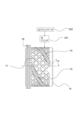
図1に示すように、案内筒15の骨格構造部65は、案内筒15の強度特性(例えば剛性)を維持するための格子による骨格構造を円筒外周面に備える。このような格子状構造によって、案内筒15に、径方向、ないし軸芯(通常フォーカスレンズ5の光軸と同軸)と平行な方向に沿った圧縮や、直進カム18のカム溝を介して加わる捩れ方向の外力に関する剛性を付与することができる。
As shown in FIG. 1, the
この格子構造は、例えば、規則的に画成、配置された複数の三角形、または四辺形形状の凹部66により構成される。この凹部66は、肉抜きによって全体の重量を低減する軽量化部を構成する。即ち、規則的に配置された凹部66によって、骨格構造部65の円筒構造のほぼ全体が肉抜きされ、骨格構造部65は著しく軽量化される。
This lattice structure is composed of, for example, a number of regularly defined and arranged triangular or quadrilateral recesses 66. These
さらに、骨格構造部65は、ベアリング22がビス締結されるビス締結穴23と座面35、36、ユニット外の鏡筒部品とのビス締結部28の座面と逃げ、ワッシャースプリング21との当接面32、チャージ筒20との係合する当接面33などを備える。
Furthermore, the
図1に示す程度の複雑さを有する形状であれば、骨格構造部65と、直進カム18の摺動部、摺動部24、25は、粉末供給法の3Dプリンタ301を用いて、それぞれ異なる金属材料から好適に作製することができる。一般に、粉末供給法での3Dプリンタによる部品作製では、切削加工に比べ精度が劣ることから、切削加工による二次加工後に所望の特性を有する材料で構成されるよう余肉などを考慮し3Dプリントデータ302を作成することが望ましい。
If the shape is as complex as that shown in FIG. 1, the
図7において、3Dプリンタ301によって、骨格構造部65と直進カム18の摺動部、摺動部24、25を造形する場合、例えば、円筒状の母材61の外周面から造形を開始する。その場合、例えば、母材61の軸芯を中心に母材61を回転させながら材料を切り替えつつ、肉盛り造形を繰り返す。
In FIG. 7, when the
この3D造形時には、3Dプリンタ301には、骨格構造部65と直進カム18、摺動部24、25を造形するための3Dプリントデータ302を供給しておく。この3Dプリントデータ302は、例えば上述の余肉を考慮した骨格構造部65と摺動部63、64の3DCADデータなどである。その場合、3Dプリンタ301が、3DCADデータを元に材料毎に肉盛り造形を行うための層(スライス)データに分解して用いる。このような層(スライス)データは、3Dプリントデータ302として3Dプリンタ301に供給してもよい。なお、サーバやホスト装置(不図示)から3Dプリンタ301に3Dプリントデータ302を供給する場合、3Dプリントデータ302はネットワーク通信によって送信してもよい。あるいは、各種の光ディスクやフラッシュメモリデバイスのようなコンピュータ読み取り可能な記録媒体に3Dプリントデータ302を格納して3Dプリンタ301に供給することもできる。その場合、これらのコンピュータ読み取り可能な記録媒体は、本発明の記録媒体を構成する。
During this 3D modeling, the
図7の例では、骨格構造部62の軸芯(通常フォーカスレンズ5の光軸と同軸)と平行な方向と、上記の傾斜した格子がなす角度は格子の傾斜角度(α)はほぼ45°に取られている。これにより、案内筒15は、上記の各方向のどの外力に対しても良好な強度特性(剛性)を維持することができる。
In the example of FIG. 7, the angle (α) between the direction parallel to the axis of the skeletal structure 62 (usually coaxial with the optical axis of the focus lens 5) and the inclined lattice is approximately 45°. This allows the
以上のように、円筒状の母材61上に、後の切削(第3の工程)を行うのに充分な余肉を考慮した厚みで骨格構造部62と摺動部63、64を異なる金属を粉末供給法により肉盛り3D造形する。その後、例えば母材61の内周と、外周面側の骨格構造部62、ないし摺動部63、64の直進カム18の長穴の貫通口の部分を、例えば切削によって除去する二次加工(第3の工程)を施す。
As described above, the
図8(A)は、3D造形により骨格構造部62と摺動部63、64を肉盛り造形した直後の母材61の断面を示している。また、図8(B)は、切削により二次加工を施した直後の図1の案内筒15の断面を示している。
Figure 8 (A) shows a cross section of the
図8(B)において、案内筒15の内面遮光部29、30は、円筒状の母材61から形成されているため、案内筒15の主要部である光学特性部に確実な遮光特性を付与することができる。また、内面遮光部29は、静電植毛や艶消し塗装などの反射防止表面処理が施すことができる。この内面遮光部29により、鏡筒内部で不要な光が反射しゴーストやフレアが発生することを防止することができる。また、この例では内面遮光部30は、切削加工などにより形成した遮光線により構成されている。しかしながら、内面遮光部30には、遮光線の構造を用いると、案内筒15の肉厚を大きく取る必要があり、薄型、軽量化を図るには静電植毛や艶消し塗装による反射防止表面処理の方がより好ましい可能性がある。
In FIG. 8B, the inner
案内筒15に3D造形した直進カム18の摺動部63、摺動部24、25、64および骨格構造部65の最終形状は、切削による二次加工により形成される。摺動部63、64(図8(A))の部位に対しては長穴の貫通口の部分の切削を行い、直進カム18(図1、図3)が形成される。3D造形した摺動部63、64の金属材料は、直進カム18の長穴縁部の構造として残る。
The final shapes of the sliding
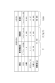
本実施形態1の案内筒15では、内面遮光部29、30および骨格構造部65は、図14に示すように、例えば比重が1.8のマグネシウム合金で、一方、直進カム18の摺動部、摺動部24、25は、比重が2.68のアルミニウム合金で形成する。この場合、同図のように本実施形態1の内面遮光部29、30の体積は4.95cm^3(^はべき乗を示す)、その重量は8.91gであり、骨格構造部65の体積は10.23cm^3、重量が18.41gとなっている。また、直進カム18の摺動部、摺動部24、25の体積は0.35cm^3、最終重量が0.94gとなっており、この例では、案内筒15の総重量は28.26gである。
In the
一方、比較例(1)(1203)は、本実施形態の凹部66を肉埋めした格子構造のない一般的な案内筒の形状を、耐摩耗性の観点からアルミニウム合金のみで作製した場合の例である。この比較例(1)(1203)の総重量は58.56gとなっており、本実施形態1の構造によると、総重量で約52%の軽量化を達成できている。
On the other hand, Comparative Example (1) (1203) is an example of a typical guide tube shape without a lattice structure in which the
なお、案内筒15の外周などで光が反射し、ゴーストやフレアが発生する可能性があるため、この骨格構造部62(65:図1)の露出部位に必要に応じて塗装やアルマイト処理、メッキ処理などを行い、反射防止特性を付与してもよい。
In addition, since there is a possibility that light may be reflected by the outer periphery of the
また、以上では、骨格構造部65は直線的な格子構造によって画成され、規則的に配置された肉抜き部としての凹み部を有するものとした。しかしながら、必要な軽量化を達成するための規則的に配置された肉抜き部としての凹み部の形状として、位相最適化解析などによって求めた形状を採用してもよい。この種の位相最適化ソフトウェアにはAltair社のOptiStruct(商品名)などが知られており、この種の位相最適化ソフトウェアを用いることにより、強度的に必要な部位と不必要な部位を見分けることができる。
In the above, the
なお、以上では鏡筒部品として、フォーカスユニット4の内筒の案内筒15の構造を例示したが、上記案内筒15の構造は、例えば固定筒などの鏡筒部品に実施してもよい。また、以上で例示したフォーカスユニット4の構造は、ズーム光学系を操作するためのズームユニットでも同様であり、本実施形態の鏡筒部品の構造は、ズームユニットを構成する鏡筒部品に実施してもよい。
In the above, the structure of the
以上のようにして、他の部材と当接する摺動部と、摺動部に対して一体化され、それぞれ摺動部の金属材料よりも低比重な金属材料から成る、基材部を備えた鏡筒部品を得る。基材部は、所定の強度特性を有し規則的に配置された複数の凹部を有する骨格構造部を有し、光学素子であるフォーカスレンズは、母材に骨格構造部が一体化された構造体である基材部によって、堅固に保持される。 In this manner, a lens barrel component is obtained that includes a sliding portion that contacts another member, and a base portion that is integrated with the sliding portion and is made of a metal material with a lower specific gravity than the metal material of the sliding portion. The base portion has a skeletal structure that has predetermined strength characteristics and includes a number of regularly-arranged recesses, and the focus lens, which is an optical element, is firmly held by the base portion, which is a structure in which the skeletal structure is integrated with the base material.
本実施形態の鏡筒部品によれば、要求仕様を満たす強度や耐摩耗性を確保でき、しかも、遮光性や不要光の反射防止特性など、必要な光学特性を兼ね備えた小型軽量な鏡筒実現できる。また、本実施形態の鏡筒を用いて、例えば要求仕様を満たす光学特性を兼ね備えた小型軽量なレンズユニット、さらにそのレンズユニットを含むデジタルないし銀塩カメラなどの光学機器を実現することができる。本実施形態においては、骨格構造部を3Dプリントによって形成する例を示したが、骨格構造部は、他の製造方法(たとえばダイキャスト)で製造してもよい。 The lens barrel parts of this embodiment can ensure the strength and abrasion resistance that meet the required specifications, and can also realize a small and lightweight lens barrel that has the necessary optical properties, such as light blocking and anti-reflection of unwanted light. Furthermore, the lens barrel of this embodiment can be used to realize, for example, a small and lightweight lens unit that has optical properties that meet the required specifications, and further, optical equipment such as a digital or silver halide camera that includes this lens unit. In this embodiment, an example is shown in which the skeletal structure is formed by 3D printing, but the skeletal structure may also be manufactured by other manufacturing methods (for example, die casting).
<実施形態2>
本実施形態では、本発明を採用した光学部品の構成例として、図3、図4に基本構造を示した斜めカムを備えたカム筒14に相当するカム筒の構造を示す。図9は、本実施形態のカム筒70の構成を示している。なお、本実施形態2~実施形態4では、上述の実施形態1と同一ないし相当する部材ないし部位には同一の参照符号を用い、特に必要がない限りそれらについての詳細な説明は省略するものとする。
<
In this embodiment, as an example of the configuration of an optical component that employs the present invention, the structure of a cam barrel corresponding to
本実施形態の鏡筒部品に相当するカム筒70では、円筒状に形成(第1の工程)された母材に対して、耐摩耗性が必要な斜めカム17の摺動部63、72、73と、骨格部と、を粉末供給法の3Dプリントによって異なる金属にて肉盛り造形する(第2の工程)。その後、母材61の例えば内周面、骨格構造部65、ないし斜めカム17の長穴部などを切削などにより除去する(第3の工程)。特に、カム筒70のほぼ全体に亘る格子状の骨格部は、肉盛り造形の後、円筒状の母材を貫通、除去することで形成される。
In the
本実施形態のカム筒70では、まず、鏡筒部品の基材部を構成する図10に示すような円筒形状の母材74を形成する(第1の工程)。続いて、図11に示ように、骨格構造部77と、図中斜線で示した摺動部75、76と、摺動部78(図13(A))と、を異なる金属を3Dプリントにより肉盛り3D造形する(第2の工程)。この3D造形には、実施形態1と同様の粉末供給方式による3Dプリンタを用いることができる。3D造形のための3Dプリントデータの供給方式などは上記実施形態1と同様で良い。
In the
その後、摺動部75の長穴部の除去、円筒状の母材74の内側の除去、3D造形した骨格構造部の外面の一部などの除去を行う二次加工(第3の工程)を行う。これにより、図9に示すような所期の寸法、形状を有するカム筒70が完成する。なお、母材74は骨格構造部や摺動部が肉盛り造形できるならば材質は問わないが、本実施形態ではアルミニウム合金で作製(第1の工程)する。
After that, secondary processing (third process) is performed to remove the long hole of the sliding
図9に示すように、カム筒70の骨格構造部71は、カム筒70の剛性、強度を維持するための格子による骨格構造を円筒面に備える。このような格子の構造によって、カム筒70に、径方向、ないし軸芯(通常フォーカスレンズ5の光軸と同軸)と平行な方向に沿った圧縮や、斜めカム17のカム溝を介して加わる捩れ方向の外力に関する剛性を付与することができる。
As shown in FIG. 9, the
上記の格子によって画成される部位はこれらの格子によって規則的に画成、配置された複数の三角形または四辺形形状の貫通した開口部79からなる。これらの規則的に配置された開口部79によって、骨格構造部71の円筒構造のほぼ全体が肉抜きされ、これにより、骨格構造部71を大きく軽量化することができる。
The area defined by the lattice is made up of a number of triangular or quadrilateral-shaped through-
さらに、骨格構造部71は、フォーカスキー部品としてのフォーカスリングと係合するキー溝部やその周辺の固定ビス穴部を備える。特に、摺動部73はベアリング22(図4)と係合し、内面の摺動部72(下記の図13(B))は、案内筒15(図1)の摺動部24、25と係合する。
Furthermore, the
図9に示した程度の複雑さを有する形状であれば、骨格構造部71と、斜めカム17の摺動部75、摺動部72、73は、図12に示すように、粉末供給法の3Dプリンタ301を用いて、それぞれ異なる第1、第2の金属材料から好適に作製することができる。3Dプリンタ301によって骨格構造部71と摺動部75、76、78を造形する場合は、例えば図12の円筒状の母材74の外周面から造形を開始し、母材74の軸芯を中心に回転させながら材料を切り替えつつ肉盛り造形を繰り返す。
For a shape with the level of complexity shown in FIG. 9, the
骨格構造部71(77:図11、図12)の造形は、図7の骨格構造部62の場合と同様に行うことができる。即ち、図12の構成でも、骨格構造部77の軸芯(通常、フォーカスレンズ5の光軸と同軸)と平行な方向と、上記の傾斜した格子がなす角度は格子の傾斜角度(α)はほぼ45°に取られている。これにより、上記の各方向のどの外力に対しても良好な剛性維持が可能となる。
The skeletal structure 71 (77: Figs. 11 and 12) can be shaped in the same way as the
以上のように、円筒状の母材74上に、後の切削(第3の工程)に係る余肉を考慮した厚みで骨格構造部77と摺動部75、76、78を異なる金属を粉末供給法により肉盛り3D造形する。その後、例えば母材74の内周と、外周面側の摺動部75の長穴の貫通口の部分を、例えば切削によって除去する二次加工(第3の工程)を施す。
As described above, the
図13(A)は、3D造形により骨格構造部77と摺動部75、76、78を肉盛り造形した直後の母材74の断面を示している。また、図13(B)は、図11の状態から、切削により二次加工を施した直後の図9のカム筒70の断面を示している。
Figure 13 (A) shows a cross section of the
カム筒70は、図3(A)のカム筒14に換えて、案内筒15が係合させて用いることができる。その場合、カム筒70の内側には、案内筒15が係合し、上述の通り案内筒15は、内面遮光部29、30(図1)を備えている。一方、カム筒14は、完成鏡筒を構成する光学部品ではあるが、基本的には、機械的な機能を有していればよく、案内筒15に必要とされるような遮光性などの光学特性は必ずしも必要ない。そこで、カム筒14では、母材74を二次加工し、除去し、骨格構造部71(図13(B))を形成する場合、凹部ではなく、貫通した開口部79を形成するようにしてもよい。これにより、著しい軽量化が可能となる。
The
本実施形態2の鏡筒部品において、骨格構造部71は、例えば、図15に示すように、比重が1.8のマグネシウム合金から、また、斜めカム17の摺動部、摺動部72、73は、比重が2.68のアルミニウム合金から形成することができる。この場合、本実施形態2の骨格構造部71の重量は16.75g、斜めカム17の摺動部、摺動部72、73の最終重量が0.86gであり、この例でのカム筒70の総重量は17.61gである。一方、比較例(2)(1204)は、肉抜きを加えた一般的なカム筒の形状を、耐摩耗性の観点からアルミニウム合金のみで作製した場合の例である。この比較例(2)(1204)の総重量は39.86gとなっており、本実施形態2の構造によると、総重量で約56%の軽量化を達成できている。
In the lens barrel part of this
なお、以上では鏡筒部品としてフォーカスユニット4の外筒のカム筒70の構造を例示したが、上記案内筒15の構造は、例えば固定筒などの鏡筒部品に実施してもよい。また、以上で例示したフォーカスユニット4の構造は、ズーム光学系を操作するためのズームユニットでも同様であり、本実施形態の鏡筒部品の構造は、ズームユニットを構成する鏡筒部品に実施してもよい。
In the above, the structure of the
以上のようにして、本実施形態によれば、鏡筒部品の要求仕様を満たす強度や耐摩耗性を確保できる小型軽量な鏡筒部品を実現できる。また、本実施形態の鏡筒部品を用いて、例えば要求仕様を満たす光学特性を兼ね備えた小型軽量なレンズユニット、さらにそのレンズユニットを含むデジタルないし銀塩カメラなどの光学機器を実現することができる。 As described above, according to this embodiment, it is possible to realize a small and lightweight lens barrel part that can ensure the strength and wear resistance that meet the required specifications of the lens barrel part. Furthermore, by using the lens barrel part of this embodiment, it is possible to realize, for example, a small and lightweight lens unit that combines optical characteristics that meet the required specifications, and further an optical device such as a digital or silver halide camera that includes this lens unit.
<実施形態3>
本実施形態では、本発明を採用した光学部品の一例として、クイックリターンミラーを示す。以下では、特にクイックリターンミラーの主ミラーホルダの部分の特徴的な構成につき説明する。
<
In this embodiment, a quick return mirror is shown as an example of an optical component to which the present invention is applied. In the following, a characteristic configuration of the main mirror holder of the quick return mirror will be particularly described.
図16は、本実施形態のクイックリターンミラーを備えた光学機器として、一眼レフデジタルカメラの構成を示している。撮影レンズ1にカメラ本体2が接続されている。被写体からの光は撮影レンズ1に含まれるレンズ3などの光学レンズを介して撮影される。撮影前は主ミラー7により反射され、プリズム11を透過後、ファインダーレンズ12を通して撮影者に撮影画像が映し出される。
Figure 16 shows the configuration of a single-lens reflex digital camera as an optical device equipped with a quick-return mirror of this embodiment. A
本実施形態でも、主ミラー7はハーフミラーとなっており、主ミラーを透過した光はサブミラー8によりAF(オートフォーカス)ユニット13の方向に反射され、例えばこの反射光は測距に使用される。不図示の駆動機構を介して、撮影時には主ミラー7とサブミラー8を光路外に移動させ、シャッター9を開き、撮像素子10に撮影レンズ1から入射した撮影光像を結像させる。また、絞り6は、開口面積を変更することにより撮影時の明るさや焦点深度を変更できるよう構成される。
In this embodiment, the
なお、図16の一眼レフカメラの撮像素子10に替えて銀塩フィルムに変更する可能性がある。その場合、本実施形態のミラーホルダは、後述同様の構成を実施することができる。また、撮影レンズ1は、カメラ本体2に固定的に装着されていてもよく、あるいは撮影レンズ1はカメラ本体2のボディに対して着脱可能な交換レンズとして構成されていてもよい。
It should be noted that the
主ミラー7は、図17に示す主ミラーホルダ80に接着などによって装着、支持され、主ミラーホルダ80を介して揺動位置が制御される。図16の主ミラー7および主ミラーホルダ80の揺動位置は、撮影時とは異なるファインダーレンズ12の方向へ観察光を反射させる観察位置である。撮影時には、シャッター9の開放と同期的に、矢印で示すように、主ミラー7および主ミラーホルダ80を図の水平位置まで不図示の駆動機構により揺動させる。この際、同時にサブミラー8は、主ミラーホルダ80とほぼ面一になるよう同期して折り疊まれる。
The
主ミラーホルダ80を揺動させる目的は、主ミラーホルダ80は主ミラー7を撮影光路外に移動させること、また、ファインダーレンズ12の方向から入ってくる光によるゴーストを防止すべくファインダーレンズ12との間の光路を遮蔽することにある。撮影後、即ち、撮像素子10に必要な露光を行った後、シャッター9を閉成させるが、これに同期してファインダーに撮影画像を映すために図16に図示した位置に素早く戻る機構となっている。このため、主ミラーホルダ80を介して揺動される主ミラー7ないしその周囲の機構はクイックリターンミラーなどと呼ばれることがある。
The purpose of swinging the
主ミラー7、サブミラー8を含む主ミラーホルダ80のユニットは、揺動速度や制止時間といった(クイックリターン)駆動特性を向上させるため軽量化が望まれている。一方で、従来構成では、駆動時の衝撃に対する強度や主ミラー7の確実な保持、撮影時とその前後での無駄な光の遮光性の観点から、主ミラーホルダ80に対して例えば大胆な肉抜きなどを行って軽量化を行うのが困難な場合があった。
The unit of the
これに対して、本実施形態3の主ミラーホルダ80は例えば図17に示すように構成される。図17は、本実施形態3の主ミラーホルダ80を下面後方左側から示した斜視図であり、特にサブミラー8を取り外した状態で主ミラーホルダ80を図示している。強度、剛性を保つための骨格構造部181、および遮光性あるいはさらに反射防止特性を有する光学特性部86は、摺動部よりも低密度な金属で作製する。本実施形態の主ミラーホルダ80の基材部は、骨格構造部181、あるいはさらに光学特性部86と一体であり、骨格構造部181は主ミラーホルダ80の基材部と言い換えてもよい。骨格構造部181ないし光学特性部86は、主ミラーホルダ80の基材部を構成する母材に対するダイキャスト加工、基材部を構成する母材に対する切削加工を行うことにより構成することができる。
In contrast, the
この主ミラーホルダ80の基材部を構成する母材には、低比重(低密度)な第1の金属材料、たとえばマグネシウム合金を用いる。また、主ミラーホルダ80の摺動部(81~85)は、第1の金属材料よりも耐摩耗性の高い第2の金属材料の肉盛り加工によって作製する。
The base material constituting the substrate of the
例えば、本実施形態では、骨格構造部181と光学特性部86に対して摺動部(81~85)を、骨格構造部よりも耐摩耗性の高い金属材料から、3Dプリントによって作製する。この3Dプリントの方式には、例えば粉末供給法を用いる。即ち、本実施形態のクイックリターンミラー、即ち、主ミラーホルダ80の骨格構造部181と光学特性部86と摺動部(81~85)が結合されて成る構造体によって、主ミラー7、あるいはさらにサブミラー8を支持する。
For example, in this embodiment, the sliding parts (81-85) for the
図17において、主ミラーホルダ80は回転軸81を有し、この回転軸81廻りに上記の揺動駆動が行われる。回転軸81、81の根元には、カメラ本体2側の軸受(不図示)と当接、摺動し、図の左右方向の動きを規制する受け面82、82が設けられる。
In FIG. 17, the
上記のように、主ミラーホルダ80は、シャッター駆動時を除き、図16のように傾斜した姿勢でカメラの主光路中に挿入された姿勢を維持する。この時、主ミラーホルダ80の受け面83、83は背面先端のカメラ本体2の位置決め部材(不図示)と当接する。
As described above, the
サブミラー8も、主ミラー7と同様に、図16において水平姿勢を取るよう、主光路から退避させる必要がある。このため、主ミラーホルダ80には、サブミラー8を主ミラーと平行な姿勢になるよう揺動駆動するための回転軸84、84が設けられ、その根元にはサブミラー8を保持するホルダ(不図示)と当接、摺動する受け面85、85が配置されている。なお骨格構造部181の中央の部位は、ハーフミラーから成る主ミラー7を介してサブミラー8方向に進む光を通過させる開口部となっている。
Like the
また、主ミラーホルダ80が光路外に移動した時に背面部に光が反射して発生するゴーストやフレアを防止する必要がある。このため、主ミラーホルダ80の背面の必要な部位に遮光線から成る反射防止特性を備えた光学特性部86を形成する。また、光学特性部86により構成した反射防止特性は、マット処理による艶消しや塗装などの後加工によって形成してもよい。なお、撮影時に図16の水平位置に移動した時、主光軸方向を向く姿勢となる受け面83、83にも、例えば塗装によって同様の反射防止面を形成しておくことができる。
It is also necessary to prevent ghosts and flares caused by light reflecting off the back surface when the
上記の81~85で示した回転軸や受け面は、本実施形態の光学部品である主ミラーホルダ80の摺動部に相当する。以下ではこれら各部を「摺動部(81~85)」のように総称することがある。
The rotation shafts and receiving surfaces indicated by 81 to 85 above correspond to the sliding parts of the
本実施形態の主ミラーホルダ80の製造では、まず、骨格構造部181と光学特性部86を構成する図18に示すような形状を、例えばダイキャストにより形成する(第1の工程)。続いて、図19に示ように、図中斜線で示した摺動部(81~85)を骨格構造部181および光学特性部86とは異なる金属を3Dプリントにより肉盛り3D造形する(第2の工程)。この3D造形には、実施形態1と同様の粉末供給方式による3Dプリンタを用いることができる。3D造形のための3Dプリントデータの供給方式などは上記実施形態1と同様で良い。
In the manufacture of the
その後、3Dプリント時に付与した余肉の除去を行う二次加工(第3の工程)を行う。これにより、図17に示すような所期の寸法、形状を有する主ミラーホルダ80が完成する。なお、この骨格構造部181、摺動部(81~85)で光が反射しゴーストやフレアが発生する可能性がある。その場合、塗装やアルマイト処理により着色などを行い、反射防止特性を付与してもよい。
Then, secondary processing (third step) is performed to remove excess material added during 3D printing. This completes the
本実施形態3の主ミラーホルダ80において、骨格構造部181と光学特性部86は、例えば、図20に示すように、比重が1.81のマグネシウム合金から、また、摺動部(81~85)は、比重が2.68のアルミニウム合金から形成することができる。この場合、本実施形態3の骨格構造部181と光学特性部86の合算重量は1.65g、摺動部(81~85)の合算重量が0.05gであり、この例での主ミラーホルダ80の総重量は1.65gである。一方、比較例(3)(1205)は、一般的な主ミラーホルダの形状を、耐摩耗性の観点からアルミニウム合金のみで作製した場合の例である。この比較例(3)(1205)の総重量は2.36gとなっており、本実施形態3の構造によると、総重量で約30%の軽量化を達成できている。
In the
図21に、本実施形態3と比較例(3)の主ミラーホルダの比較結果を示す。図21は、各々の主ミラーホルダについて、回転軸81を中心としてトルクバネ定数0.01N・mm/deg程度のトルク・スプリング(詳細不図示)を、90°揺動させてチャージした状態から解放した場合の主ミラーホルダの回転角度の変化を示している。図21から明らかなように、本実施形態3の主ミラーホルダは、比較例(3)の主ミラーホルダに比べて、水平位置から観察位置まで45°回転するために必要な時間が7ms短く、軽量化によって揺動速度が高速化されていることが判る。
Figure 21 shows the results of comparing the primary mirror holders of this
以上、説明したように、本実施形態によれば、要求仕様を満たす強度や耐摩耗性を確保でき、しかも、遮光性や不要光の反射防止特性など、必要な光学特性を兼ね備えた小型軽量なクイックリターンミラーを実現できる。また、本実施形態のクイックリターンミラー用いて、高性能なデジタルないし銀塩カメラなどの光学機器を実現することができる。 As described above, according to this embodiment, it is possible to realize a small and lightweight quick-return mirror that can ensure strength and abrasion resistance that meet the required specifications, and also has the necessary optical properties, such as light blocking properties and anti-reflection properties for unwanted light. Furthermore, the quick-return mirror of this embodiment can be used to realize optical devices such as high-performance digital or silver halide cameras.
1…撮影レンズ、2…カメラ本体、3…レンズ、4…フォーカスユニット、5…フォーカスレンズ、6…絞り、7…主ミラー、8…サブミラー、9…シャッター、10…撮像素子、11…プリズム、12…ファインダーレンズ、13…AFユニット、14…カム筒、15…案内筒、16…フォーカスレンズホルダ、17…斜めカム、18…直進カム、19…ベアリング、20…チャージ筒、21…ワッシャースプリング、22…ベアリング、24、25、72、73…摺動部、29、30…内面遮光部、32…当接面、35、36…ビス座面、61…母材、62、65、77…骨格構造部、63、64、75、76、78…摺動部、301…3Dプリンタ、302…3Dプリントデータ、80…主ミラーホルダ、181…骨格構造部、81~85…摺動部、86…光学特性部。 1...taking lens, 2...camera body, 3...lens, 4...focus unit, 5...focus lens, 6...aperture, 7...main mirror, 8...sub-mirror, 9...shutter, 10...image sensor, 11...prism, 12...finder lens, 13...AF unit, 14...cam barrel, 15...guide barrel, 16...focus lens holder, 17...diagonal cam, 18...linear cam, 19...bearing, 20...charge barrel, 21...washer spring, 22...bearing, 24, 25, 72, 73...sliding part, 29, 30...inner light shielding part, 32...contact surface, 35, 36...screw seating surface, 61...base material, 62, 65, 77...skeletal structure part, 63, 64, 75, 76, 78...sliding part, 301...3D printer, 302...3D print data, 80...primary mirror holder, 181...skeletal structure part, 81-85...sliding part, 86...optical characteristic part.
Claims (20)
前記基材部のうちの前記第1の金属材料から成る第1部位と、前記基材部のうちの前記第2の金属材料で覆われた第2部位の前記第1の金属材料から成る第1部分と、前記第2の金属材料のうちの前記第1部分を覆う第2部分と、を残しつつ、前記第2部位の第3部分と、前記第2の金属材料のうちの前記第3部分を覆う第4部分と、前記基材部のうちの第3部位と、を除去するように前記基材部に貫通口を形成する工程と、を含み、
前記第1部位および前記第3部位は、前記第3部分と前記第4部分とが並ぶ方向において前記第2の金属材料で覆われておらず、前記第1部位は前記第1部分に連続しており、前記第2部分は前記第4部分に連続している光学部品の製造方法。 A step of performing build-up molding on a base part having a portion made of a first metal material using a second metal material having a main component different from the first metal material;
forming a through hole in the base portion so as to remove a third portion of the second portion, a fourth portion of the second metal material covering the third portion, and the third portion of the base portion, while leaving a first portion of the base portion made of the first metallic material, a first portion of the second portion of the base portion covered with the second metallic material, and a second portion of the second metallic material covering the first portion,
A method for manufacturing an optical component, wherein the first portion and the third portion are not covered with the second metal material in a direction in which the third portion and the fourth portion are aligned, the first portion is continuous with the first portion, and the second portion is continuous with the fourth portion.
前記基材部に支持および固定された、第2の金属材料から成る部分と、
前記部分に摺動するベアリングと、を有し、
前記第1の金属材料は前記第2の金属材料よりも低比重である光学機器。 a substrate portion made of a first metallic material;
a portion made of a second metallic material supported and fixed to the base portion;
a bearing that slides on the portion;
The optical device, wherein the first metallic material has a lower specific gravity than the second metallic material.
第3の金属材料から成る第2部分を有し、
前記ベアリングは、前記第1部分が前記第2部分に対して移動するように、前記第2部分に摺動し、
前記第1の金属材料は前記第3の金属材料よりも低比重である、請求項11に記載の光学機器。 The portion made of the second metallic material is a first portion,
a second portion made of a third metallic material;
the bearing slides on the second portion such that the first portion moves relative to the second portion;
The optical instrument of claim 11 , wherein the first metallic material has a lower specific gravity than the third metallic material.
前記第1基材部に支持および固定された、第2の金属材料から成る第1部分と、
前記第1部分に摺動する、第3の金属材料からなる第2部分と、
前記第2部分を支持および固定する、第4の金属材料からなる第2基材部と、を有し、
前記第1基材部が前記第2基材部に対して移動し、
前記第1の金属材料は前記第2の金属材料および前記第3の金属材料よりも低比重であり、前記第4の金属材料は前記第3の金属材料よりも低比重である光学機器。 A first substrate portion made of a first metallic material;
a first portion made of a second metallic material and supported and fixed to the first base portion;
a second portion made of a third metallic material that slides against the first portion;
a second base portion made of a fourth metal material that supports and fixes the second portion;
The first substrate portion moves relative to the second substrate portion;
An optical device, wherein the first metal material has a lower specific gravity than the second metal material and the third metal material, and the fourth metal material has a lower specific gravity than the third metal material.
前記第2部分を支持および固定する、第4の金属材料からなる第2基材部を有し、
前記第1基材部が前記第2基材部に対して移動し、
前記第4の金属材料は前記第3の金属材料よりも低比重である、請求項12に記載の光学機器。 The substrate portion made of the first metal material is a first substrate portion,
a second base portion made of a fourth metal material that supports and fixes the second portion;
The first substrate portion moves relative to the second substrate portion;
The optical instrument of claim 12 , wherein the fourth metallic material has a lower specific gravity than the third metallic material.
Applications Claiming Priority (2)
| Application Number | Priority Date | Filing Date | Title |
|---|---|---|---|
| JP2018036883 | 2018-03-01 | ||
| JP2018036883 | 2018-03-01 |
Publications (3)
| Publication Number | Publication Date |
|---|---|
| JP2019152859A JP2019152859A (en) | 2019-09-12 |
| JP2019152859A5 JP2019152859A5 (en) | 2022-03-03 |
| JP7532011B2 true JP7532011B2 (en) | 2024-08-13 |
Family
ID=67946349
Family Applications (1)
| Application Number | Title | Priority Date | Filing Date |
|---|---|---|---|
| JP2019033395A Active JP7532011B2 (en) | 2018-03-01 | 2019-02-26 | Manufacturing method of optical components, optical equipment |
Country Status (1)
| Country | Link |
|---|---|
| JP (1) | JP7532011B2 (en) |
Citations (19)
| Publication number | Priority date | Publication date | Assignee | Title |
|---|---|---|---|---|
| JP2002196208A (en) | 2000-10-17 | 2002-07-12 | Matsushita Electric Ind Co Ltd | Optical lens and optical recording / reproducing device |
| JP2004004269A (en) | 2002-05-31 | 2004-01-08 | Chinontec Kk | Guide barrel, lens barrel and projector |
| JP2005128253A (en) | 2003-10-23 | 2005-05-19 | Chinontec Kk | Lens barrel supporting device and projector device |
| JP2005140824A (en) | 2003-11-04 | 2005-06-02 | Fujinon Corp | Lens device |
| JP2005290529A (en) | 2004-04-06 | 2005-10-20 | Hitachi Ltd | Valve, manufacturing method thereof, power plant using the same, and valve member |
| JP2006045624A (en) | 2004-08-05 | 2006-02-16 | Matsushita Electric Ind Co Ltd | Processed magnesium product and process for manufacturing processed magnesium product |
| JP2006053307A (en) | 2004-08-11 | 2006-02-23 | Seiko Instruments Inc | Optical module |
| JP2006292959A (en) | 2005-04-08 | 2006-10-26 | Sony Corp | LENS DEVICE AND IMAGING DEVICE |
| JP2007041151A (en) | 2005-08-01 | 2007-02-15 | Olympus Imaging Corp | Lens driving device |
| JP2007291447A (en) | 2006-04-25 | 2007-11-08 | Toyota Motor Corp | Magnesium alloy sliding parts |
| JP2010504538A (en) | 2006-07-14 | 2010-02-12 | コーニンクレッカ フィリップス エレクトロニクス エヌ ヴィ | Actuator that moves the holder toward the home position |
| JP2014219503A (en) | 2013-05-07 | 2014-11-20 | 株式会社ニコン | Lens barrel, imaging device and manufacturing method of lens barrel |
| JP2016030848A (en) | 2014-07-29 | 2016-03-07 | Ntn株式会社 | Sintered metal parts |
| JP2016196702A (en) | 2015-03-27 | 2016-11-24 | ゼネラル・エレクトリック・カンパニイ | Component and method for fabricating the same |
| JP2017088992A (en) | 2015-11-17 | 2017-05-25 | 住友電工焼結合金株式会社 | Base plate used for 3d shaping |
| WO2017110001A1 (en) | 2015-12-25 | 2017-06-29 | 技術研究組合次世代3D積層造形技術総合開発機構 | Three-dimensional additive manufacturing device, control method of three-dimensional additive manufacturing device, and control program of three-dimensional additive manufacturing device |
| JP2018013809A (en) | 2017-10-25 | 2018-01-25 | キヤノン株式会社 | Lens device and imaging apparatus including the same |
| JP2018028629A (en) | 2016-08-19 | 2018-02-22 | 株式会社シグマ | Lens barrel |
| WO2018235925A1 (en) | 2017-06-22 | 2018-12-27 | Agc株式会社 | Window material, and optical package |
Family Cites Families (4)
| Publication number | Priority date | Publication date | Assignee | Title |
|---|---|---|---|---|
| JPH0753053Y2 (en) * | 1988-03-14 | 1995-12-06 | 株式会社ニコン | Lens barrel |
| JPH0246914A (en) * | 1988-08-05 | 1990-02-16 | Fujisash Co | Extruding die for aluminum section |
| JPH04371304A (en) * | 1991-06-20 | 1992-12-24 | Kubota Corp | Tatterol for H-shaped steel rolling |
| JPH10176764A (en) * | 1996-12-17 | 1998-06-30 | Toshiba Corp | Repair method of valve overlay |
-
2019
- 2019-02-26 JP JP2019033395A patent/JP7532011B2/en active Active
Patent Citations (19)
| Publication number | Priority date | Publication date | Assignee | Title |
|---|---|---|---|---|
| JP2002196208A (en) | 2000-10-17 | 2002-07-12 | Matsushita Electric Ind Co Ltd | Optical lens and optical recording / reproducing device |
| JP2004004269A (en) | 2002-05-31 | 2004-01-08 | Chinontec Kk | Guide barrel, lens barrel and projector |
| JP2005128253A (en) | 2003-10-23 | 2005-05-19 | Chinontec Kk | Lens barrel supporting device and projector device |
| JP2005140824A (en) | 2003-11-04 | 2005-06-02 | Fujinon Corp | Lens device |
| JP2005290529A (en) | 2004-04-06 | 2005-10-20 | Hitachi Ltd | Valve, manufacturing method thereof, power plant using the same, and valve member |
| JP2006045624A (en) | 2004-08-05 | 2006-02-16 | Matsushita Electric Ind Co Ltd | Processed magnesium product and process for manufacturing processed magnesium product |
| JP2006053307A (en) | 2004-08-11 | 2006-02-23 | Seiko Instruments Inc | Optical module |
| JP2006292959A (en) | 2005-04-08 | 2006-10-26 | Sony Corp | LENS DEVICE AND IMAGING DEVICE |
| JP2007041151A (en) | 2005-08-01 | 2007-02-15 | Olympus Imaging Corp | Lens driving device |
| JP2007291447A (en) | 2006-04-25 | 2007-11-08 | Toyota Motor Corp | Magnesium alloy sliding parts |
| JP2010504538A (en) | 2006-07-14 | 2010-02-12 | コーニンクレッカ フィリップス エレクトロニクス エヌ ヴィ | Actuator that moves the holder toward the home position |
| JP2014219503A (en) | 2013-05-07 | 2014-11-20 | 株式会社ニコン | Lens barrel, imaging device and manufacturing method of lens barrel |
| JP2016030848A (en) | 2014-07-29 | 2016-03-07 | Ntn株式会社 | Sintered metal parts |
| JP2016196702A (en) | 2015-03-27 | 2016-11-24 | ゼネラル・エレクトリック・カンパニイ | Component and method for fabricating the same |
| JP2017088992A (en) | 2015-11-17 | 2017-05-25 | 住友電工焼結合金株式会社 | Base plate used for 3d shaping |
| WO2017110001A1 (en) | 2015-12-25 | 2017-06-29 | 技術研究組合次世代3D積層造形技術総合開発機構 | Three-dimensional additive manufacturing device, control method of three-dimensional additive manufacturing device, and control program of three-dimensional additive manufacturing device |
| JP2018028629A (en) | 2016-08-19 | 2018-02-22 | 株式会社シグマ | Lens barrel |
| WO2018235925A1 (en) | 2017-06-22 | 2018-12-27 | Agc株式会社 | Window material, and optical package |
| JP2018013809A (en) | 2017-10-25 | 2018-01-25 | キヤノン株式会社 | Lens device and imaging apparatus including the same |
Also Published As
| Publication number | Publication date |
|---|---|
| JP2019152859A (en) | 2019-09-12 |
Similar Documents
| Publication | Publication Date | Title |
|---|---|---|
| CN117289438A (en) | Periscope type optical module and optical system | |
| JP5498055B2 (en) | Lens barrel and imaging device | |
| JP5383347B2 (en) | Lens barrel and imaging device | |
| JP7451618B2 (en) | equipment, and interchangeable lenses | |
| JP2022171800A (en) | Lens barrel and imaging device | |
| US3841735A (en) | Zoom lens system operable for extremely short distance photography | |
| JP7532011B2 (en) | Manufacturing method of optical components, optical equipment | |
| JP2000352649A (en) | Zoom lens system and adjustment method of zoom lens system | |
| JP7118633B2 (en) | OPTICAL COMPONENT MANUFACTURING METHOD, OPTICAL COMPONENT, AND OPTICAL DEVICE | |
| JP2010271493A (en) | Lens barrel | |
| JP4708753B2 (en) | Lens barrel and imaging apparatus having the same | |
| JP2003167180A (en) | Optical equipment | |
| JP2009244613A (en) | Collapsible lens barrel for camera | |
| US20220184697A1 (en) | Component, apparatus, and method of manufacturing component | |
| JPH0933823A (en) | Photography system | |
| JPH08211435A (en) | Retractable camera with zoom lens barrel | |
| JP2010204613A (en) | Lens barrel and optical apparatus using the same | |
| JP2003215428A (en) | Lens barrel | |
| JPS6347865Y2 (en) | ||
| JPH085915A (en) | Fixed focus type zoom lens | |
| JP2005283943A (en) | Lens hood equipment | |
| JP2015028526A (en) | Photographic lens barrel and imaging apparatus | |
| JP6364736B2 (en) | Lens barrel and optical equipment | |
| JP2004252365A (en) | Lens barrel | |
| JP2013145272A (en) | Lens barrel |
Legal Events
| Date | Code | Title | Description |
|---|---|---|---|
| RD02 | Notification of acceptance of power of attorney |
Free format text: JAPANESE INTERMEDIATE CODE: A7422 Effective date: 20200206 |
|
| RD04 | Notification of resignation of power of attorney |
Free format text: JAPANESE INTERMEDIATE CODE: A7424 Effective date: 20200207 |
|
| A521 | Request for written amendment filed |
Free format text: JAPANESE INTERMEDIATE CODE: A523 Effective date: 20220222 |
|
| A621 | Written request for application examination |
Free format text: JAPANESE INTERMEDIATE CODE: A621 Effective date: 20220222 |
|
| A977 | Report on retrieval |
Free format text: JAPANESE INTERMEDIATE CODE: A971007 Effective date: 20220831 |
|
| A131 | Notification of reasons for refusal |
Free format text: JAPANESE INTERMEDIATE CODE: A131 Effective date: 20221004 |
|
| A521 | Request for written amendment filed |
Free format text: JAPANESE INTERMEDIATE CODE: A523 Effective date: 20221130 |
|
| A131 | Notification of reasons for refusal |
Free format text: JAPANESE INTERMEDIATE CODE: A131 Effective date: 20230404 |
|
| A521 | Request for written amendment filed |
Free format text: JAPANESE INTERMEDIATE CODE: A523 Effective date: 20230602 |
|
| A131 | Notification of reasons for refusal |
Free format text: JAPANESE INTERMEDIATE CODE: A131 Effective date: 20230926 |
|
| A521 | Request for written amendment filed |
Free format text: JAPANESE INTERMEDIATE CODE: A523 Effective date: 20231124 |
|
| A131 | Notification of reasons for refusal |
Free format text: JAPANESE INTERMEDIATE CODE: A131 Effective date: 20240312 |
|
| A521 | Request for written amendment filed |
Free format text: JAPANESE INTERMEDIATE CODE: A523 Effective date: 20240510 |
|
| TRDD | Decision of grant or rejection written | ||
| A01 | Written decision to grant a patent or to grant a registration (utility model) |
Free format text: JAPANESE INTERMEDIATE CODE: A01 Effective date: 20240702 |
|
| A61 | First payment of annual fees (during grant procedure) |
Free format text: JAPANESE INTERMEDIATE CODE: A61 Effective date: 20240731 |
|
| R150 | Certificate of patent or registration of utility model |
Ref document number: 7532011 Country of ref document: JP Free format text: JAPANESE INTERMEDIATE CODE: R150 |