JP2005287148A - Vector controller of winding field type synchronous machine - Google Patents
Vector controller of winding field type synchronous machine Download PDFInfo
- Publication number
- JP2005287148A JP2005287148A JP2004095815A JP2004095815A JP2005287148A JP 2005287148 A JP2005287148 A JP 2005287148A JP 2004095815 A JP2004095815 A JP 2004095815A JP 2004095815 A JP2004095815 A JP 2004095815A JP 2005287148 A JP2005287148 A JP 2005287148A
- Authority
- JP
- Japan
- Prior art keywords
- armature
- synchronous machine
- voltage
- current
- command
- Prior art date
- Legal status (The legal status is an assumption and is not a legal conclusion. Google has not performed a legal analysis and makes no representation as to the accuracy of the status listed.)
- Granted
Links
Images


Classifications
-
- H—ELECTRICITY
- H02—GENERATION; CONVERSION OR DISTRIBUTION OF ELECTRIC POWER
- H02P—CONTROL OR REGULATION OF ELECTRIC MOTORS, ELECTRIC GENERATORS OR DYNAMO-ELECTRIC CONVERTERS; CONTROLLING TRANSFORMERS, REACTORS OR CHOKE COILS
- H02P21/00—Arrangements or methods for the control of electric machines by vector control, e.g. by control of field orientation
- H02P21/06—Rotor flux based control involving the use of rotor position or rotor speed sensors
-
- H—ELECTRICITY
- H02—GENERATION; CONVERSION OR DISTRIBUTION OF ELECTRIC POWER
- H02P—CONTROL OR REGULATION OF ELECTRIC MOTORS, ELECTRIC GENERATORS OR DYNAMO-ELECTRIC CONVERTERS; CONTROLLING TRANSFORMERS, REACTORS OR CHOKE COILS
- H02P2207/00—Indexing scheme relating to controlling arrangements characterised by the type of motor
- H02P2207/05—Synchronous machines, e.g. with permanent magnets or DC excitation
Abstract
Description
この発明は、回転子の界磁巻線により界磁磁界を発生する巻線界磁式同期機のベクトル制御装置に関するものである。 The present invention relates to a vector control device for a winding field synchronous machine that generates a field magnetic field by a field winding of a rotor.
巻線界磁式同期機のベクトル制御においては、例えば非特許文献1に示すように、電機子鎖交磁束と電機子電流が直交するように制御するベクトル制御方式が、高効率・高力率な制御方式として従来より用いられている。このような従来のベクトル制御装置においては、回転速度の上昇に伴う誘起電圧の上昇により発生する電機子電圧の飽和を防ぐため、非特許文献1図3に示すように、磁束指令Φa*はモータ回転速度ωmを参照して、所定の回転速度以上では磁束指令を回転速度に反比例して減少させる、いわゆる弱め磁束制御を行い、これによって所定の回転速度以上では電機子電圧が一定になるようにしている。
In vector control of a winding field type synchronous machine, for example, as shown in Non-Patent
これは従来の巻線界磁式同期機の制御装置においては、抵抗による電圧降下を無視していたためである。ところが、自動車車載用の界磁巻線式同期機のように低電圧・大電流で駆動される同期機においては、電機子電圧に対して抵抗による電圧降下が占める割合が大きくなる場合がある。この場合、電機子電圧は磁束のみならず電機子電流によっても大きく変動する。このような課題を解決する手段としては、例えば、特許文献1に記載された技術が開示されている。特許文献1に開示された技術は、電機子電圧指令が所定値を超えた時に磁束指令を補正するようにしたものである。
This is because the voltage drop due to the resistance is ignored in the control device of the conventional winding field type synchronous machine. However, in a synchronous machine driven with a low voltage and a large current, such as a field winding type synchronous machine mounted on a vehicle, the ratio of voltage drop due to resistance to the armature voltage may be large. In this case, the armature voltage varies greatly depending not only on the magnetic flux but also on the armature current. As means for solving such a problem, for example, a technique described in
一方、巻線界磁式同期機においては電機子巻線と界磁巻線の双方に通電するため、双方の巻線による損失が発生する。このため巻線界磁式同期機の効率を最大にするには、双方の巻線に流す電流を最適化する必要がある。このような課題を解決する手段としては、例えば、特許文献2に記載された技術が開示されている。特許文献2に開示された技術は、制御装置に与えられるトルク指令と同期機の回転速度から、その運転状態で効率が最大となるような、界磁磁束方向(d軸)およびその直交方向(q軸)の電機子電流指令値と、界磁磁束指令値を、テーブルにより求めるものである。同様の技術は、特許文献2でも開示されており、特許文献3では界磁磁束指令の代わりに界磁電流指令がテーブルより求められているものである。
On the other hand, in the wound field type synchronous machine, since both the armature winding and the field winding are energized, a loss is caused by both windings. For this reason, in order to maximize the efficiency of the winding field synchronous machine, it is necessary to optimize the current flowing in both windings. As means for solving such problems, for example, a technique described in
従来の巻線界磁式同期機のベクトル制御装置では、電機子電圧指令が所定制限値を超えた場合には磁束指令が補正されて電機子電圧が制限されるが、所定値を超えない場合には補正が行われずに電機子電圧は所定制限値以下にとどまる。一方、特許文献1[0004]〜[0009]に示されるように、同期機のモータ定数を用いて磁束指令から電流指令を演算する場合、磁気飽和等によりモータ定数の設定値と実際値に誤差があると、磁束指令どおりの磁束が発生できない場合がある。特にインダクタンスの設定値が実際値より大きい場合には、磁束指令に対して実際の磁束は小さくなり、その結果電機子電圧が減少して、電機子電源電圧に対する電機子電圧の割合(即ち電源利用率)が小さくなってしまうという問題点があった。 In the conventional vector control device for a winding field type synchronous machine, when the armature voltage command exceeds a predetermined limit value, the magnetic flux command is corrected and the armature voltage is limited, but the armature voltage is not exceeded. Is not corrected, and the armature voltage remains below a predetermined limit value. On the other hand, as shown in Patent Document 1 [0004] to [0009], when a current command is calculated from a magnetic flux command using a motor constant of a synchronous machine, an error occurs between the set value and the actual value of the motor constant due to magnetic saturation or the like. If there is, there is a case where the magnetic flux as the magnetic flux command cannot be generated. In particular, when the inductance set value is larger than the actual value, the actual magnetic flux becomes small with respect to the magnetic flux command, and as a result, the armature voltage decreases, and the ratio of the armature voltage to the armature power supply voltage (that is, power supply utilization). There is a problem that the rate is reduced.
一方、従来の巻線界磁式同期機のベクトル制御装置では、上述のように、d軸電流、q軸電流、および界磁の指令値は、トルク指令と回転速度を用いてテーブルを参照することにより求められ、このようなテーブルの各データは、例えば特許文献1の[0037]〜[0046]に記載されるように、制御対象となる同期機の特性パラメータを用いてあらかじめ計算して作成される。ところが同期機の効率が最大となるこれらの電流指令値は、モータ温度による各巻線抵抗の変動や、利用可能な電源電圧により変化するが、これらの要因に対応した各電流指令値のテーブルを用意するのは、データ量が膨大で制御装置への記録が容易でなく、また作成に非常な労力が必要であるという問題点があった。
On the other hand, in the conventional vector control device for a wound field synchronous machine, as described above, the d-axis current, the q-axis current, and the field command value refer to the table using the torque command and the rotation speed. Each data in such a table is calculated and created in advance using the characteristic parameters of the synchronous machine to be controlled as described in, for example, [0037] to [0046] of
この発明は、上記のような問題点を解決するためになされたものである。即ち、この発明の第一の発明は、電機子電圧に対して抵抗による電圧降下が占める割合が大きい、低電圧・大電流で駆動され、かつモータ定数の変動が大きい同期機においても、電機子電圧を正確に制御して常時高い電源利用率を保つことができるような、巻線界磁式同期機のベクトル制御装置を得ることを目的とするものである。
また、この発明の第二の発明は、運転時の巻線界磁式同期機の効率を最大にするために行う、双方の巻線に流す電流の最適化を、各電流指令値のテーブルを参照することなく行うことが可能な巻線界磁式同期機のベクトル制御装置を得ることを目的とするものである。
The present invention has been made to solve the above problems. In other words, the first aspect of the present invention is that even in a synchronous machine that is driven by a low voltage and a large current and has a large motor constant fluctuation, the ratio of the voltage drop due to resistance to the armature voltage is large. It is an object of the present invention to obtain a vector control device for a winding field type synchronous machine capable of accurately controlling a voltage and constantly maintaining a high power supply utilization rate.
In addition, the second invention of the present invention is to optimize the current flowing in both windings in order to maximize the efficiency of the winding field synchronous machine during operation. It is an object of the present invention to obtain a vector control device for a winding field type synchronous machine that can be performed without reference.
この発明に係わる巻線界磁式同期機のベクトル制御装置は、電機子電圧指令値あるいは電機子電圧検出値から電機子電圧絶対値を算出し、この電機子電圧絶対値と所望の電機子電圧指令値が一致するようにベクトル制御装置の磁束指令を調節して電機子電圧を制御するようにしたものである。
また、電機子電流および界磁電流を参照して同期機の損失が最小になるように電機子電圧指令を操作するようにしたものである。
さらに、電機子電流、あるいは電機子巻線に接続された交流電力変換器の直流電源の電力と、界磁電流あるいは界磁巻線に接続された直流電力変換器の直流電源の電力とを参照して、同期機の損失が最小になるように磁束指令を操作するようにしたものである。
A vector control apparatus for a winding field type synchronous machine according to the present invention calculates an armature voltage absolute value from an armature voltage command value or an armature voltage detection value, and the armature voltage absolute value and a desired armature voltage. The armature voltage is controlled by adjusting the magnetic flux command of the vector control device so that the command values match.
Further, the armature voltage command is operated with reference to the armature current and the field current so that the loss of the synchronous machine is minimized.
Furthermore, refer to the armature current or the power of the DC power supply of the AC power converter connected to the armature winding and the power of the DC power converter of the DC power converter connected to the field current or field winding. Thus, the magnetic flux command is operated so that the loss of the synchronous machine is minimized.
この発明の巻線界磁式同期機のベクトル制御装置によれば、電機子電圧絶対値と所望の電機子電圧指令値が一致するように磁束指令を調節するようにしたので、電機子電流による抵抗電圧降下やインダクタンス変動による電圧変化が発生しても、電機子電圧を正確に所望の指令値に制御して、常時高い電源利用率を保つことができる。
また、同期機の効率が最大となるように、電圧指令あるいは磁束指令を調節する電圧指令発生器あるいは磁束指令発生器を設けたので、テーブルを参照することなく負荷状態に応じて各電流指令値を調節して、最大効率での運転を実現することができる。
According to the vector control device of the winding field type synchronous machine of the present invention, the magnetic flux command is adjusted so that the armature voltage absolute value matches the desired armature voltage command value. Even if a voltage change due to a resistance voltage drop or inductance variation occurs, the armature voltage can be accurately controlled to a desired command value, and a high power supply utilization rate can be maintained at all times.
In addition, since the voltage command generator or the flux command generator for adjusting the voltage command or the flux command is provided so that the efficiency of the synchronous machine is maximized, each current command value can be set according to the load state without referring to the table. Can be adjusted to achieve maximum efficiency operation.
実施の形態1.
図1は、この発明の実施の形態1による巻線界磁式同期機のベクトル制御装置を示す構成図である。この制御装置は同期機の電機子電圧を所望の値に制御する機能を備えたものである。同期機1は三相ドライブ回路2に電機子巻線が、直流ドライブ回路3に界磁巻線が接続されて駆動されており、それぞれの巻線の電流は電機子電流センサ4、および界磁電流センサ5によって検出される。また、同期機1の回転子位相θは回転子位置センサ6によって検出されている。
FIG. 1 is a block diagram showing a vector control device for a wound field synchronous machine according to
磁束演算系7は電機子電流指令iγ*、iδ*、界磁電流指令if*から電機子鎖交磁束の絶対値|Φ|および回転子位相θから見た磁束の位相∠Φを算出する。電機子の電流制御は、加算器16により算出される電機子鎖交磁束位相の方向(γ軸)およびその直交方向(δ軸)の2軸上で行われ、電機子電流制御系8は電機子電流iu,iv,iwをγδ軸上での所望の電機子電流指令値iγ*,iδ*に一致させるように電流制御演算を行い、三相ドライブ回路2に電圧指令vu*,vv*,vw*を出力する。また、加算器9は磁束演算系7より出力された電機子鎖交磁束の絶対値|Φ|を磁束指令Φ*から減じて磁束誤差を算出し、磁束制御器10はこの磁束誤差と磁束位相∠Φより界磁電流指令if*を算出する。加算器11は、界磁電流指令if*から界磁電流if-を減じて界磁電流誤差を算出し、この誤差は界磁電流制御器12に入力されて界磁電圧指令vfが算出され、直流ドライブ回路3に出力される。以上に述べた部分の制御装置の動作は、非特許文献1に示されている従来の同期機のベクトル制御装置と同様なので、詳細についての説明は省略する。
The magnetic
一方、この発明による巻線界磁式同期機のベクトル制御装置においては、線間電圧指令va*に基づく電機子電圧の制御が行われる。演算器13は式(1)を用いて、電機子電流制御系8が出力するγ,δ軸上の電圧指令値vγ*,vδ*から電機子電圧の線間電圧実効値vaを算出する。
On the other hand, in the vector control device for a wound field synchronous machine according to the present invention, armature voltage is controlled based on the line voltage command va *. The
加算器14は線間電圧指令va*より線間電圧実効値va(電機子電圧絶対値に相当)を減じて線間電圧誤差を求め、この誤差より電圧制御器15は磁束指令値Φ*を演算して出力して、線間電圧実効値vaが線間電圧指令va*に一致するように制御される電圧制御系が構成される。また、除算器17はトルク指令τ*を磁束指令値Φ*で除してδ軸電流指令iδ*を算出し、δ軸電流指令iγ*は0に設定される。電圧制御器15は例えば積分器あるいはPI制御器であり、これに出力磁束指令の範囲を制限するリミッタを加えても良い。
The
線間電圧指令va*は用途に応じて所望の値を与えることができ、例えば三相ドライブ回路2のDC母線電圧を参照して値を決定することもできるし、バッテリー等のDC電源を使用する機器では、そのDC電源の電圧を参照して決定することもできる。このように構成することにより、電機子電流にかかわらず高い電源利用率を保つことができ、また電源電圧が変動した場合にも容易に対応することができる。
The line voltage command va * can be given a desired value depending on the application. For example, the value can be determined by referring to the DC bus voltage of the three-
なお、以上の実施の形態では、電機子鎖交磁束を基準とした制御軸を用いた制御系の場合への適用について説明したが、回転子軸を基準とした制御軸を用いた制御系についても同様に適用可能であることは言うまでもない。
ところで、力率1に制御された定常運転状態の同期機において、電機子鎖交磁束と制御軸(γ軸)が一致している場合、γ,δ軸電圧vγ、vδは(2)式で表される。ただしωは同期機の回転速度(電気角)、rは電機子抵抗である。
In the above embodiment, the application to the control system using the control axis based on the armature flux linkage has been described. However, the control system using the control axis based on the rotor axis is described. It goes without saying that is equally applicable.
By the way, in the synchronous machine in the steady operation state controlled to the
(2)式より、制御軸と電機子鎖交磁束が一致している場合には、γ軸電圧は0になることが分かる。これより演算器13の計算として、(1)式の代わりに簡略的にδ軸電圧指令vδ*の絶対値を用いても、同様の効果が得られる。また軸ずれ等によりγ軸電圧指令vγ*が0でない場合でも、vδ* >> vγ*であるので、次式を用いれば近似的に線間電圧実効値vaを求めることができる。
From the equation (2), it can be seen that the γ-axis voltage becomes 0 when the control axis and the armature linkage magnetic flux coincide with each other. Accordingly, the same effect can be obtained by simply using the absolute value of the δ-axis voltage command vδ * as the calculation of the
以上のように、電機子鎖交磁束を基準とした制御軸を用いた制御系の場合には、電圧演算が簡単になるという利点がある。
なお(2)式より分かるように、電機子鎖交磁束の変化によって線間電圧が変化する割合は回転速度ωに比例する。このため、電圧制御器のゲインを一定にすると、回転速度により電圧制御系の応答が変化する。これを防ぐためには、電圧制御器のゲインを回転速度に応じて変化させる(例えば回転速度に反比例させるなど)ようにすればよく、より安定した動作が実現できる。
なお、上記の実施例では電機子の線間電圧を電機子電圧制御系の電圧指令より求めているが、実際の同期機の端子電圧を測定して線間電圧を求めてもよく、同様の効果が期待できる。また、この発明の内容は、実施の形態1で用いた電機子電流制御系、磁束演算系、界磁電流制御系の構成に限定されるものではなく、磁束指令を持つその他の構成のベクトル制御装置についても同様の効果があることは勿論である。
As described above, the control system using the control axis based on the armature flux linkage has an advantage that the voltage calculation is simplified.
As can be seen from equation (2), the rate at which the line voltage changes due to the change in the armature flux linkage is proportional to the rotational speed ω. For this reason, when the gain of the voltage controller is made constant, the response of the voltage control system changes depending on the rotation speed. In order to prevent this, the gain of the voltage controller may be changed according to the rotational speed (for example, inversely proportional to the rotational speed), and a more stable operation can be realized.
In the above embodiment, the line voltage of the armature is obtained from the voltage command of the armature voltage control system. However, the line voltage may be obtained by measuring the terminal voltage of the actual synchronous machine. The effect can be expected. The contents of the present invention are not limited to the configurations of the armature current control system, the magnetic flux calculation system, and the field current control system used in the first embodiment, but vector control of other configurations having a magnetic flux command. Of course, the same effect can be obtained for the apparatus.
実施の形態2.
図2は、実施の形態2による巻線界磁式同期機のベクトル制御装置を示す構成図である。この制御装置は同期機の軽負荷時の効率を改善する機能を備えたものである。図において1〜17は実施の形態1と同じである。電圧指令発生器18は、電機子電流指令iδ*および界磁電流指令if*より同期機の損失を計算し、この損失が最小となるような電圧指令va*を発生する。ここで、電圧指令の操作により損失を低減する動作の原理について説明する。力率1で運転されている同期機のトルクτは、(3)式で表される。
FIG. 2 is a block diagram showing a vector control device of a wound field type synchronous machine according to the second embodiment. This control device has a function of improving the efficiency of the synchronous machine at light load. In the figure, 1 to 17 are the same as those in the first embodiment. The
![]()
![]()
(3)式より、異なる電機子電流iδと電機子鎖交磁束の絶対値|Φ|の組み合わせにより同じトルクτを発生することが可能であることが分かる。(2)式より分かるように、電機子鎖交磁束の絶対値|Φ|は電機子電圧vaを操作することにより変化させることができ、それにつれて界磁電流ifが変化する。図3は、軸仕事入力が186Wで一定、すなわちトルク一定時の同期発電機の出力および電機子・界磁電流の、電機子電圧による変化の様子を示した実験結果である。図3より、電機子電圧の上昇に連れて電機子電流は減少し界磁電流は増加すること、また、発電出力が電機子電圧により変化して発電出力最大となる電機子電圧が存在することが分かる。この発電出力最大の運転点において、同期機の効率は最大となり損失が最小となる。同期機の損失として電機子巻線および界磁巻線の銅損のみを考えた場合、その損失Plossは(4)式で表すことができる。ただし、rfは界磁抵抗である。 From the equation (3), it can be seen that the same torque τ can be generated by a combination of different armature currents iδ and the absolute value of the armature flux linkage | Φ |. As can be seen from the equation (2), the absolute value | Φ | of the armature flux linkage can be changed by manipulating the armature voltage va, and the field current if changes accordingly. FIG. 3 is an experimental result showing how the output of the synchronous generator and the armature / field current change with the armature voltage when the shaft work input is constant at 186 W, that is, when the torque is constant. From FIG. 3, the armature current decreases and the field current increases as the armature voltage increases, and there is an armature voltage at which the power generation output varies depending on the armature voltage and the power generation output becomes maximum. I understand. At the operating point with the maximum power generation output, the efficiency of the synchronous machine is maximized and the loss is minimized. When only the copper loss of the armature winding and the field winding is considered as the loss of the synchronous machine, the loss Ploss can be expressed by the equation (4). Where rf is field resistance.
電圧指令発生器18は例えば(4)式を用いて損失を計算し、その損失が最小になるように電機子電圧vaを操作する。具体的には、電圧指令va*を現在の値から上下に所定量変化させて、損失がより少なくなる方向に指令値を更新し、損失が最小となる指令値を探索するなどの動作を行う。なお、電機子電圧の制限により設定できるva*には限界があるので、電圧指令発生器18の出力を前記制限でリミットするようにしても良い。なお、上記説明では同期機の損失として銅損のみを考えたが、それ以外の、例えば鉄損なども考慮して損失計算を行っても良く、この場合は電圧指令発生器18は、上記の各電流値のほかに同期機の回転速度などの情報を参照する構成となる。
The
なお電圧指令発生器に対して、電機子電流および界磁電流のかわりに、三相ドライブ回路および直流ドライブ回路に入出力される電流あるいは電力の測定値を入力し、電圧指令発生器がこの電流あるいは電力が、入力時(同期機が電動機動作時)には最小、出力時(同期機が発電機動作時)には最大になるように電圧指令を調整する構成にしても、同様の効果が得られることは明らかである。 In addition, instead of the armature current and field current, the voltage command generator inputs the measured value of the current or power input / output to / from the three-phase drive circuit and DC drive circuit, and the voltage command generator Alternatively, the same effect can be obtained by adjusting the voltage command so that the electric power is minimum at the time of input (when the synchronous machine is in operation of the motor) and maximum at the time of output (when the synchronous machine is in operation of the generator). It is clear that it is obtained.
一方、以上に述べた損失最小条件を、上記のような損失計算を行わずに他の条件により求めることも可能である。図4に、図3に示した実験結果を、電機子電流と界磁電流の比と発電電力の関係に整理しなおしたものを、異なる軸仕事入力(335W)の場合の結果と合わせてグラフに示す。図4より、この実験条件の場合、いずれの入力の場合でも電機子電流と界磁電流の比が0.5前後において、発電電力が最大になることが分かる。図3に示すように、力率1に制御された同期機においては電機子電圧を操作すれば電機子電流と界磁電流の比を変えることができるので、電機子電圧を所望の値に制御すれば損失最小条件で同期機を運転することができる。 On the other hand, the above-described minimum loss condition can be obtained by other conditions without performing the above loss calculation. FIG. 4 is a graph showing the result of the experiment shown in FIG. 3 rearranged into the relationship between the ratio of the armature current and the field current and the generated power, together with the result in the case of different axial work input (335 W). Shown in From FIG. 4, it can be seen that in the case of this experimental condition, the generated power becomes maximum when the ratio of the armature current to the field current is around 0.5 for any input. As shown in FIG. 3, in a synchronous machine controlled at a power factor of 1, if the armature voltage is manipulated, the ratio of the armature current to the field current can be changed, so that the armature voltage is controlled to a desired value. Then, the synchronous machine can be operated with the minimum loss condition.
ここで、図4に示す現象について理論的に検討する。力率1で運転される同期機において、電機子鎖交磁束の絶対値|Φ|は次式で表される。 Here, the phenomenon shown in FIG. 4 is theoretically examined. In a synchronous machine operated with a power factor of 1, the absolute value | Φ | of the armature flux linkage is expressed by the following equation.
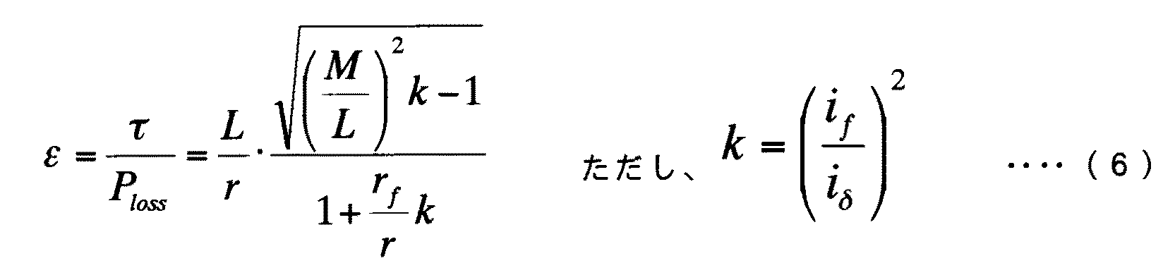
ただしLは電機子巻線の自己インダクタンス、Mは界磁巻線と電機子巻線の相互インダクタンスであり、電機子巻線の自己インダクタンスは回転子位置により変化しない、すなわちLの突極性はないものとする。先に述べたようにトルクは(3)式で、同期機の損失は(4)式で表される。この時、トルクと損失の比であるトルク損失比εは次式で表される。 However, L is the self-inductance of the armature winding, M is the mutual inductance of the field winding and the armature winding, and the self-inductance of the armature winding does not change depending on the rotor position, that is, there is no saliency of L Shall. As described above, the torque is expressed by equation (3), and the loss of the synchronous machine is expressed by equation (4). At this time, the torque loss ratio ε, which is the ratio of torque to loss, is expressed by the following equation.
このトルク損失比εを最大にするk=koptにおいて、トルク損失比εをkで偏微分した値は0になり、この条件の数式を整理すると次式が得られる。 At k = kopt that maximizes the torque loss ratio ε, the value obtained by partial differentiation of the torque loss ratio ε with respect to k is 0.
(7)式より分かるように、トルク損失比が最大、すなわち損失が最小となる条件では、(7)式で求められるkに相当する、電機子電流と界磁電流の比によって同期機は運転されている。
実際の同期機では、Lの突極性や鉄損の影響により、損失最小となる点は(7)式の条件と完全に一致するわけではないが、図4に示すように最小損失運転点付近では損失の変動は比較的緩やかであるので、(7)式により求めた運転点にちかい電流比で同期機を運転することにより、実用上十分な精度で損失最小となる運転を実現することができる。
As can be seen from the equation (7), under the condition that the torque loss ratio is the maximum, that is, the loss is the minimum, the synchronous machine is operated by the ratio of the armature current and the field current corresponding to k obtained by the equation (7). Has been.
In an actual synchronous machine, the point where the loss is minimized due to the influence of L saliency and iron loss does not completely match the condition of equation (7), but as shown in FIG. Since the fluctuation of the loss is relatively gradual, it is possible to realize the operation that minimizes the loss with practically sufficient accuracy by operating the synchronous machine at the current ratio close to the operating point obtained by the equation (7). it can.
図5に、以上に述べた動作を行う場合の電圧指令発生器の構造を示す。電機子電流に相当するδ軸電流指令iδ*はゲイン19により増幅され、このゲイン19の大きさは、たとえば上記損失最小時のkoptの平方根に相当する値であってもよく、また実測により決定された所定の電流比でも良い。ゲイン倍されたδ軸電流指令iδ*と界磁電流指令if*は加算器20にて差分が計算される。制御器21は、この差分を演算して線間電圧指令va*を算出、出力し、これにより電機子電流と界磁電流の比がゲイン19の値に一致するように制御するもので、例えば積分器あるいはPI制御器である。
FIG. 5 shows the structure of the voltage command generator when performing the above-described operation. The δ-axis current command iδ * corresponding to the armature current is amplified by a
なお、(2)式および(5)式より分かるように、線間電圧指令を変化させることにより界磁電流が変化する割合は回転速度に逆比例するので、制御器21のゲインは回転速度に比例するようにしてもよく、このようにすると回転速度の影響を受けずに安定した電流比の制御を行うことができる。なお、界磁磁束に永久磁石磁束を併用している同期機では、磁束と電流の関係が(5)式と異なるので(7)式による電流比をそのまま適用することはできないが、永久磁石磁束を等価な界磁電流で考え、この永久磁石分の等価界磁電流と実際の界磁電流を加えた値を所望の電流比に調整するようにすれば、近似的に損失最小に近い状態で運転することができる。
As can be seen from the equations (2) and (5), the rate at which the field current changes by changing the line voltage command is inversely proportional to the rotational speed, so the gain of the
実施の形態3.
図6は、実施の形態3における巻線界磁式同期機のベクトル制御装置を示す構成図である。この制御装置は、電圧制御を行わない従来の同期機の制御装置に、軽負荷時の効率を改善する機能を加えたものである。図において1〜17は実施の形態1と同じである。磁束指令発生器24は、電機子電流指令iδ*および界磁電流指令if*より同期機の損失を計算し、この損失が最小となるような磁束指令Φ*を発生する。(2)式より同期機の磁束を操作することにより電機子電圧を操作できることは自明であるので、磁束指令Φ*を操作しても実施の形態2と同様の損失最小運転を実現することができる。
FIG. 6 is a block diagram showing a vector control device of a winding field type synchronous machine in the third embodiment. This control device is obtained by adding a function for improving efficiency at light load to a control device for a conventional synchronous machine that does not perform voltage control. In the figure, 1 to 17 are the same as those in the first embodiment. The magnetic
磁束指令発生器24は実施の形態2同様に同期機の損失が最小となる磁束指令を探索する動作、あるいは図5同様に電機子電流と界磁電流が所定の比率になるように磁束指令を操作する動作を行う。なお後者の構成を用いる場合には、磁束指令を変化させることによる界磁電流の変化はほぼ比例であるので、実施の形態2で説明したように制御器のゲインを回転速度に比例させる必要はない。なお、実施の形態1に上述した磁束指令発生器24を設け、電機子電流指令iδ*および界磁電流指令if*より同期機の損失を計算し、この損失が最小となるような磁束指令Φ*を発生するようにしてもよい。
The magnetic
微分器22は回転子位相θを微分して同期機の回転速度を求め、磁束指令上限発生器23は回転速度によって決定される磁束指令の最大値を求め、この値により磁束指令発生器24は発生する磁束指令Φ*の値を制限する。なお、磁束指令上限発生器23の出力は、非特許文献1などに示された従来の制御装置において、回転速度を参照して決定される磁束指令の値と同様であり、電機子電圧の飽和を防ぐために設定されるものである。
The
1 同期機 2 三相ドライブ回路
3 直流ドライブ回路 4 電機子電流センサ
5 界磁電流センサ 6 回転子位置センサ
7 磁束演算系 8 電機子電流制御系
9 加算器 10 磁束制御器
11 加算器 12 界磁電流制御器
13 演算器 14 加算器
15 電圧制御器 16 加算器
17 除算器 18 電圧指令発生器
19 ゲイン 20 加算器
21 制御器 22 微分器
23 磁束指令上限発生器 24 磁束指令発生器。
DESCRIPTION OF
Claims (3)
Priority Applications (5)
| Application Number | Priority Date | Filing Date | Title |
|---|---|---|---|
| JP2004095815A JP4053511B2 (en) | 2004-03-29 | 2004-03-29 | Vector controller for wound field synchronous machine |
| FR0550787A FR2868221B1 (en) | 2004-03-29 | 2005-03-25 | VECTOR CONTROL DEVICE OF EXCITATION WINDING TYPE SYNCHRONOUS MACHINE |
| DE102005014138A DE102005014138A1 (en) | 2004-03-29 | 2005-03-29 | Vector control device of a winding field synchronous machine |
| US11/091,395 US7145311B2 (en) | 2004-03-29 | 2005-03-29 | Vector control device of winding field type synchronous machine |
| FR0551759A FR2872971B1 (en) | 2004-03-29 | 2005-06-24 | VECTOR CONTROL DEVICE OF EXCITATION WINDING TYPE SYNCHRONOUS MACHINE |
Applications Claiming Priority (1)
| Application Number | Priority Date | Filing Date | Title |
|---|---|---|---|
| JP2004095815A JP4053511B2 (en) | 2004-03-29 | 2004-03-29 | Vector controller for wound field synchronous machine |
Publications (2)
| Publication Number | Publication Date |
|---|---|
| JP2005287148A true JP2005287148A (en) | 2005-10-13 |
| JP4053511B2 JP4053511B2 (en) | 2008-02-27 |
Family
ID=34981108
Family Applications (1)
| Application Number | Title | Priority Date | Filing Date |
|---|---|---|---|
| JP2004095815A Expired - Fee Related JP4053511B2 (en) | 2004-03-29 | 2004-03-29 | Vector controller for wound field synchronous machine |
Country Status (4)
| Country | Link |
|---|---|
| US (1) | US7145311B2 (en) |
| JP (1) | JP4053511B2 (en) |
| DE (1) | DE102005014138A1 (en) |
| FR (2) | FR2868221B1 (en) |
Cited By (7)
| Publication number | Priority date | Publication date | Assignee | Title |
|---|---|---|---|---|
| JP2012131293A (en) * | 2010-12-20 | 2012-07-12 | Honda Motor Co Ltd | Brake system for vehicle |
| JP5456873B1 (en) * | 2012-11-30 | 2014-04-02 | 三菱電機株式会社 | Synchronous machine controller |
| US9847744B2 (en) | 2014-10-21 | 2017-12-19 | Denso Corporation | Controller and control method for rotary electric machine |
| JP2018121523A (en) * | 2018-04-13 | 2018-08-02 | キヤノン株式会社 | Motor control device and image forming apparatus |
| JP2019213396A (en) * | 2018-06-07 | 2019-12-12 | 株式会社デンソー | Rotary electric machine for vehicle |
| US10602009B2 (en) | 2016-05-31 | 2020-03-24 | Canon Kabushiki Kaisha | Motor control apparatus, sheet conveyance apparatus, and image forming apparatus |
| KR20210007620A (en) * | 2019-07-12 | 2021-01-20 | 주식회사 대흥기전 | Double field winding brushless synchronous generator removing distortion of output |
Families Citing this family (4)
| Publication number | Priority date | Publication date | Assignee | Title |
|---|---|---|---|---|
| JP5120586B2 (en) * | 2005-06-28 | 2013-01-16 | 株式会社デンソー | Field winding type synchronous machine |
| DE102006007610A1 (en) * | 2006-02-14 | 2007-08-16 | Brose Fahrzeugteile Gmbh & Co. Kommanditgesellschaft, Coburg | Drive device for an adjusting device for adjusting a vehicle part and method for operating a drive device |
| US7880424B2 (en) * | 2006-09-28 | 2011-02-01 | Denso Corporation | Rotary electric apparatus having rotor with field winding inducing current therethrough for generating magnetic field |
| DE102011089544A1 (en) * | 2011-12-22 | 2012-11-22 | Continental Automotive Gmbh | Method for determining corrected rotational angle of rotor of three-phase synchronous motor in e.g. hybrid vehicle, involves determining deviation signal, and determining corrected angle based upon current angle and deviation signal |
Family Cites Families (5)
| Publication number | Priority date | Publication date | Assignee | Title |
|---|---|---|---|---|
| US4549122A (en) * | 1983-09-14 | 1985-10-22 | Allen-Bradley Company | Method and circuit for DC motor field regulation with speed feedback |
| JP2856950B2 (en) * | 1991-07-22 | 1999-02-10 | 株式会社東芝 | Control device for synchronous motor |
| JP3473178B2 (en) * | 1995-05-31 | 2003-12-02 | 株式会社明電舎 | Control device for rotating electric machine |
| JP3899668B2 (en) * | 1998-04-28 | 2007-03-28 | 株式会社デンソー | Drive control device for field winding synchronous machine |
| US6731098B1 (en) * | 2000-10-24 | 2004-05-04 | Kohler Co. | Method and apparatus for sensing variable currents within the alternator of a genset that employs an amplifier and a switched feedback resistance |
-
2004
- 2004-03-29 JP JP2004095815A patent/JP4053511B2/en not_active Expired - Fee Related
-
2005
- 2005-03-25 FR FR0550787A patent/FR2868221B1/en not_active Expired - Fee Related
- 2005-03-29 US US11/091,395 patent/US7145311B2/en active Active
- 2005-03-29 DE DE102005014138A patent/DE102005014138A1/en not_active Withdrawn
- 2005-06-24 FR FR0551759A patent/FR2872971B1/en not_active Expired - Fee Related
Cited By (9)
| Publication number | Priority date | Publication date | Assignee | Title |
|---|---|---|---|---|
| JP2012131293A (en) * | 2010-12-20 | 2012-07-12 | Honda Motor Co Ltd | Brake system for vehicle |
| JP5456873B1 (en) * | 2012-11-30 | 2014-04-02 | 三菱電機株式会社 | Synchronous machine controller |
| US9847744B2 (en) | 2014-10-21 | 2017-12-19 | Denso Corporation | Controller and control method for rotary electric machine |
| US10602009B2 (en) | 2016-05-31 | 2020-03-24 | Canon Kabushiki Kaisha | Motor control apparatus, sheet conveyance apparatus, and image forming apparatus |
| JP2018121523A (en) * | 2018-04-13 | 2018-08-02 | キヤノン株式会社 | Motor control device and image forming apparatus |
| JP2019213396A (en) * | 2018-06-07 | 2019-12-12 | 株式会社デンソー | Rotary electric machine for vehicle |
| JP7192258B2 (en) | 2018-06-07 | 2022-12-20 | 株式会社デンソー | Rotating electric machine for vehicle |
| KR20210007620A (en) * | 2019-07-12 | 2021-01-20 | 주식회사 대흥기전 | Double field winding brushless synchronous generator removing distortion of output |
| KR102293663B1 (en) | 2019-07-12 | 2021-08-26 | 주식회사 대흥기전 | Double field winding brushless synchronous generator removing distortion of output |
Also Published As
| Publication number | Publication date |
|---|---|
| US7145311B2 (en) | 2006-12-05 |
| JP4053511B2 (en) | 2008-02-27 |
| FR2868221B1 (en) | 2011-08-12 |
| FR2872971A1 (en) | 2006-01-13 |
| FR2872971B1 (en) | 2011-08-12 |
| FR2868221A1 (en) | 2005-09-30 |
| US20050212476A1 (en) | 2005-09-29 |
| DE102005014138A1 (en) | 2005-10-27 |
Similar Documents
| Publication | Publication Date | Title |
|---|---|---|
| JP5130031B2 (en) | Position sensorless control device for permanent magnet motor | |
| JP5957704B2 (en) | Electric motor control device | |
| JP5357232B2 (en) | Synchronous machine controller | |
| JP4531751B2 (en) | Synchronous machine controller | |
| CN107078674B (en) | Control device for inverter and motor driven systems | |
| US7145311B2 (en) | Vector control device of winding field type synchronous machine | |
| JP5445892B2 (en) | Control device for permanent magnet type synchronous motor | |
| US9660560B2 (en) | Motor drive circuit and method of driving a motor | |
| WO2014057575A1 (en) | Synchronous machine control device | |
| JP2003061386A (en) | Synchronous motor drive system | |
| JP2009136085A (en) | Controller of ac motor | |
| JP2009124811A (en) | Control device of permanent magnet type synchronous motor | |
| JP2010213512A (en) | Torque controller for permanent-magnet synchronous motor | |
| WO2015056541A1 (en) | Drive device for electric motor | |
| JP5276688B2 (en) | Synchronous machine controller | |
| JP4652176B2 (en) | Control device for permanent magnet type rotating electrical machine | |
| JP5788057B1 (en) | Synchronous machine controller | |
| JP5050387B2 (en) | Motor control device | |
| US11837982B2 (en) | Rotary machine control device | |
| JP3622547B2 (en) | Control device for synchronous motor | |
| CN109302109B (en) | Flux weakening control method and control device for permanent magnet synchronous motor | |
| JP3715276B2 (en) | Stepping motor drive device | |
| JPH06225574A (en) | Method and apparatus for controlling motor | |
| CN116134723A (en) | Motor core loss calculation device and motor control device having the same | |
| JP5479094B2 (en) | Synchronous motor control method and control apparatus |
Legal Events
| Date | Code | Title | Description |
|---|---|---|---|
| A621 | Written request for application examination |
Free format text: JAPANESE INTERMEDIATE CODE: A621 Effective date: 20050729 |
|
| A977 | Report on retrieval |
Free format text: JAPANESE INTERMEDIATE CODE: A971007 Effective date: 20070306 |
|
| A131 | Notification of reasons for refusal |
Free format text: JAPANESE INTERMEDIATE CODE: A131 Effective date: 20070403 |
|
| A521 | Written amendment |
Free format text: JAPANESE INTERMEDIATE CODE: A523 Effective date: 20070511 |
|
| TRDD | Decision of grant or rejection written | ||
| A01 | Written decision to grant a patent or to grant a registration (utility model) |
Free format text: JAPANESE INTERMEDIATE CODE: A01 Effective date: 20071127 |
|
| A61 | First payment of annual fees (during grant procedure) |
Free format text: JAPANESE INTERMEDIATE CODE: A61 Effective date: 20071205 |
|
| FPAY | Renewal fee payment (event date is renewal date of database) |
Free format text: PAYMENT UNTIL: 20101214 Year of fee payment: 3 |
|
| R151 | Written notification of patent or utility model registration |
Ref document number: 4053511 Country of ref document: JP Free format text: JAPANESE INTERMEDIATE CODE: R151 |
|
| FPAY | Renewal fee payment (event date is renewal date of database) |
Free format text: PAYMENT UNTIL: 20101214 Year of fee payment: 3 |
|
| FPAY | Renewal fee payment (event date is renewal date of database) |
Free format text: PAYMENT UNTIL: 20111214 Year of fee payment: 4 |
|
| FPAY | Renewal fee payment (event date is renewal date of database) |
Free format text: PAYMENT UNTIL: 20111214 Year of fee payment: 4 |
|
| FPAY | Renewal fee payment (event date is renewal date of database) |
Free format text: PAYMENT UNTIL: 20121214 Year of fee payment: 5 |
|
| FPAY | Renewal fee payment (event date is renewal date of database) |
Free format text: PAYMENT UNTIL: 20121214 Year of fee payment: 5 |
|
| FPAY | Renewal fee payment (event date is renewal date of database) |
Free format text: PAYMENT UNTIL: 20131214 Year of fee payment: 6 |
|
| R250 | Receipt of annual fees |
Free format text: JAPANESE INTERMEDIATE CODE: R250 |
|
| R250 | Receipt of annual fees |
Free format text: JAPANESE INTERMEDIATE CODE: R250 |
|
| R250 | Receipt of annual fees |
Free format text: JAPANESE INTERMEDIATE CODE: R250 |
|
| R250 | Receipt of annual fees |
Free format text: JAPANESE INTERMEDIATE CODE: R250 |
|
| LAPS | Cancellation because of no payment of annual fees |