JP2005285557A - Flat battery and its manufacturing method - Google Patents
Flat battery and its manufacturing method Download PDFInfo
- Publication number
- JP2005285557A JP2005285557A JP2004097832A JP2004097832A JP2005285557A JP 2005285557 A JP2005285557 A JP 2005285557A JP 2004097832 A JP2004097832 A JP 2004097832A JP 2004097832 A JP2004097832 A JP 2004097832A JP 2005285557 A JP2005285557 A JP 2005285557A
- Authority
- JP
- Japan
- Prior art keywords
- thin battery
- electrode body
- battery
- spacer
- laminate film
- Prior art date
- Legal status (The legal status is an assumption and is not a legal conclusion. Google has not performed a legal analysis and makes no representation as to the accuracy of the status listed.)
- Pending
Links
Images


Classifications
-
- Y—GENERAL TAGGING OF NEW TECHNOLOGICAL DEVELOPMENTS; GENERAL TAGGING OF CROSS-SECTIONAL TECHNOLOGIES SPANNING OVER SEVERAL SECTIONS OF THE IPC; TECHNICAL SUBJECTS COVERED BY FORMER USPC CROSS-REFERENCE ART COLLECTIONS [XRACs] AND DIGESTS
- Y02—TECHNOLOGIES OR APPLICATIONS FOR MITIGATION OR ADAPTATION AGAINST CLIMATE CHANGE
- Y02E—REDUCTION OF GREENHOUSE GAS [GHG] EMISSIONS, RELATED TO ENERGY GENERATION, TRANSMISSION OR DISTRIBUTION
- Y02E60/00—Enabling technologies; Technologies with a potential or indirect contribution to GHG emissions mitigation
- Y02E60/10—Energy storage using batteries
-
- Y—GENERAL TAGGING OF NEW TECHNOLOGICAL DEVELOPMENTS; GENERAL TAGGING OF CROSS-SECTIONAL TECHNOLOGIES SPANNING OVER SEVERAL SECTIONS OF THE IPC; TECHNICAL SUBJECTS COVERED BY FORMER USPC CROSS-REFERENCE ART COLLECTIONS [XRACs] AND DIGESTS
- Y02—TECHNOLOGIES OR APPLICATIONS FOR MITIGATION OR ADAPTATION AGAINST CLIMATE CHANGE
- Y02P—CLIMATE CHANGE MITIGATION TECHNOLOGIES IN THE PRODUCTION OR PROCESSING OF GOODS
- Y02P70/00—Climate change mitigation technologies in the production process for final industrial or consumer products
- Y02P70/50—Manufacturing or production processes characterised by the final manufactured product
Abstract
Description
本発明は、薄型電池及びその製造方法に関し、更に詳しくは、ラミネート外装を使用した均質で厚みのばらつきの少ない薄型電池及びその製造方法に関する。 The present invention relates to a thin battery and a method for manufacturing the same, and more particularly, to a thin battery having a uniform and less variation in thickness using a laminate sheath and a method for manufacturing the same.
携帯型の電子機器の急速な普及に伴い、それに使用される電池への要求仕様は、年々厳しくなり、特に小型・薄型化、高容量でサイクル特性が優れ、性能の安定したものが要求されている。そして、二次電池分野では他の電池に比べて高エネルギー密度であるリチウム非水電解質二次電池が注目され、このリチウム非水電解質二次電池の占める割合は二次電池市場において大きな伸びを示している。 With the rapid spread of portable electronic devices, the required specifications for the batteries used for them are becoming stricter year by year, and in particular, small and thin, high capacity, excellent cycle characteristics, and stable performance are required. Yes. In the field of secondary batteries, lithium non-aqueous electrolyte secondary batteries, which have a higher energy density than other batteries, are attracting attention, and the proportion of lithium non-aqueous electrolyte secondary batteries shows a significant increase in the secondary battery market. ing.
このリチウム非水電解質二次電池は、図4に示すように、細長いシート状の銅箔等からなる負極芯体(集電体)の両面に負極用活物質合剤を被膜状に塗布した負極と、細長いシート状のアルミニウム箔等からなる正極芯体の両面に正極用活物質合剤を被膜状に塗布した正極との間に、微多孔性ポリプロピレンフィルム等からなるセパレータを配置し、負極及び正極をセパレータにより互いに絶縁した状態で円柱状又は楕円形状に巻回した後、角型電池の場合は更に巻回電極体を押し潰して偏平状の巻回電極体11を形成し、正極及び負極の各所定部分にそれぞれ正極集電端子12及び負極集電端子13を接続して所定形状の外装内(図示せず)に収納した構成を有している。
As shown in FIG. 4, this lithium non-aqueous electrolyte secondary battery is a negative electrode in which a negative electrode active material mixture is applied in a film form on both sides of a negative electrode core (current collector) made of a long sheet-like copper foil or the like. A separator made of a microporous polypropylene film or the like is disposed between the positive electrode in which a positive electrode active material mixture is coated on both sides of a positive electrode core made of a long sheet-like aluminum foil, and the like. After winding the positive electrode in a cylindrical or elliptical shape in a state of being insulated from each other by a separator, in the case of a square battery, the wound electrode body is further crushed to form a flat
このようなリチウム非水電解質二次電池の薄型化、軽量化及び折り曲げ可能となす目的で、外装としてラミネート外装体を備えた薄型のラミネート電池(以下、「薄型電池」という。)も開発されている(下記特許文献1〜3参照)。 In order to make the lithium non-aqueous electrolyte secondary battery thinner, lighter and bendable, a thin laminated battery (hereinafter referred to as “thin battery”) having a laminated outer package as an outer package has also been developed. (See Patent Documents 1 to 3 below).
以下、図5を用いて従来から慣用的に行われている薄型電池40の製造工程について説明する。まず最初に、図4に示したように、前述の従来例と同様にして偏平状の巻回電極体11を製造する。続いて、図5(a)に示したように、所定の大きさの周知のラミネートフィルム14、例えばアルミニウムラミネートフィルムを2つ折り(カップ成型)し、この内部に前記偏平な巻回電極体11を配置し、正極集電端子12及び負極集電端子13の導出部の両面に薄い集電端子溶着樹脂材15、16を配置した後、このラミネートフィルム14のトップ部(集電端子側)を加熱されたバー状の金型17を用いて定位方式に制御して溶着し、トップ封止部18を形成する。なお、この際、トップ封止部18の外縁には、ラミネートフィルム14から溶けたシーラント層がはみ出して金型に付着しないようにするため、未溶着部19が設けられている。
Hereinafter, the manufacturing process of the
次に、図5(b)に示したように、加熱されたバー状の金型20を用いて、ラミネートフィルム14のサイド部の一方側を溶着して第1のサイド封止部21を形成する。この場合も第1のサイド封止部21の外縁はラミネートフィルムから溶けたシーラント層がはみ出して金型に付着しないようにするため、未溶着部22が設けられている。次いで、液状電解質をもう一方のサイド部側から注入する。そうすると、この液状電解質は、偏平な巻回電極体11の内部へ十分に浸透する。
Next, as shown in FIG. 5B, the first
その後、図5(c)に示したように、ラミネートフィルム14の他方のサイド部側を加熱されたバー状の金型23により仮溶着して仮封止部24を形成する。次いで、必要に応じて液状電解質をゲル化し、予備充電及びエージングした後、図5(d)に示したように、ラミネートフィルム14の他方のサイド部側を加熱されたバー状の金型25で定位方式に制御して溶着して第2のサイド封止部26を形成する。そして、前記ラミネートフィルムの不要部を切断して、両方のサイド封止部21及び26を折り曲げ、図5(e)に示したような従来例の薄型電池40を得るものである。
Thereafter, as shown in FIG. 5C, the other side portion side of the
このようなラミネート外装を用いた薄型電池では、液状電解質を高分子重合体(ゲル状)に硬化させる場合、液状電解質を注液した後、十分に電極体内に浸透させるために電極体を外装体内で液状電解質に浸しておく必要があり、その状態では、電極が膨らんだ状態のため、液状電解質の硬化時に定位加圧もしくは定圧加圧することにより厚みを規制する必要がある。 In a thin battery using such a laminate outer package, when the liquid electrolyte is cured into a polymer (gel), the electrode body is placed in the outer package in order to sufficiently infiltrate the electrode body after the liquid electrolyte is injected. In this state, since the electrode is in a swelled state, it is necessary to regulate the thickness by applying a stereotaxic pressure or a constant pressure when the liquid electrolyte is cured.
定圧加圧の場合、薄型電池の厚みを必要とする一定の厚みにコントロールするためには、ある程度圧力を上げることが必要とされる。この場合、圧力を上げることで薄型電池の厚みを所定の一定値に規制することができるが、同時に電極体から液状電解質が押し出されてしまうので、正極及び負極間に存在する電解質量が減少して電池特性の低下が生じる可能性があった。 In the case of constant pressure pressurization, it is necessary to increase the pressure to some extent in order to control the thickness of the thin battery to a certain thickness. In this case, the thickness of the thin battery can be regulated to a predetermined constant value by increasing the pressure, but at the same time, the liquid electrolyte is pushed out from the electrode body, so that the electrolytic mass existing between the positive electrode and the negative electrode is reduced. Battery characteristics may be degraded.
一方、定位加圧で厚みを規制するには、薄型電池の機種ごとに対応が必要なため、大掛かりな設備が必要となってしまう。また、偏平な巻回電極体の厚みのバラツキにより過圧縮となることがあり、この場合には過剰の液状電解質が押し出されてしまい、定圧加圧の場合と同様に電池特性の低下が生じる可能性があった。 On the other hand, in order to regulate the thickness by stereotaxic pressure, it is necessary to deal with each type of thin battery, and thus a large facility is required. In addition, over-compression may occur due to variations in the thickness of the flat wound electrode body. In this case, excessive liquid electrolyte may be pushed out, and the battery characteristics may be reduced as in the case of constant-pressure pressurization. There was sex.
更に、液状電解質の硬化が終了した後、サイド側の封止部は薄型電池の幅寸法を最小限にするために偏平な巻回電極体を挿入しているカップ部に折り曲げた状態にもってくる必要があるが、偏平な巻回電極体とラミネートフィルムとの間の余剰空間にゲルが存在しているとサイド封止部の折り曲げ時に隙間から飛び出た余剰ゲルが偏平な巻回電極体に乗り上げるため、電池厚みがばらつく原因となり、また、この折り曲げ時に、折り曲げ位置が安定しないため、金属板などを挟み込み、その板を支点にして折り曲げる必要があるという問題点が存在していた。なお、上述の点は、液状電解質をゲル化させずにそのまま使用する場合においても同様に生じる問題である。 Further, after the liquid electrolyte has been cured, the side-side sealing portion is brought into a state of being folded into a cup portion into which a flat wound electrode body is inserted in order to minimize the width dimension of the thin battery. It is necessary, but if gel exists in the surplus space between the flat wound electrode body and the laminate film, the surplus gel that protrudes from the gap when the side sealing part is bent rides on the flat wound electrode body. For this reason, the thickness of the battery varies, and the folding position is not stable at the time of folding. Therefore, there is a problem that a metal plate or the like needs to be sandwiched and bent using the plate as a fulcrum. In addition, the above-mentioned point is the problem which arises similarly when using liquid electrolyte as it is, without gelatinizing.
本発明者は、上述のような従来技術の問題点を解決するために種々実験を繰り返した結果、偏平な巻回電極体の両側の側面部に該巻回電極体のサイド部の形状に沿ったスペーサを設けると、前述の従来技術の有する問題点を解決することができることを見出し、本発明を完成するに至ったのである。 As a result of repeating various experiments in order to solve the problems of the prior art as described above, the inventor follows the shape of the side portion of the spirally wound electrode body on the side surfaces on both sides of the flat spiral electrode body. It has been found that providing the spacers can solve the above-mentioned problems of the prior art, and the present invention has been completed.
なお、上記特許文献3には、薄型電池の耐衝撃性を向上させる目的で、図6に示したように、偏平な巻回電極体51の正極集電端子52と負極集電端子52側及びその反対側から、偏平な巻回電極体51の断面と同形状の樹脂製スペーサ54及び55を配置してラミネートフィルム(図示せず)内に前記偏平な巻回電極体51を封入して作製、ないしは、図7に示したように、ラミネートフィルムのある一面に電池を収容する空間56が形成されたラミネートフィルム57を使用し、その空間56内に偏平な巻回電極体51を収容し、その後硬化性樹脂を充填して硬化させた後にラミネートフィルム57を封止するようにして作製した薄型電池が開示されているが、偏平な巻回電極体51の両側のサイド部にスペーサを配置することは示されてはいない。
In Patent Document 3, for the purpose of improving the impact resistance of the thin battery, as shown in FIG. 6, the positive and negative current collecting
加えて、上記特許文献3に開示されている薄型電池は、負極及び正極の表面に予めポリマーを溶媒に溶解させた液状電解質を塗布した後、溶媒を気化させてゲル状電解質を形成し、その後に負極及び正極のゲル状電解質側を合わせて圧着することにより作製しているものであるため、ラミネートフィルム内に配置された偏平な巻回電極体51に液状の電解質を注入するという工程が存在しないので、前述のような従来技術の有する問題点は生じない。
In addition, in the thin battery disclosed in Patent Document 3, after applying a liquid electrolyte in which a polymer is dissolved in a solvent in advance to the surfaces of the negative electrode and the positive electrode, the solvent is vaporized to form a gel electrolyte, In other words, there is a step of injecting a liquid electrolyte into the flat
したがって、本発明は前記従来技術の有する問題点を解決するためになされたものであって、その第1の目的は、スペーサを有し、均一な品質の薄型電池を提供することにある。また、本発明の第2の目的は、スペーサを利用することにより、今まで困難であった偏平な巻回電極体内の保液量のコントロールと電池厚みのコントロールを同時に行うことができ、均一な品質の薄型電池を製造することができる薄型電池の製造方法を提供することにある。 Accordingly, the present invention has been made to solve the above-described problems of the prior art, and a first object thereof is to provide a thin battery having a uniform quality and having a spacer. In addition, the second object of the present invention is to use the spacer to simultaneously control the amount of liquid retained in the flat wound electrode body and the control of the battery thickness, which has been difficult until now, and is uniform. An object of the present invention is to provide a thin battery manufacturing method capable of manufacturing a quality thin battery.
本発明の第1の目的は以下の構成により達成し得る。すなわち、本願の請求項1に記載の薄型電池の発明は、正極及び負極がセパレータを挟んで積層された偏平状の巻回電極体と、非水電解質と、ラミネート外装体とからなる薄型電池において、前記偏平状の巻回電極体の両側のサイド部とラミネート外装体との間に所定の高さのスペーサを設けたことを特徴とする。この場合、薄型電池は、特にリチウム非水電解質二次電池に適用すると小型、軽量、かつ、長寿命で、出力が大きい薄型電池が得られるので好ましい。 The first object of the present invention can be achieved by the following configuration. That is, the invention of the thin battery according to claim 1 of the present application is a thin battery comprising a flat wound electrode body in which a positive electrode and a negative electrode are laminated with a separator interposed therebetween, a nonaqueous electrolyte, and a laminate outer package. A spacer having a predetermined height is provided between the side portions on both sides of the flat wound electrode body and the laminate exterior body. In this case, the thin battery is particularly preferable when applied to a lithium nonaqueous electrolyte secondary battery because a thin battery having a small size, light weight, long life, and high output can be obtained.
本願の請求項2に記載の発明は、前記請求項1に記載の薄型電池において、前記スペーサの前記電極体と対向する側の面は前記電極体のサイド部の形状に沿った形状を備えていることを特徴とする。前記スペーサは前記電極体のサイド部側のみに存在すれば良く、トップ部及びその反対側にスペーサを配置するかどうかは任意である。 The invention according to claim 2 of the present application is the thin battery according to claim 1, wherein the surface of the spacer facing the electrode body has a shape along the shape of the side portion of the electrode body. It is characterized by being. The spacer only needs to be present on the side portion side of the electrode body, and it is optional whether the spacer is disposed on the top portion or the opposite side.
本願の請求項3に記載の発明は、前記請求項1又は2に記載の薄型電池において、前記スペーサは、所定圧力が加えられた際に形状を保つことができる材料からなることを特徴とする。 The invention according to claim 3 of the present application is characterized in that, in the thin battery according to claim 1 or 2, the spacer is made of a material capable of maintaining a shape when a predetermined pressure is applied. .
また、本願の請求項4に記載の発明は、前記請求項3に記載の薄型電池において、前記スペーサの材料が、前記非水電解質と反応しない金属類、又は、ポリプロピレン等のポリオレフイン類、エポキシ樹脂、ポリエチレンテレフタレート樹脂、ポリスチレン樹脂、メラミン樹脂等の高分子材料の少なくとも1種類の樹脂から成ることを特徴とする。 The invention according to claim 4 of the present application is the thin battery according to claim 3, wherein the spacer material is a metal that does not react with the non-aqueous electrolyte, a polyolefin such as polypropylene, or an epoxy resin. It is characterized by comprising at least one kind of polymer material such as polyethylene terephthalate resin, polystyrene resin, melamine resin.
更に、本願の請求項5に記載の発明は、前記請求項1〜4のいずれかに記載の薄型電池において、前記非水電解質がゲル状であることを特徴とする。 Furthermore, the invention according to claim 5 of the present application is characterized in that, in the thin battery according to any one of claims 1 to 4, the nonaqueous electrolyte is in a gel form.
更に、本願の第2の目的は以下の構成により達成し得る。すなわち、本願の請求項6に記載の薄型電池の製造方法の発明は、以下の(1)〜(6)の工程からなることを特徴とする。
(1)正極集電端子及び負極集電端子を備え、正極及び負極がセパレータを挟んで積層された偏平状の巻回電極体を作製する工程、
(2)前記偏平状の巻回電極体の両サイド部に所定高さの一対のスペーサを配置して底部を2つ折りに折り曲げたラミネートフィルムの内部に挿入する工程、
(3)前記ラミネートフィルムのトップ部及び一方のサイド部を封止する工程、
(4)前記ラミネートフィルムの他方のサイド部から非水電解質を注入し、前記他方のサイド部を封止する工程、
(5)偏平面の上部から所定の一定圧力で押圧する工程、
(6)ガス抜き後に最終シールを行う工程。
Furthermore, the second object of the present application can be achieved by the following configuration. That is, the invention of the thin battery manufacturing method according to claim 6 of the present application is characterized by comprising the following steps (1) to (6).
(1) A step of producing a flat wound electrode body including a positive electrode current collecting terminal and a negative electrode current collecting terminal, wherein the positive electrode and the negative electrode are laminated with a separator interposed therebetween,
(2) A step of inserting a pair of spacers having a predetermined height on both side portions of the flat wound electrode body and inserting the bottom portion into a laminate film folded in half,
(3) A step of sealing the top portion and one side portion of the laminate film,
(4) Injecting a nonaqueous electrolyte from the other side portion of the laminate film, and sealing the other side portion;
(5) a step of pressing at a predetermined constant pressure from above the uneven plane;
(6) A step of performing a final seal after degassing.
また、本願の請求項7に記載の発明は、前記請求項6に記載の薄型電池の製造方法において、前記(4)の工程における非水電解質がモノマー成分及び重合開始剤を含有する液状のポリマー電解質前駆体であり、前記(5)の工程が偏平面の上部から所定の一定圧力で押圧しながら前記ポリマー電解質前駆体を重合させる工程であることを特徴とする。 The invention according to claim 7 of the present application is the method for producing a thin battery according to claim 6, wherein the nonaqueous electrolyte in the step (4) is a liquid polymer containing a monomer component and a polymerization initiator. It is an electrolyte precursor, and the step (5) is a step of polymerizing the polymer electrolyte precursor while being pressed from above the uneven plane with a predetermined constant pressure.
また、本願の請求項8に記載の発明は、前記請求項6又は7に記載の薄型電池の製造方法において、前記スペーサとして前記電極体と対向する側の面は前記電極体のサイド部の形状に沿った形状を有するものを用いたことを特徴とする。 The invention according to claim 8 of the present application is the thin battery manufacturing method according to claim 6 or 7, wherein the surface of the spacer facing the electrode body is the shape of the side portion of the electrode body. What used the shape which followed the shape was used.
また、本願の請求項9に記載の発明は、前記請求項6〜8のいずれかに記載の薄型電池の製造方法において、更に、前記サイド封止部を折り曲げる工程を備えることを特徴とする。 The invention according to claim 9 of the present application is characterized in that in the method of manufacturing a thin battery according to any of claims 6 to 8, the method further comprises a step of bending the side sealing portion.
本発明は上記の構成を備えることにより以下に述べるような優れた効果を奏する。すなわち、請求項1に記載の薄型電池によれば、偏平な巻回電極体の両側のサイド部とラミネート外装体との間に所定の高さのスペーサが存在しているため、薄型電極の表面が平らとなるだけでなく耐衝撃性に優れるようになる。 By providing the above configuration, the present invention has the following excellent effects. That is, according to the thin battery according to claim 1, since there are spacers of a predetermined height between the side portions on both sides of the flat wound electrode body and the laminate exterior body, the surface of the thin electrode Not only becomes flat, but also has excellent impact resistance.
また、請求項2に記載の薄型電池によれば、前記スペーサの前記電極体と対向する側の面は前記電極体のサイド部の形状に沿った形状を備えているので、サイド部のデッドスペースを小さくできるようになる。そのため、余剰空間がなくなるため電池の反応に寄与しない余剰の電解質の発生を低減でき、また、封止部を折り曲げても偏平な巻回電極体に乗り上げる電解質はないため、厚みバラツキを抑制することができる。 According to the thin battery of claim 2, since the surface of the spacer facing the electrode body has a shape along the shape of the side part of the electrode body, the dead space of the side part Can be reduced. Therefore, the generation of surplus electrolyte that does not contribute to the reaction of the battery can be reduced because there is no surplus space, and there is no electrolyte that climbs on the flat wound electrode body even if the sealing part is bent, thereby suppressing variation in thickness. Can do.
また、請求項3に記載の薄型電池によれば、前記スペーサは、所定圧力が加えられた際に形状を保つことができる材料からなるので、薄型電池の偏平な面側全体に力が加えられても、スペーサの存在によりそれ以上の変形が抑制されるため、一定の厚さを維持できるようになると共に、薄型電極が破損し難くなる。 According to the thin battery of claim 3, since the spacer is made of a material that can maintain its shape when a predetermined pressure is applied, a force is applied to the entire flat surface side of the thin battery. However, since the further deformation | transformation is suppressed by presence of a spacer, while being able to maintain fixed thickness, it becomes difficult to damage a thin electrode.
また、請求項4に記載の薄型電池によれば、容易に化学的に安定で所定の強度を有するスペーサが得られる。 In addition, according to the thin battery of the fourth aspect, it is possible to easily obtain a spacer that is chemically stable and has a predetermined strength.
また、請求項5に記載の薄型電池によれば、電解質がゲル状であるのでラミネート外装が破損した際に漏液が生じることが少なくなる。 Moreover, according to the thin battery of Claim 5, since electrolyte is a gel form, when a laminate exterior is damaged, it is less likely that liquid leakage occurs.
更に、請求項6に記載の薄型電池の製造方法によれば、偏平面の上部から所定の一定圧力で押圧するときにスペーサにより厚さが一定に保たれるため、偏平な巻回電極体に過剰な圧力がかかることがなくなり、薄型電極の厚さも一定にコントロールすることができると共に電極体内の保液量を一定にコントロールすることができ、均一な品質の薄型電池を製造することができるようになる。 Furthermore, according to the method for manufacturing a thin battery according to claim 6, since the thickness is kept constant by the spacer when pressed from above the flat surface with a predetermined constant pressure, the flat wound electrode body is formed. Excessive pressure is not applied, the thickness of the thin electrode can be controlled to be constant, and the amount of liquid retained in the electrode body can be controlled to be constant, so that a thin battery with uniform quality can be manufactured. become.
また、請求項7に記載の薄型電池の製造方法によれば、薄型電極の厚さを一定にコントロールしながらポリマー電解質前駆体をゲル化させることができるから、偏平な巻回電極体内の電解質量を一定にコントロールすることができ、均一な品質の薄型電池を製造することができるようになる。 In addition, according to the thin battery manufacturing method of claim 7, since the polymer electrolyte precursor can be gelled while the thickness of the thin electrode is controlled to be constant, the electrolytic mass in the flat wound electrode body can be reduced. Can be controlled to a certain level, and a thin battery of uniform quality can be manufactured.
また、請求項8に記載の薄型電池の製造方法によれば、容易に前記請求項2に記載の薄型電池を製造することができるようになる。 Moreover, according to the thin battery manufacturing method of claim 8, the thin battery of claim 2 can be easily manufactured.
また、請求項9に記載の薄型電池によれば、スペーサの存在のために、サイド封止部を折り曲げるときに、金属板などを挟み込まなくても、スペーサを支点にして容易に折り曲げることができるようになる。 Further, according to the thin battery of claim 9, due to the presence of the spacer, when the side sealing portion is bent, it can be easily bent using the spacer as a fulcrum without sandwiching a metal plate or the like. It becomes like this.
以下、本発明を実施するための最良の形態を実施例及び比較例を図1〜図3を用いて、更に必要に応じて従来例の図4及び図5をも参照しながら詳細に説明するが、理解を容易にするために、図4及び図5に示されている従来例の偏平型電池と同一の構成については同一の参照符号を付与して説明することとする。ただし、以下に示す実施例は本発明の技術思想を具体化するための薄型電池及びその製造方法を例示するものであって、本発明をこの実施例の薄型電池及びその製造方法に特定することを意図するものではなく、特許請求範囲に記載された技術的範囲に含まれるものに等しく適用し得るものである。 BEST MODE FOR CARRYING OUT THE INVENTION Hereinafter, the best mode for carrying out the present invention will be described in detail with reference to FIGS. 1 to 3 with reference to FIGS. However, in order to facilitate understanding, the same components as those of the conventional flat battery shown in FIGS. 4 and 5 will be described with the same reference numerals. However, the following examples illustrate the thin battery and the manufacturing method thereof for embodying the technical idea of the present invention, and the present invention is specified to the thin battery and the manufacturing method of this embodiment. And is equally applicable to those included in the technical scope described in the claims.
<偏平な巻回電極体の製造>
まず、実施例及び比較例に共通の偏平な巻回電極体の製造方法について説明する。正極に用いられる活物質としては、LiMn2O4に代表されるスピネル型マンガン酸リチウム及びLiCoO2に代表されるコバルト酸リチウムを一定量混合したものを用いた。正極極板は、前記正極活物質に炭素導電剤(例えばグラファイト)を所定量混合した後でフッ素樹脂系結着剤(例えばポリフッ化ビニリデン)と一定の割合で混合して正極合剤とし、アルミニウム箔の両面に塗着し、乾燥後圧延して極板とした。また、負極極板は炭素材(例えばリン片状天然黒鉛)とフッ素樹脂系結着剤を一定の割合で混合し、銅箔の両面に塗着した後、乾燥後圧延して極板とした。
<Manufacture of flat wound electrode body>
First, the manufacturing method of the flat wound electrode body common to an Example and a comparative example is demonstrated. As an active material used for the positive electrode, a mixture of a certain amount of spinel type lithium manganate typified by LiMn 2 O 4 and lithium cobaltate typified by LiCoO 2 was used. The positive electrode plate is prepared by mixing a predetermined amount of a carbon conductive agent (for example, graphite) with the positive electrode active material and then mixing it with a fluororesin binder (for example, polyvinylidene fluoride) at a certain ratio to obtain a positive electrode mixture. It was applied to both sides of the foil, dried and rolled to obtain an electrode plate. The negative electrode plate is made by mixing a carbon material (for example, flake shaped natural graphite) and a fluororesin-based binder at a certain ratio, coating the both surfaces of the copper foil, rolling it after drying, and forming the electrode plate. .
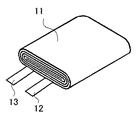
そして、図4に示したように、正極の最外周部分に該当する金属製芯体箔露出部に正極集電端子12を溶接すると共に、負極の外周部分に該当する金属製芯体箔露出部にも負極集電端子13を溶接し、これらの集電端子12及び13に表面には短絡防止等保護の目的でポリフェニレンサルファイド製のテープ(図示せず)を貼り付け、次いで、正極極板及び負極極板をポリエチレン製の多孔質セパレータを介して巻回状に巻き取り、押し潰して偏平な巻回電極体11を製造した。
And as shown in FIG. 4, while welding the positive electrode
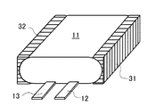
実施例の薄型電池は、次のようにして作製した。まず、高さ3.5mmの一組のポリプロピレン製スペーサ31及び32を用意し、図1に示したように、偏平な巻回電極体11の両サイド部に当接させた。この一組のスペーサ31及び32は、偏平な巻回電極体11のサイド部と対向する側の面が前記電極体11のサイド部の形状に沿った形状を備え、その反対側の面は巻回電極体11の偏平な面とは直角に伸びている。そうすると、このスペーサ31及び32と偏平な巻回電極体11との間には隙間がほとんど生じないようになる。なお、このスペーサとしては、ポリプロピレンに限らず、非水電解質と反応しない金属類、又は、ポリオレフィン類、エポキシ樹脂、ポリエチレンテレフタレート樹脂、ポリスチレン樹脂、メラミン樹脂等の高分子材料の少なくとも1種類の樹脂を適宜選択して使用し得る。
The thin battery of the example was manufactured as follows. First, a set of
この偏平状の巻回電極体11の両サイド部にスペーサ31及び32を当接させたまま、図5に示した従来例の偏平型電極の製造方法と同様の工程を経て実施例の偏平型電池を作製した。すなわち、偏平状の巻回電極体11の両サイド部にスペーサ31及び32を当接させたまま、図5(a)に示したように、カップ成型されたアルミラミネート外装14内に収納し、バー型の金型17を用いてトップ部を封止してトップ封止部18を形成した。使用したアルミラミネートフィルムの総厚は、約0.100mmであり、シーラント層の厚みは、約0.030mmであった。次いで、図5(b)に示したように、バー状の金型20を使用してアルミラミネートフィルムの一方のサイド側を封止してサイド封止部21を形成した。
While the
その後、エチレンカーボネート(EC)とジエチルカーボネート(DEC)を質量比でEC:DEC=3:7となるように混合した混合溶媒に六弗化リン酸リチウムLiPF6を1mol/lとなる割合で溶解して電解液を調製した。この電解液15質量部に対して下記化学式(1)で表されるポリプロピレングリコールジアクリレート又は下記化学式(2)で表されるポリピロビレングリコールジメタクリレート等の重合性化合物を1質量部混合した後、ビニレンカーボネートを1質量%となるように混合し、更に、重合開始剤としてt−ブチルペルオキシピバレートを5000ppm添加し、ポリマー前駆体とした。 Thereafter, lithium hexafluorophosphate LiPF 6 was dissolved at a rate of 1 mol / l in a mixed solvent in which ethylene carbonate (EC) and diethyl carbonate (DEC) were mixed so that the mass ratio was EC: DEC = 3: 7. Thus, an electrolytic solution was prepared. After mixing 1 part by mass of a polymerizable compound such as polypropylene glycol diacrylate represented by the following chemical formula (1) or polypyrylene glycol dimethacrylate represented by the following chemical formula (2) with respect to 15 parts by mass of the electrolytic solution. Then, vinylene carbonate was mixed so as to be 1% by mass, and 5000 ppm of t-butylperoxypivalate was further added as a polymerization initiator to obtain a polymer precursor.

このポリマー前駆体を先の巻回電極体を収納したアルミ外装体内に注液した後、図5(c)に示すように、他方のサイド部をバー状の金型23を用いて封止することにより仮封止部24を形成し、そのまま2.94×10²N(30kgf)の定圧で厚みを規制しながら60℃オーブン中に3時間静置し、ポリマー前駆体を重合・硬化させてポリマー電解質を形成した。その後、ガス抜きし、予備充電後に、図5(d)に示すように、他方のサイド部をバー状の金型25を用いて封止することにより封止部26を形成し、封止部21及び26の余分な部分を切り取った後に折り曲げて実施例の薄型電池を完成させた。この封止部の折り曲げ時には、スペーサ31及び32の角が支点となるため、容易に折り曲げることができた。この実施例の薄型電池の模式的正面図を図2に示す。この実施例の薄型電池10は、公称容量が830mAhであり、図2に示したように、偏平な巻回電極体11とラミネートフィルム14との間には余剰のゲルはほとんど見られず、また、折り曲げた封止部21及び26と薄型電池10の側面との間の隙間をほとんどなくすことができた。
After this polymer precursor is injected into the aluminum outer package containing the previous wound electrode body, the other side portion is sealed with a bar-shaped
(比較例1)
比較例1の薄型電池10aとしては、スペーサを偏平な巻回電極体に装着しない以外は、実施例の薄型電池と同様にして作製し、ポリマー電解質前駆体を熱硬化させる際に3.7mmの定位で厚みを規制することで電池を作製した。この比較例1の薄型電池の模式的正面図を図3に示す。この比較例1の薄型電池10aは、偏平な巻回電極体の四隅とラミネートフィルム14との間に余剰空間が生じており、この内部に余剰なゲル34が存在していた。そして、封止部21及び26を折り曲げる際には、下部の余剰なゲル34が存在している部分は柔らかいため、そのままでは一定の位置から折り曲げることはできなかったので、折り曲げ位置に金属板などの薄い板を押し当てることにより正確に折り曲げることができた。
(Comparative Example 1)
The
(比較例2)
比較例2の薄型電池としては、スペーサを偏平な巻回電極体に装着しない以外は、実施例の薄型電池と同様にして作製し、ポリマー電解質前駆体を熱硬化させる際に2.94×10²N(30kgf)の定圧で厚みを規制しながら薄型電池を作製した。この比較例2の薄型電池の模式的正面図は図3に示した比較例1の模式的正面図と同様であり、得られた比較例2の封止部21及び26の折り曲げに際する特徴も比較例1の薄型電池の場合と同様であった。
(Comparative Example 2)
The thin battery of Comparative Example 2 was prepared in the same manner as the thin battery of the Example except that the spacer was not attached to the flat wound electrode body, and 2.94 × 10 2 when the polymer electrolyte precursor was thermoset. A thin battery was produced while regulating the thickness with a constant pressure of 2 N (30 kgf). The schematic front view of the thin battery of Comparative Example 2 is the same as the schematic front view of Comparative Example 1 shown in FIG. 3, and the characteristics when the sealing
<組立後の電池厚みおよび電解液保持量の測定>
実施例、比較例1及び比較例2の組立直後の各電池について、それぞれ100個ずつ、電池の厚さをマイクロメータにより測定してその平均値を求めると共にその最小値及び最大値を求めた。また、質量測定により電解液保持量を求めた。その結果をまとめて表1に示す。なお、電池厚みの数値において、括弧外の数値は平均値を示し、括弧内の数値はそれぞれ最小値及び最大値を示す。
<Measurement of battery thickness and electrolyte retention after assembly>
For each of the batteries immediately after assembling in Example, Comparative Example 1 and Comparative Example 2, the thickness of each battery was measured with a micrometer to determine the average value and the minimum and maximum values. Moreover, the electrolyte solution holding | maintenance amount was calculated | required by mass measurement. The results are summarized in Table 1. In addition, in the numerical value of battery thickness, the numerical value outside parenthesis shows an average value, and the numerical value in parenthesis shows a minimum value and a maximum value, respectively.
<サイクル試験後の電池容量及び電池厚みの測定>
まず最初に、実施例、比較例1及び比較例2の各電池について、25℃において、1It=830mAの定電流で充電し、電池電圧が4.2Vに達した後は4.2Vの定電圧で充電電流が30mAとなるまで充電した。その後、10分間の休止時間を挟んで、1Itの定電流で電池電圧が2.75Vになるまで放電を行い、この充放電サイクルを1サイクルとして300サイクル繰り返した後、電池容量と電池の厚みを測定し、300サイクル時の電池容量及び電池厚みを求めた。更に、これらの300サイクル時の電池容量及び電池厚みを求めた電池について200サイクルの充放電サイクルを追加し、同様に電池容量と電池厚みを測定し、500サイクル時の電池容量及び電池厚みを求めた。結果をまとめて表1に示す。
<Measurement of battery capacity and thickness after cycle test>
First, the batteries of Examples, Comparative Example 1 and Comparative Example 2 were charged at a constant current of 1 It = 830 mA at 25 ° C., and after the battery voltage reached 4.2 V, the constant voltage of 4.2 V was charged. The battery was charged until the charging current reached 30 mA. Thereafter, the battery is discharged at a constant current of 1 It until the battery voltage reaches 2.75 V with a 10-minute rest period, and this charge / discharge cycle is repeated as 300 cycles, and then the battery capacity and battery thickness are determined. The battery capacity and battery thickness at 300 cycles were determined. Furthermore, about the battery which calculated | required the battery capacity and battery thickness at the time of these 300 cycles, the charging / discharging cycle of 200 cycles was added, battery capacity and battery thickness were measured similarly, and the battery capacity and battery thickness at the time of 500 cycles were calculated | required. It was. The results are summarized in Table 1.
表1の結果から以下のことが分かる。すなわち、電池の厚みはバラツキを考慮して顧客から要望される電池厚みになるようにする必要があるが、スペーサを用いた実施例の薄型電池は、スペーサで厚みを規制することができるため、厚みのばらつきが非常に小さく、狙いどおりの厚さの薄型電池が得られている。これに対し比較例1の薄型電池は、定位で厚みの規制を行っているために、各電池の厚みの平均値は実施例と同等レベルになっているが、厚みのバラツキは実施例のものよりも若干大きい結果となっている。また、比較例2の薄型電池は、定圧による厚み規制を行っているのにスペーサが存在しないため、電池の厚みは個々の電池ごとに大きく変化するのでばらつきは非常に大きく、個々の電池の厚みコントロールは不可能となっている。このことから電池厚みのバラツキが少なくなるような圧力を印加する必要が生じるため、圧力は高めの設定になってしまい、電池厚みの薄いものができてしまう。 From the results in Table 1, the following can be understood. That is, the thickness of the battery needs to be the battery thickness requested by the customer in consideration of variations, but the thin battery of the embodiment using the spacer can regulate the thickness with the spacer, The variation in thickness is very small, and a thin battery with the desired thickness is obtained. On the other hand, since the thickness of the thin battery of Comparative Example 1 is regulated by the localization, the average value of the thickness of each battery is the same level as in the example, but the thickness variation is that of the example. The result is slightly larger than that. In addition, since the thin battery of Comparative Example 2 does not have a spacer even though the thickness is regulated by constant pressure, the thickness of the battery varies greatly from one battery to another, so the variation is very large. Control is impossible. As a result, it is necessary to apply a pressure that reduces the variation in battery thickness, so that the pressure is set to a high setting, and a battery having a small thickness is produced.
また、電池厚みのバラツキの要因には、余剰空間に存在するゲル34が、電池のサイド封止部の折り曲げ時に電極体の表面に乗り上げることによるものがある。実施例の薄型電池は、スペーサ31及び32により余剰空間にゲルは存在しないため、これによる厚みバラツキはないが、比較例1及び2の薄型電池では余剰空間にゲル34が存在するため、厚みバラツキの要因となる。
Moreover, the cause of the variation in battery thickness is that the
なお、電池内保液量は、比較例1の薄型電池のものは実施例のものよりも多いが、比較例2のものは実施例のものよりも小さくなっている。また、サイクル試験の結果によれば、比較例1の薄型電池は、300サイクル後及び500サイクル後においても、電池容量及び厚みとも実施例のものと同程度の特性が得られている。これに対し、比較例2の薄型電池は、300サイクル後の容量及び厚みは実施例のものと同等の特性が得られているが、500サイクル後の容量は実施例1及び比較例1のものの約1/3と大幅に低下し、また、電池厚みも大幅に大きくなっている。 The amount of liquid retained in the battery is larger in the thin battery of Comparative Example 1 than in the Example, but smaller in Comparative Example 2 than in the Example. Further, according to the results of the cycle test, the thin battery of Comparative Example 1 has the same characteristics as those of the examples in both battery capacity and thickness after 300 cycles and 500 cycles. In contrast, the thin battery of Comparative Example 2 has the same capacity and thickness after 300 cycles as those of the Example, but the capacity after 500 cycles is that of Example 1 and Comparative Example 1. It is significantly reduced to about 1/3, and the battery thickness is also greatly increased.
このことは、実施例の薄型電池では、スペーサによる余剰空間の削減により、過剰なゲルの存在はなく、特性に必要な適量となっていることを示すものである。これに対し、比較例1の薄型電池では、余剰空間が存在するため特性に必要な量以上の保液量となっており、これがサイクル試験の良好な結果につながったものである。なお、比較例2の薄型電池では保液量が実施例のものよりも小さくなっているが、これは電池作製時に過剰な圧力が掛かったために、偏平な巻回電極体内の電解液が押し出され、必要量より少なくなる結果となったものである。そのため、比較例2の薄型電池では、電池内保液量が少ないことによる影響で、300サイクルを超えると急激な特性低下を示している。 This indicates that in the thin battery of the example, there is no excessive gel due to the reduction of the excess space by the spacer, and the amount is appropriate for the characteristics. On the other hand, in the thin battery of Comparative Example 1, since the surplus space exists, the liquid retention amount is more than the amount necessary for the characteristics, which leads to a good result of the cycle test. In the thin battery of Comparative Example 2, the amount of liquid retained was smaller than that of the example, but this was because excessive pressure was applied at the time of battery production, so that the electrolyte in the flat wound electrode body was pushed out. The result is less than the required amount. For this reason, the thin battery of Comparative Example 2 shows an abrupt deterioration in characteristics over 300 cycles due to the small amount of liquid retained in the battery.
上記結果より、本発明のスペーサを用いることで、電池厚みと保液量のコントロールが可能となり、各比較例と比べても電池寸法のばらつきが少なく、しかも優れた充放電特性を有する薄型電池を作製することができた。また、定圧制御による加圧装置は定位制御による加圧装置よりも構成が簡単で安価であるため、設備の簡略化及び原価削減につながり、更には使用する電解液量削減によるコストダウンの効果も生じる。 From the above results, by using the spacer of the present invention, it is possible to control the battery thickness and the amount of liquid retained, and there is less variation in battery dimensions compared to each comparative example, and a thin battery having excellent charge / discharge characteristics. We were able to make it. In addition, the pressurization device by constant pressure control is simpler and less expensive than the pressurization device by localization control, leading to simplification of equipment and cost reduction, as well as cost reduction effect by reducing the amount of electrolyte used. Arise.
なお、本実施例では、特定の正極活物質、負極活物質、非水溶媒、モノマー、重合開始剤等を使用したものを例示したが、本発明は、偏平状の巻回電極体と、所定の高さのスペーサと、ラミネートフィルムから成る外装体とを用いることを発明を特定するために必要とする事項とする発明であるから、その他の電池内の材料構成について周知のものを適宜選択して使用し得る。 In the present example, a specific positive electrode active material, a negative electrode active material, a non-aqueous solvent, a monomer, a polymerization initiator, and the like are exemplified. However, the present invention provides a flat wound electrode body, In order to specify the invention, it is necessary to use a spacer having a height of 5 mm and an exterior body made of a laminate film. Can be used.
すなわち、正極活物質としては、マンガン酸リチウム及びコバルト酸リチウムの混合物だけでなく、LixMO2(但し、MはCo、Ni、Mnの少なくとも1種である)で表されるリチウム遷移金属複合酸化物、すなわちLiCoO2、LiNiO2、LiNiyCo1−yO2(y=0.01〜0.99)、LiMnO2、LiCoxMnyNizO2(x+y+z=1)などや、LiMn2O4で表されるスピネル型コバルト酸リチウムが一種単独もしくは複数種を混合して用いられてもよく、正極活物質中に少量のジルコニウム(Zr)、チタニウム(Ti)及び弗素(F)等の異種元素を添加されていてもよい。 That is, as the positive electrode active material, not only a mixture of lithium manganate and lithium cobaltate but also a lithium transition metal composite represented by Li x MO 2 (where M is at least one of Co, Ni, and Mn). oxide, i.e. LiCoO 2, LiNiO 2, LiNi y Co 1-y O 2 (y = 0.01~0.99), LiMnO 2, LiCo x Mn y Ni z O 2 (x + y + z = 1) or the like, LiMn Spinel type lithium cobalt oxide represented by 2 O 4 may be used singly or as a mixture of plural kinds, and a small amount of zirconium (Zr), titanium (Ti), fluorine (F), etc. in the positive electrode active material These different elements may be added.
また、負極に使用する負極活物質には、リチウムを吸蔵・放出することが可能な炭素質物、珪素質物、金属酸化物からなる群から選択される少なくとも1種以上が用いられてもよい。黒鉛化の進んだ炭素質物は高容量であるために特に好ましい。 In addition, as the negative electrode active material used for the negative electrode, at least one selected from the group consisting of a carbonaceous material capable of inserting and extracting lithium, a siliconaceous material, and a metal oxide may be used. A carbonaceous material that has been graphitized is particularly preferable because of its high capacity.
前記非水電解質を構成する非水溶媒(有機溶媒)は、ECとDECの混合溶媒のみでなく、カーボネート類、ラクトン類、エーテル類、エステル類、芳香族炭化水素などが挙げられ、これらの中でカーボネート類、ラクトン類、エーテル類、ケトン類、エステル類などが好ましく、カーボネート類が更に好適に用い得る。 Nonaqueous solvents (organic solvents) constituting the nonaqueous electrolyte include not only mixed solvents of EC and DEC, but also carbonates, lactones, ethers, esters, aromatic hydrocarbons, and the like. Carbonates, lactones, ethers, ketones, esters and the like are preferable, and carbonates can be used more suitably.
カーボネート類として具体的には、環状カーボネート類として、プロピレンカーボネート(PC)、エチレンカーボネート(EC)、ブチレンカーボネート(BC)から選ばれる少なくとも1種以上が好ましく、鎖状カーボネート類(非環状カーボネート類)として、ジメチルカーボネート(DMC)、エチルメチルカーボネート(EMC)、ジエチルカーボネート(DEC)から選ばれる少なくとも1種以上が好ましい。 Specifically, the carbonates are preferably at least one selected from propylene carbonate (PC), ethylene carbonate (EC), and butylene carbonate (BC) as cyclic carbonates, and chain carbonates (acyclic carbonates). As at least 1 sort (s) chosen from dimethyl carbonate (DMC), ethyl methyl carbonate (EMC), and diethyl carbonate (DEC) is preferable.
非水電解質を構成する電解質は、過塩素酸リチウム(LiClO4)、六フッ化リン酸リチウム(LiPF6)、ホウフッ化リチウム(LiBF4)、六フッ化砒酸リチウム(LiAsF6)、トリフルオロメチルスルホン酸リチウム(LiCF3SO3)、ビストリフルオロメチルスルホニルイミドリチウム[LiN(CF3SO2)2]などのリチウム塩を使用し得る。前記非水溶媒に対する溶解量は、0.5〜2.0モル/lとするのが好ましい。 The electrolyte constituting the non-aqueous electrolyte is lithium perchlorate (LiClO 4 ), lithium hexafluorophosphate (LiPF 6 ), lithium borofluoride (LiBF 4 ), lithium hexafluoroarsenate (LiAsF 6 ), trifluoromethyl. Lithium salts such as lithium sulfonate (LiCF 3 SO 3 ) and lithium bistrifluoromethylsulfonylimide [LiN (CF 3 SO 2 ) 2 ] can be used. The amount dissolved in the non-aqueous solvent is preferably 0.5 to 2.0 mol / l.
これらの電解質は、ゲル化されているものに限らず、液状の電解質をそのまま使用してもよい。更に、封止に際し、減圧下で封止を実施したものについても適用可能である。 These electrolytes are not limited to gelled ones, and liquid electrolytes may be used as they are. Furthermore, it can apply also about what sealed at the time of pressure reduction in the case of sealing.
10、10a、40 薄型電池
11 偏平な巻回式電極体
12 正極集電端子
13 負極集電端子
14 ラミネート外装
18 トップ封止部
21、26 サイド封止部
31、32 スペーサ
34 余剰なゲル
10, 10a, 40
Claims (9)
(1)正極集電端子及び負極集電端子を備え、正極及び負極がセパレータを挟んで積層された偏平状の巻回電極体を作製する工程、
(2)前記偏平状の巻回電極体の両サイド部に所定高さの一対のスペーサを配置して底部を2つ折りに折り曲げたラミネートフィルムの内部に挿入する工程、
(3)前記ラミネートフィルムのトップ部及び一方のサイド部を封止する工程、
(4)前記ラミネートフィルムの他方のサイド部から非水電解質を注入し、前記他方のサイド部を封止する工程、
(5)偏平面の上部から所定の一定圧力で押圧する工程、
(6)ガス抜き後に最終シールを行う工程。 A method for producing a thin battery comprising the following steps (1) to (6).
(1) A step of producing a flat wound electrode body including a positive electrode current collecting terminal and a negative electrode current collecting terminal, wherein the positive electrode and the negative electrode are laminated with a separator interposed therebetween,
(2) A step of inserting a pair of spacers having a predetermined height on both side portions of the flat wound electrode body and inserting the bottom portion into a laminate film folded in half,
(3) A step of sealing the top portion and one side portion of the laminate film,
(4) Injecting a nonaqueous electrolyte from the other side portion of the laminate film, and sealing the other side portion;
(5) a step of pressing at a predetermined constant pressure from above the uneven plane;
(6) A step of performing a final seal after degassing.
Furthermore, the process of bending the said side sealing part is provided, The manufacturing method of the thin battery in any one of Claims 6-8 characterized by the above-mentioned.
Priority Applications (1)
| Application Number | Priority Date | Filing Date | Title |
|---|---|---|---|
| JP2004097832A JP2005285557A (en) | 2004-03-30 | 2004-03-30 | Flat battery and its manufacturing method |
Applications Claiming Priority (1)
| Application Number | Priority Date | Filing Date | Title |
|---|---|---|---|
| JP2004097832A JP2005285557A (en) | 2004-03-30 | 2004-03-30 | Flat battery and its manufacturing method |
Publications (2)
| Publication Number | Publication Date |
|---|---|
| JP2005285557A true JP2005285557A (en) | 2005-10-13 |
| JP2005285557A5 JP2005285557A5 (en) | 2006-06-15 |
Family
ID=35183707
Family Applications (1)
| Application Number | Title | Priority Date | Filing Date |
|---|---|---|---|
| JP2004097832A Pending JP2005285557A (en) | 2004-03-30 | 2004-03-30 | Flat battery and its manufacturing method |
Country Status (1)
| Country | Link |
|---|---|
| JP (1) | JP2005285557A (en) |
Cited By (7)
| Publication number | Priority date | Publication date | Assignee | Title |
|---|---|---|---|---|
| JP2008135443A (en) * | 2006-11-27 | 2008-06-12 | Nissan Diesel Motor Co Ltd | Electric double layer capacitor |
| JP2008262788A (en) * | 2007-04-11 | 2008-10-30 | Toshiba Corp | Nonaqueous electrolyte battery |
| JP2009187711A (en) * | 2008-02-04 | 2009-08-20 | Fdk Corp | Method of manufacturing electrochemical device, and electrochemical device |
| JP2011216239A (en) * | 2010-03-31 | 2011-10-27 | Furukawa Battery Co Ltd:The | Lithium ion battery and manufacturing method of lithium ion battery |
| KR101495948B1 (en) * | 2011-07-29 | 2015-02-26 | 주식회사 엘지화학 | Pouched type secondary battery |
| CN105428561A (en) * | 2014-09-17 | 2016-03-23 | 三星Sdi株式会社 | Secondary battery |
| US9397364B2 (en) | 2013-10-01 | 2016-07-19 | Gs Yuasa International Ltd. | Electric storage device and electric storage apparatus |
-
2004
- 2004-03-30 JP JP2004097832A patent/JP2005285557A/en active Pending
Cited By (8)
| Publication number | Priority date | Publication date | Assignee | Title |
|---|---|---|---|---|
| JP2008135443A (en) * | 2006-11-27 | 2008-06-12 | Nissan Diesel Motor Co Ltd | Electric double layer capacitor |
| JP2008262788A (en) * | 2007-04-11 | 2008-10-30 | Toshiba Corp | Nonaqueous electrolyte battery |
| JP2009187711A (en) * | 2008-02-04 | 2009-08-20 | Fdk Corp | Method of manufacturing electrochemical device, and electrochemical device |
| JP2011216239A (en) * | 2010-03-31 | 2011-10-27 | Furukawa Battery Co Ltd:The | Lithium ion battery and manufacturing method of lithium ion battery |
| KR101495948B1 (en) * | 2011-07-29 | 2015-02-26 | 주식회사 엘지화학 | Pouched type secondary battery |
| US9397364B2 (en) | 2013-10-01 | 2016-07-19 | Gs Yuasa International Ltd. | Electric storage device and electric storage apparatus |
| CN105428561A (en) * | 2014-09-17 | 2016-03-23 | 三星Sdi株式会社 | Secondary battery |
| CN105428561B (en) * | 2014-09-17 | 2020-12-04 | 三星Sdi株式会社 | Secondary battery |
Similar Documents
| Publication | Publication Date | Title |
|---|---|---|
| JP4608735B2 (en) | Non-aqueous electrolyte secondary battery charging method | |
| US9455477B2 (en) | Non-aqueous electrolyte battery having polymer layers including graphite | |
| JP5262175B2 (en) | Negative electrode and secondary battery | |
| JP2012227035A (en) | Method of manufacturing nonaqueous electrolyte secondary battery | |
| JP2013048054A (en) | Nonaqueous secondary battery and manufacturing method therefor | |
| WO2014156011A1 (en) | Non-aqueous electrolyte secondary battery | |
| KR20040020631A (en) | Polymer electrolyte and lithium battery employing the same | |
| JP3460407B2 (en) | Non-aqueous electrolyte secondary battery | |
| JP2001357883A (en) | Gel-like electrolytic solution and lithium battery using the same | |
| JP2006221935A (en) | Negative electrode and battery using it | |
| JP4097443B2 (en) | Lithium secondary battery | |
| JP3457461B2 (en) | Non-aqueous electrolyte secondary battery and assembled battery | |
| KR100525278B1 (en) | Method For Fabricating Lithium-Ion Polymer Battery With Interpenetrating Network Type Gel Polymer Electrolyte | |
| JP2002151156A (en) | Method of manufacturing lithium secondary battery | |
| JP2004213902A (en) | Charging device of battery and charging method of battery | |
| JP4679104B2 (en) | Nonaqueous electrolyte secondary battery and manufacturing method thereof | |
| JP2005285557A (en) | Flat battery and its manufacturing method | |
| JP7442660B2 (en) | Method for producing a gel polymer electrolyte secondary battery, and a gel polymer electrolyte secondary battery produced thereby | |
| JP2007242518A (en) | Square battery | |
| JP2007242519A (en) | Square battery | |
| JP2019160616A (en) | Lithium ion secondary battery | |
| JP2013152849A (en) | Lithium-ion secondary battery subjected to aging treatment and method for manufacturing the same | |
| JP4909466B2 (en) | Polymer secondary battery | |
| JP2004200122A (en) | Manufacturing method of non-aqueous electrolyte secondary battery | |
| US20210143519A1 (en) | Flexible battery manufacturing method |
Legal Events
| Date | Code | Title | Description |
|---|---|---|---|
| A521 | Written amendment |
Free format text: JAPANESE INTERMEDIATE CODE: A523 Effective date: 20060424 |
|
| A621 | Written request for application examination |
Free format text: JAPANESE INTERMEDIATE CODE: A621 Effective date: 20060424 |
|
| A977 | Report on retrieval |
Free format text: JAPANESE INTERMEDIATE CODE: A971007 Effective date: 20090123 |
|
| A131 | Notification of reasons for refusal |
Free format text: JAPANESE INTERMEDIATE CODE: A131 Effective date: 20090908 |
|
| A02 | Decision of refusal |
Free format text: JAPANESE INTERMEDIATE CODE: A02 Effective date: 20100107 |