JP2005194060A - Substrate transport device - Google Patents
Substrate transport device Download PDFInfo
- Publication number
- JP2005194060A JP2005194060A JP2004002798A JP2004002798A JP2005194060A JP 2005194060 A JP2005194060 A JP 2005194060A JP 2004002798 A JP2004002798 A JP 2004002798A JP 2004002798 A JP2004002798 A JP 2004002798A JP 2005194060 A JP2005194060 A JP 2005194060A
- Authority
- JP
- Japan
- Prior art keywords
- substrate
- mounting member
- endless traveling
- traveling body
- endless
- Prior art date
- Legal status (The legal status is an assumption and is not a legal conclusion. Google has not performed a legal analysis and makes no representation as to the accuracy of the status listed.)
- Pending
Links
Images


Abstract
Description
この発明は、ガラス基板等を搬送する基板搬送装置、更に詳しくは、液晶パネルであるガラス基板等へのホコリやゴミ等の異物の付着を防止すると共に、ガラス基板を破損しないように搬送することができる基板搬送装置に関する。 The present invention relates to a substrate transport apparatus for transporting a glass substrate or the like, and more specifically, to prevent the adhesion of foreign matters such as dust and dust to the glass substrate which is a liquid crystal panel, and to transport the glass substrate without damaging it. It is related with the board | substrate conveyance apparatus which can do.
従来、液晶パネルの製造は、二枚のガラス板を貼り合わせてその間に液晶を封入し、この貼り合わせたガラス板を所定の大きさに切断してガラス基板とした後、図7のように、ガラス基板A(以下単に基板という)は、切断時に付着したガラス屑(カレット)を除去すべくカレット洗浄装置1に送られ、洗浄ユニット2でカッター刃や研磨シート等で削り落として洗浄した後、偏光板貼り付け装置3に搬送し、貼り付けテーブル4と偏光板貼り付けユニット5で両面に偏光板を貼り合わせることによって行われる。
Conventionally, a liquid crystal panel is manufactured by bonding two glass plates and enclosing liquid crystal between them, cutting the bonded glass plates into a predetermined size to obtain a glass substrate, and as shown in FIG. After the glass substrate A (hereinafter simply referred to as the substrate) is sent to the cullet cleaning device 1 to remove the glass dust (cullet) adhering at the time of cutting, the glass substrate A is cleaned by scraping with a cutter blade or a polishing sheet in the
上記のような各製造工程間や装置内での基板Aの搬送には、ローラコンベア方式と、ベルトコンベア方式の2通りの方式が知られている。 There are two known methods for conveying the substrate A between the manufacturing processes and in the apparatus as described above, a roller conveyor method and a belt conveyor method.
前者のローラコンベア方式は、図7と図8のように、搬送方向と直角に設けた多数本のローラ6を回転自在に配置し、このローラ6で基板Aを支持し、ローラ6を回転させることによって基板Aを一方向に移動させて搬送するようになっている(例えば、特許文献1参照)。
In the former roller conveyor system, as shown in FIGS. 7 and 8, a large number of
後者のベルトコンベア方式は、図9のように、駆動ローラ7と従動ローラ8の間にエンドレスの搬送ベルト9を張設し、駆動ローラ8をモータで駆動することで搬送ベルト9を回転させて基板Aを搬送する。
In the latter belt conveyor system, as shown in FIG. 9, an
通常、搬送ベルト9の垂れ下がりを防止するため、駆動ローラ7と従動ローラ8間に張設された搬送ベルト9の上部走行部分の下部に支持板10が設置されている。
Usually, in order to prevent the
ところで、前者のローラコンベア方式は、回転するローラ6上で基板Aのみを移動させるため、ローラ6から基板Aが離れる際に、基板Aの先端部が垂れ下がり、特に大型の基板Aではこの垂れ下がり発生が顕著となり、受け取り側ローラ6と接触してゴミやホコリ等の異物が発生し、これが基板Aに付着して不良が発生するという問題がある。
By the way, in the former roller conveyor system, only the substrate A is moved on the
ここで、並列するローラ6の配置間隔を狭く設定すると、上記のような問題は軽減されるが、ローラ6の本数を増やす必要があり、搬送装置のコストアップにつながることになる。
Here, if the arrangement interval of the
後者のベルトコンベア方式は、搬送ベルト9と駆動ローラ7及び従動ローラ8が擦れると共に、搬送ベルト9と支持板10が擦れるため、それぞれの部分で異物が発生し、搬送ベルト9の周回に伴って異物が基板Aに付着し、不良が発生するという問題がある。
In the latter belt conveyor system, the
また、搬送ベルト9と基板Aが面接触するため、基板Aに異物が付着し易いと共に、搬送距離が長い場合に、基板搬送装置を直列に複数台並べて使用すると、図10のように搬送装置間での基板Aの受け渡し時に、基板Aの先端部が受け取り側装置の搬送ベルト9に衝突し、基板Aの先端部が擦られることで、不良品の発生原因となる。
Further, since the
そこで、この発明の課題は、基板に対する異物の付着発生がないと共に、搬送時における上流から下流への基板の受け渡しが基板に損傷を与えることなく円滑に行える基板搬送装置を提供することにある。 SUMMARY OF THE INVENTION An object of the present invention is to provide a substrate transport apparatus that does not cause foreign matter to adhere to a substrate and can smoothly transfer a substrate from upstream to downstream during transport without damaging the substrate.
上記のような課題を解決するため、この発明は、所定の方向に回動するよう両側に平行配置したエンドレス走行体間に、エンドレス走行体の回動方向に対して長さ方向が直角の配置となる多数本の載置部材固定軸を適宜な間隔で架設し、上記した各載置部材固定軸にそれぞれ複数個の基板載置部材を固定した構成を採用したものである。 In order to solve the above-described problems, the present invention is arranged between endless traveling bodies arranged in parallel on both sides so as to rotate in a predetermined direction, with a length direction perpendicular to the rotational direction of the endless traveling body. A plurality of mounting member fixing shafts are installed at appropriate intervals, and a plurality of substrate mounting members are fixed to the mounting member fixing shafts described above.
上記エンドレス走行体の近接位置に、このエンドレス走行体の走行部分に平行するレールを配置し、上記各載置部材固定軸の端部にレール上を転動するガイドローラを設けるようにしたり、上記エンドレス走行体とレールの部分をカバーで覆い、このカバーに吸引手段を設けた構造とすることができる。 A rail parallel to the traveling portion of the endless traveling body is disposed at a position close to the endless traveling body, and a guide roller that rolls on the rail is provided at the end of each mounting member fixing shaft. The endless traveling body and the rail can be covered with a cover, and a suction means can be provided on the cover.
この発明によると、エンドレス走行体間に架設した各載置部材固定軸にそれぞれ複数個の基板載置部材を固定し、基板と基板載置部材を一体に移動させるようにしたので、基板の先端部分と基板載置部材が衝突することが無いと共に、基板と基板載置部材が擦れることがなく、また基板と基板載置部材との接触面積が少ないので、異物の発生や異物の付着等の問題が生じない。 According to the present invention, the plurality of substrate mounting members are fixed to the mounting member fixing shafts installed between the endless traveling bodies, and the substrate and the substrate mounting member are moved together. The substrate and the substrate mounting member do not collide with each other, the substrate and the substrate mounting member do not rub, and the contact area between the substrate and the substrate mounting member is small. There is no problem.
また、基板搬送装置を直列に並べて複数台設ける場合、搬送装置間での基板の受け渡し時に、受け取り側装置の基板載置部材が基板の先端部を下面側からすくい上げるようにして基板を受け取るので、基板の先端部が垂れ下がっていても受け取り側装置の基板載置部材が基板に衝突することなく円滑に受け取ることができ、搬送不良が発生しない。 In addition, when providing a plurality of substrate transfer devices arranged in series, when the substrate is transferred between the transfer devices, the substrate mounting member of the receiving device receives the substrate so as to scoop up the tip of the substrate from the lower surface side. Even if the front end portion of the substrate hangs down, the substrate mounting member of the receiving apparatus can be smoothly received without colliding with the substrate, and no conveyance failure occurs.
また、エンドレス走行体の近接位置に、このエンドレス走行体の上部走行部分に平行するレールを設け、載置部材固定軸の両端にレール上を転動するガイドローラを取り付けるようにすれば、エンドレス走行体を支持するための他の支持部材が不要になり、エンドレス走行体と支持部材の摺動による異物の発生が防げる。 Further, if a rail parallel to the upper traveling portion of the endless traveling body is provided at a position close to the endless traveling body, and guide rollers that roll on the rail are attached to both ends of the mounting member fixing shaft, endless traveling is possible. The other support member for supporting the body becomes unnecessary, and the generation of foreign matters due to the sliding of the endless traveling body and the support member can be prevented.
更に、エンドレス走行体の上部走行部分と下部走行部分に対してレールを設ければ、エンドレス走行体の上下の走行部分に撓みが発生することがなく、エンドレス走行体の円滑な走行が行える。 Furthermore, if rails are provided for the upper traveling portion and the lower traveling portion of the endless traveling body, the endless traveling body does not bend and the endless traveling body can smoothly travel.
また、カバーでエンドレス走行体とレールの部分を覆い、このカバーに吸引手段を設ければ、エンドレス走行体とレールの部分で発生した異物を吸引廃棄することができ、基板に異物が付着するのを防ぐことができる。 Also, if the cover covers the endless traveling body and the rail part, and the cover is provided with suction means, the foreign matter generated at the endless traveling body and the rail part can be sucked and discarded, and the foreign matter adheres to the board. Can be prevented.
矩形状に組んだ棧の上面で両側に支持壁を対向状に立設し、両支持壁間の一端側にモータと連動した駆動軸と他端側に従動軸を架設し、駆動軸の両端に駆動プーリと従動軸の両端に従動プーリを設け、前後に対応する駆動プーリと従動プーリの間にベルト状のエンドレス走行体をそれぞれ巻架し、両側に平行配置された両エンドレス走行体間に、エンドレス走行体の回動方向に対して長さ方向が直角の配置となる多数本の載置部材固定軸を、エンドレス走行体に設けた連結部材でこの載置部材固定軸の両端を支持することによって架設し、上記した各載置部材固定軸には、同軸心状に外嵌固定した芯円状の基板載置部材がそれぞれ複数個設けられている。 Support walls are erected on both sides of the upper surface of the rectangular ridge, and a drive shaft linked to the motor and a driven shaft on the other end are installed on one end between the support walls. The drive pulley and the driven pulley at both ends of the driven shaft are provided, and belt-like endless running bodies are respectively wound between the driving pulley and the driven pulley corresponding to the front and rear, and between the endless running bodies arranged in parallel on both sides. A plurality of mounting member fixing shafts arranged in a direction perpendicular to the rotational direction of the endless traveling body are supported at both ends of the mounting member fixing shaft by connecting members provided on the endless traveling body. Thus, each of the mounting member fixing shafts is provided with a plurality of core-circular substrate mounting members that are fitted and fixed coaxially.
また、支持壁の対向面で、エンドレス走行体の上部走行部分と下部走行部分の対応する位置に水平のレールが固定され、上記連結部材から突出する載置部材固定軸の両端にレール上を転動するガイドローラを取り付け、エンドレス走行体の上部走行部分と下部走行部分が撓むことのないようになっている。 In addition, horizontal rails are fixed to the corresponding positions of the upper traveling portion and the lower traveling portion of the endless traveling body on the opposite surfaces of the support wall, and the rails are rolled on both ends of the mounting member fixing shaft protruding from the connecting member. A moving guide roller is attached so that the upper traveling portion and the lower traveling portion of the endless traveling body are not bent.
更に、上記カバーは、支持壁の対向面側にエンドレス走行体とレールの部分を覆うように設けられ、このカバーにおける載置部材固定軸の貫通部分はエンドレス走行体の回動方向に沿って長孔となり、載置部材固定軸の回動が支障なく行えるようになっている。 Further, the cover is provided on the opposite surface side of the support wall so as to cover the endless traveling body and the rail portion, and the through portion of the mounting member fixing shaft in the cover extends along the rotation direction of the endless traveling body. It becomes a hole so that the mounting member fixing shaft can be rotated without any trouble.
以下、この発明の実施例を図面図1乃至図6に基づいて説明する。 Embodiments of the present invention will be described below with reference to FIGS.
図示のように、基板搬送装置11は、両側の横棧13と前棧14及び後棧15で矩形枠状に組み立て、この前棧14及び後棧15の間に棧12を設けて枠体を構成している。
As shown in the figure, the
この両側横棧13上にエンドレス走行体16を配置し、両側のエンドレス走行体16間に多数本の載置部材固定軸17を一定間隔で架設し、各載置部材固定軸17に、同軸心状に外嵌固定した短い芯円状の基板載置部材18がそれぞれ複数個設けられている。
Endless traveling
なお、基板載置部材18の形状は芯円状のものにこだわらず、基板Aの載置部分の接触面積が少なくなる形状のもの(例えば楕円、三角形、球等)が好ましく使用できる。
In addition, the shape of the
上記両側横棧13の上面に支持壁19を対向状に立設し、両支持壁19間の一端側に駆動軸20と他端側に従動軸21を架設し、駆動軸20の両端に駆動プーリ22と従動軸21の両端に従動プーリ23を設け、前後に対応する駆動プーリ22と従動プーリ23の間にベルト状のエンドレス走行体16をそれぞれ巻架し、上記駆動軸20は、図3のように、固定枠12に固定したモータ24とプーリ25及び駆動ベルト26を介して連動し、このモータ24の起動により、両側エンドレス走行体16が所定の方向に回動するようになっている。
A
上記エンドレス走行体16の外周面に連結部材27が一定の間隔で設けられ、両エンドレス走行体16間に配置した載置部材固定軸17は両端部が両側の上記連結部材27で支持され、エンドレス走行体16の回動により、この回動方向に対して長さ方向が直角の配置で移動するようになっている。
Connecting
上記両側支持壁19の対向面で、エンドレス走行体16の上部走行部分と下部走行部分の対応する位置に水平の上レール28と下レール29が固定され、上記連結部材27から突出する載置部材固定軸17の両端にこのレール28及び29上を転動するガイドローラ30を載置部材固定軸17に対してベアリング等で回動自在に取り付け、ガイドローラ30が上レール28と下レール29の上面に沿って移動することにより、エンドレス走行体16の上部走行部分と下部走行部分が撓むことのないようにしている。
A horizontal
また、上記した両側横棧13における両側支持壁19の対向面側には、エンドレス走行体16とレール28及び29の部分を覆うカバー31が設けられ、このカバー31の載置部材固定軸17が貫通する部分は、図2のように、エンドレス走行体16の回動方向に沿って長孔32となり、載置部材固定軸17の移動が支障なく行えるようになっていると共に、カバー31の下部にはカバー31内を吸引源によって吸引するための吸引アダプタ33が設けられている。
Further, a
なお、図1のように、搬送せんとする基板Aは、大型基板A1から小型基板A2まで幾つかのサイズがあり、これらの基板Aを安定よく支持して搬送することができるよう、各載置部材定軸17に設ける基板載置部材18の配置間隔を、小型基板A2と中型基板を支持する配置にした載置部材固定軸17と、小型基板A2と大型基板A1を支持する配置にした載置部材固定軸17を交互に配置している。
Incidentally, as shown in FIG. 1, the substrate A to convey cents, there are several sizes from a large substrate A 1 to small substrate A 2, so that it is possible to convey these substrates A stable good support to, The placement
なお、基板載置部材18は基板Aのサイズに応じ、載置部分固定軸17に沿って適宜位置に固定できるようになっている。
The
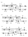
この発明の基板搬送装置11は上記のような構成であり、液晶パネルの各製造工程や装置内でのガラス基板の搬送に用いるものであり、図5と図6は、複数台の装置11を連結使用して基板Aを搬送する状態を示し、各基板搬送装置11は、モータ24の起動により、両側のエンドレス走行体16が、上部走行部分が後部から前部に向かって図5(b)の時計方向に等速で回動し、基板搬送装置11上に供給された基板Aは、エンドレス走行体16の上部走行部分間の前後の載置部材固定軸17に設けた複数の基板載置部材18によって水平に支持され、基板Aの載った載置部材固定軸17は図5(b)の左から右側に向けて水平移動して基板Aを搬送する。
The
基板載置部材18は、載置部材固定軸17の軸方向に複数が点在的に設けられ、基板Aと基板載置部材18の接触部分を極端に少なくすることができ、また、基板載置部材18は移動時に回転することがないので、基板載置部材18と基板Aは擦れることがなく、異物の発生をなくすことができる。
A plurality of
また、両側のエンドレス走行体16とガイドローラ30が転動するレール28、29の部分がカバー31によって覆われ、このカバー31内が吸引アダプタ33と接続された適宜な吸引手段(図示しない)によって吸引されているので、エンドレス走行体16とガイドローラ30及びレール28と29の部分で異物が発生したとしても、この異物を吸引アダプタ33を通じて吸引手段で吸引することにより、基板Aを搬送する部分への異物の拡散はなく、従って、異物が基板Aに付着するのを有効に防止することができる。
Further, the portions of the
図6は、前後の基板搬送装置11間における基板Aの受け渡し状態を示し、図6(a)のように、後位基板搬送装置11で搬送される基板Aが前位基板搬送装置11上に送り出される時、最前部に達した基板載置部材18は下方に移行するので、この基板載置部材18による支持が解かれた基板Aの先端部は、同図二点鎖線で示すように、先端部が下方に垂れ下がり状となって前位基板搬送装置11上に進入する。
FIG. 6 shows a delivery state of the substrate A between the front and rear
図6(b)のように、前位基板搬送装置11の後端側に戻った基板載置部材18は、下方から上方に回動しながら移動するので、この基板載置部材18が下面側からすくい上げるように基板Aの先端部を受け取ることになり、基板Aと基板載置部材18の衝突の発生がなく、基板Aの先端部が垂れ下がっていても、図6(c)のように、垂れ下がりに何ら関係なく基板Aを円滑に受け取ることができ、この前位基板搬送装置11で更に基板Aを前方に搬送することになる。
As shown in FIG. 6B, the
なお、この発明の基板搬送装置の各構成部材は以上述べた実施例のものに限定されるものではなく、この発明の目的の範囲内で適宜設計変更して実施することができる。 The constituent members of the substrate transfer apparatus of the present invention are not limited to those of the above-described embodiments, and can be implemented with appropriate design changes within the scope of the object of the present invention.
しかし、エンドレス走行体16についてはチェーンとするのでは駆動時に振動が生じることが考えられるので、実施例のようなエンドレスベルト状とするのが好ましい。
However, if the endless traveling
1 カレット洗浄装置
2 洗浄ユニット
3 偏光板貼り付け装置
4 貼り付けテーブル
5 偏光板貼り付けユニット
6 ローラ
7 駆動ローラ
8 従動ローラ
9 搬送ベルト
10 支持板
11 基板搬送装置
12 棧
13 横棧
14 前棧
15 後棧
16 エンドレス走行体
17 載置部材固定軸
18 基板載置部材
19 支持壁
20 駆動軸
21 従動軸
22 駆動プーリ
23 従動プーリ
24 モータ
25 プーリ
26 駆動ベルト
27 連結部材
28 上レール
29 下レール
30 ガイドローラ
31 カバー
32 長孔
33 吸引アダプタ
34 駆動ユニット
A 基板
A1 大型基板
A2 小型基板
DESCRIPTION OF SYMBOLS 1 Caret washing | cleaning
Claims (3)
Priority Applications (1)
| Application Number | Priority Date | Filing Date | Title |
|---|---|---|---|
| JP2004002798A JP2005194060A (en) | 2004-01-08 | 2004-01-08 | Substrate transport device |
Applications Claiming Priority (1)
| Application Number | Priority Date | Filing Date | Title |
|---|---|---|---|
| JP2004002798A JP2005194060A (en) | 2004-01-08 | 2004-01-08 | Substrate transport device |
Publications (2)
| Publication Number | Publication Date |
|---|---|
| JP2005194060A true JP2005194060A (en) | 2005-07-21 |
| JP2005194060A5 JP2005194060A5 (en) | 2007-01-25 |
Family
ID=34817884
Family Applications (1)
| Application Number | Title | Priority Date | Filing Date |
|---|---|---|---|
| JP2004002798A Pending JP2005194060A (en) | 2004-01-08 | 2004-01-08 | Substrate transport device |
Country Status (1)
| Country | Link |
|---|---|
| JP (1) | JP2005194060A (en) |
Cited By (5)
| Publication number | Priority date | Publication date | Assignee | Title |
|---|---|---|---|---|
| JP2007152251A (en) * | 2005-12-06 | 2007-06-21 | Dainippon Screen Mfg Co Ltd | Coating apparatus |
| KR100850122B1 (en) * | 2006-05-08 | 2008-08-04 | 엔이씨 엘씨디 테크놀로지스, 엘티디. | Panel washing machine and washing method |
| JP2009295806A (en) * | 2008-06-05 | 2009-12-17 | Sekisui Chem Co Ltd | Surface processing apparatus |
| KR101204089B1 (en) * | 2007-12-24 | 2012-11-22 | 삼성테크윈 주식회사 | Roll-to-roll substrate transfer apparatus, wet etching apparatus comprising the same and apparatus for manufacturing printed circuit board |
| JP2015101522A (en) * | 2013-11-27 | 2015-06-04 | 旭硝子株式会社 | Cutting device for glass plate, cutting method for glass plate, and manufacturing method for glass plate |
-
2004
- 2004-01-08 JP JP2004002798A patent/JP2005194060A/en active Pending
Cited By (9)
| Publication number | Priority date | Publication date | Assignee | Title |
|---|---|---|---|---|
| JP2007152251A (en) * | 2005-12-06 | 2007-06-21 | Dainippon Screen Mfg Co Ltd | Coating apparatus |
| JP4544470B2 (en) * | 2005-12-06 | 2010-09-15 | 大日本スクリーン製造株式会社 | Coating device |
| KR100850122B1 (en) * | 2006-05-08 | 2008-08-04 | 엔이씨 엘씨디 테크놀로지스, 엘티디. | Panel washing machine and washing method |
| KR101204089B1 (en) * | 2007-12-24 | 2012-11-22 | 삼성테크윈 주식회사 | Roll-to-roll substrate transfer apparatus, wet etching apparatus comprising the same and apparatus for manufacturing printed circuit board |
| JP2009295806A (en) * | 2008-06-05 | 2009-12-17 | Sekisui Chem Co Ltd | Surface processing apparatus |
| JP2015101522A (en) * | 2013-11-27 | 2015-06-04 | 旭硝子株式会社 | Cutting device for glass plate, cutting method for glass plate, and manufacturing method for glass plate |
| KR20150061601A (en) * | 2013-11-27 | 2015-06-04 | 아사히 가라스 가부시키가이샤 | Cutting device of glass sheet, cutting method of glass sheet and producing method of glass sheet |
| TWI624438B (en) * | 2013-11-27 | 2018-05-21 | Asahi Glass Co Ltd | Glass plate cutting device, glass plate cutting method, and glass plate manufacturing method |
| KR102237439B1 (en) | 2013-11-27 | 2021-04-07 | 에이지씨 가부시키가이샤 | Cutting device of glass sheet, cutting method of glass sheet and producing method of glass sheet |
Similar Documents
| Publication | Publication Date | Title |
|---|---|---|
| JP2010207687A (en) | Substrate conveying apparatus | |
| JP2009000631A (en) | Dust removal apparatus | |
| TWI393205B (en) | Substrate transmission apparatus and substrate transmission method | |
| JP2007301427A (en) | Panel cleaner and method for cleaning panel | |
| TWI272236B (en) | Conveyor of sheet body | |
| JP2013049004A (en) | Dust removal device | |
| CN209792056U (en) | Glass substrate's belt cleaning device | |
| JP2005194060A (en) | Substrate transport device | |
| JP2011121781A (en) | Conveyor belt, and conveying device and disruption system provided with the same | |
| JP2007184391A (en) | Method and apparatus of conveying substrate | |
| JPH07283185A (en) | Substrate cleaner | |
| JP4602567B2 (en) | Substrate cleaning device | |
| JP2010060253A (en) | Device for removing liquid attached to glass plate and method of removing liquid attached to glass plate | |
| JP2000254605A (en) | Cleaning device for flexible substrate | |
| JP6370578B2 (en) | Substrate cleaning device | |
| JP2006003036A (en) | Drying device | |
| CN212168839U (en) | Pin cutting machine for circuit board | |
| JP4908316B2 (en) | Cleaning apparatus, flat panel display manufacturing apparatus and flat panel display | |
| JP3388988B2 (en) | Substrate processing equipment | |
| JP2005152717A (en) | Dust removing apparatus | |
| JP2014185029A (en) | Recording device | |
| KR200495902Y1 (en) | Substrate cleaning apparatus | |
| JPH07241534A (en) | Substrate cleaning apparatus | |
| CN210654802U (en) | PCB conveying device with cleaning function | |
| WO2011148548A1 (en) | Apparatus for transferring flat board |
Legal Events
| Date | Code | Title | Description |
|---|---|---|---|
| A521 | Written amendment |
Free format text: JAPANESE INTERMEDIATE CODE: A821 Effective date: 20060715 |
|
| RD02 | Notification of acceptance of power of attorney |
Free format text: JAPANESE INTERMEDIATE CODE: A7422 Effective date: 20060715 |
|
| A521 | Written amendment |
Effective date: 20061127 Free format text: JAPANESE INTERMEDIATE CODE: A523 Effective date: 20061127 Free format text: JAPANESE INTERMEDIATE CODE: A821 |
|
| A621 | Written request for application examination |
Free format text: JAPANESE INTERMEDIATE CODE: A621 Effective date: 20061127 |
|
| A977 | Report on retrieval |
Free format text: JAPANESE INTERMEDIATE CODE: A971007 Effective date: 20090423 |
|
| A131 | Notification of reasons for refusal |
Effective date: 20090428 Free format text: JAPANESE INTERMEDIATE CODE: A131 |
|
| A02 | Decision of refusal |
Free format text: JAPANESE INTERMEDIATE CODE: A02 Effective date: 20090908 |