JP2005181663A - Method for correcting mask pattern - Google Patents
Method for correcting mask pattern Download PDFInfo
- Publication number
- JP2005181663A JP2005181663A JP2003422158A JP2003422158A JP2005181663A JP 2005181663 A JP2005181663 A JP 2005181663A JP 2003422158 A JP2003422158 A JP 2003422158A JP 2003422158 A JP2003422158 A JP 2003422158A JP 2005181663 A JP2005181663 A JP 2005181663A
- Authority
- JP
- Japan
- Prior art keywords
- edge
- pattern
- correction
- mask pattern
- light intensity
- Prior art date
- Legal status (The legal status is an assumption and is not a legal conclusion. Google has not performed a legal analysis and makes no representation as to the accuracy of the status listed.)
- Pending
Links
- 238000000034 method Methods 0.000 title claims abstract description 52
- 238000012937 correction Methods 0.000 claims abstract description 139
- 238000002955 isolation Methods 0.000 claims abstract description 39
- 238000013461 design Methods 0.000 claims description 44
- 238000013459 approach Methods 0.000 claims description 10
- 230000000694 effects Effects 0.000 claims description 7
- 238000000206 photolithography Methods 0.000 claims description 5
- 230000007423 decrease Effects 0.000 abstract 1
- 230000003247 decreasing effect Effects 0.000 abstract 1
- 230000010363 phase shift Effects 0.000 description 12
- 230000003287 optical effect Effects 0.000 description 9
- 238000012545 processing Methods 0.000 description 7
- 238000000059 patterning Methods 0.000 description 6
- 238000004088 simulation Methods 0.000 description 3
- 230000008021 deposition Effects 0.000 description 2
- 238000011156 evaluation Methods 0.000 description 2
- 238000001459 lithography Methods 0.000 description 2
- 238000012804 iterative process Methods 0.000 description 1
- 239000004065 semiconductor Substances 0.000 description 1
- 238000012546 transfer Methods 0.000 description 1
Images

Classifications
-
- G—PHYSICS
- G03—PHOTOGRAPHY; CINEMATOGRAPHY; ANALOGOUS TECHNIQUES USING WAVES OTHER THAN OPTICAL WAVES; ELECTROGRAPHY; HOLOGRAPHY
- G03F—PHOTOMECHANICAL PRODUCTION OF TEXTURED OR PATTERNED SURFACES, e.g. FOR PRINTING, FOR PROCESSING OF SEMICONDUCTOR DEVICES; MATERIALS THEREFOR; ORIGINALS THEREFOR; APPARATUS SPECIALLY ADAPTED THEREFOR
- G03F1/00—Originals for photomechanical production of textured or patterned surfaces, e.g., masks, photo-masks, reticles; Mask blanks or pellicles therefor; Containers specially adapted therefor; Preparation thereof
- G03F1/36—Masks having proximity correction features; Preparation thereof, e.g. optical proximity correction [OPC] design processes
Landscapes
- Physics & Mathematics (AREA)
- General Physics & Mathematics (AREA)
- Exposure And Positioning Against Photoresist Photosensitive Materials (AREA)
- Preparing Plates And Mask In Photomechanical Process (AREA)
Abstract
Description
本発明は、マスクパターンを用いた光リソグラフィにより、設計パターンに対応した所望のレジストパターンを得るために、前記マスクパターンの補正を行う方法に関するものである。 The present invention relates to a method for correcting a mask pattern in order to obtain a desired resist pattern corresponding to a design pattern by photolithography using the mask pattern.
半導体装置を形成するためにリソグラフィ工程がある。
リソグラフィ工程は、レジストに投影光学系の露光機を用いてパターニングを施す処理であり、このパターニングを施すために露光機には、レチクルと称されるマスクパターンを備えており、該マスクパターンに光を照射して透過した像でレジストにパターニングを施す。
ところで、前記したマスクパターンを用いた露光機でパターニングを行うとき、当該露光機の解像度の限界性能に近いと、設計パターンの形状と異なったパターン形状になってしまう。
There is a lithography process to form a semiconductor device.
The lithography process is a process for patterning a resist using an exposure machine of a projection optical system. In order to perform this patterning, the exposure machine is provided with a mask pattern called a reticle. The resist is patterned with an image transmitted through irradiation.
By the way, when patterning is performed with an exposure machine using the mask pattern described above, a pattern shape different from the shape of the design pattern is obtained if the resolution is close to the limit performance of the exposure machine.
これを解決するためにマスクパターンに補正を施して、設計パターンのパターン形状に近づける、いわゆる光近接効果補正(Optical Proximity Correction)が行なわれている。
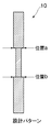
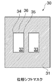
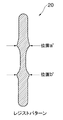
この光近接効果補正を位相シフトマスクによる2回露光の例で説明する。設計されたパターン10が図2に示されており、該パターンをマスクパターンとしてレジストにパターニングを行なうための位相シフトマスクが図3にCrトリムマスクが図4に示されており、これらのマスクの重ね合わせ露光でレジストにパターニングを行なったときのレジストパターン20が図5に示されている。
In order to solve this, so-called optical proximity correction (Optical Proximity Correction) is performed in which a mask pattern is corrected to approach the pattern shape of a design pattern.
This optical proximity correction will be described using an example of twice exposure using a phase shift mask. The designed
設計パターン10は、1つの矩形と、該矩形の各両端に前記矩形より横幅寸法が大きな矩形がそれぞれ接した形状である。このような形状で単にパターニングを行なったときのレジストパターンは、図5に示すように、矩形の角が面取りされ、図2の位置aおよび位置bに対応する図5の位置a’および位置b’の横幅寸法は位置aおよび位置bの横幅寸法より大きく形成されてしまう。
The
ところで、前記した位相シフトマスク30は、Cr遮光部分31と、0度の位相シフター32と、180度の位相シフター33とを有しており、Cr遮光部分31に0度位相シフター32および180度位相シフター33が含まれている。図3に示す位相シフトマスク30において、頂点34および頂点35間で規定される線をエッジ35と称し、このエッジは位相シフトマスク30以外に設計パターン10やレジストパターン20などの規定可能の線を示す。
The
光近接効果法は、予め図3の位相シフトマスク30のエッジや図4のCrトリムマスク40のエッジに補正を施し、露光により転写されるパターンを設計パターン10に近づける手法である。すなわち、図5の位置a’および位置b’は、横幅寸法が大きく形成されてしまうことから、位置a’および位置b’の横幅寸法が大きく形成されないように、該位置a’および位置b’に対応している設計パターン10の位置aおよび位置bに対応している位相シフトマスク30やCrトリムマスク40などのマスクパターンのエッジ形状に対し補正を施す。
The optical proximity effect method is a method in which the edge of the
ところで、前記した光近接効果補正によるマスクパターンの修正方法が、特許文献1〜特許文献3に示されている。 By the way, a method of correcting a mask pattern by the above-described optical proximity effect correction is disclosed in Patent Documents 1 to 3.
特許文献1によれば、光近接効果補正を行うべく、マスクパターンをモデル化して、光強度分布をシミュレーションして当該マスクパターンに補正を施す方法が開示されている。
また、特許文献2によれば、マスクパターンを分類化して、分類したマスクパターンに光近接効果補正を施す方法が開示されている。
更に、特許文献3によれば、マスクパターンの外周に沿って評価点を付して、該評価点に基づいてマスクパターンを補正する方法が開示されている。
ところで、前記した補正方法では、所望のマスクパターンを得るために、該マスクパターン上に照射される光の堆積エネルギーの強度分布を2次元光強度分布として求め、この2次元光強度分布に基づくシミュレーションを繰返すことでマスクパターンの補正を行っている。
Patent Document 2 discloses a method of classifying mask patterns and performing optical proximity effect correction on the classified mask patterns.
Further, Patent Document 3 discloses a method of attaching an evaluation point along the outer periphery of the mask pattern and correcting the mask pattern based on the evaluation point.
By the way, in the correction method described above, in order to obtain a desired mask pattern, the intensity distribution of the deposition energy of light irradiated on the mask pattern is obtained as a two-dimensional light intensity distribution, and a simulation based on the two-dimensional light intensity distribution is performed. The mask pattern is corrected by repeating the above.
ところが、2次元光強度分布は堆積エネルギーの強度分布をマスクパターン全域において求める必要があることから、該2次元光強度分布を算出する処理が多いと、マスクパターンの修正に時間を要してしまい、作業効率が低減してしまう。
従って、本発明の目的は、作業効率の低下を招くことなく、所望のマスクパターンを得る方法を提供することにある。
However, since the two-dimensional light intensity distribution needs to obtain the intensity distribution of the deposition energy over the entire mask pattern, if there are many processes for calculating the two-dimensional light intensity distribution, it takes time to correct the mask pattern. , Work efficiency will be reduced.
Therefore, an object of the present invention is to provide a method for obtaining a desired mask pattern without causing a reduction in work efficiency.
本発明は、以上の点を解決するために、次の構成を採用する。
〈構成1〉
設計パターンに対応したマスクパターンを光リソグラフィで得るために、前記マスクパターンの補正を行う方法において、前記マスクパターン全域の2次元光強度分布に基づいて、前記マスクパターンにおけるパターンエッジを規定する補正前パターンエッジ規定工程と、規定したパターンエッジと、前記設計パターンのパターンエッジとの乖離値が小さい設計パターン上の位置を接近点、乖離値が大きい設計パターン上の位置を隔絶点として設定する乖離位置設定工程と、前記隔絶点から所定の範囲内にある前記マスクパターン側の各エッジに対し、微小量補正を施し、前記近接点に対応する前記マスクパターン側の位置での光強度と前記隔絶点に対応する前記マスクパターン側の位置での光強度との変化量を求め、近接点光強度の変化量が小さくなり、かつ隔絶点光強度の変化量が大きくなる補正対象エッジを前記マスクパターン側の前記各エッジから選定するエッジ選定工程と、選定した前記補正対象エッジに対し、補正後の前記隔絶点光強度が所定の補正基準を満たすべく、前記補正対象エッジに補正を施すことを繰返す補正工程と、前記補正対象エッジに補正を施したマスクパターン全域の2次元光強度分布に基づいて、改めて補正パターンエッジを規定する補正後パターンエッジ規定工程と、改めて規定した補正パターンエッジと設計パターンのエッジとの乖離が所定の補正終了判定基準内であるとき、前記マスクパターンの補正を終了する終了判定工程とで構成されることを特徴とする。
The present invention adopts the following configuration in order to solve the above points.
<Configuration 1>
In the method of correcting the mask pattern in order to obtain a mask pattern corresponding to the design pattern by photolithography, before the correction for defining the pattern edge in the mask pattern based on the two-dimensional light intensity distribution of the entire mask pattern. Deviation position for setting a position on the design pattern having a small deviation value between the pattern edge defining step, the defined pattern edge, and the pattern edge of the design pattern as an approach point and a position on the design pattern having a large deviation value as an isolation point A setting step, applying a minute amount correction to each edge on the mask pattern side within a predetermined range from the isolation point, and the light intensity at the position on the mask pattern side corresponding to the proximity point and the isolation point The amount of change with the light intensity at the position on the mask pattern side corresponding to An edge selection step for selecting a correction target edge from the respective edges on the mask pattern side, which is small and increases the amount of change in the isolation point light intensity, and the isolated point light after correction with respect to the selected correction target edge Based on a correction process for repeatedly performing correction on the correction target edge so that the intensity satisfies a predetermined correction criterion, and a two-dimensional light intensity distribution in the entire mask pattern on which the correction target edge has been corrected A post-correction pattern edge defining step for defining an edge, and an end determining step for ending correction of the mask pattern when a deviation between the newly defined correction pattern edge and the design pattern edge is within a predetermined correction end determination criterion; It is characterized by comprising.
〈構成2〉
設計パターンに対応したマスクパターンを光リソグラフィで得るために、前記マスクパターンの補正を行う方法において、前記マスクパターン全域の2次元光強度分布に基づいて、前記マスクパターンにおけるパターンエッジを規定する補正前パターンエッジ規定工程と、規定したパターンエッジと、前記設計パターンのパターンエッジとの乖離値が小さい設計パターン上の位置を接近点、乖離値が大きい設計パターン上の位置を隔絶点として設定する乖離位置設定工程と、前記隔絶点から所定の範囲内にある前記マスクパターン側の各エッジに対し、微小量補正を施し、前記近接点に対応する前記マスクパターン側の位置での光強度と前記隔絶点に対応する前記マスクパターン側の位置での光強度との変化量を求め、近接点光強度の変化量が小さくなり、かつ隔絶点光強度の変化量が大きくなる補正対象エッジを前記マスクパターン側の前記各エッジから選定するエッジ選定工程と、選定した前記補正対象エッジに補正を施し、補正後のマスクパターンの前記近接点光強度および前記隔絶点光強度を求め、前記近接点光強度が所定の選定判断基準値より外れているとき、改めてエッジ選定工程を行ない、前記選定判断基準値内であるときには補正後の前記隔絶点光強度が所定の補正基準を満たすべく、前記補正対象エッジに補正を施すことを繰返す補正工程と、前記補正対象エッジに補正を施したマスクパターンの全域の2次元光強度分布に基づいて、改めて補正パターンエッジを規定する補正後パターンエッジ規定工程と、改めて規定した補正パターンエッジと設計パターンのエッジとの乖離が所定の補正終了判定基準内であるとき、前記マスクパターンの補正を終了する終了判定工程とで構成されることを特徴とする。
<Configuration 2>
In the method of correcting the mask pattern in order to obtain a mask pattern corresponding to the design pattern by photolithography, before the correction for defining the pattern edge in the mask pattern based on the two-dimensional light intensity distribution of the entire mask pattern. Deviation position for setting a position on the design pattern having a small deviation value between the pattern edge defining step, the defined pattern edge, and the pattern edge of the design pattern as an approach point and a position on the design pattern having a large deviation value as an isolation point A setting step, applying a minute amount correction to each edge on the mask pattern side within a predetermined range from the isolation point, and the light intensity at the position on the mask pattern side corresponding to the proximity point and the isolation point The amount of change with the light intensity at the position on the mask pattern side corresponding to An edge selection step for selecting a correction target edge from the respective edges on the mask pattern side, which is reduced and the change amount of the isolation point light intensity is increased, and the selected mask to be corrected is corrected, and the corrected mask pattern The near point light intensity and the isolation point light intensity of the light source are determined, and when the near point light intensity is out of a predetermined selection criterion value, an edge selection step is performed again, and when it is within the selection criterion value, the correction is performed. A correction step of repeatedly performing correction on the correction target edge so that the later isolated point light intensity satisfies a predetermined correction criterion; and a two-dimensional light intensity distribution over the entire mask pattern in which the correction target edge is corrected The corrected pattern edge defining step for redefining the correction pattern edge based on the When Tsu discrepancy between di is within a predetermined correction termination criterion, characterized in that it is constituted by the end determining step of terminating the correction of the mask pattern.
〈構成3〉
前記エッジ選定工程は、前記隔絶点から近接効果補正の及ぶ範囲内にある前記マスクパターン側の各エッジから選定することを特徴とする。
<Configuration 3>
The edge selection step is characterized in that selection is made from each edge on the mask pattern side within a range covered by proximity effect correction from the isolation point.
本発明のマスクパターンの修正方法は、規定したパターンエッジと前記設計パターンのパターンエッジとの接近点と隔絶点とを求め、該隔絶点から所定の範囲内にある前記マスクパターン側の各エッジに対し微小量補正を施し、該マスクパターン側の前記接近点の位置での光強度の変化量が小さくなり、かつ前記隔絶点の位置での光強度の変化量が大きくなる補正対象エッジを選定し、選定した補正対象エッジに対し補正後の前記隔絶点光強度が所定の補正基準を満たすように補正を施すことを繰返し、補正後のマスクパターンに基づいて改めて規定した補正パターンエッジと設計パターンのエッジとが所定の補正終了判定基準を満たすとき、前記マスクパターンの補正を終了することにより、補正が不必要なパターンの光強度の影響を抑え、かつ設計パターンのパターンエッジとマスクパターンのパターンエッジとの誤差が大きなパターンエッジを選択して補正を行うことから、マスクパターン全域の2次元光強度分布を頻繁に求める必要がなく、処理時間を短縮することができ、作業効率を向上させることができる。 According to the mask pattern correcting method of the present invention, an approach point and an isolation point between a specified pattern edge and the pattern edge of the design pattern are obtained, and each mask pattern side edge within a predetermined range from the isolation point is obtained. The correction target edge is selected so that the amount of change in light intensity at the position of the approach point on the mask pattern side is small and the amount of change in light intensity at the position of the isolation point is large. , Repeatedly correcting the selected correction target edge so that the isolated point light intensity after correction satisfies a predetermined correction standard, and the correction pattern edge and design pattern defined again based on the corrected mask pattern When the edge meets a predetermined correction end criterion, the correction of the mask pattern is terminated to suppress the influence of the light intensity of the pattern that does not need to be corrected. In addition, since the pattern edge with a large error between the pattern edge of the design pattern and the pattern edge of the mask pattern is selected and corrected, it is not necessary to frequently obtain the two-dimensional light intensity distribution in the entire mask pattern, and the processing time is shortened. Work efficiency can be improved.
以下、本発明の実施形態を図を用いて詳細に説明する。 Hereinafter, embodiments of the present invention will be described in detail with reference to the drawings.
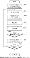
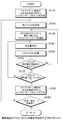
本発明のマスクパターンの修正方法は、図2に示す設計パターンをレジストに転写するために図3に示す位相シフトマスクおよび図4に示すCrトリムマスクなどのマスクパターンを用いてパターニングを施し、レジストに転写されたレジストパターン(図5に示す)が設計パターンに近似するように、マスクパターンに予め補正を施す方法であり、すなわち補正前パターンエッジ規定工程と、乖離位置設定工程と、エッジ選択工程と、補正工程と、パターンエッジ規定工程と、終了判定工程とで構成されている。これらの各工程を図1のフローチャートに沿って説明する。 In order to transfer the design pattern shown in FIG. 2 to the resist, the mask pattern correcting method of the present invention is patterned using a mask pattern such as the phase shift mask shown in FIG. 3 and the Cr trim mask shown in FIG. In this method, the mask pattern is corrected in advance so that the resist pattern (shown in FIG. 5) transferred to the pattern approximates the design pattern. That is, the pre-correction pattern edge defining step, the deviation position setting step, and the edge selection step And a correction step, a pattern edge defining step, and an end determination step. Each of these steps will be described with reference to the flowchart of FIG.
補正前パターンエッジ規定工程は、先ず補正すべきマスクパターンを用いたシミュレーションを行ない、このシミュレーションにおけるレジストパターン全域の2次元光強度分布を補正前のマスクパターン全域の2次元光強度分布として求め、次に求めた2次元光強度の値と所定の閾値とを比較して当該マスクパターンにおける補正前のパターンエッジを規定する(ステップS10)。 In the pre-correction pattern edge defining step, first, a simulation using the mask pattern to be corrected is performed, and the two-dimensional light intensity distribution in the entire resist pattern in this simulation is obtained as the two-dimensional light intensity distribution in the entire mask pattern before correction. The two-dimensional light intensity value obtained in step 1 is compared with a predetermined threshold value to define a pattern edge before correction in the mask pattern (step S10).
次に、補正前パターンエッジ規定工程で求めたパターンエッジと設計パターンのパターンエッジとの乖離値を求める。つまり乖離位置設定工程では、図2の設計パターンにおける位置aに対応する補正前パターンエッジの位置を求め、求めた位置と設計パターンの位置aとの乖離値を求める。このようにして求めた乖離値に基づいて、乖離値が最も低い設計パターン上の位置を接近点P1、反対に乖離値が最も高い設計パターン上の位置を隔絶点P2として設定する(ステップS20)。
このとき、隔絶点P2が複数あるとき、先ず複数の隔絶点から任意の1点を選定する。また接近点P1が複数あるとき、隔絶点P2に最も近い接近点P1を選定する。
Next, a deviation value between the pattern edge obtained in the pre-correction pattern edge defining step and the pattern edge of the design pattern is obtained. That is, in the deviation position setting step, the position of the pattern edge before correction corresponding to the position a in the design pattern of FIG. 2 is obtained, and the deviation value between the obtained position and the position a of the design pattern is obtained. Based on the deviation value thus obtained, the position on the design pattern having the lowest deviation value is set as the approach point P1, and the position on the design pattern having the highest deviation value is set as the isolation point P2 (step S20). .
At this time, when there are a plurality of isolated points P2, an arbitrary one point is first selected from the plurality of isolated points. Further, when there are a plurality of approach points P1, the approach point P1 closest to the isolation point P2 is selected.
その後エッジ選定工程では、例えば図3に示す位相シフトマスク30において、頂点34および頂点35間で規定される線をエッジ36と称し、このように規定されるエッジにおいて、特に隔絶点P2近傍の複数のエッジから、補正対象のエッジを選定する(ステップS30)。
ここで、エッジ選定工程を具体的に説明する。
隔絶点P2から所定の距離離れた範囲にあるマスクパターンのエッジMn(n=1、2、・・・)の各々について、マスクパターンのエッジを微小量dMnだけ動かしたときの、近接点P1における光強度の変化量dI(P1)/dMnと、隔絶点P2における光強度の変化量dI(P2)/dMnとを求め、dI(P1)/dMnが0乃至最小となり、かつdI(P2)/dMnが最大となるマスクパターンのエッジMnを、補正対象エッジとして選択する。
Thereafter, in the edge selection step, for example, in the
Here, the edge selection process will be specifically described.
For each edge Mn (n = 1, 2,...) Of the mask pattern within a predetermined distance from the isolation point P2, the edge of the mask pattern is moved by a minute amount dMn at the proximity point P1. The light intensity change amount dI (P1) / dMn and the light intensity change amount dI (P2) / dMn at the isolation point P2 are obtained, and dI (P1) / dMn is 0 to minimum, and dI (P2) / The edge Mn of the mask pattern that maximizes dMn is selected as the correction target edge.
補正対象エッジは、近接点P1と隔絶点P2との2点の光強度を求め、その変化量に基づいて選択を行うことにより、マスクパターン全域、すなわちマスクパターン全域における各点での2次元光強度を求める必要がないことから、処理時間を短縮することができる。
また隔絶点P2における変化量が大きく、かつ近接点P1における変化量が少ないエッジを補正対象として選択することにより、設計パターンとの乖離値が大きなエッジに対し補正を施すことができ、かつ設計パターンとの乖離値が小さい近接点では、その補正の影響のおよぶ恐れを抑えることができる。
ところで、前記所定の距離は例えば光近接効果補正が及ぶ範囲の距離として露光波長の2倍を適用する。また、この所定の距離は露光波長の2倍に限る必要はなく、適宜変更してもよい。
The correction target edge is obtained by calculating the light intensity of two points, the proximity point P1 and the isolation point P2, and performing selection based on the amount of change, whereby two-dimensional light at each point in the mask pattern region. Since it is not necessary to obtain the strength, the processing time can be shortened.
Further, by selecting an edge having a large change amount at the isolation point P2 and a small change amount at the close point P1 as a correction target, an edge having a large deviation value from the design pattern can be corrected and the design pattern can be corrected. At a proximity point with a small deviation value, the possibility of the influence of the correction can be suppressed.
By the way, as the predetermined distance, for example, twice the exposure wavelength is applied as a distance within a range that the optical proximity effect correction can reach. The predetermined distance is not limited to twice the exposure wavelength, and may be changed as appropriate.
次の補正工程がステップS40〜ステップS60に示されている。
先ず、選択したマスクパターンのエッジに対し補正を施す(ステップS40)。例えば、図3のマスクパターンとしての位相シフトマスクのエッジ36の補正は、0度位相シフター31の矩形形状の縦方向に伸張させるか若しくは収縮させるべく、微小量の補正を施す。
このようにして補正が施されたマスクパターンにおける前記隔絶点P2の位置での光強度I(P2)を求める(ステップS50)。
求めた隔絶点光強度I(P2)と、所定の補正基準値との比較を行ない、求めた光強度I(P2)が前記補正基準値に達しているか否かを判定する(ステップS60)。この判定で、所定の補正基準値を満たしていないと判断すると、ステップ40からの処理に戻って、選択したマスクパターンに対し改めて補正を施す。
The next correction process is shown in steps S40 to S60.
First, the edge of the selected mask pattern is corrected (step S40). For example, in the correction of the
The light intensity I (P2) at the position of the isolation point P2 in the mask pattern thus corrected is obtained (step S50).
The obtained isolated point light intensity I (P2) is compared with a predetermined correction reference value to determine whether or not the obtained light intensity I (P2) has reached the correction reference value (step S60). If it is determined in this determination that the predetermined correction reference value is not satisfied, the process returns to step 40, and the selected mask pattern is corrected again.
所定の補正基準値を満たしていると判断されると、補正後パターンエッジ規定工程を行う。すなわち補正後のマスクパターン全域の2次元光強度分布を求め、所定の閾値との比較を行ない当該マスクパターンにおける補正後のパターンエッジを規定する(ステップS70)。 If it is determined that the predetermined correction reference value is satisfied, a post-correction pattern edge defining step is performed. That is, a two-dimensional light intensity distribution in the entire mask pattern after correction is obtained and compared with a predetermined threshold value to define a corrected pattern edge in the mask pattern (step S70).
補正後にパターンエッジを規定した後、終了判定工程では、規定したパターンエッジと設計パターンのエッジとの乖離値を求め、その乖離値に基づいて所定の補正終了判定基準を満たすか否かを判定する(ステップS80)。この判定で補正終了判定基準を満たさないとき、前記したステップS30からのエッジ選定工程を行う。
一方、補正後に規定したパターンエッジと設計パターンのエッジとの乖離が所定の補正終了判定基準を満たしていると判断したとき、マスクパターンの補正を終了する。
After defining the pattern edge after correction, in the end determination step, a deviation value between the specified pattern edge and the edge of the design pattern is obtained, and it is determined whether or not a predetermined correction end determination criterion is satisfied based on the deviation value. (Step S80). When this determination does not satisfy the correction end determination criterion, the edge selection process from step S30 described above is performed.
On the other hand, when it is determined that the deviation between the pattern edge defined after the correction and the edge of the design pattern satisfies a predetermined correction end determination criterion, the correction of the mask pattern is ended.
前記したように実施例1のマスクパターンの修正方法によれば、補正すべきマスクパターンと設計パターンとの乖離を示す近接点および隔絶点との光強度分布に基づいてパターンエッジを選択し、その補正対象エッジに対し、隔絶点における光強度が所定の補正基準を満たすべく補正を施すことにより、補正のためにマスクパターン全域の2次元光強度分布を求めることを頻繁に繰り返す必要がないことから、マスクパターンの補正処理に要する時間を低減することができる。 As described above, according to the mask pattern correction method of the first embodiment, the pattern edge is selected based on the light intensity distribution between the proximity point and the isolation point indicating the deviation between the mask pattern to be corrected and the design pattern, By correcting the edge to be corrected so that the light intensity at the isolation point satisfies a predetermined correction criterion, it is not necessary to repeatedly determine the two-dimensional light intensity distribution over the entire mask pattern for correction. The time required for the mask pattern correction process can be reduced.
次に、マスクパターンの補正中に光強度に基づく判定を行ない、改めて補正対象エッジを選定する新たな補正工程が特徴のマスクパターンの修正方法を図6のフローチャートに沿って説明する。
実施例2のマスクパターンの修正方法は、補正前パターンエッジ工程と、乖離位置設定工程と、エッジ選定工程と、補正工程と、補正後パターン規定工程と、終了判定工程とで構成されている。
Next, a mask pattern correction method characterized by a new correction step in which a determination based on light intensity is performed during mask pattern correction and a correction target edge is newly selected will be described with reference to the flowchart of FIG.
The mask pattern correction method according to the second embodiment includes a pre-correction pattern edge process, a deviation position setting process, an edge selection process, a correction process, a post-correction pattern defining process, and an end determination process.
補正前パターンエッジ工程、乖離位置設定工程、エッジ選定工程、補正後パターン規定工程および終了判定工程の内容は、前記した実施例1と同様であり、図6のフローチャートにおいて、補正前パターンエッジ工程がステップS110、乖離位置設定工程がステップS120、エッジ選定工程がステップS130、補正後パターン規定工程がステップS180および終了判定工程がステップS190に対応している。
尚、実施例1と同様である工程内容の説明は割愛し、本実施例の補正工程の内容をステップS140〜ステップS170に沿って詳細に説明する。
The contents of the pre-correction pattern edge process, the divergence position setting process, the edge selection process, the post-correction pattern defining process, and the end determination process are the same as those in the first embodiment. In the flowchart of FIG. Step S110, the deviation position setting step corresponds to step S120, the edge selection step corresponds to step S130, the corrected pattern defining step corresponds to step S180, and the end determination step corresponds to step S190.
In addition, description of the process content similar to Example 1 is omitted, and the content of the correction process of a present Example is demonstrated in detail along step S140-step S170.
ステップ130におけるエッジ選定工程で、補正すべきマスクパターンのエッジを選定した後、選択したエッジに対し前記した実施例1と同様に補正を施す(ステップS140)。
次に、選択したエッジに対し補正を施したマスクパターンにおける近接点P1の位置での光強度I(P1)と、隔絶点P2の位置での光強度I(P2)とを求める(ステップS150)。前記した実施例1では、隔絶点光強度I(P2)のみを求めたが、実施例2では、近接点光強度I(P1)も求める。
After the edge of the mask pattern to be corrected is selected in the edge selection step in step 130, the selected edge is corrected in the same manner as in the first embodiment (step S140).
Next, the light intensity I (P1) at the position of the proximity point P1 and the light intensity I (P2) at the position of the isolation point P2 in the mask pattern in which the selected edge is corrected are obtained (step S150). . In Example 1 described above, only the isolation point light intensity I (P2) is obtained, but in Example 2, the proximity point light intensity I (P1) is also obtained.
その後、近接点光強度I(P1)と所定の選定判断基準値との比較を行ない、前記近接点光強度が選定判断基準から外れているとき、改めてパターンの選定を行うべく、S130からの処理、すなわちエッジ選定工程からの処理を行う(ステップS160)。このとき、補正を施したエッジのMnの補正量を、改めて選定するエッジに対する補正、すなわちステップS130で改めて選定したエッジを補正するための参考値として保持する。また、選定判断基準との比較判定は、例えば光強度の閾値をIthとして次の式1の関係で示される。
0.95*Ith<I(P1)<1.05*Ith (式1)
Thereafter, the proximity point light intensity I (P1) is compared with a predetermined selection criterion value, and when the near point light intensity deviates from the selection criterion, the processing from S130 is performed to select a pattern again. That is, the processing from the edge selection process is performed (step S160). At this time, the correction amount of Mn of the corrected edge is held as a reference value for correcting the edge newly selected, that is, correcting the edge newly selected in step S130. Further, the comparison determination with the selection determination criterion is expressed by the relationship of the following expression 1 with the light intensity threshold value being Ith, for example.
0.95 * Ith <I (P1) <1.05 * Ith (Formula 1)
ところで、改めて補正対象エッジを選択するとき、dI(p2)/dMn(N=1、2、・・・)が大きくなるエッジを選定する。そして選定した補正対象エッジに補正を施し、近接点光強度I(P1)を求め、該近接点光強度I(P1)が選定判断基準内であるか否かを判定する。前記した処理を近接点光強度I(P1)が選定判断基準に収まるように繰り返す。この繰り返し処理において、パターンエッジMnが0となったときには、式1に示す選定判断基準の範囲を拡大し、当初に選定したマスクパターンのエッジMnを補正対象として補正を施す。 By the way, when the correction target edge is selected again, an edge that increases dI (p2) / dMn (N = 1, 2,...) Is selected. Then, the selected correction target edge is corrected to determine the near point light intensity I (P1), and it is determined whether or not the near point light intensity I (P1) is within the selection criterion. The above processing is repeated so that the near-point light intensity I (P1) falls within the selection criterion. In this iterative process, when the pattern edge Mn becomes 0, the range of the selection criterion shown in Expression 1 is expanded, and correction is performed with the edge Mn of the mask pattern selected initially as a correction target.
近接点光強度I(P1)が選定判断基準内と判断されると、次に隔絶点光強度I(P2)と所定の補正基準との比較を行ない、前記隔絶点光強度が補正基準から外れているとき、選定したエッジに対し改めて補正を行うべく、S140からの処理を再度行う(ステップS170)。この補正基準との比較判定は、例えば光強度の閾値をIthとして次の式2の関係で示される。
0.95*Ith<=I(P1) (式2)
If the near-point light intensity I (P1) is determined to be within the selection criterion, then the isolated-point light intensity I (P2) is compared with a predetermined correction standard, and the isolated-point light intensity deviates from the correction standard. If so, the processing from S140 is performed again to correct the selected edge again (step S170). The comparison determination with the correction reference is expressed by the relationship of the following formula 2 with the light intensity threshold value being Ith, for example.
0.95 * Ith <= I (P1) (Formula 2)
式2の関係を満たすまで、選定したエッジに対し補正を繰返した後、前記した実施例1と同様に補正後パターンエッジ規定工程を行う。すなわちマスクパターン全域の光強度分布を求め、所定の閾値との比較を行ない当該マスクパターンにおける補正後のパターンエッジを規定(ステップS180)し、補正後に規定したパターンエッジと設計パターンのエッジとが所定の補正終了判定基準を満たすか否かを判定する終了判定工程を行う(ステップS190)。この判定で補正終了判定基準を満たさないとき、前記したステップS120からの乖離位置設定工程を行う。 After repeating the correction for the selected edge until the relationship of Expression 2 is satisfied, the corrected pattern edge defining step is performed in the same manner as in the first embodiment. That is, the light intensity distribution over the entire mask pattern is obtained, compared with a predetermined threshold value, a corrected pattern edge in the mask pattern is defined (step S180), and the pattern edge defined after the correction and the edge of the design pattern are predetermined. An end determination step for determining whether or not the correction end determination criterion is satisfied is performed (step S190). When this determination does not satisfy the correction end determination criterion, the deviation position setting step from step S120 described above is performed.
前記したように、実施例2のマスクパターンの修正方法によれば、マスクパターンにおける近接点光強度が変化許容量内に収まるように補正を施し、かつ隔絶点光強度も補正基準に収まるように補正を施すことにより、修正による近接点光強度I(P1)の変化量を所定の範囲内で許容しつつ補正対象エッジに補正を施すことから、ステップS190の分岐判断でステップS120に戻る回数を低減することができる。従って実施例2のマスクパターンの修正方法によれば、修正したマスクパターン全域の2次元光強度分布を求める回数を低減することができ、これにより処理時間を低減することができる。 As described above, according to the mask pattern correction method of the second embodiment, correction is performed so that the near point light intensity in the mask pattern falls within the allowable change amount, and the isolation point light intensity also falls within the correction reference. By performing the correction, the correction target edge is corrected while allowing the change amount of the near-point light intensity I (P1) due to the correction to be within a predetermined range. Therefore, the number of times to return to step S120 in the branch determination of step S190 is determined. Can be reduced. Therefore, according to the mask pattern correction method of the second embodiment, the number of times of obtaining the two-dimensional light intensity distribution in the entire corrected mask pattern can be reduced, and thereby the processing time can be reduced.
10 設計パターン
20 レジストパターン
30 位相シフトマスク
31 Cr遮光部分31
32 0度の位相シフター
33 180度の位相シフター
34、35 頂点
36 エッジ
DESCRIPTION OF
32 0
Claims (3)
前記マスクパターン全域の2次元光強度分布に基づいて、前記マスクパターンにおけるパターンエッジを規定する補正前パターンエッジ規定工程と、
規定したパターンエッジと、前記設計パターンのパターンエッジとの乖離値が小さい設計パターン上の位置を接近点、乖離値が大きい設計パターン上の位置を隔絶点として設定する乖離位置設定工程と、
前記隔絶点から所定の範囲内にある前記マスクパターン側の各エッジに対し、微小量補正を施し、前記近接点に対応する前記マスクパターン側の位置での光強度と前記隔絶点に対応する前記マスクパターン側の位置での光強度との変化量を求め、近接点光強度の変化量が小さくなり、かつ隔絶点光強度の変化量が大きくなる補正対象エッジを前記マスクパターン側の前記各エッジから選定するエッジ選定工程と、
選定した前記補正対象エッジに対し、補正後の前記隔絶点光強度が所定の補正基準を満たすべく、前記補正対象エッジに補正を施すことを繰返す補正工程と、
前記補正対象エッジに補正を施したマスクパターン全域の2次元光強度分布に基づいて、改めて補正パターンエッジを規定する補正後パターンエッジ規定工程と、
改めて規定した補正パターンエッジと設計パターンのエッジとの乖離が所定の補正終了判定基準内であるとき、前記マスクパターンの補正を終了する終了判定工程とで構成されることを特徴とするマスクパターンの修正方法。 In the method of correcting the mask pattern in order to obtain a mask pattern corresponding to the design pattern by photolithography,
A pre-correction pattern edge defining step for defining a pattern edge in the mask pattern based on a two-dimensional light intensity distribution over the entire mask pattern;
A divergence position setting step for setting a position on the design pattern having a small divergence value between the specified pattern edge and the pattern edge of the design pattern as an approach point, and a position on the design pattern having a large divergence value as an isolation point;
A minute amount correction is performed on each edge on the mask pattern side within a predetermined range from the isolation point, and the light intensity at the position on the mask pattern side corresponding to the proximity point and the isolation point The amount of change with the light intensity at the position on the mask pattern side is obtained, and the edge to be corrected in which the amount of change in the light intensity at the proximity point becomes small and the amount of change in the light intensity at the isolation point becomes large is each edge on the mask pattern side. Edge selection process to select from,
A correction step of repeatedly performing correction on the correction target edge so that the isolated light intensity after correction satisfies a predetermined correction criterion for the selected correction target edge;
Based on the two-dimensional light intensity distribution of the entire mask pattern in which the correction target edge is corrected, a corrected pattern edge defining step for defining the corrected pattern edge again,
A mask pattern comprising: an end determination step for ending correction of the mask pattern when a deviation between the newly defined correction pattern edge and the edge of the design pattern is within a predetermined correction end determination criterion. How to fix.
前記マスクパターン全域の2次元光強度分布に基づいて、前記マスクパターンにおけるパターンエッジを規定する補正前パターンエッジ規定工程と、
規定したパターンエッジと、前記設計パターンのパターンエッジとの乖離値が小さい設計パターン上の位置を接近点、乖離値が大きい設計パターン上の位置を隔絶点として設定する乖離位置設定工程と、
前記隔絶点から所定の範囲内にある前記マスクパターン側の各エッジに対し、微小量補正を施し、前記近接点に対応する前記マスクパターン側の位置での光強度と前記隔絶点に対応する前記マスクパターン側の位置での光強度との変化量を求め、近接点光強度の変化量が小さくなり、かつ隔絶点光強度の変化量が大きくなる補正対象エッジを前記マスクパターン側の前記各エッジから選定するエッジ選定工程と、
選定した前記補正対象エッジに補正を施し、補正後のマスクパターンの前記近接点光強度および前記隔絶点光強度を求め、前記近接点光強度が所定の選定判断基準値より外れているとき、改めてエッジ選定工程を行ない、前記選定判断基準値内であるときには補正後の前記隔絶点光強度が所定の補正基準を満たすべく、前記補正対象エッジに補正を施すことを繰返す補正工程と、
前記補正対象エッジに補正を施したマスクパターンの全域の2次元光強度分布に基づいて、改めて補正パターンエッジを規定する補正後パターンエッジ規定工程と、
改めて規定した補正パターンエッジと設計パターンのエッジとの乖離が所定の補正終了判定基準内であるとき、前記マスクパターンの補正を終了する終了判定工程とで構成されることを特徴とするマスクパターンの修正方法。 In the method of correcting the mask pattern in order to obtain a mask pattern corresponding to the design pattern by photolithography,
A pre-correction pattern edge defining step for defining a pattern edge in the mask pattern based on a two-dimensional light intensity distribution over the entire mask pattern;
A divergence position setting step for setting a position on the design pattern having a small divergence value between the specified pattern edge and the pattern edge of the design pattern as an approach point, and a position on the design pattern having a large divergence value as an isolation point;
A minute amount correction is performed on each edge on the mask pattern side within a predetermined range from the isolation point, and the light intensity at the position on the mask pattern side corresponding to the proximity point and the isolation point The amount of change with the light intensity at the position on the mask pattern side is obtained, and the edge to be corrected in which the amount of change in the light intensity at the proximity point becomes small and the amount of change in the light intensity at the isolation point becomes large is each edge on the mask pattern side. Edge selection process to select from,
When the selected correction target edge is corrected, the proximity point light intensity and the isolation point light intensity of the corrected mask pattern are obtained, and when the proximity point light intensity is out of a predetermined selection criterion value, A correction step of performing an edge selection step and repeating the correction to the correction target edge so that the isolated point light intensity after the correction satisfies a predetermined correction criterion when it is within the selection determination reference value;
A post-correction pattern edge defining step for redefining a correction pattern edge based on the two-dimensional light intensity distribution of the entire mask pattern in which the correction target edge is corrected;
A mask pattern comprising: an end determination step for ending correction of the mask pattern when a deviation between the newly defined correction pattern edge and the edge of the design pattern is within a predetermined correction end determination criterion. How to fix.
Priority Applications (2)
| Application Number | Priority Date | Filing Date | Title |
|---|---|---|---|
| JP2003422158A JP2005181663A (en) | 2003-12-19 | 2003-12-19 | Method for correcting mask pattern |
| US10/942,034 US7459243B2 (en) | 2003-12-19 | 2004-09-16 | Method of correcting mask pattern |
Applications Claiming Priority (1)
| Application Number | Priority Date | Filing Date | Title |
|---|---|---|---|
| JP2003422158A JP2005181663A (en) | 2003-12-19 | 2003-12-19 | Method for correcting mask pattern |
Publications (1)
| Publication Number | Publication Date |
|---|---|
| JP2005181663A true JP2005181663A (en) | 2005-07-07 |
Family
ID=34675307
Family Applications (1)
| Application Number | Title | Priority Date | Filing Date |
|---|---|---|---|
| JP2003422158A Pending JP2005181663A (en) | 2003-12-19 | 2003-12-19 | Method for correcting mask pattern |
Country Status (2)
| Country | Link |
|---|---|
| US (1) | US7459243B2 (en) |
| JP (1) | JP2005181663A (en) |
Cited By (2)
| Publication number | Priority date | Publication date | Assignee | Title |
|---|---|---|---|---|
| JP2007220938A (en) * | 2006-02-17 | 2007-08-30 | Nec Electronics Corp | Simulation method, simulation system, and correcting method of mask pattern |
| KR100818415B1 (en) | 2006-12-27 | 2008-04-01 | 동부일렉트로닉스 주식회사 | Manufacturing Method of Semiconductor Device |
Families Citing this family (4)
| Publication number | Priority date | Publication date | Assignee | Title |
|---|---|---|---|---|
| US7774739B2 (en) * | 2006-11-30 | 2010-08-10 | Texas Instruments Incorporated | Methods for adjusting shifter width of an alternating phase shifter having variable width |
| JP5224687B2 (en) * | 2006-12-22 | 2013-07-03 | キヤノン株式会社 | Exposure condition calculation program and exposure condition calculation method |
| US8283093B2 (en) * | 2010-06-09 | 2012-10-09 | United Microelectronics Corp. | Optical proximity correction process |
| CN106997146B (en) * | 2017-04-17 | 2021-01-26 | 京东方科技集团股份有限公司 | Mask manufacturing method and system and mask |
Family Cites Families (6)
| Publication number | Priority date | Publication date | Assignee | Title |
|---|---|---|---|---|
| EP1293833A1 (en) * | 1991-08-22 | 2003-03-19 | Nikon Corporation | High resolution printing technique by using a mask pattern adapted to the technique |
| US5862058A (en) | 1996-05-16 | 1999-01-19 | International Business Machines Corporation | Optical proximity correction method and system |
| JP3551660B2 (en) * | 1996-10-29 | 2004-08-11 | ソニー株式会社 | Exposure pattern correction method, exposure pattern correction apparatus, and exposure method |
| JPH11218899A (en) | 1998-01-29 | 1999-08-10 | Sony Corp | Mask pattern correction method and apparatus |
| JP2000162758A (en) | 1998-11-30 | 2000-06-16 | Matsushita Electric Ind Co Ltd | Optical proximity correction method |
| JP2001174974A (en) | 1999-12-20 | 2001-06-29 | Matsushita Electric Ind Co Ltd | Optical proximity effect correction method and light intensity simulation method |
-
2003
- 2003-12-19 JP JP2003422158A patent/JP2005181663A/en active Pending
-
2004
- 2004-09-16 US US10/942,034 patent/US7459243B2/en not_active Expired - Fee Related
Cited By (2)
| Publication number | Priority date | Publication date | Assignee | Title |
|---|---|---|---|---|
| JP2007220938A (en) * | 2006-02-17 | 2007-08-30 | Nec Electronics Corp | Simulation method, simulation system, and correcting method of mask pattern |
| KR100818415B1 (en) | 2006-12-27 | 2008-04-01 | 동부일렉트로닉스 주식회사 | Manufacturing Method of Semiconductor Device |
Also Published As
| Publication number | Publication date |
|---|---|
| US7459243B2 (en) | 2008-12-02 |
| US20050136339A1 (en) | 2005-06-23 |
Similar Documents
| Publication | Publication Date | Title |
|---|---|---|
| JP5341399B2 (en) | PATTERN VERIFICATION METHOD, PATTERN VERIFICATION DEVICE, PROGRAM, AND SEMICONDUCTOR DEVICE MANUFACTURING METHOD | |
| JP4947533B2 (en) | Method and apparatus for mixed-mode optical proximity effect correction | |
| US7194704B2 (en) | Design layout preparing method | |
| US6631511B2 (en) | Generating mask layout data for simulation of lithographic processes | |
| US7966584B2 (en) | Pattern-producing method for semiconductor device | |
| JP4378648B2 (en) | Irradiation pattern data creation method, mask manufacturing method, and drawing system | |
| KR100470375B1 (en) | Pattern correction method of exposure mask, producing method of semiconductor device including pattern forming process and computer readable recording medium | |
| KR101385832B1 (en) | Program storage medium and method for determining exposure condition and mask pattern | |
| JP2014240899A (en) | Preparation method of mask pattern, program, and information processing device | |
| EP2113109B1 (en) | Simulation site placement for lithographic process models | |
| US20240280891A1 (en) | Optical proximity correction (opc) method, and methods of manufacturing mask using the opc method | |
| KR101597866B1 (en) | Pattern determining method, pattern determining apparatus and storage medium | |
| CN115327850B (en) | Method and system for optimizing photoetching mask without edge defects | |
| CN112882348B (en) | Optical proximity effect correction method and device | |
| JP2012181298A (en) | Mask pattern correction method and program, and photomask using mask pattern correction method | |
| JP2005181663A (en) | Method for correcting mask pattern | |
| CN102054074B (en) | Method and system for correcting photoetching hot spots in rear winding arrangement | |
| JP2008116862A (en) | Photomask | |
| US7148496B2 (en) | System and method for proximity effect correction in imaging systems | |
| JP5656905B2 (en) | Determination method, program, and information processing apparatus | |
| KR20250071739A (en) | OPC(Optical Proximity Correction) method, and mask manufacturing method comprising the OPC method | |
| CN109116675A (en) | Improve the OPC modification method of hot spot process window | |
| JP4098281B2 (en) | Focus monitor method for exposure apparatus and exposure method used therefor | |
| CN109696796B (en) | Photomask optimization method and optical proximity correction method | |
| JP2005114843A (en) | Method for manufacturing semiconductor device |
Legal Events
| Date | Code | Title | Description |
|---|---|---|---|
| A621 | Written request for application examination |
Free format text: JAPANESE INTERMEDIATE CODE: A621 Effective date: 20060224 |
|
| A521 | Request for written amendment filed |
Free format text: JAPANESE INTERMEDIATE CODE: A523 Effective date: 20060413 |
|
| A711 | Notification of change in applicant |
Free format text: JAPANESE INTERMEDIATE CODE: A712 Effective date: 20081126 |
|
| A977 | Report on retrieval |
Free format text: JAPANESE INTERMEDIATE CODE: A971007 Effective date: 20090205 |
|
| RD02 | Notification of acceptance of power of attorney |
Free format text: JAPANESE INTERMEDIATE CODE: A7422 Effective date: 20090205 |
|
| A131 | Notification of reasons for refusal |
Free format text: JAPANESE INTERMEDIATE CODE: A131 Effective date: 20090224 |
|
| A02 | Decision of refusal |
Free format text: JAPANESE INTERMEDIATE CODE: A02 Effective date: 20090623 |