JP2005152436A - Game machine - Google Patents
Game machine Download PDFInfo
- Publication number
- JP2005152436A JP2005152436A JP2003397654A JP2003397654A JP2005152436A JP 2005152436 A JP2005152436 A JP 2005152436A JP 2003397654 A JP2003397654 A JP 2003397654A JP 2003397654 A JP2003397654 A JP 2003397654A JP 2005152436 A JP2005152436 A JP 2005152436A
- Authority
- JP
- Japan
- Prior art keywords
- game
- switch
- medal
- reel
- start lever
- Prior art date
- Legal status (The legal status is an assumption and is not a legal conclusion. Google has not performed a legal analysis and makes no representation as to the accuracy of the status listed.)
- Withdrawn
Links
Images


Landscapes
- Slot Machines And Peripheral Devices (AREA)
Abstract
Description
本発明は、スロットマシン等の遊技機に関するものである。 The present invention relates to a gaming machine such as a slot machine.
一般に、スロットマシン等の遊技機においては、所定枚数のメダルが投入されることで遊技が開始される。このメダル投入には2通りの手段がある。一つは必要な枚数だけメダルをメダル投入口に投入する場合であり、もう一つは、装置内のメモリに予め所定枚数(例えば、50枚)のメダルが記憶管理(クレジット)された中から、クレジット投入スイッチの操作によって所定枚数の仮想メダルが投入される場合である。以下、このクレジット投入スイッチにより仮想メダルを投入して遊技を行う場合について説明する。 Generally, in a gaming machine such as a slot machine, a game is started by inserting a predetermined number of medals. There are two ways to insert this medal. One is when a required number of medals are inserted into the medal slot, and the other is when a predetermined number (for example, 50) of medals are stored and managed (credited) in the memory in the apparatus. In this case, a predetermined number of virtual medals are inserted by operating the credit insertion switch. Hereinafter, a case where a game is played by inserting a virtual medal with the credit insertion switch will be described.
クレジット投入スイッチは通常、押しボタンによって構成されている。そして、前面扉において、リール透視窓の設けられた遊技パネルの下に平面部が形成されており、この平面部に前記クレジット投入スイッチが設けられている。平面部にはこの他にメダル投入口が設けられている。一般的には、前面に向かって左側(以下、左右という場合は同様)にベットボタンが設けられ、右側にメダル投入口が設けられている。 The credit insertion switch is usually constituted by a push button. In the front door, a flat part is formed under the game panel provided with the reel see-through window, and the credit insertion switch is provided in the flat part. In addition to this, a medal slot is provided in the flat portion. In general, a bet button is provided on the left side (hereinafter, the same applies to the left and right sides) facing the front, and a medal slot is provided on the right side.
このクレジット投入スイッチとしては、1枚の仮想メダルを投入するための1ベットスイッチに加え、最大投入可能枚数(例えば、3枚)の仮想メダルを投入するためのマックスベット(MAXBET)スイッチが設けられる。それというのも、最大投入可能枚数の仮想メダルを投入すれば遊技者に最も有利な条件が設定されるため、その条件での遊技を行う遊技者が多い。そこで、かかる多くの遊技者の便宜を図るためにマックスベットスイッチが設けられるのである。また、近時はクレジット投入スイッチとしてマックスベットスイッチのみ設けられる場合もある。 As the credit insertion switch, in addition to a one-bet switch for inserting one virtual medal, a maximum bet (MAXBET) switch for inserting a maximum number of virtual medals (for example, three) can be provided. . This is because, if the maximum possible number of virtual medals is inserted, conditions that are most advantageous to the player are set, so there are many players who play games under that condition. Therefore, a max bet switch is provided for the convenience of such many players. Recently, only a max bet switch may be provided as a credit insertion switch.
かかるクレジット投入スイッチを操作して仮想メダルを投入した後、遊技者が始動操作手段を操作することにより、複数の図柄が表示された可変表示装置が駆動される。この始動操作手段は前面扉において、通常、前記遊技パネルから前記平面部を経てさらに下に延設された前面の上部左側に設けられている。このため、始動操作手段は前記クレジット投入スイッチと比較的近い位置に配置されている。 After operating the credit insertion switch to insert a virtual medal, the player operates the starting operation means, thereby driving the variable display device displaying a plurality of symbols. This starting operation means is usually provided on the upper left side of the front surface of the front door that extends further downward from the game panel via the flat portion. For this reason, the starting operation means is arranged at a position relatively close to the credit insertion switch.
そして、ストップスイッチの操作によりリールの動作を停止させる。このとき、予め設定された有効ライン上で表示された図柄が特定の図柄の組み合わせであることを条件に、遊技者に有利な特別遊技状態(大当たり状態)が発生する。この特別遊技状態の発生に伴って、ビッグボーナスゲームに突入したりするようになっている(特許文献1参照)。 Then, the operation of the reel is stopped by operating the stop switch. At this time, a special gaming state (a big hit state) advantageous to the player occurs on the condition that the symbols displayed on the preset active line are a combination of specific symbols. With the occurrence of this special gaming state, a big bonus game is entered (see Patent Document 1).
ここで、この従来のスロットマシン等の遊技機において、遊技者が遊技を開始するためには、クレジット投入スイッチを押す動作と、可変表示手段の始動操作手段を操作する動作の計2回の動作を経る必要がある。従って、遊技の開始時にはこの2回の動作を繰り返し行うことになる。 Here, in this conventional gaming machine such as a slot machine, in order for the player to start the game, the operation of pushing the credit insertion switch and the operation of operating the starting operation means of the variable display means are performed twice in total. It is necessary to go through. Therefore, these two operations are repeated at the start of the game.
しかしながら、遊技者の中には数時間という長時間にわたって遊技を行う者もいるため、このような複数の動きは手を疲れさせ、遊技継続への気力を損なわせてしまうという問題点がある。このため、遊技を行う際の手の動きはできるだけ簡略化し、手の疲れの要因となる余分な動作はできるだけ少なくすることが望まれている。
本発明は、遊技開始時に必要な手の動きを簡略化し、手の疲れの要因となる余分な動作を省くことができる遊技機を提供することを目的とするものである。 An object of the present invention is to provide a gaming machine that can simplify the movement of a hand required at the start of a game and can eliminate an extra operation that causes fatigue of the hand.
以下、上記課題を解決するのに有効な手段等につき、必要に応じて効果等を示しつつ説明する。なお以下においては、理解の容易のため、発明の実施の形態において対応する構成を括弧書き等で適宜示すが、この括弧書き等で示した具体的構成に限定されるものではない。 Hereinafter, effective means for solving the above-described problems will be described while showing effects and the like as necessary. In the following, for easy understanding, the corresponding configuration in the embodiment of the invention is appropriately shown in parentheses, but is not limited to the specific configuration shown in parentheses.
手段1.遊技媒体を仮想遊技媒体として記憶管理する仮想記憶機能(クレジット機能)を有し、
絵柄を可変表示する可変表示手段(リールユニット41)と、
記憶管理された遊技媒体から所定数の遊技媒体を投入するための入力手段(第1クレジット投入スイッチ77)と、
前記可変表示手段を始動させる始動操作手段(スタートレバー71)と
を備えた遊技機であって、
前記入力手段及び前記始動操作手段を、遊技者による片手を使った一回の動作で操作可能に構成した遊技機。
Variable display means (reel unit 41) for variably displaying the pattern;
Input means (first credit input switch 77) for inputting a predetermined number of game media from the storage-managed game media;
A gaming machine comprising start operation means (start lever 71) for starting the variable display means,
A gaming machine configured such that the input means and the starting operation means can be operated by a single operation by a player using one hand.
手段1によれば、遊技者は記憶管理された遊技媒体から所定数の遊技媒体の投入と、可変表示手段の始動とを、片手を使った一回の動作で操作することが可能となる。このため、遊技者は遊技を開始する際に、入力手段を操作するための動作と、始動操作手段を操作するための動作という各別の計2回の動作を行う必要がなくなる。これにより、遊技開始時に必要な手の動きが簡略化され、手の疲れの要因となる余分な動作を省くことができる。その結果、例えば数時間という長時間にわたって遊技を行うような遊技者であっても、手の疲労による遊技継続への気力を損なわせてしまうことを回避できる。
According to the
手段2.遊技媒体を仮想遊技媒体として記憶管理する仮想記憶機能(クレジット機能)を有し、
絵柄を可変表示する可変表示手段(リールユニット41)と、
記憶管理された遊技媒体から所定数の遊技媒体を投入するための入力手段(第1クレジット投入スイッチ77)と、
前記可変表示手段を始動させる始動操作手段(スタートレバー71)と
を備えた遊技機であって、
前記入力手段及び前記始動操作手段を、遊技者による同一方向への片手を使った一回の動作により、入力手段、始動操作手段の順で連続して操作されるように構成した遊技機。
Mean 2. It has a virtual storage function (credit function) for storing and managing game media as virtual game media,
Variable display means (reel unit 41) for variably displaying the pattern;
Input means (first credit input switch 77) for inputting a predetermined number of game media from the storage-managed game media;
A gaming machine comprising start operation means (start lever 71) for starting the variable display means,
A gaming machine configured such that the input means and the start operation means are successively operated in the order of the input means and the start operation means by a single operation by a player using one hand in the same direction.
手段2によれば、遊技者は記憶管理された遊技媒体から所定数の遊技媒体の投入と、それに続く可変表示手段の始動とを、同一方向(例えば、下方向)への片手を使った一回の動作で行うことが可能となる。このため、遊技者は遊技を開始する際に、入力手段を操作するための動作と、始動操作手段を操作するための動作という各別の計2回の動作を行う必要がなくなる。これにより、遊技開始時に必要な手の動きが簡略化され、手の疲れの要因となる余分な動作を省くことができる。その結果、数時間という長時間にわたって遊技を行うような遊技者であっても、手の疲労による遊技継続への気力を損なわせてしまうことを回避できる。
According to the
手段3.前記入力手段及び前記始動操作手段の操作方向を同一とし、両手段をその操作方向に沿って並設した手段1又は2に記載の遊技機。
Means 3. The gaming machine according to
手段3によれば、記憶管理された遊技媒体の投入と、それに続く可変表示手段の始動とが、それぞれ入力手段と始動操作手段を操作することで行われる。そして、両手段の操作方向が同一とされ、かつ両手段がその操作方向に沿って並設されているため、各手段の操作においては、その操作方向への片手を使った一回の動作で操作することが可能となる。 According to the means 3, the storage of the managed game medium and the subsequent start of the variable display means are performed by operating the input means and the start operation means, respectively. And, since the operating directions of both means are the same, and both means are arranged in parallel along the operating direction, each means can be operated in one operation using one hand in the operating direction. It becomes possible to operate.
手段4.前記入力手段及び前記始動操作手段を互いに近接した位置に設けた手段3に記載の遊技機。 Means 4. The gaming machine according to claim 3, wherein the input means and the starting operation means are provided at positions close to each other.
手段4によれば、入力手段及び始動操作手段が互いに近接した位置に設けられていることから、両手段を操作する際における一回の動作をより小さくすることができる。このため、遊技開始時に必要な手の動きをより一層簡略化することができる。 According to the means 4, since the input means and the starting operation means are provided at positions close to each other, one operation when operating both means can be made smaller. For this reason, the hand movement required at the start of the game can be further simplified.
手段5.前記操作方向を上下方向とした手段3又は4に記載の遊技機。 Means 5. The gaming machine according to means 3 or 4, wherein the operation direction is a vertical direction.
手段5によれば、入力手段と始動操作手段を操作するために行われる片手を使った一回の動作は上下方向への動作、すなわち手を振り下ろす、又は手を振り上げる動作となる。このため、各手段を操作するために必要な動作を簡略化することができる。 According to the means 5, one operation using one hand for operating the input means and the starting operation means is an operation in the vertical direction, that is, an operation of swinging down the hand or raising the hand. For this reason, the operation | movement required in order to operate each means can be simplified.
手段6.前記入力手段及び前記始動操作手段を遊技機前面より手前側に延びるようにして設けると共に、前記入力手段の手前側先端部を前記始動操作手段の手前側先端部よりも後退させた手段1乃至5のいずれかに遊技機。
Means 6.
手段6によれば、遊技機前面を基準として入力手段の手前側先端部までの距離と、始動操作手段の手前側先端部までの距離とを比べると後者の方が長い。そのため、各手段の操作に際し、その操作位置を前後にずらせば、入力手段及び始動操作手段を共に操作すること以外に、始動操作手段のみを操作することも可能となる。これにより、前記入力手段とは異なる別の入力手段を操作した後に、始動操作手段のみの操作(前記入力手段を伴わない操作)が可能となる。 According to the means 6, the latter is longer than the distance from the front end of the input means to the front end of the input means and the distance from the front end of the starting operation means relative to the front of the gaming machine. Therefore, when operating each means, if the operation position is shifted back and forth, it is possible to operate only the start operation means in addition to operating both the input means and the start operation means. Thereby, after operating another input means different from the input means, only the start operation means can be operated (operation without the input means).
手段7.前記入力手段又は前記始動操作手段を、概ね一体形状をなす1個のレバー体を操作方向と略直交する面で2つに分割した場合の各分割片によってそれぞれ構成し、かつその分割面が相対向するようにして設けた手段1乃至5のいずれかに記載の遊技機。
Mean 7 The input means or the starting operation means is constituted by each divided piece when a single lever body having a substantially integral shape is divided into two by a surface substantially orthogonal to the operation direction, and the divided surfaces are relative to each other. A gaming machine according to any one of
手段7によれば、入力手段及び始動操作手段を操作方向に並設した場合に、両手段が分割片によって構成されている分だけ小型化できる。すなわち、入力手段及び始動操作手段をあたかも一体形状をなす一つのレバーであるかのように構成することができる。 According to the means 7, when the input means and the starting operation means are arranged side by side in the operation direction, the size can be reduced by the amount that both means are constituted by the divided pieces. That is, the input means and the starting operation means can be configured as if they were one lever having an integral shape.
手段8.前記始動操作手段を、押し下げ又は押し上げにより可変表示手段が始動されるスタートレバー(スタートレバー71)によって構成し、また、前記入力手段を前記スタートレバーに対するカバー形状に形成されたベットレバー(第1クレジット投入スイッチ77)によって構成し、前記スタートレバーの操作が押し下げの場合は同スタートレバーの上部に、前記スタートレバーの操作が押し上げの場合は同スタートレバーの下部に被さるように前記ベットレバーを設けた手段1乃至5のいずれかに記載の遊技機。
Means 8. The starting operation means is constituted by a start lever (start lever 71) for starting the variable display means by being pushed down or pushed up, and the input means is a bet lever (first credit) formed in a cover shape with respect to the start lever. The bet lever is provided so as to cover the upper part of the start lever when the operation of the start lever is pushed down and to cover the lower part of the start lever when the operation of the start lever is pushed up. A gaming machine according to any one of
手段8によれば、始動操作手段であるスタートレバーに、カバー状に形成された入力手段であるベットレバーが被さるように設けられているため、両手段をその操作方向に沿って並設した場合でも、設置スペースを極力小さくすることができる。また、かかる構成により、両手段が一体化に近い状態とされることから、両手段を操作する際における一回の動作をより小さくすることができ、遊技開始時に必要な手の動きをより一層簡略化することができる。 According to the means 8, since the start lever as the starting operation means is provided so as to cover the bet lever as the input means formed in a cover shape, both means are arranged in parallel along the operation direction. However, the installation space can be made as small as possible. Also, with this configuration, both means are brought into a state close to integration, so that one operation at the time of operating both means can be made smaller, and the hand movement required at the start of the game can be further reduced. It can be simplified.
手段9.遊技媒体を仮想遊技媒体として記憶管理する仮想記憶機能(クレジット機能)を有する遊技機において、
遊技機本体内に、複数列から構成され各列ごとに複数の絵柄が表示された可変表示手段(リールユニット41)を収容し、遊技機本体の前面側には、可変表示手段を透視する窓(表示窓31)の形成された遊技パネル(遊技パネル30)を有する前面扉(前面扉12)を設け、同前面扉の前記遊技パネル下側には、所定方向に操作することで可変表示手段を始動させるスタートレバー(スタートレバー71)を設け、
記憶管理された遊技媒体から所定数の遊技媒体を投入するためのベットレバー(第1クレジット投入スイッチ77)を前記スタートレバーに対するカバー形状に形成して、そのスタートレバーに前記所定方向から被せるようにして設けた遊技機。
Means 9. In a gaming machine having a virtual storage function (credit function) for storing and managing gaming media as virtual gaming media,
A variable display means (reel unit 41) configured by a plurality of rows and displaying a plurality of patterns for each row is accommodated in the gaming machine main body, and a window through which the variable display means is seen through on the front side of the gaming machine main body A front door (front door 12) having a game panel (game panel 30) in which (display window 31) is formed is provided, and variable display means can be operated by operating in a predetermined direction below the game panel of the front door. Provide a start lever (start lever 71) to start
A bet lever (first credit insertion switch 77) for inserting a predetermined number of game media from the storage-managed game media is formed in a cover shape with respect to the start lever so that the start lever is covered from the predetermined direction. Game machine.
手段9によれば、遊技者はベットレバーの被せられたスタートレバーを、ベットレバーとともに所定方向へ1回操作することで、記憶管理された遊技媒体から所定数の遊技媒体の投入と、それに続く可変表示手段の始動とを行うことが可能となる。このため、遊技者は遊技を開始する際に、遊技媒体を投入するための動作と、可変表示手段を始動させるための動作という各別の計2回の動作を行う必要がなくなる。これにより、遊技開始時に必要な手の動きが簡略化され、手の疲れの要因となる余分な動作を省くことができる。その結果、数時間という長時間にわたって遊技を行うような遊技者であっても、手の疲労による遊技継続への気力を損なわせてしまうことを回避できる。しかも、両レバーが一体化に近い状態とされることから、両レバーを操作する際における一回の動作をより小さくすることができ、遊技開始時に必要な手の動きをより一層簡略化することができる。 According to the means 9, the player operates the start lever covered with the bet lever once together with the bet lever in a predetermined direction, thereby inserting a predetermined number of game media from the storage media managed, and subsequently. It becomes possible to start the variable display means. This eliminates the need for the player to perform a total of two different operations, that is, an operation for inserting the game medium and an operation for starting the variable display means when starting the game. This simplifies the hand movement required at the start of the game and eliminates an extra operation that causes hand fatigue. As a result, even a player who plays a game for a long time of several hours can avoid impairing the power to continue the game due to hand fatigue. In addition, since both levers are close to being integrated, it is possible to further reduce the amount of one-time operation when operating both levers, and to further simplify the hand movement required at the start of the game. Can do.
手段10.前記スタートレバーの先端部には球体を設け、前記ベットレバーの先端部を前記球体の外形の略半分を覆うような略半球形状に形成した手段8又は9に記載の遊技機。
手段10によれば、スタートレバーの先端部に設けられた球体により、スタートレバーの操作が行いやすくなる。また、ベットレバーの先端部が球体の外形の略半分を覆うように形成されているため、多少無理な力が作用しても、ベットレバーの先端部が球体から外れてしまう可能性が小さなり、遊技媒体の投入操作を確実に行うことができる。
According to the
手段11.前記入力手段及び前記始動操作手段を共通化した手段1又は2に記載の遊技機。
手段11によれば、記憶管理された遊技媒体から所定数の遊技媒体の投入と、それに続く可変表示手段の始動とが、共通化された1個の手段を操作することによって行われる。これにより、これらの操作を行うための遊技者による片手を使った一回の動作が行いやすくなる。しかも、入力手段と始動操作手段が1個にまとめられるから、外観的にもスッキリとさせることができる。
According to the
手段12.前記入力手段及び前記始動操作手段を所定方向へ操作される1個のレバー又は押しボタンによって構成し、同レバー又は押しボタンを初期状態から前記所定方向への一定量の操作により入力手段の操作がまず行われ、さらに一定量の操作により始動操作手段の操作が行われるように構成した手段11に記載の遊技機。
従来から遊技機では、入力手段を押しボタンによって構成すること、また始動操作手段をレバーによって構成することが多く行われている。このため、手段12によれば、両手段を1個のレバー又は押しボタンとすることにより、従来からある構成を利用することができるため、汎用性を高めることができる。
Conventionally, in gaming machines, the input means is often constituted by push buttons, and the starting operation means is constituted by levers. For this reason, according to the
手段13.手段1乃至12のいずれかにおいて、前記入力手段を第1入力手段(第1クレジット投入スイッチ77)とし、その第1入力手段とは別個に、記憶管理された遊技媒体から所定数の遊技媒体を投入するための第2入力手段(通常投入スイッチ)を備え、前記第1入力手段の操作に基づく遊技媒体の投入が有効となる場合と無効となる場合とのいずれかに切り換える入力切換手段(入力切換スイッチ)を設けた遊技機。
手段13によれば、入力切換手段により第1入力手段の操作に基づく遊技媒体の投入が有効とされると、遊技者は第1入力手段を操作して遊技を行うことが可能となる。また、入力切換手段により第1入力手段の操作に基づく遊技媒体の投入が無効とされると、遊技者は第1入力手段を操作しても遊技媒体の投入が行われない。この場合、遊技者は第2入力手段を操作して記憶管理された遊技媒体の投入を行うことになる。例えば、第2入力手段を、従来からあるマックスベット機能や1ベット機能、2ベット機能をそれぞれ有する各スイッチによって構成すれば、従来の構成を使用することができ、汎用性が高まる。
According to the
手段14.手段1乃至12のいずれかにおいて、前記入力手段を第1入力手段(第1クレジット投入スイッチ77)とし、その第1入力手段とは別個に、記憶管理された遊技媒体から所定数の遊技媒体を投入するための第2入力手段(第2クレジット投入スイッチ79)を備え、前記始動操作手段を、前記第1入力手段及び前記始動操作手段を共に操作可能とする所定の操作方向とは異なる方向から操作可能とした遊技機。
手段14によれば、遊技者は、第2入力手段を操作して記憶管理された遊技媒体の投入を行い、さらに、始動操作手段を、前記第1入力手段及び前記始動操作手段を共に操作可能とする所定の操作方向とは異なる方向から操作することで遊技を行うことが可能となる。このため、遊技者は、第1入力手段ではなく第2入力手段の操作を有効にして遊技を開始することができる。従って、操作の多様化が可能となる。
According to the
手段15.前記始動操作手段の少なくとも2方向の操作を個別に検出可能とし、前記入力手段(第1入力手段)及び前記始動操作手段を共に操作可能とする所定の操作方向とは異なる方向に前記始動操作手段が操作された場合、前記入力手段(第1入力手段)の操作を無効化する手段1乃至14のいずれかに記載の遊技機。
手段15によれば、入力手段と始動操作手段とをひとまとめに連続操作したくない場合(例えば、別の入力手段により遊技媒体の投入を行いたい場合)等において、所望する遊技を実施することができる。従って、操作の多様化が可能となる。
According to the
手段16.前記入力手段は、少なくとも、最大投入可能数の遊技媒体を投入するためのマックスベット機能と、最大投入可能数未満の所定数の遊技媒体を投入する特定ベット機能とを有し、この両ベット機能を、1個の入力手段の操作によって実現するように構成し、さらに同入力手段によって実現される機能を前記マックスベット機能と特定ベット機能とのいずれかに切り換えるベット機能切換手段(投入数切換スイッチ78)を設けた手段1乃至15のいずれかに記載の遊技機。
手段16によれば、入力手段がマックスベット機能と特定ベット機能とを有する場合、遊技者においては、遊技の状況に応じ、マックスベット機能を利用して遊技を行う場合もあれば、特定ベット機能を利用して遊技を行う場合もある。この場合、入力手段の操作により実現される機能がベット機能切換手段によって切り換えられる。このため、所定数の遊技媒体の投入と、可変表示手段の始動とを、一回の動作で操作することを可能としながら、マックスベット機能と特定ベット機能のうち、遊技者が所望する機能を利用することができる。
According to the
手段17.前記ベット機能切換手段を押しボタンによって構成した手段16に記載の遊技機。
手段17によれば、押しボタンを押すだけで簡単に切り換え操作を行うことができる。また、従来から、一般的にマックスベット機能を実現する手段や特定ベット機能を実現する手段は押しボタンによって構成されている。手段16では、1個の入力手段によって両機能を実現するように構成されているため、これを従来からある一般的な構成にあてはめれば、押しボタンは一つで足りることになり、他方が余ることになる。従って、手段17ではこの余った押しボタンをベット機能切換手段として利用することができる。これにより、従来からの構成を利用することができ汎用性を高めることができる。
According to the
手段18.遊技媒体を仮想遊技媒体として記憶管理する仮想記憶機能(クレジット機能)を有し、
絵柄を可変表示する可変表示手段(リールユニット41)と、
記憶管理された遊技媒体から所定数の遊技媒体を投入するための入力手段(第1クレジット投入スイッチ77)と、
前記可変表示手段を始動させる始動操作手段(スタートレバー71)と
を備えた遊技機であって、
前記入力手段及び前記始動操作手段を遊技機前面より手前側に延びるようにして設け、且つ前記入力手段を上側、前記始動操作手段を下側としてこれら両者を上下に近接した状態で配置した遊技機。
Variable display means (reel unit 41) for variably displaying the pattern;
Input means (first credit input switch 77) for inputting a predetermined number of game media from the storage-managed game media;
A gaming machine comprising start operation means (start lever 71) for starting the variable display means,
A gaming machine in which the input means and the starting operation means are provided so as to extend to the front side from the front side of the gaming machine, and the input means is on the upper side and the starting operation means is on the lower side, and both are arranged close to each other vertically .
手段18によれば、遊技者が手を振り下ろす動作を行うだけで、入力手段、始動操作手段の順で、両手段が連続して操作される。すなわち、手を振り下ろすという1回の動作だけで、記憶管理された遊技媒体から所定数の遊技媒体の投入と、それに続く可変表示手段の始動を行うことが可能となる。このため、遊技者は遊技を開始する際に、入力手段を操作するための動作と、始動操作手段を操作するための動作という各別の計2回の動作を行う必要がなくなる。これにより、遊技開始時に必要な手の動きが簡略化され、手の疲れの要因となる余分な動作を省くことができる。その結果、例えば数時間という長時間にわたって遊技を行うような遊技者であっても、手の疲労による遊技継続への気力を損なわせてしまうことを回避できる。なお、入力手段及び始動操作手段の配置状態によっては、両者が接触することもあり得るため、ここでいう近接には接触も含むものとする。
According to the
以下に、以上の各手段を適用し得る各種遊技機の基本構成を示す。 The basic configuration of various gaming machines to which the above means can be applied is shown below.
スロットマシン等の回胴式遊技機:複数の絵柄からなる絵柄列(具体的には絵柄が付されたリール)を変動表示(具体的にはリールの回動)した後に絵柄列を確定停止表示する可変表示手段(具体的にはリールユニット)を備え、始動用操作手段(具体的にはスタートレバー)の操作に起因して絵柄の変動が開始され、停止用操作手段(具体的にはストップボタン)の操作に起因して又は所定時間経過することにより絵柄の変動が停止され、その停止時の確定絵柄が特定絵柄であることを必要条件として遊技者に有利な特別遊技状態(ボーナスゲーム等)を発生させるようにした遊技機。 Revolving type gaming machine such as a slot machine: A pattern row consisting of a plurality of patterns (specifically, a reel with a pattern) is variably displayed (specifically, the reel is rotated), and then the pattern sequence is confirmed and stopped. Variable display means (specifically, a reel unit), the change of the picture is started due to the operation of the start operation means (specifically, the start lever), and the stop operation means (specifically, stop) Special gaming state (bonus game, etc.) that is advantageous to the player on the condition that the change of the picture is stopped due to the operation of the button) or when the predetermined time elapses, and the confirmed picture at the time of the stop is a specific picture ) Is a game machine.
球使用ベルト式遊技機:複数の絵柄からなる絵柄列(具体的には絵柄が付されたリール)を変動表示(具体的にはリールの回動)した後に絵柄列を確定停止表示する可変表示手段(具体的にはリールユニット)を備え、始動用操作手段(具体的にはスタートレバー)の操作に起因して絵柄の変動が開始され、停止用操作手段(具体的にはストップボタン)の操作に起因して又は所定時間経過することにより絵柄の変動が停止され、その停止時の確定絵柄が特定絵柄であることを必要条件として遊技者に有利な特別遊技状態(ボーナスゲーム等)を発生させるようにし、さらに、球受皿(上皿等)を設けてその球受皿から遊技球を取り込む投入処理を行う投入装置と、前記球受皿に遊技球の払出を行う払出装置とを備え、投入装置により遊技球が投入されることにより前記始動用操作手段の操作が有効となるように構成した遊技機。 Ball-operated belt-type game machine: Variable display that displays a series of patterns (specifically, reels with a pattern) variably displayed (specifically, the reel is rotated), and the pattern sequence is confirmed and stopped Means (specifically a reel unit), the change of the picture is started due to the operation of the start operating means (specifically the start lever), and the stop operating means (specifically the stop button) Due to the operation or when a predetermined time elapses, the change of the picture is stopped, and a special game state (bonus game etc.) advantageous to the player is generated on the condition that the fixed picture at the time of the stop is a specific picture And a charging device that includes a ball receiving tray (such as an upper plate) for performing a loading process for taking in a game ball from the ball tray and a paying device for paying out the game ball to the ball tray. By game balls Gaming machine constructed as the operation of the starter operation means it becomes effective by being turned.
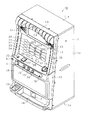
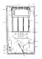
以下、遊技機の一種である回胴式遊技機、具体的にはスロットマシンに適用した場合の一実施の形態を、図面に基づいて詳細に説明する。図1はスロットマシン10の正面図、図2はスロットマシン10の前面扉12を閉じた状態の斜視図、図3はスロットマシン10の前面扉12を開いた状態の斜視図、図4は前面扉12の背面図、図5は筐体11の正面図である。
Hereinafter, an embodiment in the case of application to a spinning cylinder type gaming machine which is a kind of gaming machine, specifically, a slot machine will be described in detail based on the drawings. 1 is a front view of the
図1〜図5に示すように、スロットマシン10は、その外殻を形成する筐体11を備えている。筐体11は、木製板状に形成された天板11a、底板11b、背板11c、左側板11d及び右側板11eからなり、隣接する各板11a〜11eが接着等の固定手段によって固定されることにより、全体として前面を開放した箱状に形成されている。なお、各板11a〜11eは木製のパネルによって構成する以外に、合成樹脂製パネル又は金属製パネルによって構成してもよいし、合成樹脂材料又は金属材料によって一体の箱状に形成することによって構成してもよい。以上のように構成された筐体11は、遊技ホールへの設置の際にいわゆる島設備に対し釘を打ち付ける等して取り付けられる。
As shown in FIGS. 1 to 5, the
筐体11の前面側には、前面開閉扉としての前面扉12が開閉可能に取り付けられている。すなわち、筐体11の左側板11dには、上下一対の支軸25a,25bが設けられている。支軸25a,25bは上方に向けて突出された先細り形状の軸部を備えている。一方、前面扉12には、各支軸25a,25bに対応して当該支軸25a,25bの軸部が挿入される挿入孔を備えた支持金具26a,26bが設けられている。そして、各支軸25a,25bの上方に支持金具26a,26bを配置させた上で前面扉12を降下させることにより、支持金具26a,26bの挿入孔に支軸25a,25bの軸部が挿入された状態とされる。これにより、前面扉12は筐体11に対して両支軸25a,25bを結ぶ上下方向へ延びる開閉軸線を中心として回動可能に支持され、その回動によって筐体11の前面開放側を開放したり閉鎖することができるように構成されている。
A
前面扉12は、その裏面に設けられた施錠装置によって開放不能な施錠状態とされる。また、前面扉12の右端側上部には解錠操作部たるキーシリンダ20が設けられている。キーシリンダ20は施錠装置と一体化されており、キーシリンダ20に対する所定のキー操作によって前記施錠状態が解除されるように構成されている。そこで、施錠装置を含むロック機構について概略を説明する。
The
前面扉12の右端側、すなわち前面扉12の開閉軸の反対側には、その裏面に施錠装置が設けられている。施錠装置は、上下方向に延び前面扉12に固定された基枠と、基枠の上部から前面扉12の前方に延びるように設けられたキーシリンダ20と、基枠に対して上下方向に移動可能に組み付けられた長尺状の連動杆21とを備えている。そして、施錠装置のうちキーシリンダ20だけが前面扉12の前方に突出した状態で設けられている。キーシリンダ20が設けられる位置は前面扉12の中でも肉厚の薄い上部位置とされており、その結果、全長の短い汎用性のあるキーシリンダ20を採用することができる。なお、本実施の形態では、キーシリンダ20として、不正解錠防止機能の高いオムロック(商標名)が用いられている。連動杆21は、キーシリンダ20に差し込んだキーを時計回りに操作することで下方へ移動される。連動杆21には、鉤形状をなす上下一対の鉤金具22が設けられており、筐体11に対して前面扉12を閉鎖した際には、鉤金具22が筐体11側の支持金具23に係止されて施錠状態となる。なお、鉤金具22には施錠状態を維持する側へ付勢するコイルバネ等の付勢部材が設けられている。キーシリンダ20に対してキーが時計回りに操作されると、連動杆21が下方に移動し、前記付勢部材の付勢力に抗して鉤金具22が移動されることにより当該鉤金具22と支持金具23との係止状態が解除され、筐体11に対する前面扉12の施錠状態が解除される。
On the right end side of the
前面扉12の中央部上寄りには、遊技者に遊技状態を報知する遊技パネル30が設けられている。遊技パネル30には、縦長の3つの表示窓31L,31M,31Rが横並びとなるように形成されている。表示窓31L,31M,31Rは透明又は半透明な材質により構成されており、各表示窓31L,31M,31Rを通じてスロットマシン10の内部が視認可能な状態となっている。なお、各表示窓31L,31M,31Rを1つにまとめて共通の表示窓としてもよい。
A
図3に示すように、筐体11は仕切り板40によりその内部が上下2分割されており、仕切り板40の上部には、可変表示手段を構成するリールユニット41が取り付けられている。リールユニット41は、円筒状(円環状)にそれぞれ形成された左リール42L,中リール42M,右リール42Rを備えている。なお、各リール42L,42M,42Rは少なくとも無端状ベルトとして構成されていればよく、円筒状(円環状)に限定されるものではない。各リール42L,42M,42Rは、その中心軸線が当該リールの回転軸線となるように回転可能に支持されている。各リール42L,42M,42Rの回転軸線は略水平方向に延びる同一軸線上に配設され、それぞれのリール42L,42M,42Rが各表示窓31L,31M,31Rと1対1で対応している。従って、各リール42L,42M,42Rの表面の一部はそれぞれ対応する表示窓31L,31M,31Rを通じて視認可能な状態となっている。また、リール42L,42M,42Rが正回転すると、各表示窓31L,31M,31Rを通じてリール42L,42M,42Rの表面は上から下へ向かって移動しているかのように映し出される。
As shown in FIG. 3, the inside of the
これら各リール42L,42M,42Rは、それぞれがステッピングモータ61L,61M,61Rに連結されており、各ステッピングモータ61L,61M,61Rの駆動により各リール42L,42M,42Rが個別に、即ちそれぞれ独立して回転駆動し得る構成となっている。これら各リール42L,42M,42Rは同様の構成をしているため、ここでは左リール42Lを例に挙げて図6に基づいて説明する。なお、図6は左リール42Lの組立斜視図である。
Each of the
左リール42Lは、円筒状のかごを形成する円筒骨格部材50と、その外周面において無端状に巻かれた帯状のベルトとを備えている。そして、その巻かれた状態を維持するように、ベルトの長辺両側に沿って形成された一対のシール部を介して円筒骨格部材50に貼付されている。前記ベルトの外周面には、識別情報としての図柄が等間隔ごとに多数印刷されている。円筒骨格部材50の中心部にはボス部51形成されており、円盤状のボス補強板52を介して左リール用ステッピングモータ61Lの駆動軸に取り付けられている。従って、左リール用ステッピングモータ61Lの駆動軸が回転することによりその駆動軸を中心として円筒骨格部材50が自転するように回転され、左リール42Lが円環状のリール面に沿って周回するようになっている。
The
左リール用ステッピングモータ61Lは、リールユニット41(図3)内において起立状態に配置されたモータプレート53の側面にねじ54で固定されている。モータプレート53には、発光素子55aと受光素子55bとが所定間隔をおいて保持されたリールインデックスセンサ(回転位置検出センサ)55が設置されている。一方、左リール42Lと一体化されたボス補強板52には、半径方向に延びるセンサカットバン56の基端部56bがねじ57で固定されている。このセンサカットバン56の先端部56aは、略直角に屈曲されてリールインデックスセンサ55の両素子55a,55bの間を通過できるように位置合わせがなされている。そして、左リール42Lが1回転するごとにセンサカットバン56の先端部56aの通過をリールインデックスセンサ55が検出し、その検出の都度、後述する主制御装置131に検出信号が出力される。従って、主制御装置131はこの検出信号に基づいて左リール42Lの角度位置を1回転ごとに確認し補正できる。
The left
ステッピングモータ61Lは例えば504パルスの駆動信号(励磁信号あるいは励磁パルスとも言う。以下同じ)を与えることにより1回転されるように設定されており、この励磁パルスによってステッピングモータ61Lの回転位置、すなわち左リール42Lの回転位置が制御される。
The stepping
各リール42L,42M,42Rの各ベルト上には、その長辺方向(周回方向)に複数個、具体的には21個の図柄が描かれている。従って、所定の位置においてある図柄から次の図柄へ切り替えるには24パルス(=504パルス÷21図柄)を要する。そして、リールインデックスセンサ55の検出信号が出力された時点からのパルス数により、どの図柄が表示窓31Lから視認可能な状態となっているかを認識したり、任意の図柄を露出窓31Lから視認可能な状態としたりする制御を行うことができる。
On each belt of each of the
各リール42L,42M,42Rに付された図柄のうち、表示窓31L,31M,31Rを介して全体を視認可能な図柄数は、主として表示窓31L,31M,31Rの上下方向の長さによって決定される所定数に限られている。本実施形態では各リール3個ずつとされている。このため、各リール42L,42M,42Rがすべて停止している状態では、3×3=9個の図柄が遊技者に視認可能な状態となる。
Of the symbols attached to the
ここで、各リール42L,42M,42Rに付される図柄について説明する。図7には、左リール42L,中リール42M,右リール42Rのそれぞれに巻かれるベルトに描かれた図柄配列が示されている。同図に示すように、各リール42L,42M,42Rにはそれぞれ21個の図柄が一列に設けられている。各リール42L,42M,42Rに対応して番号が1〜21まで付されているが、これは説明の便宜上付したものであり、リール42L,42M,42Rに実際に付されているわけではない。但し、以下の説明では当該番号を使用して説明する。
Here, the symbols attached to the
図柄としては、ビッグボーナスゲームに移行するための第1特別図柄としての「7」図柄(例えば、左ベルト第20番目)と「青年」図柄(例えば、左ベルト19番目)とがある。また、レギュラーボーナスゲームに移行するための第2特別図柄としての「BAR」図柄(例えば、左ベルト第14番目)がある。また、リプレイゲームに移行するための第3特別図柄としての「リプレイ」図柄(例えば、左ベルト第11番目)がある。また、小役の払出が行われる小役図柄としての「スイカ」図柄(例えば、左ベルト第9番目)、「ベル」図柄(例えば、左ベルト第8番目)、「チェリー」図柄(例えば、左ベルト第4番目)がある。そして、図7に示すように、各リール42L,42M,42Rに巻かれるベルトにおいて、各種図柄の数や配置順序は全く異なっている。
As the symbols, there are a “7” symbol (for example, the left belt 20th) and a “youth” symbol (for example, the left belt 19th) as the first special symbol for shifting to the big bonus game. In addition, there is a “BAR” symbol (for example, the 14th left belt) as the second special symbol for shifting to the regular bonus game. Further, there is a “replay” symbol (for example, the eleventh left belt) as a third special symbol for shifting to the replay game. In addition, a “watermelon” symbol (for example, the left belt ninth), a “bell” symbol (for example, the left belt eighth), and a “cherry” symbol (for example, left) as the small character symbols from which the small character is paid out. Belt 4th). As shown in FIG. 7, the number of various symbols and the arrangement order are completely different in the belt wound around each
なお、リールユニット41の各リール42L,42M,42Rは識別情報を可変表示する可変表示手段の一例であり、主表示部を構成する。但し、可変表示手段はこれ以外の構成であってもよい。例えば、ベルトを自転させるのではなく周回させるタイプ等の他の機械的なリール構成としてもよく、また、機械的なリール構成に代えて、或いはこれに加えて、液晶表示器、ドットマトリックス表示器等の電気的表示により識別情報を可変表示させるものを設けてもよく、この場合は表示形態に豊富なバリエーションをもたせることが可能となる。
Each
遊技パネル30には、各表示窓31L,31M,31Rを結ぶようにして、横方向へ平行に3本、斜め方向へたすき掛けに2本、計5本の組合せラインが付されている。勿論、最大組合せライン数を6以上としてもよく、5未満としてもよく、所定条件に応じて最大組合せライン数を変更するようにしてもよい。これら各組合せラインに対応して、表示窓31L,31M,31R群の正面から見て左側には有効ライン表示部32,33,34が設けられている。第1有効ライン表示部32は組合せラインのうち中央の横ライン(中央ライン)が有効化された場合に点灯等によって表示報知される。第2有効ライン表示部33は組合せラインのうち上下の横ライン(上ライン及び下ライン)が有効化された場合に点灯等によって表示報知される。第3有効ライン表示部34は組合せラインのうち一対の斜めライン(右下がりライン及び右上がりライン)が有効化された場合に点灯等によって表示報知される。そして、有効化された組合せライン、すなわち有効ライン上に図柄が所定の組合せで停止した場合に入賞となり、予め定められたメダル払出処理や特定遊技への移行処理などが実行される。
A total of five combination lines are attached to the
ここで、入賞となった場合の各図柄に関する払出枚数について説明する。小役図柄に関し、「スイカ」図柄が有効ライン上に左・中・右と揃った場合には15枚のメダル払出、「ベル」図柄が有効ライン上に左・中・右と揃った場合には8枚のメダル払出、左リール42Lの「チェリー」図柄が有効ライン上に停止した場合には2枚のメダル払出が行われる。即ち、中リール42M及び右リール42Rの「チェリー」図柄はメダル払出と無関係である。また、「チェリー」図柄に限っては、他の図柄との組合せとは無関係にメダル払出が行われるため、左リール42Lの複数の有効ラインが重なる位置(具体的には上段又は下段)に「チェリー」図柄が停止した場合には、その重なった有効ラインの数を乗算した分だけのメダル払出が行われることとなり、結果として本実施の形態では4枚のメダル払出が行われる。
Here, the payout number regarding each symbol when winning is explained. Regarding the small role design, when the “Watermelon” design is aligned with the left, middle and right on the active line, 15 medals are paid out. When the “Bell” design is aligned with the left, middle and right on the effective line Pays out 8 medals, and when the “cherry” symbol on the
また、その他の図柄に関しては、第1特別図柄(ビッグボーナス図柄)の組合せである「7」図柄又は「青年」図柄が同一図柄にて有効ライン上に左・中・右と揃った場合には15枚のメダル払出、第2特別図柄(レギュラーボーナス図柄)の組合せである「BAR」図柄が有効ライン上に左・中・右と揃った場合にも15枚のメダル払出が行われる。なお、本実施形態においては、例えば「7」図柄と「チェリー」図柄とが同時に成立する場合が生じ得るが、かかる場合におけるメダル払出は15枚である。これは、1回のメダル払出における上限枚数が15枚に設定されているためである。 As for other symbols, when the “7” symbol or “youth” symbol, which is a combination of the first special symbol (big bonus symbol), is aligned with the left, middle and right on the active line in the same symbol The 15 medals are also paid out when the “BAR” symbol which is a combination of 15 medal payouts and the second special symbol (regular bonus symbol) is aligned with the left, middle and right on the active line. In the present embodiment, for example, a case where the “7” symbol and the “cherry” symbol are established simultaneously may occur, but in this case, 15 medals are paid out. This is because the upper limit number for one medal payout is set to 15.
更に、第3特別図柄の組合せである「リプレイ」図柄が有効ライン上に左・中・右と揃った場合にはメダル払出は行われない。その他の場合、即ち有効ライン上に左リール42Lの「チェリー」図柄が停止せず、また有効ライン上に左・中・右と同一図柄が揃わない場合には、一切メダル払出は行われない。
Further, when the “replay” symbol, which is the combination of the third special symbol, is aligned with the left, middle, and right on the active line, the medal payout is not performed. In other cases, that is, when the “cherry” symbol of the
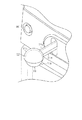
遊技パネル30の下方左側には、各リール42L,42M,42Rを一斉(同時である必要はない)に回転開始させるために操作されるスタートレバー71が設けられている。スタートレバー71はリール42L,42M,42Rを回転開始、すなわち可変表示を開始させるべく操作される開始操作手段又は始動操作手段を構成する。図8に拡大して示したように、スタートレバー71は、遊技者がゲームを開始するときに下方向へ手で押し操作するレバーであり、前方に突出する棒状に形成されたレバー部71aと、同レバー部71aの先端部に設けられた球形状をなす球体71bとを有する。この球体71bが設けられていることにより、スタートレバー71の操作性が単にレバー部71aだけの場合よりも高められている。そして、スタートレバー71は同レバー71を手で押し操作した後、手が離れると元の位置に自動復帰するように構成されている。前記メダルが投入されているときにこのスタートレバー71が操作されると、各リール42L,42M,42Rが一斉に回転を始める。なお、開始操作手段又は始動操作手段としては、レバーに限定されず、ボタン状のスイッチ等他の構成を採用してもよい。
On the lower left side of the
スタートレバー71の右側には、回転している各リール42L,42M,42Rを個別に停止させるために操作されるボタン状のストップスイッチ72,73,74が設けられている。各ストップスイッチ72,73,74は停止対象となるリール42L,42M,42Rに対応する表示窓31L,31M,31Rの直下にそれぞれ配置されている。ストップスイッチ72,73,74はリール42L,42M,42Rの回転に基づく可変表示を停止させるべく操作される停止操作手段を構成する。各ストップスイッチ72,73,74は、各リール42L,42M,42Rが等速回転となると停止させることが可能な状態となり、かかる状態中には図示しないランプが点灯表示されることによって停止操作が可能であることが報知され、回転が停止すると消灯されるようになっている。
On the right side of the
表示窓31L,31M,31Rの下方右側には、投資価値としてのメダルを投入するためのメダル投入口75が設けられている。メダル投入口75は投資価値を入力する入力手段を構成する。また、メダル投入口75が遊技者によりメダルを直接投入するという動作を伴う点に着目すれば、投資価値を直接入力する直接入力手段を構成するものともいえる。
On the lower right side of the
メダル投入口75から投入されたメダルは、前面扉12の背面に設けられた通路切替手段としてのセレクタ84によって貯留用通路81か排出用通路82のいずれかへ導かれる。すなわち、セレクタ84にはメダル通路切替ソレノイド83が設けられ、そのメダル通路切替ソレノイド83の非励磁時には排出用通路82側とされ、励磁時には貯留用通路81側に切り替えられるようになっている。貯留用通路81に導かれたメダルは、筐体11の内部に収納されたホッパ装置91へと導かれる。一方、排出用通路82に導かれたメダルは、前面扉12の前面下部に設けられたメダル排出口17からメダル受け皿18へと導かれ、遊技者に返還される。
The medals inserted from the
メダルを遊技者に付与する払出手段としてのホッパ装置91は、メダルを貯留する貯留タンク92と、メダルを遊技者に払い出す払出装置93とより構成されている。払出装置93は、図示しないメダル払出用回転板を回転させることにより、排出用通路82の中央右部に設けられた開口94へメダルを排出し、排出用通路82を介してメダル受け皿18へメダルを払い出すようになっている。また、ホッパ装置91の右方には、貯留タンク92内に所定量以上のメダルが貯留されることを回避するための予備タンク95が設けられている。ホッパ装置91の貯留タンク92内部には、この貯留タンク92から予備タンク95へとメダルを排出する誘導プレート96が設けられている。したがって、誘導プレート96が設けられた高さ以上にメダルが貯留された場合、かかるメダルが予備タンク95に貯留されることとなる。
A
メダル投入口75の下方には、ボタン状の返却スイッチ76が設けられている。返却スイッチ76は、メダル投入口75に投入されたメダルがセレクタ84内に詰まった際に押されるスイッチであり、このスイッチが押されることによりセレクタ84が機械的に連動して動作され、当該セレクタ84内に詰まったメダルがメダル排出口17より返却されるようになっている。
A button-like return switch 76 is provided below the
図8に拡大して示したように、前記スタートレバー71の上側には、投資価値としてのクレジットされた仮想メダルを投入するための第1クレジット投入スイッチ77が設けられている。第1クレジット投入スイッチ77はベットレバーであり、また前記メダル投入口75とともに投資価値を入力する入力手段を構成している。この第1クレジット投入スイッチ77は下方向へ手で押し操作されるスイッチであり、スタートレバー71のレバー部71a及び球体71bに対応して、前方に突出する樋形状に形成された基部77aと、その先端に略半球形状に形成されたボウル部77bとを有している。この基部77aとボウル部77bの内面は、同内面によって形成される空間部の形状がそれぞれレバー部71aと球体71bの外形に合わせて形成されている。そして、基部77aはレバー部71aに、ボウル部77bは球体71bに、その上部に被さるようにして設けられている。また、第1クレジット投入スイッチ77は同スイッチ77を手で押し操作した後、手が離れると元の位置に自動復帰するように構成されている。この押し操作の際には、ボウル部77bが略半球形状に形成され、スタートレバー71の球体71bの上側略半分が覆われていることから、第1クレジット投入スイッチ77のボウル部77bに多少無理な力が作用しても、第1クレジット投入スイッチ77がスタートレバー71に被せられた状態から外れる可能性は小さくなっている。なお、前記基部77a及び前記ボウル部77bの外形はその内面形状と同一である必要はない。
As shown in an enlarged view in FIG. 8, a first
表示窓31L,31M,31Rの下方左側には、ボタン状の投入数切換スイッチ78が設けられている。投入数切換スイッチ78は第1クレジット投入スイッチ77による仮想メダルの投入枚数を切り換えるスイッチであり、ベット機能切換手段を構成している。この投入数切換スイッチ78は、1度押されるとその押されて凹んだ状態が維持されてオン状態になり、もう1度押されると元の状態に戻ってオフ状態になり、その後押下操作が行われるごとにオンオフが切り替わるトグル式に構成されている。
On the lower left side of the
かかる切換スイッチ78がオフ状態で第1クレジット投入スイッチ77を操作すると仮想メダルが1度に3枚投入され、オン状態では1枚投入されるように構成されている。すなわち、投入数切換スイッチ78により、仮想メダルを3枚投入する機能と、仮想メダルを1枚投入する機能とが切り換えられることになる。これらの機能は、最大投入可能枚数(本実施形態では3枚)を投入するマックスベット機能と、最大投入可能枚数未満の所定枚数を投入する特定ベット機能となっている。
When the first
そして、この投入数切換スイッチ78には「MAXBET」と表記されるとともに図示しないランプが内蔵されており、同スイッチ78がオフ状態にある場合のみランプが点灯するように構成されている。従って、投入数切換スイッチ78がオフ状態であると、同スイッチ78はランプの点灯により「MAXBET」と明るく表示される。この表示により、現状がオフ状態であって第1クレジット投入スイッチ77の操作による投入枚数が3枚であると遊技者は容易に判断できる。
The number-of-
なお、投入数切換スイッチ78はシーソー式のスイッチとする等、前述したトグル式以外のスイッチでもよいし、オンオフ状態と投入枚数との関係は前述した場合と逆であってもよい。また、ランプが点灯する状態は前述した場合と逆に投入数切換スイッチ78がオン状態の場合であってもよい。そして、オンオフ状態と投入枚数との関係やランプの点灯状態を変更した場合には、その構成によっては投入数切換スイッチ78に表記される文字が「1BET」となる場合もある。
It should be noted that the insertion
表示窓31L,31M,31Rの下方左側には、ボタン状の第2クレジット投入スイッチ79が設けられている。第2クレジット投入スイッチ79はクレジットされた仮想メダルを一度に2枚投入するためのものである。第2クレジット投入スイッチ79は前記メダル投入口75とともに投資価値を入力する入力手段を構成する。ここで、前述したように第1クレジット投入スイッチ77も入力手段の一つである。メダル投入口75が遊技者によりメダルを直接投入するという動作を伴うのに対し各クレジット投入スイッチ77,79は貯留記憶に基づく仮想メダルの投入という動作を伴うに過ぎない点に着目すれば、投資価値を間接入力する間接入力手段を構成するものともいえる。
A button-like second
スタートレバー71の左側には、ボタン状の切換スイッチ80が設けられている。切換スイッチ80は、1度押されるとオン状態になり、もう1度押されるとオフ状態になり、その後押下操作が行われるごとにオンオフが切り替わるトグル式に構成されている。切換スイッチ80は、メダル投入口75に必要量より多く投入された投入メダルや、所定の遊技の結果遊技者に返還される獲得メダルの取扱形式を変更するために操作される。
A button-like changeover switch 80 is provided on the left side of the
切換スイッチ80がオン状態のときには、所定の最大値(例えばメダル50枚分)となるまでの余剰の投入メダルや入賞時の獲得メダルがクレジットメダルとして貯留記憶されるように設定された「クレジットモード」となる。切換スイッチ80がオフ状態のときには、余剰の投入メダルや入賞時の獲得メダルを現実のメダルとして払い出すように設定された「ダイレクトモード」となる。なお、クレジットモードからダイレクトモードに切り換えられた際にクレジットメダルがある場合には、その分のクレジットメダルが現実のメダルとして払い出される。このように、遊技者はクレジットモードとダイレクトモードとを切り換えることにより自身の好みに応じた形式で遊技を実行することができる。かかる切換スイッチ80は投入価値及び遊技価値の取扱形式を切り換える切換操作手段を構成する。また、クレジットされた仮想メダルを現実のメダルとして払い出すという機能に着目すれば、切換スイッチ80は貯留記憶された遊技価値を実際に払い出すための精算操作手段を構成するものともいえる。なお、切換スイッチ80の操作により「クレジットモード」と「ダイレクトモード」とを切り換えるように構成する他、常に「クレジットモード」としておき切換スイッチ80が操作されると貯留記憶された仮想メダルを払い出すだけの精算スイッチとして機能させてもよい。
When the change-
遊技パネル30の表示窓31L,31M,31R下方には、クレジットモード時に有効化されて貯留記憶されたメダル数を表示する残数表示部35と、ビッグボーナスやレギュラーボーナス等の特別遊技状態の際に例えば残りのゲーム数等を表示するゲーム数表示部36と、獲得メダルの枚数を表示する獲得枚数表示部37とがそれぞれ設けられている。これら表示部35〜37は7セグメント表示器によって構成されているが、液晶表示器等によって代替することは当然可能である。
Below the
ここで、メダルがベットされる手順について説明する。ダイレクトモード、クレジットモードのいずれのモードにおいても、遊技の開始時にメダル投入口75からメダルが投入されるとベットとなる。
Here, a procedure for betting medals will be described. In both the direct mode and the credit mode, a bet is made when a medal is inserted from the
すなわち、1枚目のメダルがメダル投入口75に投入されると、第1有効ライン表示部32が点灯し、そしてこれに対応する中央ラインが有効ラインとなり、2枚目のメダルがメダル投入口75に投入されると、更に第2有効ライン表示部33が点灯すると共に、これに対応する上ライン及び下ラインを含む合計3本の組合せラインがそれぞれ有効ラインとなり、3枚目のメダルがメダル投入口75に投入されると、更に第3有効ライン表示部34が点灯し、そしてこれに対応する一対の斜めラインを含む合計5本の組合せライン全てが有効ラインとなる。
That is, when the first medal is inserted into the
また、4枚以上のメダルがメダル投入口75に投入されると、3枚を超える余剰メダルは、そのときのモードがダイレクトモードであればセレクタ84により排出用通路82への切替がなされてメダル排出口17からメダル受け皿18へ返却される。一方、クレジットモードであればスロットマシン内部に貯蓄されると共に残数表示部35に貯蓄枚数が表示される。この貯留枚数には上限枚数が決められており(例えば50枚)、それを越える枚数のメダルが投入されたときにはメダル排出口17からメダル受け皿18へ返却される。
When four or more medals are inserted into the
また、クレジットモードにて遊技が行われ且つ残数表示部35に貯留枚数が表示されている場合には、第1、第2クレジット投入スイッチ77,79のいずれかが操作された際にも仮想メダルが投入されたこととなりベットとなる。
In addition, when a game is played in the credit mode and the number of stored items is displayed on the remaining
投入数切換スイッチ78がオン状態にあるときに、第1クレジット投入スイッチ77が下方向へ手で押し操作されると、仮想メダルが1枚投入されたこととして残数表示部35に表示されている数値が1つディクリメントされ、第1有効ライン表示部32が点灯して中央ラインが有効ラインとなる。第2クレジット投入スイッチ79が押された際には、仮想メダルが2枚投入されたこととして残数表示部35に表示されている数値が2つディクリメントされ、第1有効ライン表示部32および第2有効ライン表示部33が点灯して合計3本の組合せラインが有効ラインとなる。投入数切換スイッチ78がオフ状態にあるときに、第1クレジット投入スイッチ77が下方向へ手で押し操作されると、仮想メダルが3枚投入されたこととして残数表示部35に表示されている数値が3つディクリメントされ、全ての有効ライン表示部32〜34が点灯して合計5本の組合せラインが有効ラインとなる。
When the first
なお、第1、第2クレジット投入スイッチ77,79のいずれかが押された際に投入されるべき仮想メダルが貯留されていない場合、例えば残数表示部35の表示が2のときに、投入数切換スイッチ78がオフ状態で、第1クレジット投入スイッチ77が押し操作された場合(3枚投入操作)等には、残数表示部35の数値が全てディクリメントされて0となり、投入可能な仮想メダル分だけベットされる。
In addition, when the virtual medal to be inserted when any of the first and second credit insertion switches 77 and 79 is pressed is not stored, for example, when the display of the remaining
そして、スタートレバー71の上部に被せられた第1クレジット投入スイッチ77が下方向へ手で押し操作されると、その動作に伴ってスタートレバー71も手で押し操作されることになる。このため、第1クレジット投入スイッチ77とスタートレバー71の操作により、1枚又は3枚の仮想メタルがベットされるのに続き、各リール42L,42M,42Rが一斉に回転開始される。すなわち、遊技者が片手を一度振り下ろす動作をするだけで、第1クレジット投入スイッチ77、スタートレバー71の順で、それらが連続して操作されることになる。
When the first
他方、第2クレジット投入スイッチ79が押された場合も、スタートレバー71を手で押し操作する際には、同スタートレバー71の上部に被せられた第1クレジット投入スイッチ77が手で押し操作されることになる。このとき、投入数切換スイッチ78がオフ状態で「MAXBET」と明るく表示されている状態であれば、第1クレジット投入スイッチ77の操作による3枚ベットが優先される。逆に、投入数切換スイッチ78がオン状態であれば第1クレジット投入スイッチ77の操作による1枚ベットよりも、第2クレジット投入スイッチ79の操作による2枚ベットが優先される。
On the other hand, even when the second
前面扉12の上部には、遊技の進行に伴い点灯したり点滅したりする上部ランプ13と、遊技の進行に伴い種々の効果音を鳴らしたり、遊技者に遊技状態を報知したりする左右一対のスピーカ14と、遊技者に各種情報を与える補助表示部15とが設けられている。補助表示部15は、本実施形態では表示内容の多様化及び表示演出の重厚化を意図して液晶表示器によって構成されているが、ドットマトリックス表示器等の他の表示器を使用してもよい。補助表示部15は、遊技の進行に伴って各種表示演出を実行するためのものであり、各リール42L,42M,42Rによる遊技を主表示部によるものと考えることができることから、本実施形態では補助表示部15と称している。補助表示部15の背面には上部ランプ13やスピーカ14、補助表示部15を駆動させるための表示制御装置111が設けられている。なお、上部ランプ13及びスピーカ14の位置や数は特に以上説明したものに限られない。
On the upper part of the
メダル受け皿18の上方には、機種名や遊技に関わるキャラクタなどが表示された下段プレート16が装着されている。また、メダル受け皿18の左方には、手前側下方に反転可能な灰皿19が設けられている。
A
筐体11の内部においてホッパ装置91の左方には、電源ボックス121が設けられている。電源ボックス121は、電源スイッチ122やリセットスイッチ123や設定キー挿入孔124などを備えている。電源スイッチ122は、主制御装置131を始めとする各部に電源を供給するための起動スイッチである。
A
リセットスイッチ123は、スロットマシン10の各種状態をリセットするためのスイッチである。本スロットマシン10は各種データのバックアップ機能を有しており、万一停電が発生した際でも停電時の状態を保持し、停電からの復帰(復電)の際には停電時の状態に復帰できるようになっている。従って、例えば遊技ホールの営業が終了する場合のように通常手順で電源を遮断すると遮断前の状態が記憶保持されるが、リセットスイッチ123を押しながら電源スイッチ122をオンすると、バックアップデータがリセットされるようになっている。また、電源スイッチ122がオンされている状態でリセットスイッチ123を押した場合には、エラー状態がリセットされる。
The
設定キー挿入孔124は、ホール管理者などがメダルの出玉調整を行うためのものである。すなわち、ホール管理者等が設定キーを設定キー挿入孔124へ挿入して操作することにより、スロットマシン10の設定状態(当選確率設定処理)を「設定1」から「設定6」まで変更できるようになっている。
The setting
リールユニット41の上方には、主制御装置131が筐体11の背板11cに取り付けられている。主制御装置131は、主たる制御を司るCPU、遊技プログラムを記憶したROM、遊技の進行に応じた必要なデータを一時的に記憶するRAM、各種機器との連絡をとるポート、時間計数や同期を図る場合などに使用されるクロック回路等を含む主基板を具備しており、主基板が透明樹脂材料等よりなる被包手段としての基板ボックスに収容されて構成されている。なお、基板ボックスは、略直方体形状のボックスベースと該ボックスベースの開口部を覆うボックスカバーとを備えている。これらボックスベースとボックスカバーとは封印手段としての封印ユニットによって開封不能に連結され、これにより基板ボックスが封印されている。
A
次に、本スロットマシン10の電気的構成について、図9のブロック図に基づいて説明する。
Next, the electrical configuration of the
主制御装置131には、演算処理手段であるCPU151を中心とするマイクロコンピュータが搭載されている。CPU151には、電源ボックス121の内部に設けられた電源装置161の他に、所定周波数の矩形波を出力するクロック回路154や、入出力ポート155などが内部バスを介して接続されている。かかる主制御装置131は、スロットマシン10に内蔵されるメイン基盤としての機能を果たすものである。
The
主制御装置131の入力側には、スタートレバー71の操作を検出するスタート検出センサ71a、各ストップスイッチ72,73,74の操作を個別に検出するストップ検出センサ72a,73a,74a、メダル投入口75から投入されたメダルを検出する投入メダル検出センサ75a、各クレジット投入スイッチ77,79の操作を個別に検出するクレジット投入検出センサ77a,79a、投入数切換スイッチ78の操作を検出する投入数切換検出センサ78a、切換スイッチ80の操作を検出する切換検出センサ80a、各リール42の回転位置(原点位置)を個別に検出するリールインデックスセンサ55、ホッパ装置91から払い出されるメダルを検出する払出検出センサ91a、リセットスイッチ123の操作を検出するリセット検出センサ123a、設定キー挿入孔124に設定キーが挿入されたことを検出する設定キー検出センサ124a等の各種センサが接続されており、これら各種センサからの信号は入出力ポート155を介してCPU151へ出力されるようになっている。
On the input side of the
なお、投入メダル検出センサ75aは実際には複数個のセンサより構成されている。即ち、メダル投入口75からホッパ装置91に至る貯留用通路81は、メダルが1列で通行可能なように構成されている。そして、貯留用通路81には第1センサが設けられるとともに、それよりメダルの幅以上離れた下流側に第2センサ及び第3センサが近接(少なくとも一時期において同一メダルを同時に検出する状態が生じる程度の近接)して設けられており、これら第1乃至第3の各センサによって投入メダル検出センサ75aが構成されている。主制御装置131は、第1センサから第2センサに至る時間を監視し、その経過時間が所定時間を越えた場合にはメダル詰まり又は不正があったものとみなしてエラーとする。エラーになると、エラー報知が行われるとともにエラー解除されるまでの遊技者による操作が無効化される。また、主制御装置131は第2センサと第3センサとがオンオフされる順序をも監視し、第2,第3センサが共にオフ、第2センサのみオン、第2,第3センサが共にオン、第3センサのみオン、第2,第3センサが共にオフという順序通りになった場合で、かつ各オンオフ切換に移行する時間が所定時間内である場合にのみメダルが正常に取り込まれたと判断し、それ以外の場合はエラーとする。このようにするのは、貯留用通路81でのメダル詰まりの他、メダルを投入メダル検出センサ75a付近で往復動させてメダル投入と誤認させる不正を防止するためである。
The inserted medal detection sensor 75a is actually composed of a plurality of sensors. That is, the
また、主制御装置131の入力側には、入出力ポート155を介して電源装置161に設けられた停電監視回路161bが接続されている。電源基板161には、主制御装置131を始めとしてスロットマシン10の各電子機器に駆動電力を供給する電源部161aや、上述した停電監視回路161bなどが搭載されている。
Further, a power
停電監視回路161bは電源の遮断状態を監視し、停電時はもとより、電源スイッチ122による電源遮断時に停電信号を生成するためのものである。そのため停電監視回路161bは、電源部161aから出力されるこの例では直流24ボルトの安定化駆動電圧を監視し、この駆動電圧が例えば22ボルト未満まで低下したとき電源が遮断されたものと判断して停電信号が出力されるように構成されている。停電信号はCPU151と入出力ポート155のそれぞれに供給され、CPU151ではこの停電信号を認識することにより後述する停電時処理が実行される。
The power
電源部161aからは出力電圧が22ボルト未満まで低下した場合でも、主制御装置131などの制御系における駆動電圧として使用される5ボルトの安定化電圧が出力されるように構成されており、この安定化電圧が出力されている時間としては、主制御装置131による停電時処理を実行するに十分な時間が確保されている。
Even when the output voltage drops below 22 volts, the
主制御装置131の出力側には、各有効ライン表示部32,33,34、残数表示部35、ゲーム数表示部36、獲得枚数表示部37、各リール42L,42M,42Rを回転させるための各ステッピングモータ61(61L,61M,61R)、セレクタ84に設けられたメダル通路切替ソレノイド83、ホッパ装置91、表示制御装置111、図示しないホール管理装置などに情報を送信できる外部集中端子板171等が入出力ポート155を介して接続されている。
On the output side of the
表示制御装置111は、上部ランプ13やスピーカ14、補助表示部15を駆動させるための制御装置であり、これらを駆動させるためのCPU、ROM、RAM等が一体化された基板を備えている。そして、主制御装置131からの信号を受け取った上で、表示制御装置111が独自に上部ランプ13、スピーカ14及び補助表示部15を駆動制御する。従って、表示制御装置111は、遊技を統括管理するメイン基盤たる主制御装置131との関係では補助的な制御を実行するサブ基盤となっている。即ち、間接的な遊技に関する音声やランプ、表示についてはサブ基盤を設けることにより、メイン基盤の負担軽減を図っている。なお、各種表示部32〜37を表示制御装置111が制御する構成としてもよい。
The
上述したCPU151には、このCPU151によって実行される各種の制御プログラムや固定値データを記憶したROM152と、このROM152内に記憶されている制御プログラムを実行するに当たって各種のデータを一時的に記憶する作業エリアを確保するためのRAM153のほかに、図示はしないが周知のように割込み回路を始めとしてタイマ回路、データ送受信回路などスロットマシン10において必要な各種の処理回路や、クレジット枚数をカウントするクレジットカウンタなどの各種カウンタが内蔵されている。ROM152とRAM153によって記憶手段としてのメインメモリが構成され、図10以降に示される各種のフローチャートに示される処理を実行するためのプログラムは、制御プログラムの一部として上述したROM152に記憶されている。
The
RAM153は、スロットマシン10の電源が遮断された後においても電源ボックス121内に設けられた電源装置161からバックアップ電圧が供給されてデータを保持(バックアップ)できる構成となっており、RAM153には、各種のデータ等を一時的に記憶するためのメモリやエリアの他に、バックアップエリアが設けられている。
The
バックアップエリアは、停電などの発生により電源が遮断された場合において、電源遮断時(電源スイッチ122の操作による電源遮断をも含む。以下同様)のスタックポインタや、各レジスタ、I/O等の値を記憶しておくためのエリアであり、停電解消時(電源スイッチ122の操作による電源投入をも含む。以下同様)には、バックアップエリアの情報に基づいてスロットマシン10の状態が電源遮断前の状態に復帰できるようになっている。バックアップエリアへの書き込みは停電時処理(図12参照)によって電源遮断時に実行され、バックアップエリアに書き込まれた各値の復帰は電源投入時のメイン処理(図13参照)において実行される。なお、CPU151のNMI端子(ノンマスカブル割込端子)には、停電等の発生による電源遮断時に、停電監視回路161bからの停電信号が入力されるように構成されており、停電等の発生に伴う停電フラグ生成処理としてのNMI割込み処理が即座に実行される。
In the backup area, when the power is shut down due to the occurrence of a power failure or the like, the values of the stack pointer, each register, I / O, etc. when the power is shut down (including power shutdown by operating the
続いて、主制御装置131内のCPU151により実行される各制御処理を図10〜図19のフローチャートを参照しながら説明する。かかるCPU151の処理としては大別して、電源投入に伴い起動されるメイン処理と、定期的に(本実施の形態では1.49msec周期で)起動されるタイマ割込み処理と、NMI端子(ノンマスカブル端子)への停電信号の入力により起動されるNMI割込み処理とがあり、説明の便宜上、はじめにNMI割込み処理とタイマ割込み処理とを説明し、その後メイン処理を説明する。
Subsequently, each control process executed by the
図10はNMI割込み処理の一例を示すフローチャートである。停電の発生などによって電源が遮断されると、電源装置161の停電監視回路161bでは停電信号が生成され、主制御装置131に対して出力される。NMI端子を介して停電信号を受信した主制御装置131では、NMI割込み処理が実行される。
FIG. 10 is a flowchart showing an example of the NMI interrupt process. When the power is shut off due to the occurrence of a power failure or the like, the power
NMI割込み処理では、まずステップS101において、CPU151内に設けられた使用レジスタのデータをRAM153内に設けられたバックアップエリアに退避させる。続いて、ステップS102では、停電フラグをRAM153内に設けられた停電フラグ格納エリアにセットする。その後、ステップS103にてRAM153のバックアップエリアに退避させたデータを再びCPU151の使用レジスタに復帰させる。この復帰処理でNMI割込み処理が終了する。なお、CPU151の使用レジスタのデータを破壊せずに停電フラグのセット処理が可能な場合には、バックアップエリアへの退避および復帰処理を省くことができる。
In the NMI interrupt processing, first, in
図11は、主制御装置131で定期的に実行されるタイマ割込み処理のフローチャートであり、主制御装置131のCPU151により例えば1.49msecごとにタイマ割込みが発生する。
FIG. 11 is a flowchart of timer interrupt processing periodically executed by the
先ず、ステップS201に示すレジスタ退避処理では、後述する通常処理で使用しているCPU151内の全レジスタの値をRAM153のバックアップエリアに退避させる。ステップS202では停電フラグがセットされているか否かを確認し、停電フラグがセットされているときにはステップS203に進み、停電時処理を実行する。
First, in the register saving process shown in step S201, the values of all the registers in the
ここで、停電時処理について図12を用いて説明する。この停電時処理は、タイマ割込み処理のうち特にレジスタ退避処理の直後に行われるため、その他の割込み処理を中断することなく実行できる。従って、例えば各種コマンドの送信処理中、スイッチの状態(オンオフ)の読み込み処理中などのように、それぞれの処理に割り込んでこの停電時処理が実行されることはなく、かかるタイミングで実行されることをも考慮した停電時処理のプログラムを作成する必要がなくなる。これにより停電時処理用の処理プログラムを簡略化してプログラム容量を削減できる。なお、このことは後述する復電時処理用の処理プログラムについても同様である。 Here, the power failure process will be described with reference to FIG. Since the power failure process is performed immediately after the register saving process in the timer interrupt process, other interrupt processes can be executed without interruption. Therefore, for example, during the process of transmitting various commands, during the process of reading the switch state (on / off), the process at the time of power failure is not executed by interrupting each process. It is no longer necessary to create a power failure processing program that also takes into account This simplifies the processing program for power failure processing and reduces the program capacity. This also applies to a processing program for power recovery processing described later.
ステップS301では、コマンド送信が終了しているか否かを判定する。送信が終了していない場合には元の図11に戻る。このように停電時処理の初期段階でコマンドの送信が完了しているか否かを判断し、送信が未完であるときには送信処理を優先し、単位コマンドの送信処理終了後に停電時処理を実行する構成とすることにより、コマンドの送信途中で停電時処理が実行されることをも考慮した停電時処理プログラムを構築する必要がなくなる。その結果停電時処理プログラムを簡略化してROM152の小容量化を図ることができる実益を有する。
In step S301, it is determined whether command transmission has been completed. If the transmission has not ended, the process returns to the original FIG. In this way, it is determined whether or not the command transmission is completed at the initial stage of the power failure process, the transmission process is prioritized when the transmission is incomplete, and the power failure process is executed after the unit command transmission process is completed. By doing so, it is no longer necessary to construct a power failure processing program that takes into account that power failure processing is executed during command transmission. As a result, the power failure processing program can be simplified and the
ステップS301がYES、すなわちコマンドの送信が完了している場合には、ステップS302に進み、CPU151のスタックポインタの値をRAM153内のバックアップエリアに保存する。その後ステップS303では、停止処理として後述するRAM判定値をクリアすると共に入出力ポート155における出力ポートの出力状態をクリアし、図示しない全てのアクチュエータをオフ状態にする。ステップS304では、RAM判定値を算出し、バックアップエリアに保存する。RAM判定値とは、具体的にはRAM153の作業領域アドレスにおけるチェックサムの2の補数である。RAM判定値をバックアップエリアに保存することにより、RAM153のチェックサムは0となる。RAM153のチェックサムを0とすることにより、ステップS305においてそれ以後のRAMアクセスを禁止する。その後は、電源が完全に遮断して処理が実行できなくなるのに備え、無限ループに入る。
If step S301 is YES, that is, if the command transmission is completed, the process proceeds to step S302, and the value of the stack pointer of the
なお、電源装置161の電源部161aは、上述したNMI割込み処理及び停電時処理を実行するのに十分な時間、制御系の駆動電圧として使用される安定化電圧(5ボルト)の出力が保持されるように構成されている。本実施形態では、30msecの間、駆動電圧が出力され続けるようになっている。
The
タイマ割込み処理の説明に戻り、ステップS202にて停電フラグがセットされていない場合には、ステップS204以降の各種処理を行う。 Returning to the description of the timer interrupt process, if the power failure flag is not set in step S202, various processes after step S204 are performed.
すなわち、ステップS204では、誤動作の発生を監視するためのウオッチドッグタイマの値を初期化するウオッチドッグタイマのクリア処理を行う。ステップS205では、CPU151自身に対して割込み許可を出す割込み終了宣言処理を行う。ステップS206では、各リール42L,42M,42Rを回転させるために、それぞれの回胴駆動モータであるステッピングモータ61L〜61Rを駆動させるステッピングモータ制御処理を行う。ステップS207では、入出力ポート155に接続された各種センサ(図9参照)の状態を監視するセンサ監視処理を行う。ステップS208では、各カウンタやタイマの値を減算するタイマ演算処理を行う。ステップS209では、メダルのベット数や、払い出し枚数をカウントするカウンタ処理を行う。
That is, in step S204, a watchdog timer clearing process for initializing the value of the watchdog timer for monitoring the occurrence of malfunction is performed. In step S205, an interrupt end declaration process for giving an interrupt permission to the
ステップS210では、表示制御装置111へコマンドなどを送信するコマンド出力処理を行う。ステップS211では、残数表示部35、ゲーム数表示部36および獲得枚数表示部37にそれぞれ表示されるセグメントデータを設定するセグメントデータ設定処理を行う。ステップS212では、セグメントデータ設定処理で設定されたセグメントデータを各表示部35〜37に供給して該当する数字、記号などを表示するセグメントデータ表示処理を行う。ステップS213では、入出力ポート155からI/O装置に対応するデータを出力するポート出力処理を行う。ステップS214では、先のステップS201にてバックアップエリアに退避させた各レジスタの値をそれぞれCPU151内の対応するレジスタに復帰させる。その後ステップS215にて次回のタイマ割込みを許可する割込み許可処理を行い、この一連のタイマ割込み処理を終了する。
In step S210, command output processing for transmitting a command or the like to the
図13は電源投入後に実行される主制御装置131でのメイン処理を示すフローチャートである。メイン処理は、停電からの復旧や電源スイッチ122のオン操作によって電源が投入された際に実行される。
FIG. 13 is a flowchart showing a main process in the
先ずステップS401では、初期化処理として、スタックポインタの値をCPU151内に設定すると共に、割込み処理を許可する割込みモードを設定し、その後CPU151内のレジスタ群や、I/O装置等に対する各種の設定などを行う。
First, in step S401, as initialization processing, the value of the stack pointer is set in the
これらの初期化処理が終了すると、次にステップS402ではリセットスイッチ123がオン操作されているか否かを判定する。リセットスイッチ123がオン操作されている場合にはステップS403に進み、RAMクリア処理としてRAM153に記憶されたデータを全てクリアする。
When these initialization processes are completed, it is next determined in step S402 whether or not the
ステップS402にてリセットスイッチが操作されていないことを確認した後、またはステップS403にてRAMクリア処理を行った後、ステップS404では設定キーが設定キー挿入孔124に挿入されているか否かを判定する。設定キーが挿入されている場合にはステップS405に進み設定変更処理を行う。設定変更処理として、先ずRAM153に記憶されたデータを全てクリアする。そして、予め設定された6段階の設定状態(「設定1」〜「設定6」)のうちどの設定状態が選択されたかを判定した上で、選択された設定状態に応じた内部処理を実行する。
After confirming that the reset switch has not been operated in step S402 or performing a RAM clear process in step S403, it is determined in step S404 whether or not a setting key has been inserted into the setting
ステップS406では停電フラグがセットされているか否かを確認する。停電フラグがセットされていない、すなわち先のステップS403又はステップS405にてRAM153のデータがクリアされている場合には、後述するステップS407の通常処理に進み、本処理を終了する。
In step S406, it is confirmed whether or not a power failure flag is set. When the power failure flag is not set, that is, when the data in the
ステップS406において停電フラグがセットされた状態にあるときには、ステップS408以降に示す復電処理に移行する。停電フラグがセットされた状態にあるということは、ステップS403のRAMクリア処理、ステップS405の設定変更処理等のサブルーチン処理が全く実行されていないことを意味する。従って、RAM153のデータは全く書き替えられていないこととなり、復電処理ではRAM153のデータなどが正常であるかどうかなどの確認処理が必要となる。
When the power failure flag is set in step S406, the process proceeds to the power recovery process shown in step S408 and thereafter. The fact that the power failure flag is set means that subroutine processing such as RAM clear processing in step S403 and setting change processing in step S405 is not executed at all. Therefore, the data in the
そのためにまず、ステップS408ではRAM判定値が正常であるか否かを確認する。具体的には、RAM153のチェックサムの値を調べ、その値が正常、つまりRAM判定値を加味したチェックサムの値が0か否かを確認する。RAM判定値を加味したチェックサムの値が0である場合、RAM153のデータは正常であると判定する。
For this purpose, first, in step S408, it is confirmed whether or not the RAM determination value is normal. Specifically, the value of the checksum in the
ステップS408においてRAM判定値が異常である、つまりチェックサムの値が0でなかったときには、RAM153のデータが破壊された可能性が高い。そのため、このような場合にはステップS409にてエラー表示処理を行う。エラー表示処理として、先ず割込み処理を禁止し、入出力ポート155内の全ての出力ポートをクリアすることにより、入出力ポート155に接続された全てのアクチュエータをオフ状態に制御する。その後、ホール管理者などにエラーの発生を報知するエラー表示を行うと共に、リセットスイッチ123がON操作されるまでかかる状態を維持する。
If the RAM determination value is abnormal in step S408, that is, if the checksum value is not 0, there is a high possibility that the data in the
ステップS408においてRAM判定値が正常であると判定した場合にはステップS410に進み、バックアップエリアに保存されたスタックポインタの値をCPU151のスタックポインタに書き込み、スタックの状態を電源が遮断される前の状態に復帰させる。次に、ステップS411において、復電処理の実行を伝える復電コマンドを表示制御装置111に送信する。その後、ステップS412にて遊技状態として打ち止めおよび自動精算設定保存処理を行い、ステップS413にてスタート検出センサ71a等の各種センサの初期化を行う。以上の処理が終了した後、ステップS414にて停電フラグをリセットし、電源遮断前の番地に戻る。具体的には、先に説明したタイマ割込み処理に復帰し、ウォッチドッグタイマクリア処理(ステップS204)が実行されることとなる。
If it is determined in step S408 that the RAM determination value is normal, the process proceeds to step S410, the stack pointer value stored in the backup area is written to the stack pointer of the
次に、遊技に関わる主要な制御を行う通常処理について図14のフローチャートに基づき説明する。 Next, normal processing for performing main control related to the game will be described based on the flowchart of FIG.
先ずステップS501では、メダルがベットされているか否かを判定する。メダルがベットされているときには、続いてステップS502にてスタートレバー71が操作されたか否かを判定する。ステップS501,ステップS502が共にYESの場合には、ステップS503の抽選処理、ステップS504のリール制御処理、ステップS505のメダル払出処理、ステップS506の特別遊技状態処理を順に実行し、ステップS501に戻る。一方、ステップS501にてメダルがベットされていない、またはステップS502にてスタートレバー71が操作されていない場合には、ステップS501に戻る。
First, in step S501, it is determined whether or not a medal is bet. If a medal is bet, it is subsequently determined in step S502 whether the
次に、ステップS503の抽選処理について、図15のフローチャートに基づき説明する。 Next, the lottery process in step S503 will be described based on the flowchart of FIG.
ステップS601では、スロットマシン10の現在の設定状態やベットされたメダルの枚数、小役確率の高低等に基づき、当否決定用の乱数テーブルを選択する。ここで、スロットマシン10の設定状態は図示しない設定キーを用いてセットされた「設定1」〜「設定6」のいずれかであり、「設定1」のときに役の当選確率が最も低い乱数テーブルが選択され、「設定6」のときに役の当選確率が最も高い乱数テーブルが選択される。また、ベットされたメダルの枚数は1〜3枚のいずれかであり、ベット枚数が多いほど役の当選確率が高くなるような乱数テーブルが選択される。例えば3枚ベットされたときの役の当選確率は、1枚ベットされたときの役の当選確率と比して3倍よりも高い確率となっている。さらに、小役確率については高低2種類存在し、現在の出玉率が所定の期待値を下回っているときには小役当選確率が高い乱数テーブルが選択され、所定の期待値を上回っているときには小役当選確率が低い乱数テーブルが選択される。
In step S601, the random number table for determination of success / failure is selected based on the current setting state of the
ステップS602では、このようにして選択された乱数テーブルに、スタートレバー71が操作されたときに乱数カウンタよりラッチした乱数を照らして役の抽選を行う。そしてステップS603にていずれかの役に当選したか否かを判定し、いずれの役にも当選していない場合にはそのまま本処理を終了する。いずれかの役に当選した場合にはステップS604に進み、その役に応じた当選フラグをセットすると共に図柄を揃えるべき有効ラインを決定する。続いてステップS605ではリール停止制御用のスベリテーブルを決定し、これをRAM153のスベリテーブル格納エリアに格納する。ここで、スベリテーブルとは、ストップスイッチ72〜74が押されたタイミングにおける所定の有効ライン上の図柄と、その有効ライン上に停止させるべき図柄とが異なる場合に、その停止させるべき図柄を所定の有効ライン上で止まるようにリールをどれだけ滑らせるかを定めたテーブルである。
In step S602, a random number table selected in this way is used for lottery in light of the random numbers latched by the random number counter when the
次に、ステップS504のリール制御処理について、図16のフローチャートに基づき説明する。 Next, the reel control processing in step S504 will be described based on the flowchart of FIG.
リール制御処理では、先ずステップS701においてウエイト処理を行う。このウエイト処理は、前回のゲームにおいてリールの回転を開始した時点から所定時間(例えば4.1秒)が経過するまで今回のゲームにおいてリールの回転を開始せずに待機する処理である。このため、遊技者がメダルをベットしてスタートレバー71を操作したとしても、直ちに各リール42L,42M,42Rが回転しないことがある。ウエイト処理に続いてステップS702のリール回転処理を行い、各リール42L,42M,42Rを回転させる。その後、ステップS703に進み、ストップスイッチ72〜74のいずれかが押下操作されてリールの停止指令が発生したか否かを判定する。停止指令が発生していない場合にはステップS704に進み、予め定められた各リール42L,42M,42Rの最大回転時間(例えば40秒)を経過したか否かを判定する。最大回転時間を経過していない場合にはステップS703に戻り、最大回転時間を経過した場合にはステップS705に進んで回転中の全てのリールを強制的に停止させる強制停止処理を行う。
In the reel control process, first, a wait process is performed in step S701. This wait process is a process of waiting without starting the reel rotation in the current game until a predetermined time (for example, 4.1 seconds) elapses from the time when the reel rotation is started in the previous game. Therefore, even if the player bets a medal and operates the
一方、ステップS703にてストップスイッチ72〜74いずれかが押下操作されて停止指令が発生した場合には、ステップS706に進み、リール停止処理を行う。このリール停止処理では、押下操作されたストップスイッチに対応するリールを停止させるが、役の抽選において役に当選し、当選フラグがセットされている場合にはRAM153のスベリテーブル格納エリアに格納されたスベリテーブルを参照して、可能な限り当選した役が所定の有効ライン上に並ぶように制御する。例えば、下ライン上に「スイカ」図柄が並ぶという役に当選し、「スイカ」図柄が上ラインに停止するタイミングでストップスイッチが押下操作された場合には、下ラインに停止するように図柄2つ分だけリールを滑らせる。但し、滑らせることのできる範囲は予め決められている(例えば最大で図柄4つ分)ため、ストップスイッチを押したタイミングによっては下ライン上に「スイカ」図柄が停止しないこともある。なお、ステップS705の強制停止処理においても、当選フラグがセットされている場合にはこれと同様の処理を行う。
On the other hand, if any one of the stop switches 72 to 74 is pressed in step S703 and a stop command is generated, the process proceeds to step S706 to perform reel stop processing. In this reel stop process, the reel corresponding to the pressed stop switch is stopped. If a winning combination is won in the winning lottery and the winning flag is set, the reel is stored in the sliding table storage area of the
続いて、ステップS707では今回の停止指令が第1停止指令か否か、すなわち3つのリール全てが回転しているときにストップスイッチが押下操作されたか否かを判定する。第1停止指令の場合には、ステップS708に進み、スベリテーブル変更処理を行う。このスベリテーブル変更処理では、例えば当選した有効ライン上で役を揃えようとしたときに役の複合が発生するか否かを判定し、役の複合が発生しないときにはそのまま次のステップに移行し、役の複合が発生するときには当選した有効ラインを別の有効ラインに変更すると共に変更後の有効ラインに合ったスベリテーブルに変更した後に次のステップに移行する。ここで、役の複合とは、例えば上ライン上で「スイカ」図柄を揃えようとしたときに左リールにて「チェリー」図柄が下ライン上に現れる場合のように複数の役が同時に発生する場合をいう。なお、スベリテーブル変更処理は役の複合を回避するとき以外にも行われることがある。 Subsequently, in step S707, it is determined whether or not the current stop command is the first stop command, that is, whether or not the stop switch has been pressed when all three reels are rotating. In the case of the first stop command, the process proceeds to step S708, and the slip table changing process is performed. In this slide table change process, for example, it is determined whether or not a combination of combinations occurs when trying to align a combination on the selected active line, and when a combination of combinations does not occur, the process proceeds to the next step as it is. When a combination of combinations occurs, the selected effective line is changed to another effective line, and after changing to a sliding table suitable for the changed effective line, the process proceeds to the next step. Here, “combination of a combination” means that, for example, when a “watermelon” symbol is arranged on the upper line, a “cherry” symbol appears on the lower line when the “cherry” symbol appears on the lower line. Refers to cases. The slip table changing process may be performed other than when avoiding the combination of the combinations.
一方、ステップS707で今回の停止指令が第1停止指令でないときには、ステップS709に進み、第2停止指令か否か、つまり3つのリールのうち1つのリールが停止し2つのリールが回転しているときにストップスイッチが押下操作されたか否かを判定する。第2停止指令のときにはステップS710に進み、停止目判定処理を行う。この停止目判定処理では、2つのリールが停止したときにその2つが「7」図柄等のボーナス図柄で揃っているか否かを判定し、揃っていないときにはそのまま次のステップに移行し、揃っているときにはスピーカ14から効果音等を発生させた後に次のステップに移行する。なお、停止目判定処理ではボーナス図柄が2つ揃う以外の別の条件が成立したか否かを判定してもよいし、効果音以外に補助表示部15を用いた演出を行ってもよい。
On the other hand, if the current stop command is not the first stop command in step S707, the process proceeds to step S709 to determine whether the second stop command is present, that is, one of the three reels is stopped and the two reels are rotating. It is determined whether or not the stop switch has been pressed. If it is the second stop command, the process proceeds to step S710 and a stop eye determination process is performed. In this stop eye determination process, when two reels are stopped, it is determined whether or not the two are aligned with a bonus symbol such as “7” symbol. If they are not aligned, the process proceeds to the next step as it is. When sound effects are generated from the
そして、ステップS705の強制停止処理の後、ステップS708のスベリテーブル変更処理の後、ステップS709にて今回の停止指令が第2停止指令でなかったとき、又はステップS710の停止目判定処理を行った後には、ステップS711にて左、中、右リール42L,42M,42Rのすべての回転が停止したか否かを判定する。ステップS711がNOの場合にはステップS703に戻り、YESの場合には続くステップS712にて払出判定処理を行った後、本処理を終了する。払出判定処理では、役が有効ライン上に並んでいるか否かを判定し、役が有効ライン上に並んでいないときにはRAM153の払出予定数格納エリアに0をセットし、役が有効ライン上に並んでいるときにはその役が当選した役と一致しているか否かを判定し、一致していないときには上部ランプ13等によりエラー表示を行うと共に払出予定数格納エリアに0をセットする。一致しているときには払出予定数格納エリアに並んだ役と対応する払出数をセットする。
Then, after the forced stop process in step S705, after the slip table change process in step S708, when the current stop command is not the second stop command in step S709, or the stop eye determination process in step S710 is performed. Thereafter, in step S711, it is determined whether or not all rotations of the left, middle, and
次に、ステップS505のメダル払出処理について、図17のフローチャートに基づき説明する。 Next, the medal payout process in step S505 will be described based on the flowchart of FIG.
メダル払出処理では、先ずステップS801にて払出数カウンタがカウントした払出数と、払出予定数格納エリアに格納された払出予定数とが一致しているか否かを判定する。払出数と払出予定数とが一致していないときには、ステップS802にて遊技がクレジットモードにて行われているか否かを判定する。クレジットモードであるときには、ステップS803においてクレジットカウンタのカウント値が上限(貯留されているメダル数が50枚)に達しているか否かを判定する。上限に達していないときには、ステップS804にてクレジットカウンタのカウント値及び払出数をそれぞれ1インクリメントする。これにより残数表示部35及び獲得枚数表示部37の枚数がそれぞれ1インクリメントされる。
In the medal payout process, first, it is determined whether or not the payout number counted by the payout number counter in step S801 matches the planned payout number stored in the payout planned number storage area. If the number of payouts does not match the planned payout number, it is determined in step S802 whether or not the game is being performed in the credit mode. If it is in the credit mode, it is determined in step S803 whether or not the count value of the credit counter has reached the upper limit (the number of stored medals is 50). If the upper limit is not reached, the count value of the credit counter and the number of payouts are each incremented by 1 in step S804. Accordingly, the remaining
一方、遊技がダイレクトモードにて行われているとき、またはクレジットカウンタのカウント値が上限に達しているときには、ステップS805にてメダル払出用回転板を駆動してメダルをホッパ装置91からメダル排出口17を介してメダル受け皿18へ払い出す。このとき、ステップS806ではホッパ装置91に取り付けられた払出検出センサ91aのメダル検出信号に応じて払出数を1インクリメントする。これにより獲得枚数表示部37の枚数が1インクリメントされる。そして、ステップS804またはステップS806で払出数を1インクリメントしたあと、再びステップS801に戻る。ステップS801で払出数と払出予定数とが一致したときには、ステップS807にてホッパ装置91のメダル払出用回転板を停止させ、本処理を終了する。なお、払出数や獲得枚数表示部37は、次回スタートレバー71が操作されたときにリセットされる。
On the other hand, when the game is performed in the direct mode, or when the count value of the credit counter reaches the upper limit, the medal payout rotary plate is driven in step S805 and the medal is discharged from the
次に、ステップS506の特別遊技状態処理について、図18のフローチャートに基づき説明する。 Next, the special game state process of step S506 will be described based on the flowchart of FIG.
特別遊技状態処理の説明に先立ち、ボーナスゲームについて説明する。レギュラーボーナス(以下「RB」という)ゲームは、12回のJACゲームで構成されている。JACゲームは、1枚ベットのみ許されるゲームであり、JAC図柄(ここではリプレイ図柄で代用)が有効ライン上に揃う確率つまりJAC図柄成立の確率が非常に高いゲームである。JACゲームでJAC図柄が成立すると最大枚数(ここでは15枚)のメダルが払い出される。そして、JAC図柄が8回成立すると、JACゲームが12回に達する前であってもRBゲームが終了する。一方、ビッグボーナス(以下「BB」という)ゲームは、30回の小役ゲームと3回のJACインとから構成されている。小役ゲームとは高確率で小役が当選する(有効ライン上に「ベル」図柄などが揃う)ゲームであり、JACインとは12回のJACゲームに突入することを意味し、小役ゲーム中にJAC図柄が有効ライン上に揃うとJACインが成立する。JACゲームはRBゲームの場合と同様である。また、3回目のJACインによるJACゲームが終了すると小役ゲームが30回に達する前であってもBBゲームは終了し、30回の小役ゲームが終了するとJACインが3回に達する前であってもBBゲームは終了する。
Prior to the description of the special game state process, the bonus game will be described. The regular bonus (hereinafter referred to as “RB”) game is composed of 12 JAC games. The JAC game is a game in which only one bet is allowed, and is a game with a very high probability that the JAC symbols (replay symbols in this case) are aligned on the active line, that is, the probability of establishment of the JAC symbols. When a JAC symbol is established in a JAC game, the maximum number (15 in this case) of medals is paid out. When the JAC symbol is established 8 times, the RB game is ended even before the JAC game reaches 12 times. On the other hand, the big bonus (hereinafter referred to as “BB”) game is composed of 30 small role games and 3 JAC ins. A small role game is a game in which a small role is won with a high probability (“Bell” symbols etc. are on the active line), and JAC in means entering the
さて、特別遊技状態処理では、先ずステップS901にて遊技状態がボーナスゲーム中か否かを判定する。ボーナスゲーム中でないときにはステップS902に進み、ボーナス図柄判定処理を行う。 In the special game state process, first, in step S901, it is determined whether or not the game state is a bonus game. If it is not during the bonus game, the process proceeds to step S902, and bonus symbol determination processing is performed.
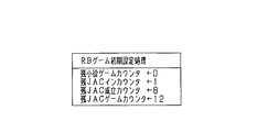
このボーナス図柄判定処理では、図19に示すように、まずステップS1001にてRB当選フラグがセットされているか否かを判定し、セットされているときにはステップS1002に進み、今回有効ライン上にRB図柄(例えば「BAR」図柄)が揃ったか否かを判定し、RB図柄が揃っていないときにはそのまま本処理を終了する。一方、今回有効ライン上にRB図柄が揃ったときには、ステップS1003においてRB当選フラグをリセットしRB設定フラグをセットしてボーナスゲームの1種であるRBゲームとし、図20に示すRBゲーム初期設定処理を実行して本処理を終了する。ステップS1001でRB当選フラグがセットされていないときには、ステップS1004にてBB当選フラグがセットされたか否かを判定し、セットされていないときにはそのまま本処理を終了する。BB当選フラグがセットされているときにはステップS1005に進み、今回有効ライン上にBB図柄(例えば図柄「7」)が揃ったか否かを判定し、BB図柄が揃っていないときにはそのまま本処理を終了する。一方、今回有効ライン上にBB図柄が揃ったときには、ステップS1006においてBB当選フラグをリセットしBB設定フラグをセットしてボーナスゲームの1種であるBBゲームとし、図21示すBBゲーム初期設定処理を実行して本処理を終了する。 In this bonus symbol determination process, as shown in FIG. 19, it is first determined in step S1001 whether or not the RB winning flag is set. If it is set, the process proceeds to step S1002, and the RB symbol is placed on the current effective line. It is determined whether or not (for example, “BAR” symbols) are aligned, and if the RB symbols are not aligned, this processing is terminated. On the other hand, when the RB symbols are aligned on the active line this time, in step S1003, the RB winning flag is reset and the RB setting flag is set to make an RB game which is one type of bonus game, and the RB game initial setting process shown in FIG. To finish this processing. If the RB winning flag is not set in step S1001, it is determined whether or not the BB winning flag is set in step S1004. If it is not set, the process is terminated. When the BB winning flag is set, the process proceeds to step S1005, where it is determined whether or not the BB symbol (for example, symbol “7”) is aligned on the current effective line, and when the BB symbol is not aligned, this processing is terminated. . On the other hand, when the BB symbols are aligned on the active line this time, in step S1006, the BB winning flag is reset and the BB setting flag is set to set the BB game as one type of bonus game, and the BB game initial setting process shown in FIG. Execute this to finish this process.
なお、図20,図21において、残小役ゲームカウンタは小役ゲームの残りゲーム数(残小役ゲーム数ともいう)を表し、残JACインカウンタはJACイン可能な残り回数(残JACイン回数ともいう)を表し、残JAC成立カウンタはJAC図柄が成立可能な残り回数(残JAC成立数ともいう)を表し、残JACゲームカウンタはJACゲームの残りゲーム数(残JACゲーム数ともいう)を表す。残小役ゲーム数や、残JACイン回数や、残JAC成立数、残JACゲーム数は、適宜、ゲーム数表示部36に表示される。ちなみに、役の抽選で小役またはリプレイに当選して小役当選フラグまたはリプレイ当選フラグがセットされたときには、そのゲームで小役図柄またはリプレイ図柄を有効ライン上に揃えられないとこれらの当選フラグはリセットされるが、役の抽選でRBまたはBBに当選してRB当選フラグまたはBB当選フラグがセットされたときには、そのゲームでRB図柄またはBB図柄を有効ライン上に揃えられなかったとしてもこれらの当選フラグは次回に持ち越される。なお、BB又はRB当選フラグを持ち越した次ゲームにおける抽選処理では、小役又はリプレイの当選可否に関する抽選は行われるが、BB又はRBに関する抽選は行われない。また、BB又はRB当選フラグを持ち越した状態で小役又はリプレイに当選した場合には、小役又はリプレイが優先して揃えられるようにスベリテーブルが格納される。
20 and 21, the remaining small role game counter represents the remaining number of small role games (also referred to as the remaining small role game number), and the remaining JAC in counter is the remaining number of remaining JAC in (remaining JAC in number). The remaining JAC establishment counter represents the remaining number of times that the JAC symbol can be established (also referred to as the number of remaining JAC formations), and the remaining JAC game counter represents the number of remaining JAC games (also referred to as the number of remaining JAC games). Represent. The number of remaining small role games, the number of remaining JAC ins, the number of remaining JACs established, and the number of remaining JAC games are displayed on the game
さて、図18に戻り、ステップS901で遊技状態がボーナスゲーム中のときには、ステップS903にてそのボーナスゲームがJACゲームか否かを判定する。JACゲームでないときにはBBゲームの小役ゲーム中であることを意味するため、ステップS904に進み、JAC図柄が有効ライン上に揃ったか否かを判定する。JAC図柄が有効ライン上に揃ったときには、ステップS905にてJACゲームを開始すると共に図21(b)のBBゲーム中JACゲーム初期設定処理を行い、本処理を終了する。一方、ステップS904でJAC図柄が有効ライン上に揃わなかったときには、小役ゲームが1ゲーム消化されたことになるため、ステップS906にて残小役ゲーム数を1ディクリメントし、ステップS907にてその残小役ゲーム数が0になったか否かを判定する。残小役ゲーム数が0でないときには本処理を終了し、0のときにはステップS908に進み、各種設定フラグやBB設定フラグや各種カウンタなどを適宜リセットしたりエンディング処理を行ったりする特別遊技状態終了処理を行い、本処理を終了する。 Now, referring back to FIG. 18, when the gaming state is a bonus game in step S901, it is determined in step S903 whether the bonus game is a JAC game. If it is not a JAC game, it means that the BB game is in the small role game, so the process proceeds to step S904, and it is determined whether or not the JAC symbols are aligned on the active line. When the JAC symbols are aligned on the active line, the JAC game is started in step S905 and the JAC game initial setting process during the BB game shown in FIG. 21B is performed, and this process ends. On the other hand, when the JAC symbols are not aligned on the active line in step S904, the small role game has been consumed, so in step S906 the remaining small role game number is decremented by 1, and in step S907. It is determined whether or not the number of remaining small role games has become zero. When the remaining small role game number is not 0, the present process is terminated. When the remaining small role game number is 0, the process proceeds to step S908, and a special game state end process for appropriately resetting various setting flags, BB setting flags, various counters, etc. or performing an ending process. To end this process.
ステップS903で遊技状態がJACゲームであるときには、ステップS909に進みJAC図柄が有効ライン上に揃ったか否かを判定し、JAC図柄が有効ライン上に揃ったときにはステップS910にて残JAC成立数を1ディクリメントする。その後、或いはステップS909でJAC図柄が有効ライン上に揃わなかったときには、JACゲームを1つ消化したことになるため、ステップS911にて残JACゲーム数を1ディクリメントする。続いて、ステップS912では残JAC成立数か残JACゲーム数のいずれかが0になったか否かを判定し、いずれも0になっていないとき、つまりJAC図柄がまだ8回成立しておらずJACゲームも12回消化されていないときには、そのまま本処理を終了する。一方、いずれかが0になっていたとき、つまりJAC図柄が8回成立したかJACゲームが12回消化されたときには、JACインが1回消化されたことになるためステップS913にて残JACイン回数を1ディクリメントし、続くステップS914にてその残JACイン回数が0か否かを判定する。0のときには先に述べたステップS908の特別遊技状態終了処理を行い、本処理を終了する。ちなみに、当該ボーナスゲームがRBボーナスである場合には、当初の残JACイン回数が1(図20参照)であるからステップS913で0になり、ステップS914で必ず肯定判定され、ステップS908の特別遊技状態終了処理にてRB設定フラグがリセットされる。 When the gaming state is a JAC game in step S903, the process proceeds to step S909 to determine whether or not the JAC symbols are aligned on the active line. When the JAC symbols are aligned on the active line, the number of remaining JACs established is determined in step S910. Decrement by one. After that, or when the JAC symbols are not aligned on the active line in step S909, one JAC game has been consumed, so the number of remaining JAC games is decremented by 1 in step S911. Subsequently, in step S912, it is determined whether or not any of the remaining number of JACs or the number of remaining JAC games has become 0. If neither is 0, that is, the JAC symbol has not yet been established 8 times. If the JAC game has not been digested 12 times, the process is terminated as it is. On the other hand, if any of them is 0, that is, if the JAC symbol is established 8 times or the JAC game is digested 12 times, the JAC in is digested once, so in step S913 the remaining JAC in The number of times is decremented by 1, and in the subsequent step S914, it is determined whether or not the number of remaining JAC in is zero. When it is 0, the special gaming state termination process of step S908 described above is performed, and this process is terminated. Incidentally, if the bonus game is an RB bonus, the initial remaining JAC in number is 1 (see FIG. 20), so it becomes 0 in step S913, and a positive determination is always made in step S914, and the special game in step S908. The RB setting flag is reset in the state end process.
一方、ステップS914で残JACイン回数がゼロでないとき、つまりBBゲームでJACインが3回消化されていないときには、ステップS915においてJACゲーム設定フラグをリセットするJACゲーム終了処理を行ったあと、今回JACインしたときに小役ゲームを1ゲーム消化しているためステップS906にて残小役ゲーム数を1ディクリメントし、続いてステップS907にてその残小役ゲーム数が0になったか否かを判定し、残小役ゲーム数が0のときには先に述べたステップS908の特別遊技状態終了処理を行い、本処理を終了する。一方、残小役ゲーム数が0でないときにはBBボーナスにおける小役ゲームが30回に達しておらず且つJACインも3回に達していないため、本処理を終了する。 On the other hand, when the number of remaining JAC ins is not zero in step S914, that is, when the JAC in has not been digested three times in the BB game, after performing the JAC game end processing for resetting the JAC game setting flag in step S915, When the player enters the game, one of the small role games is digested, so the number of remaining small role games is decremented by 1 in step S906, and then whether or not the remaining small role game number has become 0 in step S907. If it is determined that the number of remaining small role games is 0, the special game state ending process in step S908 described above is performed, and this process is ended. On the other hand, when the remaining small-combination game number is not 0, the small-combination game in the BB bonus has not reached 30 times and the JAC in has not reached 3 times.
以上詳述したように本実施の形態によれば、第1クレジット投入スイッチ77がスタートレバー71の上部に被せるようにして設けられているため、遊技者は第1クレジット投入スイッチ77による仮想メダルの投入と、それに続くスタートレバー71による各リール42L,42M,42Rの回転始動とを、片手を一度振り下ろす動作だけで行うことが可能となる。このため、遊技者は遊技を開始する際に、仮想メダルを投入するための動作と、スタートレバー71を操作するための動作という各別の計2回の動作を行う必要がなくなる。これにより、遊技開始時に必要な手の動きが簡略化され、手の疲れの要因となる余分な動作を省くことができる。その結果、数時間という長時間にわたって遊技を行うような遊技者であっても、手の疲労による遊技継続への気力を損なわせてしまうことを回避できる。
As described above in detail, according to the present embodiment, the first
なお、上述した記載内容に限定されず、例えば次のように実施してもよい。 In addition, it is not limited to the description content mentioned above, For example, you may implement as follows.
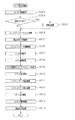
(a)上記実施の形態では、第1クレジット投入スイッチ77をスタートレバー71とは別に設けたが、スタートレバー71にこの第1クレジット投入スイッチ77の機能をもたせることも可能である。この場合、考えられる一つの構成として、スイッチの操作量によって仮想メダルの投入操作と各リール42L,42M,42Rの回転を始動させる操作とを区別する構成が考えられる。例えば、図22に示すように、斜め上を向いた状態(A)を初期状態とし、スタートレバー71を一定量操作した状態(B)でまず仮想メダルの投入が行われ、さらに一定量操作した状態(C)で各リール42L,42M,42Rの回転が始動されるように構成する。このような構成によっても、仮想メダルの投入と、それに続く各リール42L,42M,42Rの回転始動とを、片手を一度振り下ろしてスタートレバー71押し下げる動作だけで行うことが可能となる。この他、スタートレバー71の代わりにボタン状のスイッチを用いた場合でも、同様の操作が行われるように構成することも可能である。
(A) In the above embodiment, the first
(b)上記実施の形態では、スタートレバー71を従来どおり、レバー部71aの先端に球体71bを設けた構成とし、第1クレジット投入スイッチ77をスタートレバー71に被せるように設けたが、スタートレバー71及び第1クレジット投入スイッチ77の構成はこれに限られるものではない。例えば、図23に示すように、従来のスタートレバー71の形状を2つに分割した構成とし、上側の分割片を第1クレジット投入スイッチ77、下側の分割片をスタートレバー71とする構成も採用できる。この場合、スタートレバー71と、第1クレジット投入スイッチ77とを、あたかも一つのスタートレバー71であるかのように構成することができる。このため、スタートレバー71及び第1クレジット投入スイッチ77の設置スペースを小さくすることができる。
(B) In the above embodiment, the
(c)図24に示すように、第1クレジット投入スイッチ77の手前側先端部をスタートレバー71の手前側先端部よりも後退させる構成としても良い。スロットマシン前面を基準として第1クレジット投入スイッチ77先端部までの距離と、スタートレバー71先端部までの距離とを比べると後者の方が長くなる。そのため、図のA位置で操作を行えば、第1クレジット投入スイッチ77及びスタートレバー71の連続操作が可能となり、図のB位置で操作を行えば、スタートレバー71のみの操作が可能となる。これにより、第1クレジット投入スイッチ77とは異なる別のクレジット投入スイッチ(入力手段)を操作した後、スタートレバー71のみの操作(第1クレジット投入スイッチ77を伴わない操作)が可能となる。
(C) As shown in FIG. 24, the front end portion of the first
(d)上記実施の形態では、仮想メダルの投入は、第1クレジット投入スイッチ77又は第2クレジット投入スイッチ79の操作に限られているが、これ以外の構成を採用することも可能である。例えば、従来から知られている構成、すなわち、仮想メダルを1枚投入、2枚投入、3枚投入するための各別の通常投入スイッチを設けた構成において、さらに本実施形態の第1クレジット投入スイッチ77を設けた構成とする。そして、第1クレジット投入スイッチ77による操作の有効・無効を切り換える入力切換スイッチ(入力切換手段)を設ける。この場合、第1クレジット投入スイッチ77は第1入力手段を構成し、前記各通常投入スイッチは第2入力手段を構成する。かかる構成によれば、従来からの構成を使用することができるため、汎用性が高まる。また、従来通りの操作による遊技も併せて行うことができるという利点から、従来通りの操作を望む遊技者のニーズにも対応することができる。なお、前記入力切換スイッチ自身又はその周辺には第1クレジット投入スイッチ77による操作が有効な状態か無効な状態かを表示して現状を遊技者に教示すべく、ランプ等の表示手段を設けてもよい。
(D) In the above embodiment, the insertion of the virtual medal is limited to the operation of the first
(e)上記実施の形態では、スタートレバー71及び第1クレジット投入スイッチ77は下方向へ手で押し操作するように構成したが、逆に上方向へ手で押し上げ操作するように構成したり、横方向、斜め方向へ操作するように構成したりすることも可能である。かかる構成によっても、手の動きを簡略化できるという上記実施の形態と同様の作用効果が得られる。
(E) In the above-described embodiment, the
(f)上記実施の形態では、可変表示手段を円筒状の各リール42L,42M,42Rを備えたリールユニット41によって構成したが、扁平状のリールを備えたリールユニット、液晶表示器などによって構成することもできる。また、この液晶表示器はリールを液晶表示する構成としてもよい。
(F) In the above embodiment, the variable display means is configured by the
(g)上記実施の形態では、可変表示手段を構成するリールユニット41は左リール42L,中リール42M,右リール42Rの3つのリールを備えているが、リールの数は4つ以上設けてもよい。また、スロットマシン10に設けられるリールユニット41自体、1つに限定されず、上下又は左右等に2つ以上設けてもよい。
(G) In the above embodiment, the
(h)上記実施の形態では、仮想メダルの投入は、1枚投入、2枚投入、3枚投入が可能となっているが、3枚投入、すなわちマックスベットによる遊技のみが可能な構成としてもよい。 (H) In the above embodiment, virtual medals can be inserted in one, two, or three. However, a configuration in which only three games can be inserted, that is, a game with a maximum bet can be used. Good.
(i)上記実施の形態では、遊技者は、第1クレジット投入スイッチ77の操作により投入される仮想メダルの枚数が何枚であるか(1枚か3枚)を、ランプの点灯によって投入数切換スイッチ78に表示される「1BET」又は「MAXBET」という文字から判断することになる。かかる判断手段としては、この構成に限定されず、例えば「1BET」又は「MAXBET」という文字が表示される表示部を第1クレジット投入スイッチ77に設けたり、それら各種スイッチとは別個に設けたりしてもよい。
(I) In the above embodiment, the player determines how many virtual medals are inserted by operating the first credit insertion switch 77 (one or three) by turning on the lamp. The determination is made from the characters “1 BET” or “MAX BET” displayed on the
(j)上記実施の形態では、2枚ベット用の第2クレジット投入スイッチ79を操作した場合でも、投入数切換スイッチ78がオフ状態であれば、スタートレバー71の操作時に操作される第1クレジット投入スイッチ77の3枚ベットが優先されてしまうが、それを避けるような構成を採用することも可能である。すなわち、スタートレバー71を下から上方向への操作が可能となるように構成する。この構成では、第2クレジット投入スイッチ79を操作した後、上方向へスタートレバー71を押し上げ操作すれば、所望した2枚ベットの状態で遊技を開始することができる。
(J) In the above embodiment, even when the second
(k)上記実施の形態では、回胴式遊技機としてスロットマシンに適用した場合について説明したが、この他、スロットマシンとパチンコ機とを融合したタイプの遊技機、すなわち、遊技媒体としてメダルの代わりに遊技球を用いた球使用ベルト式遊技機等にも適用できる。 (K) In the above embodiment, the case where the slot machine is applied to a slot machine has been described. Instead, it can also be applied to a belt-type game machine using a game ball.
10…遊技機としてのスロットマシン、11…筐体、12…前面扉、15…補助表示部、42…回胴を構成するリール、61…駆動手段としてのステッピングモータ、71…始動操作手段としてのスタートレバー、72〜74…停止操作手段としてのストップスイッチ、77…入力手段又はベットレバーとしての第1クレジット投入スイッチ、78…ベット機能切換手段としての投入数切換スイッチ、111…サブ制御手段としての表示制御装置、131…メイン制御手段としての主制御装置、151…制御手段としてのCPU、152,153…記憶手段としてのROM,RAM、161…電源装置。
DESCRIPTION OF
Claims (1)
絵柄を可変表示する可変表示手段と、
記憶管理された遊技媒体から所定数の遊技媒体を投入するための入力手段と、
前記可変表示手段を始動させる始動操作手段と
を備えた遊技機であって、
前記入力手段及び前記始動操作手段を、遊技者による片手を使った一回の動作で操作可能に構成した遊技機。 It has a virtual storage function for storing and managing game media as virtual game media,
Variable display means for variably displaying the pattern;
An input means for inputting a predetermined number of game media from the storage-managed game media;
A gaming machine comprising start operation means for starting the variable display means,
A gaming machine configured such that the input means and the starting operation means can be operated by a single operation by a player using one hand.
Priority Applications (1)
| Application Number | Priority Date | Filing Date | Title |
|---|---|---|---|
| JP2003397654A JP2005152436A (en) | 2003-11-27 | 2003-11-27 | Game machine |
Applications Claiming Priority (1)
| Application Number | Priority Date | Filing Date | Title |
|---|---|---|---|
| JP2003397654A JP2005152436A (en) | 2003-11-27 | 2003-11-27 | Game machine |
Publications (2)
| Publication Number | Publication Date |
|---|---|
| JP2005152436A true JP2005152436A (en) | 2005-06-16 |
| JP2005152436A5 JP2005152436A5 (en) | 2007-01-18 |
Family
ID=34722752
Family Applications (1)
| Application Number | Title | Priority Date | Filing Date |
|---|---|---|---|
| JP2003397654A Withdrawn JP2005152436A (en) | 2003-11-27 | 2003-11-27 | Game machine |
Country Status (1)
| Country | Link |
|---|---|
| JP (1) | JP2005152436A (en) |
Cited By (4)
| Publication number | Priority date | Publication date | Assignee | Title |
|---|---|---|---|---|
| JP2007000414A (en) * | 2005-06-24 | 2007-01-11 | Samii Kk | Slot machine |
| JP2007190143A (en) * | 2006-01-18 | 2007-08-02 | Samii Kk | Game machine |
| KR100830307B1 (en) | 2006-07-14 | 2008-05-19 | 가부시키가이샤 소피아 | Game machine |
| JP2012170778A (en) * | 2011-02-24 | 2012-09-10 | Takao Co Ltd | Reel-type game machine |
-
2003
- 2003-11-27 JP JP2003397654A patent/JP2005152436A/en not_active Withdrawn
Cited By (4)
| Publication number | Priority date | Publication date | Assignee | Title |
|---|---|---|---|---|
| JP2007000414A (en) * | 2005-06-24 | 2007-01-11 | Samii Kk | Slot machine |
| JP2007190143A (en) * | 2006-01-18 | 2007-08-02 | Samii Kk | Game machine |
| KR100830307B1 (en) | 2006-07-14 | 2008-05-19 | 가부시키가이샤 소피아 | Game machine |
| JP2012170778A (en) * | 2011-02-24 | 2012-09-10 | Takao Co Ltd | Reel-type game machine |
Similar Documents
| Publication | Publication Date | Title |
|---|---|---|
| JP2018027368A (en) | Game machine | |
| JP4876404B2 (en) | Game machine | |
| JP5121113B2 (en) | Game machine | |
| JP2005118170A (en) | Game machine | |
| JP2005296081A (en) | Game machine | |
| JP2005152436A (en) | Game machine | |
| JP2006230556A (en) | Game machine | |
| JP5121112B2 (en) | Game machine | |
| JP4826112B2 (en) | Game machine | |
| JP2005288028A (en) | Game machine | |
| JP4600587B2 (en) | Game machine | |
| JP6451791B2 (en) | Game machine | |
| JP2005118171A (en) | Game machine | |
| JP2005211604A (en) | Game machine | |
| JP2006051274A (en) | Game machine | |
| JP2005312499A5 (en) | ||
| JP5435078B2 (en) | Game machine | |
| JP5126264B2 (en) | Game machine | |
| JP4600591B2 (en) | Game machine | |
| JP2014100518A (en) | Game machine | |
| JP5045825B2 (en) | Game machine | |
| JP4691956B2 (en) | Game machine | |
| JP2018138243A (en) | Game machine | |
| JP2010279792A (en) | Game machine | |
| JP2018043088A (en) | Game machine |
Legal Events
| Date | Code | Title | Description |
|---|---|---|---|
| A521 | Written amendment |
Free format text: JAPANESE INTERMEDIATE CODE: A523 Effective date: 20061127 |
|
| A621 | Written request for application examination |
Free format text: JAPANESE INTERMEDIATE CODE: A621 Effective date: 20061127 |
|
| A761 | Written withdrawal of application |
Free format text: JAPANESE INTERMEDIATE CODE: A761 Effective date: 20091112 |