JP2005122503A - Cooling apparatus and electronic equipment incorporating the same - Google Patents
Cooling apparatus and electronic equipment incorporating the same Download PDFInfo
- Publication number
- JP2005122503A JP2005122503A JP2003357245A JP2003357245A JP2005122503A JP 2005122503 A JP2005122503 A JP 2005122503A JP 2003357245 A JP2003357245 A JP 2003357245A JP 2003357245 A JP2003357245 A JP 2003357245A JP 2005122503 A JP2005122503 A JP 2005122503A
- Authority
- JP
- Japan
- Prior art keywords
- liquid
- cooling
- radiator
- height
- cooling liquid
- Prior art date
- Legal status (The legal status is an assumption and is not a legal conclusion. Google has not performed a legal analysis and makes no representation as to the accuracy of the status listed.)
- Pending
Links
Images


Classifications
-
- F—MECHANICAL ENGINEERING; LIGHTING; HEATING; WEAPONS; BLASTING
- F28—HEAT EXCHANGE IN GENERAL
- F28F—DETAILS OF HEAT-EXCHANGE AND HEAT-TRANSFER APPARATUS, OF GENERAL APPLICATION
- F28F9/00—Casings; Header boxes; Auxiliary supports for elements; Auxiliary members within casings
- F28F9/26—Arrangements for connecting different sections of heat-exchange elements, e.g. of radiators
- F28F9/262—Arrangements for connecting different sections of heat-exchange elements, e.g. of radiators for radiators
-
- G—PHYSICS
- G06—COMPUTING; CALCULATING OR COUNTING
- G06F—ELECTRIC DIGITAL DATA PROCESSING
- G06F1/00—Details not covered by groups G06F3/00 - G06F13/00 and G06F21/00
- G06F1/16—Constructional details or arrangements
- G06F1/20—Cooling means
-
- F—MECHANICAL ENGINEERING; LIGHTING; HEATING; WEAPONS; BLASTING
- F28—HEAT EXCHANGE IN GENERAL
- F28D—HEAT-EXCHANGE APPARATUS, NOT PROVIDED FOR IN ANOTHER SUBCLASS, IN WHICH THE HEAT-EXCHANGE MEDIA DO NOT COME INTO DIRECT CONTACT
- F28D1/00—Heat-exchange apparatus having stationary conduit assemblies for one heat-exchange medium only, the media being in contact with different sides of the conduit wall, in which the other heat-exchange medium is a large body of fluid, e.g. domestic or motor car radiators
- F28D1/02—Heat-exchange apparatus having stationary conduit assemblies for one heat-exchange medium only, the media being in contact with different sides of the conduit wall, in which the other heat-exchange medium is a large body of fluid, e.g. domestic or motor car radiators with heat-exchange conduits immersed in the body of fluid
- F28D1/04—Heat-exchange apparatus having stationary conduit assemblies for one heat-exchange medium only, the media being in contact with different sides of the conduit wall, in which the other heat-exchange medium is a large body of fluid, e.g. domestic or motor car radiators with heat-exchange conduits immersed in the body of fluid with tubular conduits
- F28D1/053—Heat-exchange apparatus having stationary conduit assemblies for one heat-exchange medium only, the media being in contact with different sides of the conduit wall, in which the other heat-exchange medium is a large body of fluid, e.g. domestic or motor car radiators with heat-exchange conduits immersed in the body of fluid with tubular conduits the conduits being straight
- F28D1/0535—Heat-exchange apparatus having stationary conduit assemblies for one heat-exchange medium only, the media being in contact with different sides of the conduit wall, in which the other heat-exchange medium is a large body of fluid, e.g. domestic or motor car radiators with heat-exchange conduits immersed in the body of fluid with tubular conduits the conduits being straight the conduits having a non-circular cross-section
- F28D1/05366—Assemblies of conduits connected to common headers, e.g. core type radiators
-
- F—MECHANICAL ENGINEERING; LIGHTING; HEATING; WEAPONS; BLASTING
- F28—HEAT EXCHANGE IN GENERAL
- F28D—HEAT-EXCHANGE APPARATUS, NOT PROVIDED FOR IN ANOTHER SUBCLASS, IN WHICH THE HEAT-EXCHANGE MEDIA DO NOT COME INTO DIRECT CONTACT
- F28D15/00—Heat-exchange apparatus with the intermediate heat-transfer medium in closed tubes passing into or through the conduit walls ; Heat-exchange apparatus employing intermediate heat-transfer medium or bodies
-
- H—ELECTRICITY
- H01—ELECTRIC ELEMENTS
- H01L—SEMICONDUCTOR DEVICES NOT COVERED BY CLASS H10
- H01L23/00—Details of semiconductor or other solid state devices
- H01L23/34—Arrangements for cooling, heating, ventilating or temperature compensation ; Temperature sensing arrangements
- H01L23/46—Arrangements for cooling, heating, ventilating or temperature compensation ; Temperature sensing arrangements involving the transfer of heat by flowing fluids
- H01L23/473—Arrangements for cooling, heating, ventilating or temperature compensation ; Temperature sensing arrangements involving the transfer of heat by flowing fluids by flowing liquids
-
- F—MECHANICAL ENGINEERING; LIGHTING; HEATING; WEAPONS; BLASTING
- F28—HEAT EXCHANGE IN GENERAL
- F28D—HEAT-EXCHANGE APPARATUS, NOT PROVIDED FOR IN ANOTHER SUBCLASS, IN WHICH THE HEAT-EXCHANGE MEDIA DO NOT COME INTO DIRECT CONTACT
- F28D21/00—Heat-exchange apparatus not covered by any of the groups F28D1/00 - F28D20/00
- F28D2021/0019—Other heat exchangers for particular applications; Heat exchange systems not otherwise provided for
- F28D2021/0028—Other heat exchangers for particular applications; Heat exchange systems not otherwise provided for for cooling heat generating elements, e.g. for cooling electronic components or electric devices
- F28D2021/0031—Radiators for recooling a coolant of cooling systems
-
- H—ELECTRICITY
- H01—ELECTRIC ELEMENTS
- H01L—SEMICONDUCTOR DEVICES NOT COVERED BY CLASS H10
- H01L2924/00—Indexing scheme for arrangements or methods for connecting or disconnecting semiconductor or solid-state bodies as covered by H01L24/00
- H01L2924/0001—Technical content checked by a classifier
- H01L2924/0002—Not covered by any one of groups H01L24/00, H01L24/00 and H01L2224/00
Landscapes
- Engineering & Computer Science (AREA)
- Physics & Mathematics (AREA)
- General Engineering & Computer Science (AREA)
- Mechanical Engineering (AREA)
- Thermal Sciences (AREA)
- General Physics & Mathematics (AREA)
- Condensed Matter Physics & Semiconductors (AREA)
- Computer Hardware Design (AREA)
- Microelectronics & Electronic Packaging (AREA)
- Power Engineering (AREA)
- Theoretical Computer Science (AREA)
- Human Computer Interaction (AREA)
- Cooling Or The Like Of Electrical Apparatus (AREA)
- Heat-Exchange Devices With Radiators And Conduit Assemblies (AREA)
Abstract
Description
本発明は、電子計算機等を含めた電子機器に係り、特に、ラックマウント方式のサーバ等の情報処理装置の冷却に適用することで、装置の高性能化や小型化を可能とする液冷装置に関するものである。 The present invention relates to an electronic apparatus including an electronic computer or the like, and in particular, a liquid cooling apparatus that enables high performance and downsizing of the apparatus by being applied to cooling of an information processing apparatus such as a rack mount server. It is about.
サーバ等の情報処理装置のシステム構成・収納および設置において、ラックマウント方式が主流となっている。ラックマウント方式とは、装置を機能単位別に分割して収納するラックと呼ばれる筐体を、特定の規格に基づき形成されたキャビネットと呼ばれるユニットシャーシに段積み搭載する方式である。ラックマウント方式では、装置単位でのハードウェア開発が可能にあると同時に、各装置の選択・配置を自由に行え、システム構成の柔軟性・拡張性に優れ、さらにシステム全体の占有面積も縮小できるという利点がある。 In the system configuration / storage and installation of information processing apparatuses such as servers, the rack mount method has become the mainstream. The rack mount method is a method in which a housing called a rack that divides and stores devices into functional units is stacked and mounted on a unit chassis called a cabinet formed based on a specific standard. The rack-mount method enables hardware development on a device-by-device basis, allows you to freely select and place each device, excels in system configuration flexibility and expandability, and reduces the overall system footprint There is an advantage.
特に、ラックマウント方式のサーバでは、IEC規格(International Electrical Commission)/EIA規格(The Electrical Industries Association)により規定された19インチ幅のキャビネットが主流となっており、装置を搭載するための支柱の左右間口寸法を451mm、搭載における高さ寸法を1U(1EIA)=44.45mmという単位で規定している。そのため、ラックマウント方式のサーバや、これと組み合わせて情報処理システムを構築するネットワーク機器、ディスクアレイ装置、あるいは無停電電源装置の筐体の幅は、19インチ幅のキャビネットに搭載可能であるように規定されない幅で構成される。また、筐体の高さについては、キャビネット内に筐体が密に段積みできるように、1Uを単位高さとした高さ、例えば3U(1Uの3倍の高さ)、5U(1Uの5倍の高さ)といった高さで構成される。 In particular, rack mount servers are mainly 19-inch cabinets defined by the IEC standard (International Electrical Commission) / EIA standard (The Electrical Industries Association). The frontage dimension is specified in units of 451 mm, and the height dimension in mounting is 1U (1EIA) = 44.45 mm. Therefore, the width of the rack of the rack mount server or the network equipment, disk array device, or uninterruptible power supply that constructs the information processing system in combination with this can be mounted in a 19-inch cabinet. Consists of unspecified width. In addition, the height of the housing is set so that the housings are densely stacked in the cabinet, for example, 1U is a unit height, for example, 3U (three times the height of 1U), 5U (1U of 5 Double height).
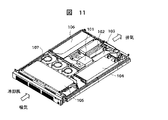
このラックマウント方式のサーバの筐体の実装例を図11に示す。図11の筐体は、1U(約45mm)の高さをもち、CPU(101)やメモリ102を実装したメインボード103、専用の冷却ファンを内蔵する電源ユニット104、HDDやCD‐ROM等のストレージ105、拡張ボード106から構成される。さらに、主にCPUを冷却するために、筐体の中央部に冷却ファン107を配置し、ファンの冷却風をCPUのヒートシンクに吹き付けて冷却をおこなっている。
FIG. 11 shows an example of mounting of the rack mount server chassis. 11 has a height of 1U (about 45 mm), a
図11の従来のラックマウント方式のサーバの筐体では、筐体の前面から吸気し、冷却風は筐体後面から周囲に排気される。このとき、冷却ファン107による冷却風の流れにより、モジュールの前部に配置されたストレージやCPU以外のメモリ102等のメインボード103に実装されている電子部品(図示せず)も冷却される。このようなラックマウント方式のサーバの冷却技術として、筐体上面の前面寄りの部分に通気口を設け、これをキャビネットに実装する際に、この通気口を塞がないように、上部に積まれる装置筐体をずらして配置する構成が、特許文献1に開示されている。
In the case of the conventional rack mount server shown in FIG. 11, the air is sucked from the front of the case, and the cooling air is exhausted from the rear of the case to the surroundings. At this time, electronic components (not shown) mounted on the
また、ラックマウント方式の電子機器を冷却する手段として、キャビネット内に液冷システムを有し、キャビネットを構成する複数の柱内に液冷用の冷媒流路を設け、少なくとも1つの柱から冷却媒体をキャビネットに積まれる筐体に供給して筐体内で発生した熱を吸収し、熱を吸収した冷媒を残る柱のうちの1つの柱へ流し出して冷却する冷却方式が、特許文献2に開示されている。
Further, as means for cooling the rack-mount type electronic device, a liquid cooling system is provided in the cabinet, a coolant flow path for liquid cooling is provided in a plurality of pillars constituting the cabinet, and a cooling medium is provided from at least one pillar.
特許文献3には、複数の電子部品が筐体内に収納されてなる電子機器の冷却方法において、発熱電子部品の熱を受熱部材により受け、該受熱部材に備えられた流路に冷却液を流して前記受熱部材を冷却し、該受熱部材に流した冷却液を前記電子機器の筐体に熱的に接続された放熱部材の流路に流して放熱する電子機器の冷却方法が記載されている。
また、特許文献4には液冷システムを内蔵させた小型電子計算機が記載されている。
In
特許文献1に開示された通り、近年、電子装置の高性能化と高密度実装化が進み、装置筐体内に実装される部品、特にCPUの冷却が困難となっている。これを克服する方法として、特許文献2に開示された通り、少なくともキャビネット単位で閉じる系で構成する液冷装置を導入することが考えられる。
As disclosed in
図11で示した通り、従来のサーバ等の情報処理装置に採用している冷却システムは、発熱部品に直接取り付けるヒートシンクと、このヒートシンクに冷却風を送風する冷却ファンの2つで構成される。これに対して液冷装置(システム)は、冷却ファンに加えて冷却液を循環するポンプ、ヒートシンクの代わりに吸熱用の液冷ジャケットと放熱用のラジエータ、さらに各デバイスを接続する冷却液配管が必要となり、さらに使用条件に応じてリザーバタンク等を設ける必要があることから、部品点数が大幅に増加するため、液冷装置を電子機器の冷却装置として広く普及するためには、コスト低減が大きな課題である。 As shown in FIG. 11, a cooling system employed in a conventional information processing apparatus such as a server is composed of a heat sink directly attached to a heat-generating component and a cooling fan that blows cooling air to the heat sink. On the other hand, a liquid cooling system (system) includes a pump that circulates cooling liquid in addition to a cooling fan, a liquid cooling jacket for heat absorption instead of a heat sink, a radiator for heat dissipation, and a cooling liquid pipe that connects each device. In addition, since it is necessary to provide a reservoir tank or the like according to the use conditions, the number of parts is greatly increased. Therefore, in order to widely spread the liquid cooling device as a cooling device for electronic devices, cost reduction is large. It is a problem.
また、サーバ等の情報処理装置のシステム構成・収納および設置においては、ラックマウント方式が主流となっており、その筐体大きさはキャビネットに搭載するための規格に応じて決定されている。高さ寸法については基準高さとなる1U(1EIA)=44.45mmの倍数で規定しており、最小で1U高さから、最大では例えば5U高さまで、数種類の筐体大きさがあるため、これらの装置に液冷装置を適用する場合、それぞれの筐体大きさに応じて、より高い冷却性能を引き出せる液冷装置を構成することが望まれる。 Further, in the system configuration / storage and installation of an information processing apparatus such as a server, the rack mount method is the mainstream, and the size of the casing is determined according to the standard for mounting in the cabinet. The height dimension is defined by a multiple of 1U (1EIA) = 44.45mm, which is the reference height, and there are several types of housing sizes from a minimum of 1U to a maximum of 5U, for example. When the liquid cooling device is applied to this device, it is desired to configure a liquid cooling device that can draw out higher cooling performance in accordance with the size of each case.
本発明の目的は、液冷装置の低コスト化を実現するとともに、多様な大きさをもつ電子装置筐体に対して、高密度に実装可能な液冷装置を提供することにある。 An object of the present invention is to provide a liquid cooling device that can be mounted at high density on an electronic device housing having various sizes while realizing cost reduction of the liquid cooling device.
上記目的を達成するために次に示す液冷装置およびこの装置を内蔵した電子装置を提供する。
本発明は、冷却液を循環するポンプと、発熱部からの発生熱を冷却液に吸熱する液冷ジャケットと、冷却液の蓄熱を外気に放熱するラジエータとを備える電子機器の液冷却装置において、前記ラジエータは、高さが44mm以下で、35mm以上とされた独立体として構成され、ヘッダに少なくとも2個以上の流入口側コネクタ、2個以上の流出口側コネクタを備えた単体ラジエータが、複数個高さ方向および横方向に組み立てられるものであって、高さ方向および横方向のいずれかの方向に組み立てられて構成される液冷装置を提供する。
In order to achieve the above object, the following liquid cooling apparatus and an electronic apparatus incorporating the apparatus are provided.
The present invention relates to a liquid cooling apparatus for an electronic device comprising a pump that circulates a cooling liquid, a liquid cooling jacket that absorbs heat generated from a heat generating part into the cooling liquid, and a radiator that radiates heat stored in the cooling liquid to the outside air. The radiator is configured as an independent body having a height of 44 mm or less and 35 mm or more, and a plurality of unit radiators having at least two or more inlet-side connectors and two or more outlet-side connectors in a header. Provided is a liquid cooling device that is assembled in the height direction and the horizontal direction, and is assembled in either the height direction or the horizontal direction.
および本発明は、冷却液を循環するポンプと、発熱部からの発生熱を冷却液に吸熱する液冷ジャケットと、冷却液の蓄熱を外気に放熱するラジエータからなる液冷装置をキャビネット内に収納する電子機器において、前記液冷装置を構成する前記ラジエータは、高さが44mm以下で、35mm以上とされた独立体として構成され、ヘッダに少なくとも2個以上の流入口側コネクタ、2個以上の流出口側コネクタを備えた単体ラジエータが、複数個高さ方向および横方向に組み立てられるものであって、高さ方向および横方向のいずれかの方向に組み立てられて構成される電子機器を提供する。
上述の記載において、前記横方向は、通風方向および通風方向に対して直角方向のいずれかの方向を指す。
And a liquid cooling device comprising a pump for circulating the cooling liquid, a liquid cooling jacket for absorbing heat generated from the heat generating portion into the cooling liquid, and a radiator for radiating the heat stored in the cooling liquid to the outside air. In the electronic device, the radiator constituting the liquid cooling device is configured as an independent body having a height of 44 mm or less and 35 mm or more, and at least two or more inlet-side connectors and two or more headers on the header. Provided is an electronic device in which a plurality of unit radiators having an outlet-side connector are assembled in the height direction and the horizontal direction, and are assembled in either the height direction or the horizontal direction. .
In the above description, the lateral direction refers to either the ventilation direction or a direction perpendicular to the ventilation direction.
本発明によれば、液冷装置の主要デバイスである単体ラジエータの種類を独立構造の1種類として、これを組み合わせてそれぞれの筐体高さに応じてより広い通風断面積を確保可能な液冷装置を構成することが可能となる。そのため、液冷装置の高い冷却性能を損なうことなく、単一種類のラジエータの量産効果によってラジエータの低コスト化を実現することができる。 According to the present invention, the type of a single radiator, which is the main device of the liquid cooling device, is one type of independent structure, which can be combined to ensure a wider ventilation cross-sectional area according to the height of each casing. Can be configured. Therefore, the cost of the radiator can be reduced by the mass production effect of a single type of radiator without impairing the high cooling performance of the liquid cooling device.
本発明の液冷却装置は、冷却液を循環するポンプと、発熱部からの発生熱を冷却液に吸熱する液冷ジャケットと、冷却液の蓄熱を外気に放熱するラジエータとを備える電子機器に使用される。
前記ラジエータは、前記冷却液を通す扁平状の管を複数有し、複数の管の管にフィンを配設、固着して独立した1つのラジエータコアが構成され、該ラジエータコアの両端部がそれぞれヘッダに接合されて、該ヘッダから前記管に冷却液が流れるようにして単体ラジエータが構成される。
The liquid cooling device of the present invention is used in an electronic device including a pump that circulates the cooling liquid, a liquid cooling jacket that absorbs heat generated from the heat generating part into the cooling liquid, and a radiator that radiates heat storage of the cooling liquid to the outside air. Is done.
The radiator has a plurality of flat tubes through which the cooling liquid passes, and fins are disposed on the tubes of the plurality of tubes and fixed to form an independent radiator core, and both ends of the radiator core are respectively A single unit radiator is configured such that the coolant flows from the header to the pipe by being joined to the header.
そして、高さが44mm以下で、35mm以上、望ましくは40mm以下とで36mm以内とされた独立体として構成され、ヘッダに少なくとも2個以上の流入口側コネクタ、2個以上の流出口側コネクタを備えた単体ラジエータが、複数個高さ方向および横方向に組み立てられるものであって、高さ方向および横方向のいずれかの方向に組み立てられて構成される。 The height is 44 mm or less, 35 mm or more, preferably 40 mm or less, and is configured as an independent body within 36 mm. At least two inlet-side connectors and two or more outlet-side connectors are provided on the header. A plurality of the single radiators provided are assembled in the height direction and the horizontal direction, and are assembled in either the height direction or the horizontal direction.
以下、本発明の実施例1の形態を、図面を参照しながら詳細に説明する。
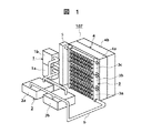
まず、本発明の第1実施形態として、筐体高さが3U(約133mm)で2CPU構成のサーバに実装する液冷装置の概要を示す。図1は本液冷装置107の概要を示す図である。図2は本液冷装置の模式図ある。図3は本液冷装置107を搭載するラックマウント方式のサーバのラック筐体の概要を示す図である。
Hereinafter, the form of Example 1 of this invention is demonstrated in detail, referring drawings.
First, as a first embodiment of the present invention, an outline of a liquid cooling device that is mounted on a server having a 2 CPU configuration with a housing height of 3 U (about 133 mm) will be described. FIG. 1 is a diagram showing an outline of the
本液冷装置は、冷却液を循環させるポンプ1が2つ(1a、1b)と、CPUから発生する熱を冷却液に吸熱する液冷ジャケット2が、各CPUに対しそれぞれ1つ、合計2つ(2a、2b)と、冷却液を冷やすラジエータ3が3つ(3a、3b、3c)と、ラジエータ3に冷却風を吹き付けラジエータを冷やす冷却ファン4が2つ(4a、4b)、冷却液に混入する気体を分離する機能を備えるリザーバ5とから構成される。本実施形態では、ポンプ1とファン4を複数で構成することで、ポンプ1またはファン4のうちの1つが故障する場合でも、冷却装置が完全に機能しなくなることを防止する冗長系を構成している。
In this liquid cooling apparatus, two pumps 1 (1a, 1b) for circulating the cooling liquid and two
これらのデバイスのうち、冷却液が通過するポンプ1、液冷ジャケット2、ラジエータ3、リザーバ5の間は、液配管6により、各デバイスが接続され、閉ループを形成する。本実施例において、ポンプ1と液冷ジャケット2は閉ループに対して並列に組み合わされる。またラジエータ3は閉ループに対して直列に組み合わされる。
冷却液は、凝固点が少なくとも氷点下となる、例えばプロピレングリコールを主成分とする水溶液を使用し、さらに銅やアルミニウムの腐食防止剤を含有させる。
Among these devices, each device is connected by a liquid pipe 6 between the
As the cooling liquid, an aqueous solution containing, for example, propylene glycol as a main component, which has a freezing point at least below freezing point, and further contains a corrosion inhibitor of copper or aluminum.
冷却液が循環する液冷ジャケット2やラジエータ3は、熱伝導性のよい銅あるいはアルミニウムなどを材料に構成する。液配管は、液輸送部を金属製材料とし、各デバイスとの接続部では例えばブチルゴム等の有機材料系のチューブと組み合わせて冷却液の閉ループを構成する。
The
なお、閉ループの途中に、逆止弁つきのユニバーサルジョイント等を設け、各デバイスを交換・増設できる構成してもよい。これにより、CPUのフィールド増設や故障等によるCPU交換を容易におこなうことができる。 In addition, a universal joint with a check valve may be provided in the middle of the closed loop so that each device can be replaced / added. As a result, CPU replacement due to CPU field expansion or failure can be easily performed.
冷却液は、ポンプ1により循環され、液冷ジャケット2でCPU101の発生熱を吸熱し、ラジエータ3で冷却ファン4により送風される冷却風によって冷却される。冷却された冷却液は、リザーバ5で気液分離され、ポンプ1に戻ってくる。このように、冷却液の循環の過程で熱の授受をおこない、CPUの発生熱を外気に放熱して、CPUを冷却する。
The coolant is circulated by the
各デバイスとの接続部からは、接触界面や有機材料系で構成するチューブを介して空気が閉ループ内に浸透し、ポンプ1の送液性能を低下させたり、液冷ジャケット2やラジエータ3の熱交換性能を低下させるおそれがある。そのため、リザーバ5は、浸透した空気が閉ループ内に循環したり滞留したりしないように空気とトラップする気液分離機構と、浸透する空気と入れ替わって閉ループ外へ透過する結果生じる冷却液の減少分を補償するための液溜めの機能をもつ。
図3に示すとおり、本冷却装置107は、例えば3U高さの筐体をもつサーバに高密度に実装される。
From the connection with each device, air permeates into the closed loop through a contact interface or a tube composed of an organic material system, and the liquid feeding performance of the
As shown in FIG. 3, the
次に、本実施形態における液冷装置107について説明する。液冷装置の冷却性能は、液冷ジャケット2の吸熱性能や冷却液の流量やラジエータ3の放熱性能、冷却風量により決まってくるが、特にラジエータ3の構成、性能が重要である。
Next, the
ラジエータ3の性能向上には、通風断面積をできる限り大きく確保することが望ましい。一方、ラックマウント方式のサーバは、図11で説明した通り、筐体の前面から吸気し、冷却風は筐体後面から周囲に排気されることから、通風断面積を広く確保するためには、筐体高さに合わせてラジエータ高さを変更することが望ましい。
In order to improve the performance of the
本実施形態において、ラジエータ3のラックHの高さ、すなわち、ラジエータ3本体の高さは44mm以内であって35mm以上、特に38mmであって36mm以上にする(Hについては図5参照)。すなわち、これは、1U高さに相当する高さであり、例えばラックマウント方式のサーバの最小ラック高さである1U高さのサーバに対して高密度に、具体的には通風断面積をより広く確保できる構成としている。第1実施例では、3U高さのサーバへ高密度にラジエータを実装するために、単体ラジエータ3a、3b、3cを3段積みしている。この実施例と同様に、2U高さや4U高さの筐体に対しては、それぞれ2段積み、4段積みすることで、通風断面積をそれぞれ広く確保することが、単体ラジエータ3a、3b、3cの独立構造そのものを変更することなく、すなわち単体ラジエータの種類を増やすことなく容易に実装が可能となる。
In the present embodiment, the height of the rack H of the
つぎに、本発明の第2実施形態として、筐体高さが1U(約44mm)で2CPU構成のサーバに実装する液冷装置の概要を示す。実施例1と同一の構成については同一の番号を付し、説明を繰り返さない。他の実施例についても同じである。図4は本液冷装置108の概要を示す図であり、例えば図11に示したような1U高さのサーバへ搭載することを前提に構成するものである。ポンプ1、液冷ジャケット2、単体ラジエータ3d、3e、リザーバ5の高さは1U高さ以内とされる。図に示すように、単体ラジエータ3d、3eは横方向に並設される。この場合の横方向とは通風方向に対して順の方向ということになる。
Next, as a second embodiment of the present invention, an outline of a liquid cooling device mounted on a server having a 2 CPU configuration with a housing height of 1 U (about 44 mm) will be described. The same components as those in the first embodiment are denoted by the same reference numerals, and description thereof will not be repeated. The same applies to the other embodiments. FIG. 4 is a diagram showing an outline of the
第2実施形態では、1U高さの筐体への実装を可能とするように、ラジエータ3を構成する単体ラジエータ3d、3eを通風路に対して直列に並べて配置した。この構成では、冷却風の上流側に位置する単体ラジエータ3eに対して、下流側に位置するラジエータの入気温度が上昇するため、さらに冷却性能の向上が必要となる場合には、後述する図6に示すように、通風路が並列になるように実装することが望ましい。
In the second embodiment, the
つぎに、これらの実施形態に適用するラジエータの構成について説明する。
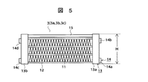
図5は、ラジエータ3の構成例を示すものである。ラジエータ3は、前述のように独立構成の単体ラジエータを組み合わせて構成される。冷却風との熱交換を行うコルゲートフィン11と、冷却液が流れる扁平チューブ12が、複数積み上げられ、これらを熱的に接合してラジエータコア17を構成し、これに冷却液を分配・集合するためのヘッダ13を組み合わせて構成する。ヘッダには液配管と接続するための接続コネクタ14(流入口側に接続コネクタ14a、14b、流出口側に接続コネクタ14c、14d)が取り付けられる。この接続コネクタは、図示した通り、一つのヘッダ13a、13bに対し上下に各一つ、合計2個取り付けることが望ましく、このような構成とすることで、単体ラジエータを複数組み合わせる際の配管の自由度を増すと同時に、ラジエータ3内に気体がトラップされるのを防止するような配管を可能にする。
Next, the configuration of the radiator applied to these embodiments will be described.
FIG. 5 shows a configuration example of the
また、液冷装置では、閉ループ内に浸透する気体をトラップするためのリザーバ5が必要なため、例えば図5に示すとおり、ラジエータ3の中にリザーバ15を設けてこれらを一体化することで、部品点数を低減することが望ましい。
Further, since the liquid cooling device requires the
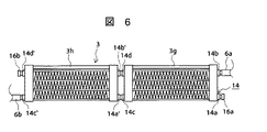
図6は、図5に示した単体ラジエータを2つ直列に組み合わせ、平面方向に並べて実装する場合の構成例であり、例えば第2実施形態で示した1U高さのサーバ向け液冷システムに適用できる構成である。この例にあっては単体ラジエータを横方向に組み合わせているが、この場合の横方向とは通風方向に対して直角(90°)をなす方向ということになる。この組み合わせにおいて、接続が不要な接続コネクタには封止キャップ16(16a、16b)を挿入し、必要な接続コネクタ14b、14c´のみに液配管6を接続する。単体ラジエータ3e、3f間の接続コネクタ14d、14b´;14c、14a、とをそれぞれ接続する。
FIG. 6 is a configuration example when two single radiators shown in FIG. 5 are combined in series and arranged side by side in the plane direction, and applied to the liquid cooling system for a server having a height of 1 U shown in the second embodiment, for example. It is a possible configuration. In this example, the single radiators are combined in the horizontal direction. In this case, the horizontal direction is a direction perpendicular to the ventilation direction (90 °). In this combination, sealing caps 16 (16a, 16b) are inserted into connection connectors that do not require connection, and the liquid pipe 6 is connected only to the
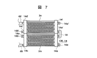
図7は、図5に示した単体ラジエータ3m、3nを2つ直列に組み合わせ、2段積みしてラジエータとして実装する場合の構成例であり、2U高さのサーバに適用することを想定している。接続コネクタ14bと14a´との間に接続配管18が設けられる。
FIG. 7 is a configuration example in the case where two
図8は、ラジエータ3の構成方法を示す。図において、ラジエータ3は、3つの独立したラジエータコア17(17a、17b、17c)と、これらのラジエータコア17の両端部に取り付けられるヘッダ13(13a、13b)とから構成される。ラジエータ17は、扁平状の管31(31a、31b、31c、31d)とその間に固定して配設されるフィン32(32a、32b、32c)からなるが、扁平状の管31とフィン32とが一体とされ1つの独立体として形成されていることが重要であり、このようにすることによって独立したラジエータコア17を同一形状で数倍化してラジエータ3を安価に製作できることになる。尚、扁平状の管31内を冷却液が流れるのは当然である。
FIG. 8 shows a method for configuring the
図9は、ラジエータコア17の要部を示す。図に示すように、ラジエータコア17は扁平状の管(すなわち、扁平チューブ)31a、31b、31c(31dは図示せず)およびフィン32a、32b、32cとからなり、フィン32a、32b、32cは、扁平状の管31a、31b、31c、31d間にそれぞれ配設され、固定され、独立体とされる。
図8において、ラジエータコア17a、17b、17cは、まったく同一方法によって構成される。
また、図1から図7におけるラジエータ3についても同一方法によって構成されている。
FIG. 9 shows a main part of the
In FIG. 8, the
The
図10は、図8に示す例の変形例であり、図8の例と同一部品については同一の番号を付し、説明を省略する。図10に示す例は、各ラジエータコア17a、17b、17cがそれぞれヘッダ13aa、13ba;13ab、13bb;13ac、13ccに別個に取り付けられる。従って、1つのラジエータコア17aと、ヘッダ13aa、13baとによって単体ラジエータ13a、13b、13cとが構成され、図1から図7に示すようなラジエータ3が構成される。
FIG. 10 is a modification of the example shown in FIG. 8. The same parts as those in the example of FIG. In the example shown in FIG. 10, the
これらの構成によれば、ラジエータは、前記冷却液を通す扁平状の管を複数有し、複数の管の間にフィンを配設し、固着して独立したラジエータコアが構成され、複数の前記ラジエータコアが並設されて、各ラジエータコアの両端部がそれぞれヘッダに接合されて、該ヘッダから前記管に冷却液が流れるようにして構成されることになる。 According to these configurations, the radiator has a plurality of flat tubes through which the cooling liquid passes, and fins are disposed between the plurality of tubes to form an independent radiator core. Radiator cores are arranged side by side, and both end portions of each radiator core are joined to headers, and the coolant flows from the headers to the pipes.
更には、ラジエータは、前記冷却液を通す扁平状の管を複数有し、複数の管の管にフィンを配設、固着して独立した1つのラジエータコアが構成され、該ラジエータコアの両端部がそれぞれヘッダに接合されて、該ヘッダから前記管に冷却液が流れるようにして単体ラジエータが構成され、かつ高さが44mm以下で、35mm以上とされた独立体として構成され、ヘッダに少なくとも2個以上の流入口側コネクタ、2個以上の流出口側コネクタを備えた前記単体ラジエータが、複数個高さ方向および横方向に組み立てられるものであって、高さ方向および横方向のいずれかの方向に組み立てられて構成されることになる。 Further, the radiator has a plurality of flat tubes through which the cooling liquid passes, and fins are arranged and fixed to the tubes of the plurality of tubes to form an independent radiator core, and both ends of the radiator core are configured. Are joined to the header, and a single radiator is configured such that the coolant flows from the header to the pipe, and is configured as an independent body having a height of 44 mm or less and 35 mm or more. A plurality of the single radiators having two or more inlet-side connectors and two or more outlet-side connectors are assembled in the height direction and the horizontal direction, and either one of the height direction and the horizontal direction is assembled. It will be assembled in the direction.
図8から図10に、ラジエータ3の構成方法について示した。図8において、冷却風との熱交換を行うフィン32と、冷却液が流れる扁平状の管31とからなるラジエータコア17が、複数積み上げてラジエータ3を構成しており、このラジエータコア3を様々な筐体高さのサーバに適用可能な共通コンポーネントとするものである。図10の例にあっては、1U高さで構成するラジエータコア17を横方向に3つ並べ、ラジエータ3を形成することを行っており、部品コンポーネントを共通化しつつ、通風断面積を、筐体高さに合わせて広く確保することが可能となる。
FIG. 8 to FIG. 10 show a configuration method of the
ここに示した実施形態では、液冷システムで冷却する部品をCPU101として説明したが、メモリ102やチップセット、HDD等のストレージデバイス105をこのような液冷システムで冷却するようにしてもよい。この場合には、冷却が必要な部品にそれぞれ液冷ジャケットを熱接続し、冷却液の循環路にCPUの冷却と直列または並列に接続するようにするのがよい。
In the embodiment shown here, the components to be cooled by the liquid cooling system have been described as the
1…ポンプ、2…液冷ジャケット、3…ラジエータ、4…冷却ファン、5…気液分離機構付きリザーバ、6…液配管、11…液チューブ、12…コルゲートフィン、13…ヘッダ、14…接続コネクタ、15…リザーバ、16…封止キャップ、17…ラジエータコア、101…CPU、102…メモリ、103…メインボード、104…電源ユニット、105…ストレージデバイス、106…拡張ボード、107…3U筐体向け液冷システム、108…1U筐体向け液冷システム。
DESCRIPTION OF
Claims (6)
前記ラジエータは、前記冷却液を通す扁平状の管を複数有し、複数の管の間にフィンを配設、固着して独立したラジエータコアが構成され、複数の前記ラジエータコアが並設されて、各ラジエータコアの両端部がそれぞれヘッダに接合されて、該ヘッダから前記管に冷却液が流れるようにして構成されること
を特徴とする液冷却装置。 In a liquid cooling apparatus for an electronic device comprising a pump for circulating a cooling liquid, a liquid cooling jacket that absorbs heat generated from a heat generating part into the cooling liquid, and a radiator that radiates heat stored in the cooling liquid to the outside air,
The radiator has a plurality of flat tubes through which the cooling liquid passes, and fins are disposed between the plurality of tubes and fixed to form an independent radiator core. The plurality of radiator cores are arranged in parallel. A liquid cooling device, wherein both ends of each radiator core are joined to a header so that a cooling liquid flows from the header to the pipe.
前記ラジエータは、高さが44mm以下で、35mm以上とされた独立体として構成され、ヘッダに少なくとも2個以上の流入口側コネクタ、2個以上の流出口側コネクタを備えた単体ラジエータが、複数個高さ方向および横方向に組み立てられるものであって、高さ方向および横方向のいずれかの方向に組み立てられて構成されること
を特徴とする液冷装置。 In a liquid cooling apparatus for an electronic device comprising a pump for circulating a cooling liquid, a liquid cooling jacket that absorbs heat generated from a heat generating part into the cooling liquid, and a radiator that radiates heat stored in the cooling liquid to the outside air,
The radiator is configured as an independent body having a height of 44 mm or less and 35 mm or more, and a plurality of unit radiators having at least two or more inlet-side connectors and two or more outlet-side connectors in a header. A liquid cooling device, which is assembled in the height direction and the horizontal direction, and is assembled in either the height direction or the horizontal direction.
前記ラジエータは、前記冷却液を通す扁平状の管を複数有し、複数の管の管にフィンを配設、固着して独立した1つのラジエータコアが構成され、該ラジエータコアの両端部がそれぞれヘッダに接合されて、該ヘッダから前記管に冷却液が流れるようにして単体ラジエータが構成され、かつ高さが44mm以下で、35mm以上とされた独立体として構成され、ヘッダに少なくとも2個以上の流入口側コネクタ、2個以上の流出口側コネクタを備えた前記単体ラジエータが、複数個高さ方向および横方向に組み立てられるものであって、高さ方向および横方向のいずれかの方向に組み立てられて構成されること
を特徴とする液冷装置。 In a liquid cooling apparatus for an electronic device comprising a pump for circulating a cooling liquid, a liquid cooling jacket that absorbs heat generated from a heat generating part into the cooling liquid, and a radiator that radiates heat stored in the cooling liquid to the outside air,
The radiator has a plurality of flat tubes through which the cooling liquid passes, and fins are disposed on the tubes of the plurality of tubes and fixed to form an independent radiator core, and both ends of the radiator core are respectively A single radiator is configured to be joined to the header so that cooling liquid flows from the header to the pipe, and is configured as an independent body having a height of 44 mm or less and 35 mm or more. A plurality of the single radiators having two or more outlet-side connectors are assembled in the height direction and the lateral direction, and in either the height direction or the lateral direction. A liquid cooling device characterized by being assembled.
前記液冷装置を構成する前記ラジエータは、高さが44mm以下で、35mm以上とされた独立体として構成され、ヘッダに少なくとも2個以上の流入口側コネクタ、2個以上の流出口側コネクタを備えた単体ラジエータが、複数個高さ方向および横方向に組み立てられるものであって、高さ方向および横方向のいずれかの方向に組み立てられて構成されること
を特徴とする電子機器。 In an electronic device that houses in a cabinet a liquid cooling device that includes a pump that circulates the cooling liquid, a liquid cooling jacket that absorbs heat generated from the heat generating part into the cooling liquid, and a radiator that radiates heat stored in the cooling liquid to the outside air.
The radiator constituting the liquid cooling device is configured as an independent body having a height of 44 mm or less and 35 mm or more, and at least two inlet-side connectors and two or more outlet-side connectors are provided on the header. An electronic apparatus comprising: a plurality of unit radiators that are assembled in a height direction and a horizontal direction, and are assembled in either the height direction or the horizontal direction.
前記液冷装置を構成する前記ラジエータは、前記冷却液を通す扁平状の管を複数有し、複数の管の管にフィンを配設、固着して独立した1つのラジエータコアが構成され、該ラジエータコアの両端部がそれぞれヘッダに接合されて、該ヘッダから前記管に冷却液が流れるようにして単体ラジエータが構成され、かつ高さが44mm以下で、35mm以上とされた独立体として構成され、ヘッダに少なくとも2個以上の流入口側コネクタ、2個以上の流出口側コネクタを備えた前記単体ラジエータが、複数個高さ方向および横方向に組み立てられるものであって、高さ方向および横方向のいずれかの方向に組み立てられて構成されること
を特徴とする電子機器。
In an electronic device that houses in a cabinet a liquid cooling device that includes a pump that circulates the cooling liquid, a liquid cooling jacket that absorbs heat generated from the heat generating part into the cooling liquid, and a radiator that radiates heat stored in the cooling liquid to the outside air.
The radiator constituting the liquid cooling device includes a plurality of flat tubes through which the cooling liquid passes, and a single radiator core is configured by disposing and fixing fins to the tubes of the plurality of tubes, Both ends of the radiator core are joined to the header, and a single radiator is configured so that the coolant flows from the header to the pipe, and the height is 44 mm or less and is configured as an independent body that is 35 mm or more. A plurality of the single radiators having at least two or more inlet-side connectors and two or more outlet-side connectors in the header are assembled in the height direction and the lateral direction, An electronic device characterized by being assembled in any direction.
Priority Applications (6)
| Application Number | Priority Date | Filing Date | Title |
|---|---|---|---|
| JP2003357245A JP2005122503A (en) | 2003-10-17 | 2003-10-17 | Cooling apparatus and electronic equipment incorporating the same |
| TW093105588A TWI289039B (en) | 2003-10-17 | 2004-03-03 | Cooling apparatus and electronic equipment incorporating the same |
| EP04005162A EP1524888A3 (en) | 2003-10-17 | 2004-03-04 | Cooling device and electronic apparatus building in the same |
| KR1020040014477A KR100608958B1 (en) | 2003-10-17 | 2004-03-04 | Cooling device and electronic appliance internally mounting the same |
| US10/792,716 US20050081534A1 (en) | 2003-10-17 | 2004-03-05 | Cooling device and electronic apparatus building in the same |
| CNA200410007771XA CN1610009A (en) | 2003-10-17 | 2004-03-05 | Cooling device and electronic apparatus building in the same |
Applications Claiming Priority (1)
| Application Number | Priority Date | Filing Date | Title |
|---|---|---|---|
| JP2003357245A JP2005122503A (en) | 2003-10-17 | 2003-10-17 | Cooling apparatus and electronic equipment incorporating the same |
Publications (2)
| Publication Number | Publication Date |
|---|---|
| JP2005122503A true JP2005122503A (en) | 2005-05-12 |
| JP2005122503A5 JP2005122503A5 (en) | 2006-08-03 |
Family
ID=34373616
Family Applications (1)
| Application Number | Title | Priority Date | Filing Date |
|---|---|---|---|
| JP2003357245A Pending JP2005122503A (en) | 2003-10-17 | 2003-10-17 | Cooling apparatus and electronic equipment incorporating the same |
Country Status (6)
| Country | Link |
|---|---|
| US (1) | US20050081534A1 (en) |
| EP (1) | EP1524888A3 (en) |
| JP (1) | JP2005122503A (en) |
| KR (1) | KR100608958B1 (en) |
| CN (1) | CN1610009A (en) |
| TW (1) | TWI289039B (en) |
Cited By (8)
| Publication number | Priority date | Publication date | Assignee | Title |
|---|---|---|---|---|
| JP2008027372A (en) * | 2006-07-25 | 2008-02-07 | Fujitsu Ltd | Heat exchanger for liquid cooling unit, liquid cooling unit, and electronic device |
| JP2008122070A (en) * | 2006-11-10 | 2008-05-29 | Visteon Global Technologies Inc | Heat exchanger used as evaporator of air-conditioning unit for vehicle |
| JP2011047616A (en) * | 2009-08-28 | 2011-03-10 | Hitachi Ltd | Cooling system and electronic device using the same |
| JP2013003636A (en) * | 2011-06-13 | 2013-01-07 | Ntt Facilities Inc | Server rack cooling apparatus |
| JP2013145830A (en) * | 2012-01-16 | 2013-07-25 | Nikkei Nekko Kk | Radiator in liquid cooled system for electronic apparatus |
| JP2014502687A (en) * | 2010-12-14 | 2014-02-03 | スカニア シーブイ アクチボラグ | MODULE SYSTEM FOR FORMING RADIATOR DEVICE, AND SUPPLIER AND RADIATOR LIQUID COOLER FORMED BY SUCH MODULE SYSTEM |
| JP2016131168A (en) * | 2015-01-13 | 2016-07-21 | 富士通株式会社 | Heat exchanger, cooling unit, and electronic device |
| JP7079038B1 (en) | 2021-12-01 | 2022-06-01 | Ard株式会社 | Computer |
Families Citing this family (38)
| Publication number | Priority date | Publication date | Assignee | Title |
|---|---|---|---|---|
| JP2006215882A (en) * | 2005-02-04 | 2006-08-17 | Hitachi Ltd | Disk array device and liquid cooling device |
| EP1881394A1 (en) * | 2006-07-20 | 2008-01-23 | Silver-Stone Technology Co., Ltd. | Liquid-cooling heat dissipating device for dissipating heat by a casing |
| JP5283836B2 (en) | 2006-07-25 | 2013-09-04 | 富士通株式会社 | Heat receiver and liquid cooling unit for liquid cooling unit and electronic device |
| JP4842040B2 (en) * | 2006-07-25 | 2011-12-21 | 富士通株式会社 | Electronics |
| JP2008027370A (en) * | 2006-07-25 | 2008-02-07 | Fujitsu Ltd | Electronic device |
| JP5133531B2 (en) * | 2006-07-25 | 2013-01-30 | 富士通株式会社 | Heat exchanger for liquid cooling unit, liquid cooling unit and electronic equipment |
| JP4781929B2 (en) | 2006-07-25 | 2011-09-28 | 富士通株式会社 | Electronics |
| JP2008027374A (en) | 2006-07-25 | 2008-02-07 | Fujitsu Ltd | Heat receiver for liquid cooling unit, liquid cooling unit, and electronic device |
| JP2008122058A (en) * | 2006-10-17 | 2008-05-29 | Alps Electric Co Ltd | Radiator and cooling system |
| US8118084B2 (en) * | 2007-05-01 | 2012-02-21 | Liebert Corporation | Heat exchanger and method for use in precision cooling systems |
| EP2277365B1 (en) | 2008-05-16 | 2011-11-02 | Parker-Hannifin Corporation | Modular high-power drive stack cooled with vaporizable dielectric fluid |
| US9238398B2 (en) * | 2008-09-25 | 2016-01-19 | B/E Aerospace, Inc. | Refrigeration systems and methods for connection with a vehicle's liquid cooling system |
| JP5531573B2 (en) * | 2008-12-09 | 2014-06-25 | 日本軽金属株式会社 | Method for joining resin member and metal member, method for manufacturing liquid cooling jacket, and liquid cooling jacket |
| US8369090B2 (en) | 2009-05-12 | 2013-02-05 | Iceotope Limited | Cooled electronic system |
| CN102834688B (en) * | 2010-03-29 | 2015-07-15 | 日本电气株式会社 | Phase change cooler and electronic equipment provided with same |
| WO2011122207A1 (en) * | 2010-03-30 | 2011-10-06 | 日本電気株式会社 | Cooling apparatus and cooling system for electronic-device exhaustion |
| CN103930847A (en) * | 2011-10-26 | 2014-07-16 | 惠普发展公司,有限责任合伙企业 | Device for cooling an electronic component in a data center |
| JP6127416B2 (en) * | 2012-09-07 | 2017-05-17 | 富士通株式会社 | Electronics |
| US10018101B2 (en) * | 2013-01-18 | 2018-07-10 | Robert D. Seligman | Cooling system and a method for its use |
| WO2016031186A1 (en) * | 2014-08-27 | 2016-03-03 | 日本電気株式会社 | Phase-change cooling device, and phase-change cooling method |
| TWI575212B (en) * | 2014-09-24 | 2017-03-21 | 台達電子工業股份有限公司 | Reversible liquid cooling device and reverse method thereof |
| WO2016122666A1 (en) * | 2015-01-30 | 2016-08-04 | Hewlett Packard Enterprise Development Lp | Integrated liquid cooling of a server system |
| TWM505162U (en) * | 2015-02-04 | 2015-07-11 | Man Zai Ind Co Ltd | Refrigerant type heat dissipation device and evaporator with heat dissipation fin |
| JP6555081B2 (en) * | 2015-10-30 | 2019-08-07 | 富士通株式会社 | Sealed loop circulating liquid cooling device and electronic equipment |
| CN107734916B (en) * | 2016-08-11 | 2020-04-28 | 技嘉科技股份有限公司 | Liquid cooling type heat dissipation system |
| TWM534958U (en) * | 2016-09-30 | 2017-01-01 | 微星科技股份有限公司 | Liquid cooling heat dissipating module |
| JP6862777B2 (en) * | 2016-11-11 | 2021-04-21 | 富士通株式会社 | Manifold and information processing equipment |
| TWM553548U (en) * | 2017-09-05 | 2017-12-21 | 訊凱國際股份有限公司 | Radiator |
| US10578368B2 (en) * | 2018-01-19 | 2020-03-03 | Asia Vital Components Co., Ltd. | Two-phase fluid heat transfer structure |
| CN108509001B (en) * | 2018-04-02 | 2021-01-15 | 联想(北京)有限公司 | Electronic equipment and water-cooling server thereof |
| JP7131312B2 (en) * | 2018-11-07 | 2022-09-06 | 日本電産株式会社 | Cooling system |
| US11713928B2 (en) * | 2019-11-07 | 2023-08-01 | Carrier Corporation | Microchannel heat exchanger having auxiliary headers and core |
| CN113672059A (en) * | 2020-05-15 | 2021-11-19 | 亚浩电子五金塑胶(惠州)有限公司 | Computer liquid cooling system |
| AU2020459333A1 (en) | 2020-07-20 | 2022-05-26 | Ivan Kirillov | Fast flow cooling bath for multiprocessor circuit boards |
| CN114063371B (en) * | 2020-07-31 | 2023-05-26 | 中强光电股份有限公司 | Liquid cooling device and projection equipment |
| CN114554779A (en) * | 2020-11-24 | 2022-05-27 | 华为技术有限公司 | Heat dissipation device and vehicle |
| CN113242680A (en) | 2021-05-28 | 2021-08-10 | 惠州汉旭五金塑胶科技有限公司 | Liquid cooling radiator capable of improving radiating effect |
| TWI813381B (en) * | 2022-07-15 | 2023-08-21 | 技嘉科技股份有限公司 | Electronic device and heat dissipation assembly thereof |
Family Cites Families (28)
| Publication number | Priority date | Publication date | Assignee | Title |
|---|---|---|---|---|
| FR2580060B1 (en) * | 1985-04-05 | 1989-06-09 | Nec Corp | |
| JPH02140166U (en) * | 1989-04-24 | 1990-11-22 | ||
| US5529116A (en) * | 1989-08-23 | 1996-06-25 | Showa Aluminum Corporation | Duplex heat exchanger |
| JPH081418Y2 (en) * | 1989-12-08 | 1996-01-17 | カルソニック株式会社 | Multilayer heat exchanger adapter |
| US5285347A (en) * | 1990-07-02 | 1994-02-08 | Digital Equipment Corporation | Hybird cooling system for electronic components |
| US5348081A (en) * | 1993-10-12 | 1994-09-20 | General Motors Corporation | High capacity automotive condenser |
| JP3355824B2 (en) | 1994-11-04 | 2002-12-09 | 株式会社デンソー | Corrugated fin heat exchanger |
| JPH08237148A (en) * | 1995-03-01 | 1996-09-13 | Mitsubishi Electric Corp | Cooler for module transmitter |
| JPH0961084A (en) * | 1995-08-28 | 1997-03-07 | Showa Alum Corp | Manufacture of inlet or outlet pipe for stacked type heat exchanger |
| DE19709934B4 (en) * | 1996-03-14 | 2008-04-17 | Denso Corp., Kariya | Refrigerator for boiling and condensing a refrigerant |
| US6205803B1 (en) * | 1996-04-26 | 2001-03-27 | Mainstream Engineering Corporation | Compact avionics-pod-cooling unit thermal control method and apparatus |
| KR200273141Y1 (en) * | 1996-08-21 | 2002-09-17 | 한라공조주식회사 | heat transmitter |
| US5901037A (en) * | 1997-06-18 | 1999-05-04 | Northrop Grumman Corporation | Closed loop liquid cooling for semiconductor RF amplifier modules |
| US6167947B1 (en) * | 1998-12-18 | 2001-01-02 | Silicon Graphics, Inc. | High performance gas cooling system and method |
| KR200355174Y1 (en) * | 1999-06-30 | 2004-07-06 | 한라공조주식회사 | Manifold tube having structure to enhance cooling effect and heat exchanger using it |
| US6360814B1 (en) * | 1999-08-31 | 2002-03-26 | Denso Corporation | Cooling device boiling and condensing refrigerant |
| US6166907A (en) * | 1999-11-26 | 2000-12-26 | Chien; Chuan-Fu | CPU cooling system |
| JP2002198675A (en) * | 2000-12-26 | 2002-07-12 | Fujitsu Ltd | Electronic apparatus |
| JP2002232174A (en) * | 2001-02-06 | 2002-08-16 | Hitachi Ltd | Electronic device |
| KR20020090006A (en) * | 2001-05-25 | 2002-11-30 | 엘지전자 주식회사 | Heat exchanger of Alumimun |
| JP2002366258A (en) | 2001-06-01 | 2002-12-20 | Internatl Business Mach Corp <Ibm> | Electronic equipment system and vertical rack |
| JP2002374086A (en) | 2001-06-15 | 2002-12-26 | Hitachi Ltd | Cooling method of rack mounting information processor |
| KR100714086B1 (en) * | 2001-07-11 | 2007-05-02 | 한라공조주식회사 | Adaptor for evaporator |
| JP3961843B2 (en) | 2002-02-08 | 2007-08-22 | 株式会社日立製作所 | A small computer with a liquid cooling system. |
| US6749012B2 (en) * | 2002-04-30 | 2004-06-15 | Intel Corporation | Liquid cooling system for processors |
| JP4012773B2 (en) | 2002-07-08 | 2007-11-21 | 株式会社日立製作所 | Electronics |
| US6754076B2 (en) * | 2002-10-30 | 2004-06-22 | International Business Machines Corporation | Stackable liquid cooling pump |
| US6809928B2 (en) * | 2002-12-27 | 2004-10-26 | Intel Corporation | Sealed and pressurized liquid cooling system for microprocessor |
-
2003
- 2003-10-17 JP JP2003357245A patent/JP2005122503A/en active Pending
-
2004
- 2004-03-03 TW TW093105588A patent/TWI289039B/en not_active IP Right Cessation
- 2004-03-04 KR KR1020040014477A patent/KR100608958B1/en not_active IP Right Cessation
- 2004-03-04 EP EP04005162A patent/EP1524888A3/en not_active Withdrawn
- 2004-03-05 CN CNA200410007771XA patent/CN1610009A/en active Pending
- 2004-03-05 US US10/792,716 patent/US20050081534A1/en not_active Abandoned
Cited By (10)
| Publication number | Priority date | Publication date | Assignee | Title |
|---|---|---|---|---|
| JP2008027372A (en) * | 2006-07-25 | 2008-02-07 | Fujitsu Ltd | Heat exchanger for liquid cooling unit, liquid cooling unit, and electronic device |
| JP2008122070A (en) * | 2006-11-10 | 2008-05-29 | Visteon Global Technologies Inc | Heat exchanger used as evaporator of air-conditioning unit for vehicle |
| JP2011047616A (en) * | 2009-08-28 | 2011-03-10 | Hitachi Ltd | Cooling system and electronic device using the same |
| US8345425B2 (en) | 2009-08-28 | 2013-01-01 | Hitachi, Ltd. | Cooling system and electronic apparatus applying the same therein |
| JP2014502687A (en) * | 2010-12-14 | 2014-02-03 | スカニア シーブイ アクチボラグ | MODULE SYSTEM FOR FORMING RADIATOR DEVICE, AND SUPPLIER AND RADIATOR LIQUID COOLER FORMED BY SUCH MODULE SYSTEM |
| JP2013003636A (en) * | 2011-06-13 | 2013-01-07 | Ntt Facilities Inc | Server rack cooling apparatus |
| JP2013145830A (en) * | 2012-01-16 | 2013-07-25 | Nikkei Nekko Kk | Radiator in liquid cooled system for electronic apparatus |
| JP2016131168A (en) * | 2015-01-13 | 2016-07-21 | 富士通株式会社 | Heat exchanger, cooling unit, and electronic device |
| JP7079038B1 (en) | 2021-12-01 | 2022-06-01 | Ard株式会社 | Computer |
| JP2023081408A (en) * | 2021-12-01 | 2023-06-13 | Ard株式会社 | Computer |
Also Published As
| Publication number | Publication date |
|---|---|
| CN1610009A (en) | 2005-04-27 |
| TWI289039B (en) | 2007-10-21 |
| KR20050037335A (en) | 2005-04-21 |
| KR100608958B1 (en) | 2006-08-08 |
| TW200515865A (en) | 2005-05-01 |
| EP1524888A3 (en) | 2007-10-17 |
| US20050081534A1 (en) | 2005-04-21 |
| EP1524888A2 (en) | 2005-04-20 |
Similar Documents
| Publication | Publication Date | Title |
|---|---|---|
| JP2005122503A (en) | Cooling apparatus and electronic equipment incorporating the same | |
| JP4859823B2 (en) | COOLING DEVICE AND ELECTRONIC DEVICE USING THE SAME | |
| US8203842B2 (en) | Open flow cold plate for immersion-cooled electronic packages | |
| US9560794B2 (en) | Cooling device for cooling rack-type server, and data center provided with same | |
| JP2008287733A (en) | Liquid cooling system | |
| US8929080B2 (en) | Immersion-cooling of selected electronic component(s) mounted to printed circuit board | |
| US7400505B2 (en) | Hybrid cooling system and method for a multi-component electronics system | |
| US6421240B1 (en) | Cooling arrangement for high performance electronic components | |
| US7068509B2 (en) | Small form factor cooling system | |
| US20050259397A1 (en) | Small form factor liquid loop cooling system | |
| US20080084668A1 (en) | Conductive heat transport cooling system and method for a multi-component electronics system | |
| US9795064B2 (en) | Heat exchanger, cooling unit, and electronic device | |
| JP2004246649A (en) | Rack-mounted server system, rack cabinet, server module, and cooling method of rack-mounted server system | |
| JP2005331233A (en) | Multipath heat exchanger having gap between fins of adjacent pipe portions | |
| KR20100045366A (en) | Liquid cooling apparatus and method for cooling blades of an electronic system chassis | |
| GB2413439A (en) | Liquid loop cooling system space utilization | |
| JP6126149B2 (en) | Air-cooled laser apparatus provided with a heat conducting member having a radiation fin | |
| JP5664397B2 (en) | Cooling unit | |
| US20130206367A1 (en) | Heat dissipating module | |
| US10874034B1 (en) | Pump driven liquid cooling module with tower fins | |
| JP2004319628A (en) | System module | |
| JP2008060515A (en) | Cooling device for electronic control device | |
| JP4603783B2 (en) | Liquid cooling system and radiator | |
| JP7298216B2 (en) | Server cooling device, server system, and server cooling method | |
| JP2007027340A (en) | Cooling device for electronic equipment |
Legal Events
| Date | Code | Title | Description |
|---|---|---|---|
| A521 | Written amendment |
Free format text: JAPANESE INTERMEDIATE CODE: A523 Effective date: 20060608 |
|
| A621 | Written request for application examination |
Free format text: JAPANESE INTERMEDIATE CODE: A621 Effective date: 20060608 |
|
| A131 | Notification of reasons for refusal |
Free format text: JAPANESE INTERMEDIATE CODE: A131 Effective date: 20090303 |
|
| A521 | Written amendment |
Free format text: JAPANESE INTERMEDIATE CODE: A523 Effective date: 20090415 |
|
| A02 | Decision of refusal |
Free format text: JAPANESE INTERMEDIATE CODE: A02 Effective date: 20090915 |