JP2005016861A - Cooled gas duct changing device for vacuum heat treatment furnace - Google Patents
Cooled gas duct changing device for vacuum heat treatment furnace Download PDFInfo
- Publication number
- JP2005016861A JP2005016861A JP2003183968A JP2003183968A JP2005016861A JP 2005016861 A JP2005016861 A JP 2005016861A JP 2003183968 A JP2003183968 A JP 2003183968A JP 2003183968 A JP2003183968 A JP 2003183968A JP 2005016861 A JP2005016861 A JP 2005016861A
- Authority
- JP
- Japan
- Prior art keywords
- cooling
- gas
- cooling chamber
- partition plate
- heat treatment
- Prior art date
- Legal status (The legal status is an assumption and is not a legal conclusion. Google has not performed a legal analysis and makes no representation as to the accuracy of the status listed.)
- Granted
Links
Images


Abstract
Description
【0001】
【発明の属する技術分野】
本発明は、真空熱処理炉の冷却ガス風路切替え装置に関する。
【0002】
【従来の技術】
真空熱処理炉は、内部を減圧した後、不活性ガス等を再充填して被処理品を熱処理する熱処理炉である。真空熱処理炉は、加熱後に炉内及び処理品についた水分等がガス化した後に再度減圧し、不活性ガス等を再充填することで、水分を完全に除去できるため、水分による色付きのない熱処理(「光輝熱処理」と呼ぶ)ができる利点がある。
【0003】
また、ガス冷却式真空熱処理炉は、光輝熱処理ができ、かつ脱炭浸炭がない、変形が少ない、作業環境が良いなど、種々の利点を有する。しかし、初期のガス冷却式真空熱処理炉は、減圧冷却式であるため、冷却速度が不十分な欠点があった。そこで、冷却速度を高めるために、高速循環ガス冷却方式が実用化されている。
【0004】
図7は、非特許文献1に開示された高速循環ガス冷却炉の構成図である。この図において、50は断熱材、51はヒータ、52は有効作業域、53は炉体及び水冷ジャケット、54は熱交換器、55はターボファン、56はファン用モータ、57は冷却扉、58は炉床、59はガスディストリビュータ、60は冷却ガスの風路を切替えるダンパーである。
【0005】
また、特許文献1の「真空炉におけるガス循環冷却促進法」は、図8に示すように、気密性の真空容器61内に断熱壁67によって囲った加熱室66を設け、加熱室内に配置されたヒータ62により被熱物64を真空中で加熱すると共に、真空容器61内にクーラ62およびファン63が設けられ真空容器内に供給された無酸化性ガスをクーラ62により冷却し、無酸化性ガスをファン63の回転により加熱室66の相対する断熱壁67面に設けられた開口68,69より加熱室66内に循環させて被熱物64を強制ガス循環冷却する真空炉において、少なくとも一端が末広がり状に形成れた耐熱性の筒状フード65を加熱室66内に置かれた被熱物64の周囲を適宜間隔を離して囲うように、かつその両端が前記開口68,69に相対するように配置して無酸化性ガスを加熱室66内に循環させるようにしたものである。なお、この図において70は冷却ガスの風路を切替えるダンパーである。
【0006】
【非特許文献1】
山崎勝弘,金属材料の真空熱処理(2),熱処理30巻2号,平成2年4月
【特許文献1】
特開平5−230528号公報
【0007】
【発明が解決しようとする課題】
上述した非特許文献1及び特許文献1に記載の高速循環ガス冷却炉において、上向きと下向きの風路を切り替える機構として上下にダンパー装置が通常用いられている。しかし、上下のダンパー装置を風路切替え機構とした場合、以下の問題点があった。
(1)ダンパー装置は、その開閉位置により高速で通過する風圧による負荷変動が大きい。そのため、高圧ガスの場合にダンパー方式では風圧の影響でスムースに動かすことが困難である。
(2)ダンパー装置は、開閉角度と開口面積が比例しない。そのため、上下の複数の駆動装置を切り替える際に、開口面積のバランスを整えることが難しく、吸込口及び吐出口の開口面積に差が生じたり、その変動が大きくなり、冷却ガス量が変動し、安定したガス冷却が困難である。
(3)上下に複数のダンパー装置が存在し、複数の駆動装置が必要であり、構造が複雑となる。
(4)開口面積が上下にダンパー装置で限定され、炉体内面積に比べて小さい。
【0008】
本発明は、上述した問題点を解決するために創案されたものである。すなわち、本発明の目的は、風圧の影響を受けにくくスムースに風路を切替えることができ、開口面積の変動や吸込口と吐出口の開口面積差が生じにくく、安定したガス冷却が可能であり、構造が簡潔であり単一の駆動装置で切替えが可能であり、大きな開口面積を確保できる真空熱処理炉の冷却ガス風路切替え装置を提供することにある。
【0009】
【課題を解決するための手段】
本発明によれば、被処理品を静置する冷却領域を囲む冷却室と、該冷却室内を通過するガスを冷却して循環させるガス冷却循環装置とを備え、加熱した被処理品を加圧した循環ガスで冷却する真空熱処理炉の冷却ガス風路切替え装置であって、冷却室とガス冷却循環装置との間を仕切る固定仕切板と、該固定仕切板の表面に沿って回転駆動される回転仕切板とを有し、固定仕切板はほぼ全面を貫通する開口を有し、回転仕切板は、ガス冷却循環装置の吸込口と吐出口に部分的に連通する吸引開口と吐出開口を有し、これにより冷却室内を通過するガスの方向を交互に切り替える、ことを特徴とする真空熱処理炉の冷却ガス風路切替え装置が提供される。
【0010】
上記本発明の構成によれば、冷却室とガス冷却循環装置との間を仕切る固定仕切板の表面に沿って回転仕切板を回転駆動するだけで、冷却室内を通過するガスの方向を交互に切り替えるので、流れ方向に対して回転仕切板が垂直に動く回転駆動であるため、高圧ガス(密度が高いガス体)であっても風圧の影響を受けにくくスムースに風路を切替えることができる。
また、回転仕切板が、ガス冷却循環装置の吸込口と吐出口に部分的に連通する吸引開口と吐出開口を有するので、開口面積の変動や吸込口と吐出口の開口面積差が生じにくく、安定したガス冷却が可能である。また、構造が簡潔であり単一の駆動装置で切替えが可能であり、大きな開口面積を確保できる。
【0011】
本発明の好ましい第1実施形態によれば、前記冷却室は、その内側を上下方向に通過するガス流路を有し、冷却室内をガスが下方に流れるときに、吸引開口が冷却室の下方のみと連通しかつ吐出開口が冷却室の上方のみと連通し、冷却室内をガスが上方に流れるときに、吸引開口が冷却室の上方のみと連通しかつ吐出開口が冷却室の下方のみと連通するように開口位置が設定されている。
【0012】
この構成により、冷却室とガス冷却循環装置との間を仕切る炉体内面積Aのうち、1/2づつをガス冷却循環装置の吸込口と吐出口とし、更に吸込口と吐出口のうち、1/2づつを下方、上方とすることで、吸引開口と吐出開口を炉体内面積Aの約1/4づつに設定することができる。従って、従来に比較して風路面積を大きくとれ、ガスの通過流速を低減でき、圧損を小さくできる。
また、固定仕切板とガス冷却循環装置の間は、内側全面がガス冷却循環装置の吸込口に連通し、外側全面だガス冷却循環装置の吐出口に連通しているので、吐出口/吸込み口の隙間を十分取ることで半面しか開口していなくても反対面への回り込みが可能となり、熱交換器全体を有効利用できる。
【0013】
本発明の好ましい第2実施形態によれば、前記冷却室内をガスが上下方向に流れるときに、吸引開口が冷却室の下方のみ又は上方のみと選択的に連通しかつ吐出開口が冷却室の上方のみ又は下方のみと選択的に連通し、前記冷却室内をガスが水平方向に流れるときに、吸引開口が冷却室のいずれかの片側のみに選択的に連通しかつ吐出開口が冷却室の反対の片側のみと選択的に連通するように開口位置が設定されている。
【0014】
この構成により、冷却室とガス冷却循環装置との間を仕切る固定仕切板の表面に沿って回転仕切板を回転駆動するだけで、冷却室内を通過するガスの方向を上下方向及び左右方向に自由に切り替えることができる。
【0015】
前記ガス冷却循環装置は、冷却室に隣接して設置され冷却室を通過したガスを吸引して加圧する冷却ファンと、該冷却ファンから吐出されるガスを間接冷却する熱交換器とからなる。
【0016】
この構成により、固定仕切板とガス冷却循環装置の間は、内側全面がガス冷却循環装置の吸込口に連通し、外側全面だガス冷却循環装置の吐出口に連通しているので、吐出口/吸込み口の隙間を十分取ることで半面しか開口していなくても反対面への回り込みが可能となり、熱交換器全体を有効利用できる。
【0017】
【発明の実施の形態】
以下、本発明の好ましい実施形態を図面を参照して説明する。なお、各図において、共通する部分には同一の符号を付し、重複した説明を省略する。
【0018】
図1は、本発明の第1実施形態の冷却ガス風路切替え装置を備えた真空熱処理炉の全体構成図である。この図において、この真空熱処理炉は、真空加熱炉10、ガス冷却炉20、及び移動装置30を備えた多室型熱処理炉である。
真空加熱炉10は、被処理品1を減圧下で加熱する機能を有する。ガス冷却炉20は、加熱した被処理品1を加圧した循環ガス2で冷却する機能を有する。移動装置30は、被処理品1を真空加熱炉10とガス冷却炉20との間で移動する機能を有する。
【0019】
真空加熱炉10は、内部が真空排気されるようになった真空容器11、被処理品1を内部に収容する加熱室12、加熱室に被処理品1を出し入れするための前扉13、加熱室内の被処理品1を移動させるための開口を閉じる後扉14、被処理品1を前後に水平移動可能に載せる載置台15、被処理品1を加熱するためのヒータ16、等からなる。この構成により、真空容器11の内部を真空に減圧し、ヒータ16により被処理品1を所定の温度まで加熱することができる。
【0020】
移動装置30は、被処理品1を真空加熱炉10とガス冷却炉20との間で水平に移動させる搬送棒32、後扉14を昇降させて開閉する後扉昇降装置33、前扉13を昇降させて開閉する前扉昇降装置34、及びガス冷却炉20の中間断熱扉21aを昇降させて開閉する中間扉昇降装置34を備える。この例において、搬送棒32はラックピニオン駆動、後扉昇降装置33は直動シリンダ、前扉昇降装置34と中間扉昇降装置34は巻上げ機であるが、本発明はこれに限定されず、その他の駆動機構であってもよい。この構成により、後扉14、前扉13及び中間断熱扉21aを開放した状態で、搬送棒32により、被処理品1を真空加熱炉10とガス冷却炉20との間で水平に移動させることができる。
【0021】
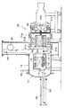
図2は図1の部分拡大図であり、図3は図2のA−A線における断面図である。図1〜図3に示すように、ガス冷却炉20は、真空容器21、冷却室22、ガス冷却循環装置24、冷却ガス風路切替え装置40及び整流器28を備える。
真空容器21は、真空加熱炉10の前扉13に対向して設けられた中間断熱扉21a、被処理品1を内部に収容する円筒形の容器胴部21b、ガス冷却循環装置24を収容する循環部21c、気密に開閉可能なクラッチリング21e、及びクランプ21dからなる。この構成により、クラッチリング21eを開放し循環部21cを容器胴部21bから図1で右方に後退させることにより、被処理品1を容器胴部21bの内部に直接収納することができる。また、クラッチリング21e、クランプ21dにより中間断熱扉21aと循環部21cを容器胴部21bに気密に連結し、加圧した冷却用ガス(アルゴン、ヘリウム、窒素等)を内部に供給することにより、加圧ガスを冷却に用いることができる。
【0022】
冷却室22は、真空加熱炉10に隣接して容器胴部21bの中央部に設けられる。冷却室22の真空加熱炉側は中間断熱扉21a、ガス冷却循環装置と両側面は気密性のある断熱壁22a、22bで仕切られている。またこの冷却室22は、上下端は開口しており、かつその内側に上下方向に断面一定のガス流路を形成している。この冷却室22の内側が冷却領域であり、被処理品1は、例えばジェットエンジンの動翼、静翼、ボルト等の小型金属部品であり、トレーやバスケット内に収容し、冷却室22の中央に通気性のある載置台23に載せて静置される。
載置台23は真空加熱炉10の載置台15と同一高さに設置され、内蔵するローラ上を自由に移動できるようになっている。また、容器胴部21bと断熱壁22bの間に、図3に示すように水平仕切板22cが設けられ、冷却室22の上下に位置するガスを気密に仕切っている。
【0023】
ガス冷却循環装置24は、冷却室22に隣接して設置され冷却室22を通過したガスを吸引して加圧する冷却ファン24aと、該冷却ファンから吐出されるガスを間接冷却する熱交換器25とからなる。冷却ファン24aは、真空容器21の循環部21cに取付けられた冷却ファンモータ24bにより回転駆動され、その中央部からガスを吸引し、外周部から吐出する。熱交換器25は、例えば内部を水冷された冷却フィンチューブである。 この構成により、外周部から吐出した循環ガスを熱交換器25で冷却し、冷却室22内を上下方向に通過するガスを冷却して循環することができる。
【0024】
整流器28は、冷却室22の上端及び下端を塞いで上下に設けられ、冷却室22を通過するガスの速度分布を均一化させる機能を有する。
【0025】
また、本発明の高速循環ガス冷却式真空熱処理炉は、冷却室22の上下に冷却室から流出入するガス流の方向を案内する補助分配機構29(例えば吹き込み板)を設け、冷却室の上下面積が大きい場合でも、複数箇所に向かうガス流の方向を最適化し、流れの均一化を高めるようになっている。
【0026】
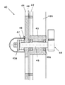
図4は図2のB部拡大図である。この図に示すように、本発明の冷却ガス風路切替え装置40は、固定仕切板42、回転仕切板44及び回転駆動装置46からなる。
固定仕切板42は、冷却室22とガス冷却循環装置24との間を仕切り、その間を遮断している。回転仕切板44は、固定仕切板42の表面に沿ってこの例では冷却ファン24aと同軸に回転駆動装置46により回転駆動される。回転駆動装置46はこの例では、ラックとピニオンであり、回転仕切板44を1/2回転させて上下を逆にするようになっている。ラックの直動には空圧又は液圧シリンダ等を用いることができる。また、本発明はこの構成に限定されず、周知の他の駆動装置を用いることもできる。
【0027】
固定仕切板42の中央部には軸受43aを内蔵する軸受箱43が設けらる。この軸受箱43は、支持フレーム43bにより、真空容器21の循環部21cから支持されている。 回転仕切板44は、中心に回転軸45がキーを回転固定されており、この回転軸45は軸受43aにより冷却ファン24aと同軸に支持れている。圧縮バネ47が、回転軸45の軸端部(図で左端と支持板45a)と回転仕切板44の間に圧縮状態で挟持され、回転仕切板44を常に回転仕切板44に向けて付勢し、その間の隙間を低減するようになっている。このため、付加すれば機能が向上する。
前述の水平仕切板22cの端面と固定仕切板42の端面に、シール材48が張付けられており、回転仕切板44の間、及び回転仕切板44との間の隙間をシールするようになっている。このシール材48は、例えば摩擦の少ない鉛黄銅、グラファイト、等であり、リークを低減しかつ動きを滑らかにしている。
【0028】
図5は図2のC−C線における断面図である。この図において、(A)はC−C線における断面図、すなわち回転仕切板44の正面図であり、(B)は回転仕切板44を除去した断面図、すなわち固定仕切板42の正面図である。
【0029】
固定仕切板42は、ほぼ全面を貫通する開口42aを有する。すなわち、この例では、支持フレーム43bと同位置で半径方向に延びる細長い放射部42bと、最外周、中央部、及び中間部の細いリング状の円形部42cとからなる。なお、この図で中央の円形部42cには、上述した軸受箱43が取付られている。なお、開口42aの位置はこの例に限定されず、可能な範囲で広く設定するのがよい。
【0030】
回転仕切板44は、ガス冷却循環装置の吸込口と吐出口に部分的に連通する吸引開口44aと吐出開口44bを有する。
図5の第1実施形態において、冷却室22は、その内側を上下方向に通過するガス流路を有し、冷却室内22をガスが下方に流れるときに、吸引開口44aが冷却室の下方のみと連通しかつ吐出開口44bが冷却室の上方のみと連通し、冷却室44内をガスが上方に流れるときに、吸引開口44aが冷却室の上方のみと連通しかつ吐出開口44bが冷却室の下方のみと連通するように開口位置が設定されている。
なお、この例において、吸引開口44aはほぼ1/2の円形、吐出開口44bはほぼ1/2の扇形であり、互いに水平軸(前述の水平仕切板22c)に対して反対側に設けられている。
【0031】
この構成により、冷却室22とガス冷却循環装置24との間を仕切る炉体内面積Aのうち、1/2づつをガス冷却循環装置の吸込口と吐出口とし、更に吸込口と吐出口のうち、1/2づつを下方、上方とすることで、吸引開口44aと吐出開口44bを炉体内面積Aの約1/4づつに設定することができる。従って、風路面積を大きくとれ、ガスの通過流速を低減でき、圧損を小さくできる。
また、固定仕切板42とガス冷却循環装置24の間は、内側全面がガス冷却循環装置の吸込口に連通し、外側全面だガス冷却循環装置の吐出口に連通しているので、吐出口/吸込み口の隙間を十分取ることで半面しか開口していなくても反対面への回り込みが可能となり、熱交換器全体を有効利用できる。
【0032】
上述した本発明の構成によれば、冷却室とガス冷却循環装置との間を仕切る固定仕切板の表面に沿って回転仕切板を回転駆動するだけで、冷却室内を通過するガスの方向を交互に切り替えるので、流れ方向に対して回転仕切板が垂直に動く回転駆動であるため、高圧ガス(密度が高いガス体)であっても風圧の影響を受けにくくスムースに風路を切替えることができる。
また、回転仕切板が、ガス冷却循環装置の吸込口と吐出口に部分的に連通する吸引開口と吐出開口を有するので、開口面積の変動や吸込口と吐出口の開口面積差が生じにくく、安定したガス冷却が可能である。また、構造が簡潔であり単一の駆動装置で切替えが可能であり、大きな開口面積を確保できる。
なお、これまでは上下流のガス流れについて実施形態を示したが、回転仕切板を90°回転させて冷却室の整流器を側面(左右)に付けることで、左右流の切替え機構とすることもできる。
【0033】
図6は、本発明の第2実施形態を示す図5と同様の断面図である。この図において、(A)はC−C線における断面図、すなわち回転仕切板44の正面図であり、(B)は回転仕切板44を除去した断面図、すなわち固定仕切板42の正面図である。
この第2実施形態は、冷却室内をガスを上下方向に流すとき(上下流)と、冷却室内をガスを水平方向に流すとき(水平流)の両方に対応できるようになっている。
すなわち、この例において、吸引開口44aはほぼ1/4の円形、吐出開口44bはほぼ1/4の扇形であり、互いに水平軸(前述の水平仕切板22c)に対して反対側に設けられている。
【0034】
この第2実施形態では、冷却室22内をガスが上下方向に流れるときには、図5と同様に、吸引開口44aが冷却室22の下方のみ又は上方のみと選択的に連通し、かつ吐出開口44bが冷却室の上方のみ又は下方のみと選択的に連通するようになっている。また、図6(A)に示すように、冷却室22内をガスが水平方向に流れるときには、吸引開口44aが冷却室のいずれかの片側のみに選択的に連通し、かつ吐出開口44bが冷却室の反対の片側のみと選択的に連通するように開口位置が設定されている。
【0035】
この構成により、冷却室とガス冷却循環装置との間を仕切る固定仕切板の表面に沿って回転仕切板を回転駆動するだけで、冷却室内を通過するガスの方向を上下方向及び左右方向に自由に切り替えることができる。
【0036】
なお、本発明は上述した実施例に限定されず、本発明の要旨を逸脱しない限りで自由に変更することができることは勿論である。例えば、加熱室と冷却室が分離した装置に限らず、加熱と冷却を1室で行える単室炉でも使用は可能である。
【0037】
【発明の効果】
上述したように、本発明の真空熱処理炉の冷却ガス風路切替え装置は、風圧の影響を受けにくくスムースに風路を切替えることができ、開口面積の変動や吸込口と吐出口の開口面積差が生じにくく、安定したガス冷却が可能であり、構造が簡潔であり単一の駆動装置で切替えが可能であり、大きな開口面積を確保できる、等の優れた効果を有する。
【図面の簡単な説明】
【図1】本発明の第1実施形態の冷却ガス風路切替え装置を備えた真空熱処理炉の全体構成図である。
【図2】図1の部分拡大図である。
【図3】図2のA−A線における断面図である。
【図4】図2のB部拡大図である。
【図5】図2のC−C線における断面図である。
【図6】本発明の第2実施形態を示す図5と同様の断面図である。
【図7】非特許文献1に開示された高速循環ガス冷却炉の構成図である。
【図8】特許文献1の「真空炉におけるガス循環冷却促進法」の構成図である。
【符号の説明】
1 被処理品、2 循環ガス、
10 真空加熱炉、11 真空容器、12 加熱室、
13 前扉、14 後扉、15 載置台、16 ヒータ、
20 ガス冷却炉、21 真空容器、
21a 中間断熱扉、21b 容器胴部、
21c 循環部、21e クラッチリング、21d クランプ
22 冷却室、22a,22b 断熱壁、22c 水平仕切板、
24 ガス冷却循環装置、24a 冷却ファン、
24b 冷却ファンモータ、25 熱交換器、
28 整流器、29 補助分配機構、30 移動装置、32 搬送棒、
33 後扉昇降装置、34 前扉昇降装置、
34 中間扉昇降装置、
40 冷却ガス風路切替え装置、
42 固定仕切板、42a 開口、
43 軸受箱、43a 軸受、43b 支持フレーム、
44 回転仕切板、44a 吸引開口、44b 吐出開口、
45 回転軸、46 回転駆動装置(ラックとピニオン)、
47 圧縮バネ、48 シール材[0001]
BACKGROUND OF THE INVENTION
The present invention relates to a cooling gas air path switching device for a vacuum heat treatment furnace.
[0002]
[Prior art]
The vacuum heat treatment furnace is a heat treatment furnace that heats the product to be treated by refilling with an inert gas after decompressing the inside. The vacuum heat treatment furnace is a heat treatment that does not cause coloration due to moisture because the moisture in the furnace and the processed product after gasification is reduced in pressure after reheating and refilling with inert gas etc. can be completely removed. (Referred to as “bright heat treatment”).
[0003]
The gas-cooled vacuum heat treatment furnace has various advantages such as bright heat treatment, no decarburization and carburization, less deformation, and a good working environment. However, the initial gas-cooled vacuum heat treatment furnace has a disadvantage that the cooling rate is insufficient because it is a vacuum cooling type. Therefore, in order to increase the cooling rate, a high-speed circulating gas cooling system has been put into practical use.
[0004]
FIG. 7 is a configuration diagram of the high-speed circulating gas cooling furnace disclosed in Non-Patent Document 1. In this figure, 50 is a heat insulating material, 51 is a heater, 52 is an effective working area, 53 is a furnace body and a water cooling jacket, 54 is a heat exchanger, 55 is a turbo fan, 56 is a motor for a fan, 57 is a cooling door, 58 Is a hearth, 59 is a gas distributor, and 60 is a damper for switching the air path of the cooling gas.
[0005]
In addition, as shown in FIG. 8, the “gas circulation cooling promotion method in a vacuum furnace” of Patent Document 1 includes a
[0006]
[Non-Patent Document 1]
Katsuhiro Yamazaki, Vacuum heat treatment of metal materials (2), Heat treatment No.30, No.2, April 1990 [Patent Document 1]
Japanese Patent Laid-Open No. 5-230528
[Problems to be solved by the invention]
In the high-speed circulating gas cooling furnace described in Non-Patent Document 1 and Patent Document 1 described above, a damper device is normally used as a mechanism for switching an upward and downward air path. However, when the upper and lower damper devices are air path switching mechanisms, there are the following problems.
(1) The damper device has a large load fluctuation due to wind pressure passing at a high speed depending on its opening / closing position. Therefore, in the case of high-pressure gas, it is difficult to move smoothly due to the influence of wind pressure in the damper system.
(2) In the damper device, the opening / closing angle and the opening area are not proportional. Therefore, when switching between the upper and lower drive devices, it is difficult to balance the opening area, the difference between the opening area of the suction port and the discharge port, or the variation becomes large, the amount of cooling gas varies, Stable gas cooling is difficult.
(3) There are a plurality of damper devices at the top and bottom, a plurality of drive devices are required, and the structure becomes complicated.
(4) The opening area is limited by the damper device up and down and is smaller than the furnace body area.
[0008]
The present invention has been developed to solve the above-described problems. In other words, the object of the present invention is to be able to smoothly switch the air path without being affected by the wind pressure, to prevent fluctuations in the opening area and differences in the opening area between the suction port and the discharge port, and stable gas cooling is possible. An object of the present invention is to provide a cooling gas air path switching device for a vacuum heat treatment furnace that has a simple structure, can be switched by a single drive device, and can secure a large opening area.
[0009]
[Means for Solving the Problems]
According to the present invention, the apparatus includes a cooling chamber that surrounds a cooling region in which an object to be processed is placed, and a gas cooling circulation device that cools and circulates gas passing through the cooling chamber, and pressurizes the heated object to be processed. A cooling gas air path switching device for a vacuum heat treatment furnace that cools with a circulating gas, and is driven to rotate along a fixed partition plate that partitions between the cooling chamber and the gas cooling circulation device, and the surface of the fixed partition plate The fixed partition plate has an opening penetrating almost the entire surface, and the rotary partition plate has a suction opening and a discharge opening partially communicating with the suction port and the discharge port of the gas cooling circulation device. Thus, there is provided a cooling gas air path switching device for a vacuum heat treatment furnace, wherein the direction of the gas passing through the cooling chamber is alternately switched.
[0010]
According to the above-described configuration of the present invention, the direction of the gas passing through the cooling chamber is alternately changed only by rotationally driving the rotating partition plate along the surface of the fixed partition plate that partitions the cooling chamber and the gas cooling circulation device. Since the switching is performed by the rotation drive in which the rotating partition plate moves vertically with respect to the flow direction, the air path can be smoothly switched even if it is a high-pressure gas (a gas body having a high density) hardly affected by the wind pressure.
In addition, since the rotary partition plate has a suction opening and a discharge opening partially communicating with the suction port and the discharge port of the gas cooling and circulation device, fluctuations in the opening area and a difference in the opening area between the suction port and the discharge port are unlikely to occur. Stable gas cooling is possible. In addition, the structure is simple and can be switched by a single driving device, and a large opening area can be secured.
[0011]
According to a first preferred embodiment of the present invention, the cooling chamber has a gas flow path that passes through the inside in the vertical direction, and when the gas flows downward in the cooling chamber, the suction opening is below the cooling chamber. And the discharge opening communicates only above the cooling chamber, and when the gas flows upward in the cooling chamber, the suction opening communicates only above the cooling chamber and the discharge opening communicates only below the cooling chamber. The opening position is set so as to.
[0012]
With this configuration, out of the furnace body area A partitioning between the cooling chamber and the gas cooling circulation device, ½ is used as the suction port and the discharge port of the gas cooling circulation device, and among the suction port and the discharge port, 1 By setting / 2 each downward and upward, the suction opening and the discharge opening can be set to about ¼ of the furnace body area A. Therefore, the air passage area can be increased compared to the conventional case, the gas passage flow rate can be reduced, and the pressure loss can be reduced.
Also, between the fixed partition plate and the gas cooling circulation device, the entire inner surface communicates with the suction port of the gas cooling circulation device, and the entire outer surface communicates with the discharge port of the gas cooling circulation device. By taking a sufficient gap, it is possible to wrap around the opposite surface even if only one side is open, and the entire heat exchanger can be used effectively.
[0013]
According to a second preferred embodiment of the present invention, when the gas flows in the vertical direction in the cooling chamber, the suction opening selectively communicates only with the lower side or only the upper side of the cooling chamber, and the discharge opening has the upper side of the cooling chamber. When the gas flows horizontally in the cooling chamber, the suction opening selectively communicates with only one side of the cooling chamber and the discharge opening is opposite to the cooling chamber. The opening position is set so as to selectively communicate with only one side.
[0014]
With this configuration, the direction of the gas passing through the cooling chamber can be freely adjusted in the vertical and horizontal directions by simply rotating the rotating partition plate along the surface of the fixed partition plate that partitions the cooling chamber and the gas cooling circulation device. You can switch to
[0015]
The gas cooling / circulating device includes a cooling fan that is installed adjacent to the cooling chamber and sucks and pressurizes the gas that has passed through the cooling chamber, and a heat exchanger that indirectly cools the gas discharged from the cooling fan.
[0016]
With this configuration, between the fixed partition plate and the gas cooling circulation device, the entire inner surface communicates with the suction port of the gas cooling circulation device, and the entire outer surface communicates with the discharge port of the gas cooling circulation device. By taking a sufficient clearance between the suction ports, even if only one side is open, it is possible to wrap around the opposite side, and the entire heat exchanger can be used effectively.
[0017]
DETAILED DESCRIPTION OF THE INVENTION
Hereinafter, preferred embodiments of the present invention will be described with reference to the drawings. In each figure, common portions are denoted by the same reference numerals, and redundant description is omitted.
[0018]
FIG. 1 is an overall configuration diagram of a vacuum heat treatment furnace including a cooling gas air path switching device according to a first embodiment of the present invention. In this figure, this vacuum heat treatment furnace is a multi-chamber heat treatment furnace provided with a
The
[0019]
The
[0020]
The moving
[0021]
2 is a partially enlarged view of FIG. 1, and FIG. 3 is a cross-sectional view taken along line AA of FIG. As shown in FIGS. 1 to 3, the
The vacuum vessel 21 accommodates an intermediate
[0022]
The cooling
The mounting table 23 is installed at the same height as the mounting table 15 of the
[0023]
The gas
[0024]
The
[0025]
In addition, the high-speed circulating gas-cooled vacuum heat treatment furnace of the present invention is provided with auxiliary distribution mechanisms 29 (for example, blow-in plates) that guide the direction of gas flow flowing in and out of the cooling chamber above and below the cooling
[0026]
FIG. 4 is an enlarged view of a portion B in FIG. As shown in this figure, the cooling gas air
The fixed
[0027]
A
A sealing
[0028]
FIG. 5 is a cross-sectional view taken along the line CC of FIG. In this figure, (A) is a sectional view taken along the line CC, that is, a front view of the
[0029]
The fixed
[0030]
The
In the first embodiment of FIG. 5, the cooling
In this example, the
[0031]
With this configuration, out of the furnace body area A partitioning between the cooling
Further, between the fixed
[0032]
According to the above-described configuration of the present invention, the direction of the gas passing through the cooling chamber is alternated only by rotationally driving the rotating partition plate along the surface of the fixed partition plate that partitions the cooling chamber and the gas cooling circulation device. Therefore, even if it is a high-pressure gas (a high-density gas body), the air path can be smoothly switched without being affected by the wind pressure. .
In addition, since the rotary partition plate has a suction opening and a discharge opening partially communicating with the suction port and the discharge port of the gas cooling and circulation device, fluctuations in the opening area and a difference in the opening area between the suction port and the discharge port are unlikely to occur. Stable gas cooling is possible. In addition, the structure is simple and can be switched by a single driving device, and a large opening area can be secured.
In addition, although embodiment was shown about the upstream and downstream gas flow until now, it can also be set as the switching mechanism of a right-and-left flow by rotating a rotation partition plate 90 degrees and attaching the rectifier of a cooling chamber to a side surface (left and right). it can.
[0033]
FIG. 6 is a cross-sectional view similar to FIG. 5 showing the second embodiment of the present invention. In this figure, (A) is a sectional view taken along the line CC, that is, a front view of the
This second embodiment can handle both when the gas flows in the cooling chamber in the vertical direction (upstream and downstream) and when the gas flows in the cooling chamber in the horizontal direction (horizontal flow).
That is, in this example, the
[0034]
In the second embodiment, when the gas flows in the vertical direction in the cooling
[0035]
With this configuration, the direction of the gas passing through the cooling chamber can be freely adjusted in the vertical and horizontal directions by simply rotating the rotating partition plate along the surface of the fixed partition plate that partitions the cooling chamber and the gas cooling circulation device. You can switch to
[0036]
In addition, this invention is not limited to the Example mentioned above, Of course, unless it deviates from the summary of this invention, it can change freely. For example, the present invention is not limited to an apparatus in which a heating chamber and a cooling chamber are separated, and can be used in a single chamber furnace that can perform heating and cooling in one chamber.
[0037]
【The invention's effect】
As described above, the cooling gas airflow switching device of the vacuum heat treatment furnace of the present invention can be smoothly switched without being affected by the wind pressure, and the opening area varies or the opening area difference between the suction port and the discharge port. This is advantageous in that, for example, a stable gas cooling is possible, the structure is simple, the switching can be performed with a single driving device, and a large opening area can be secured.
[Brief description of the drawings]
FIG. 1 is an overall configuration diagram of a vacuum heat treatment furnace provided with a cooling gas air path switching device according to a first embodiment of the present invention.
FIG. 2 is a partially enlarged view of FIG.
3 is a cross-sectional view taken along line AA in FIG.
4 is an enlarged view of a portion B in FIG. 2. FIG.
5 is a cross-sectional view taken along the line CC in FIG.
FIG. 6 is a cross-sectional view similar to FIG. 5 showing a second embodiment of the present invention.
7 is a configuration diagram of a high-speed circulating gas cooling furnace disclosed in Non-Patent Document 1. FIG.
FIG. 8 is a configuration diagram of “Gas circulation cooling promotion method in a vacuum furnace” disclosed in Patent Document 1;
[Explanation of symbols]
1 Product to be treated, 2 Circulating gas,
10 vacuum heating furnace, 11 vacuum vessel, 12 heating chamber,
13 front door, 14 rear door, 15 mounting table, 16 heater,
20 gas-cooled furnace, 21 vacuum vessel,
21a Intermediate heat insulation door, 21b Container body,
21c Circulation part, 21e Clutch ring,
24 gas cooling circulation device, 24a cooling fan,
24b cooling fan motor, 25 heat exchanger,
28 rectifiers, 29 auxiliary distribution mechanisms, 30 moving devices, 32 transport bars,
33 Rear door lifting device, 34 Front door lifting device,
34 Intermediate door lifting device,
40 Cooling gas air path switching device,
42 fixed partition plate, 42a opening,
43 bearing box, 43a bearing, 43b support frame,
44 rotating partition plate, 44a suction opening, 44b discharge opening,
45 rotation shaft, 46 rotation drive device (rack and pinion),
47 Compression spring, 48 Sealing material
Claims (4)
冷却室とガス冷却循環装置との間を仕切る固定仕切板と、該固定仕切板の表面に沿って回転駆動される回転仕切板とを有し、
固定仕切板はほぼ全面を貫通する開口を有し、回転仕切板は、ガス冷却循環装置の吸込口と吐出口に部分的に連通する吸引開口と吐出開口を有し、これにより冷却室内を通過するガスの方向を交互に切り替える、ことを特徴とする真空熱処理炉の冷却ガス風路切替え装置。A cooling chamber that surrounds a cooling region in which the article to be treated is placed is provided, and a gas cooling circulation device that cools and circulates the gas passing through the cooling chamber, and cools the heated article to be treated with a pressurized circulation gas. A cooling gas air path switching device for a vacuum heat treatment furnace,
A fixed partition plate that partitions between the cooling chamber and the gas cooling circulation device, and a rotary partition plate that is driven to rotate along the surface of the fixed partition plate;
The fixed partition plate has an opening penetrating almost the entire surface, and the rotary partition plate has a suction opening and a discharge opening partially communicating with the suction port and the discharge port of the gas cooling circulation device, thereby passing through the cooling chamber. A cooling gas air path switching device for a vacuum heat treatment furnace, wherein the direction of gas to be switched is switched alternately.
冷却室内をガスが下方に流れるときに、吸引開口が冷却室の下方のみと連通しかつ吐出開口が冷却室の上方のみと連通し、
冷却室内をガスが上方に流れるときに、吸引開口が冷却室の上方のみと連通しかつ吐出開口が冷却室の下方のみと連通するように開口位置が設定されている、ことを特徴とする請求項1に記載の真空熱処理炉の冷却ガス風路切替え装置。The cooling chamber has a gas flow path passing through the inside in the vertical direction,
When the gas flows downward in the cooling chamber, the suction opening communicates only with the lower portion of the cooling chamber and the discharge opening communicates only with the upper portion of the cooling chamber,
The opening position is set such that when the gas flows upward in the cooling chamber, the suction opening communicates only with the upper portion of the cooling chamber and the discharge opening communicates only with the lower portion of the cooling chamber. Item 2. A cooling gas air path switching device for a vacuum heat treatment furnace according to Item 1.
前記冷却室内をガスが水平方向に流れるときに、吸引開口が冷却室のいずれかの片側のみに選択的に連通しかつ吐出開口が冷却室の反対の片側のみと選択的に連通するように開口位置が設定されている、ことを特徴とする請求項1に記載の真空熱処理炉の冷却ガス風路切替え装置。When the gas flows in the vertical direction in the cooling chamber, the suction opening selectively communicates only with the lower side or the upper side of the cooling chamber and the discharge opening selectively communicates only with the upper side or only the lower side of the cooling chamber,
When the gas flows in the cooling chamber in the horizontal direction, the suction opening is selectively communicated with only one side of the cooling chamber, and the discharge opening is selectively communicated with only one side opposite to the cooling chamber. 2. The cooling gas air path switching device for a vacuum heat treatment furnace according to claim 1, wherein the position is set.
Priority Applications (10)
| Application Number | Priority Date | Filing Date | Title |
|---|---|---|---|
| JP2003183968A JP4280981B2 (en) | 2003-06-27 | 2003-06-27 | Cooling gas air path switching device for vacuum heat treatment furnace |
| DE602004027043T DE602004027043D1 (en) | 2003-06-27 | 2004-03-31 | VACUUM HEAT TREATMENT OVEN OF GAS COOLING TYPE AND REFRIGERATOR SENSOR |
| DE602004031061T DE602004031061D1 (en) | 2003-06-27 | 2004-03-31 | Gas cooling type vacuum heat treatment furnace and device for changing the direction of cooling gas |
| EP09008821A EP2116802B1 (en) | 2003-06-27 | 2004-03-31 | Gas cooling type vacuum heat treating furnace and cooling gas direction switching device |
| US10/562,498 US7625204B2 (en) | 2003-06-27 | 2004-03-31 | Gas cooling type vacuum heat treating furnace and cooling gas direction switching device therefor |
| CNB2004800182131A CN100432610C (en) | 2003-06-27 | 2004-03-31 | Gas cooling type vacuum heat treating furnace and cooling gas direction switching device |
| PCT/JP2004/004643 WO2005001360A1 (en) | 2003-06-27 | 2004-03-31 | Gas cooling type vacuum heat treating furnace and cooling gas direction switching device |
| CN2008100831847A CN101294772B (en) | 2003-06-27 | 2004-03-31 | Cooled gas duct changing device for vacuum heat treatment furnace |
| KR1020057024660A KR100943463B1 (en) | 2003-06-27 | 2004-03-31 | Gas cooling type vacuum heat treating furnace and cooling gas direction switching device |
| EP04724762A EP1643199B1 (en) | 2003-06-27 | 2004-03-31 | Gas cooling type vacuum heat treating furnace and cooling gas direction switching device |
Applications Claiming Priority (1)
| Application Number | Priority Date | Filing Date | Title |
|---|---|---|---|
| JP2003183968A JP4280981B2 (en) | 2003-06-27 | 2003-06-27 | Cooling gas air path switching device for vacuum heat treatment furnace |
Publications (2)
| Publication Number | Publication Date |
|---|---|
| JP2005016861A true JP2005016861A (en) | 2005-01-20 |
| JP4280981B2 JP4280981B2 (en) | 2009-06-17 |
Family
ID=34183879
Family Applications (1)
| Application Number | Title | Priority Date | Filing Date |
|---|---|---|---|
| JP2003183968A Expired - Lifetime JP4280981B2 (en) | 2003-06-27 | 2003-06-27 | Cooling gas air path switching device for vacuum heat treatment furnace |
Country Status (2)
| Country | Link |
|---|---|
| JP (1) | JP4280981B2 (en) |
| CN (2) | CN100432610C (en) |
Cited By (7)
| Publication number | Priority date | Publication date | Assignee | Title |
|---|---|---|---|---|
| JP2010035362A (en) * | 2008-07-30 | 2010-02-12 | Mitsui Miike Mach Co Ltd | Electric motor for cooling fan of vacuum furnace |
| WO2010057668A1 (en) * | 2008-11-23 | 2010-05-27 | Dieffenbacher Gmbh + Co. Kg | Method for regulating the temperature of a hot isostatic press, and hot isostatic press |
| WO2011136032A1 (en) * | 2010-04-27 | 2011-11-03 | 株式会社Ihi | Airflow distribution method of single-chamber vacuum furnace |
| CN103162538A (en) * | 2013-03-22 | 2013-06-19 | 浙江固驰电子有限公司 | Rectifier bridge module sintering device |
| US8695494B2 (en) | 2007-05-22 | 2014-04-15 | Cremer Thermoprozessanlagen Gmbh | Method for rapid cooling of a hot isostatic press and a hot isostatic press |
| US8734147B2 (en) | 2006-04-06 | 2014-05-27 | Ihi Corporation | Seal structure for pressurized container, cooling treatment apparatus, multi-chamber heat treatment apparatus, pressure regulating method, and operating method |
| JP2018059208A (en) * | 2015-09-11 | 2018-04-12 | 光洋サーモシステム株式会社 | Heat treatment apparatus |
Families Citing this family (13)
| Publication number | Priority date | Publication date | Assignee | Title |
|---|---|---|---|---|
| JP4458079B2 (en) | 2006-09-27 | 2010-04-28 | 株式会社Ihi | Vacuum carburizing equipment |
| JP4458107B2 (en) | 2007-03-09 | 2010-04-28 | 株式会社Ihi | Vacuum carburizing method and vacuum carburizing apparatus |
| CN100591778C (en) * | 2007-09-07 | 2010-02-24 | 上海中加电炉有限公司 | Heated air circulation bake oven |
| JP5779087B2 (en) * | 2011-12-28 | 2015-09-16 | 株式会社Ihi | Vacuum heat treatment equipment |
| JP6596703B2 (en) * | 2015-03-04 | 2019-10-30 | 株式会社Ihi | Multi-chamber heat treatment equipment |
| CN107614709B (en) * | 2015-05-26 | 2020-02-18 | 株式会社Ihi | Heat treatment apparatus |
| DE102015011504A1 (en) * | 2015-09-09 | 2017-03-09 | Ipsen International Gmbh | Apparatus for treating metallic workpieces with cooling gas |
| KR101909794B1 (en) * | 2016-12-29 | 2018-10-18 | 정원기 | Quenching apparatus |
| JP6938402B2 (en) * | 2018-02-22 | 2021-09-22 | 光洋サーモシステム株式会社 | Heat treatment equipment |
| JP7073016B2 (en) * | 2020-01-10 | 2022-05-23 | 中外炉工業株式会社 | Clean heat treatment equipment |
| CN113446842B (en) * | 2021-05-08 | 2023-08-29 | 滁州华海中谊工业炉有限公司 | High-pressure high-flow-rate air-cooled vacuum furnace |
| KR102551053B1 (en) * | 2021-05-12 | 2023-07-05 | 주식회사 한국제이텍트써모시스템 | Heater unit of heat treatment oven |
| CN113701501A (en) * | 2021-09-02 | 2021-11-26 | 宁波恒普真空科技股份有限公司 | Sintering furnace cooling system |
Family Cites Families (8)
| Publication number | Priority date | Publication date | Assignee | Title |
|---|---|---|---|---|
| JPH0672744B2 (en) * | 1986-08-15 | 1994-09-14 | 石川島播磨重工業株式会社 | Sintering furnace |
| DE3736502C1 (en) * | 1987-10-28 | 1988-06-09 | Degussa | Vacuum furnace for the heat treatment of metallic workpieces |
| JP2510035Y2 (en) * | 1991-02-22 | 1996-09-11 | 石川島播磨重工業株式会社 | Heat treatment furnace |
| JP3116334B2 (en) * | 1991-06-22 | 2000-12-11 | 大同特殊鋼株式会社 | Heat treatment equipment |
| JPH05230528A (en) * | 1992-02-24 | 1993-09-07 | Daido Steel Co Ltd | Method for accelerating gas circulation cooling in vacuum furnace |
| JPH11153386A (en) * | 1997-11-25 | 1999-06-08 | Ishikawajima Harima Heavy Ind Co Ltd | Multichamber multi-cooling vacuum furnace |
| JP5107489B2 (en) * | 2001-05-14 | 2012-12-26 | 中外炉工業株式会社 | Gas-cooled single-chamber heat treatment furnace |
| TW544470B (en) * | 2001-02-22 | 2003-08-01 | Chugai Ro Kogyo Kaisha Ltd | A gas-cooled single-chamber type heat-treating furnace and a gas cooling process in the furnace |
-
2003
- 2003-06-27 JP JP2003183968A patent/JP4280981B2/en not_active Expired - Lifetime
-
2004
- 2004-03-31 CN CNB2004800182131A patent/CN100432610C/en not_active Expired - Fee Related
- 2004-03-31 CN CN2008100831847A patent/CN101294772B/en not_active Expired - Fee Related
Cited By (7)
| Publication number | Priority date | Publication date | Assignee | Title |
|---|---|---|---|---|
| US8734147B2 (en) | 2006-04-06 | 2014-05-27 | Ihi Corporation | Seal structure for pressurized container, cooling treatment apparatus, multi-chamber heat treatment apparatus, pressure regulating method, and operating method |
| US8695494B2 (en) | 2007-05-22 | 2014-04-15 | Cremer Thermoprozessanlagen Gmbh | Method for rapid cooling of a hot isostatic press and a hot isostatic press |
| JP2010035362A (en) * | 2008-07-30 | 2010-02-12 | Mitsui Miike Mach Co Ltd | Electric motor for cooling fan of vacuum furnace |
| WO2010057668A1 (en) * | 2008-11-23 | 2010-05-27 | Dieffenbacher Gmbh + Co. Kg | Method for regulating the temperature of a hot isostatic press, and hot isostatic press |
| WO2011136032A1 (en) * | 2010-04-27 | 2011-11-03 | 株式会社Ihi | Airflow distribution method of single-chamber vacuum furnace |
| CN103162538A (en) * | 2013-03-22 | 2013-06-19 | 浙江固驰电子有限公司 | Rectifier bridge module sintering device |
| JP2018059208A (en) * | 2015-09-11 | 2018-04-12 | 光洋サーモシステム株式会社 | Heat treatment apparatus |
Also Published As
| Publication number | Publication date |
|---|---|
| CN1813163A (en) | 2006-08-02 |
| CN101294772A (en) | 2008-10-29 |
| JP4280981B2 (en) | 2009-06-17 |
| CN100432610C (en) | 2008-11-12 |
| CN101294772B (en) | 2012-07-18 |
Similar Documents
| Publication | Publication Date | Title |
|---|---|---|
| JP4280981B2 (en) | Cooling gas air path switching device for vacuum heat treatment furnace | |
| US7625204B2 (en) | Gas cooling type vacuum heat treating furnace and cooling gas direction switching device therefor | |
| JP4428268B2 (en) | Heat treatment furnace | |
| EP2222428B1 (en) | Hot isostatic pressing arrangement | |
| JPWO2005090616A1 (en) | Two-chamber heat treatment furnace | |
| EP1801529B1 (en) | Change-over apparatus for cooling gas passages in vacuum heat treatment furnace | |
| US20070228596A1 (en) | Hot isostatic pressing method and apparatus | |
| JPS6212288B2 (en) | ||
| JP4441903B2 (en) | High-speed circulating gas-cooled vacuum heat treatment furnace | |
| JPH08199230A (en) | Method and apparatus for cooling workpiece | |
| CN107002159A (en) | Annealing device | |
| JP4779303B2 (en) | Gas cooling furnace | |
| JP7338818B2 (en) | heat treatment furnace | |
| JP2004085126A (en) | Vacuum heat treatment furnace | |
| JP2003171717A (en) | Two-chamber type heat treatment furnace | |
| JPH0210092Y2 (en) | ||
| JP6427949B2 (en) | Vacuum quenching method | |
| JPH0318455A (en) | Melting and casting apparatus | |
| JP2009264691A (en) | Heat treatment device, in line type heat treatment device and manufacturing method of treated object | |
| JPS5839888B2 (en) | Synchronization | |
| JP2000055566A (en) | Cooling device for multi-chamber type heat treatment furnace | |
| JPH0816590B2 (en) | Vacuum sintering furnace | |
| JP2007092137A (en) | Heat treatment apparatus | |
| JP2000130949A (en) | Heat treatment furnace |
Legal Events
| Date | Code | Title | Description |
|---|---|---|---|
| A621 | Written request for application examination |
Free format text: JAPANESE INTERMEDIATE CODE: A621 Effective date: 20060608 |
|
| TRDD | Decision of grant or rejection written | ||
| A01 | Written decision to grant a patent or to grant a registration (utility model) |
Free format text: JAPANESE INTERMEDIATE CODE: A01 Effective date: 20090219 |
|
| A01 | Written decision to grant a patent or to grant a registration (utility model) |
Free format text: JAPANESE INTERMEDIATE CODE: A01 |
|
| A61 | First payment of annual fees (during grant procedure) |
Free format text: JAPANESE INTERMEDIATE CODE: A61 Effective date: 20090304 |
|
| R151 | Written notification of patent or utility model registration |
Ref document number: 4280981 Country of ref document: JP Free format text: JAPANESE INTERMEDIATE CODE: R151 |
|
| FPAY | Renewal fee payment (event date is renewal date of database) |
Free format text: PAYMENT UNTIL: 20120327 Year of fee payment: 3 |
|
| FPAY | Renewal fee payment (event date is renewal date of database) |
Free format text: PAYMENT UNTIL: 20120327 Year of fee payment: 3 |
|
| FPAY | Renewal fee payment (event date is renewal date of database) |
Free format text: PAYMENT UNTIL: 20130327 Year of fee payment: 4 |
|
| FPAY | Renewal fee payment (event date is renewal date of database) |
Free format text: PAYMENT UNTIL: 20130327 Year of fee payment: 4 |
|
| FPAY | Renewal fee payment (event date is renewal date of database) |
Free format text: PAYMENT UNTIL: 20140327 Year of fee payment: 5 |
|
| R250 | Receipt of annual fees |
Free format text: JAPANESE INTERMEDIATE CODE: R250 |
|
| R250 | Receipt of annual fees |
Free format text: JAPANESE INTERMEDIATE CODE: R250 |