JP2004520108A - Improved electrical impedance method and device for detecting and diagnosing disease - Google Patents
Improved electrical impedance method and device for detecting and diagnosing disease Download PDFInfo
- Publication number
- JP2004520108A JP2004520108A JP2002553983A JP2002553983A JP2004520108A JP 2004520108 A JP2004520108 A JP 2004520108A JP 2002553983 A JP2002553983 A JP 2002553983A JP 2002553983 A JP2002553983 A JP 2002553983A JP 2004520108 A JP2004520108 A JP 2004520108A
- Authority
- JP
- Japan
- Prior art keywords
- electrode array
- impedance
- connector
- electrode
- pixel
- Prior art date
- Legal status (The legal status is an assumption and is not a legal conclusion. Google has not performed a legal analysis and makes no representation as to the accuracy of the status listed.)
- Pending
Links
Images


Classifications
-
- A—HUMAN NECESSITIES
- A61—MEDICAL OR VETERINARY SCIENCE; HYGIENE
- A61B—DIAGNOSIS; SURGERY; IDENTIFICATION
- A61B5/00—Measuring for diagnostic purposes; Identification of persons
- A61B5/05—Detecting, measuring or recording for diagnosis by means of electric currents or magnetic fields; Measuring using microwaves or radio waves
- A61B5/053—Measuring electrical impedance or conductance of a portion of the body
- A61B5/0536—Impedance imaging, e.g. by tomography
-
- A—HUMAN NECESSITIES
- A61—MEDICAL OR VETERINARY SCIENCE; HYGIENE
- A61B—DIAGNOSIS; SURGERY; IDENTIFICATION
- A61B2562/00—Details of sensors; Constructional details of sensor housings or probes; Accessories for sensors
- A61B2562/04—Arrangements of multiple sensors of the same type
- A61B2562/046—Arrangements of multiple sensors of the same type in a matrix array
-
- A—HUMAN NECESSITIES
- A61—MEDICAL OR VETERINARY SCIENCE; HYGIENE
- A61B—DIAGNOSIS; SURGERY; IDENTIFICATION
- A61B5/00—Measuring for diagnostic purposes; Identification of persons
- A61B5/24—Detecting, measuring or recording bioelectric or biomagnetic signals of the body or parts thereof
- A61B5/25—Bioelectric electrodes therefor
- A61B5/279—Bioelectric electrodes therefor specially adapted for particular uses
- A61B5/28—Bioelectric electrodes therefor specially adapted for particular uses for electrocardiography [ECG]
- A61B5/282—Holders for multiple electrodes
Abstract
Description
【技術分野】
【0001】
本発明は、複数の電気インピーダンス測定値の使用による生体の疾患状態を検査及び診断するための改善された方法及び装置に関する。
【背景技術】
【0002】
体内の疾患状態を検査及び診断するための方法は、身体組織の物理的性質または生理学的属性の検知及び、これに続く、それらの性質または属性における変化による正常状態と異常状態との弁別に基づく。例えば、X線法は組織の物理的密度を測定し、超音波は音響的密度を測定し、熱検知法は組織熱における差を測定する。測定可能な別の組織特性は電気インピーダンス、すなわち、組織を通って流れる電流に対して組織が与える抵抗である。様々な身体組織の電気インピーダンス値は、健康な人間についての研究により、あるいは外科治療処置後に利用できた切除組織から周知である。さらに、組織に癌性変化が生じると電気インピーダンスの低下がおこることが文献で十分に裏付けられている。この知見は、例えばヒトの乳房癌を含む、多くの動物種及び組織タイプにわたって一貫している。
【0003】
これまで、例えば特許文献1のような、電気インピーダンス画像化を用いて乳房腫瘍を検出しようとする報告が数多くなされている。しかし、インピーダンスデータから画像を構成しようとするときには、基本的な難点がある。電流が直線または単一平面に沿って流れることはない。電流は最小抵抗経路にしたがい、最小抵抗経路は必然的に不規則であり、3次元である。この結果、インピーダンス画像を構成するための演算は非常に複雑であり、画像の忠実度及び解像度を大きく低下させる単純化仮定が必要である。
【0004】
しかし、癌は、検出されるために“見られる”必要はない。癌の存在は癌にともなうマーカ、この場合は電気インピーダンスの変化、及びマーカに敏感な手法により検出することができる。
【0005】
電気インピーダンスを用いる身体内の疾患状態のスクリ−ニング及び診断のための一手法が特許文献2に開示されている。特許文献2によれば、データが、その内の1つは疾患に冒されているかもしれない、2つの解剖学的に相同の身体領域からの編成されたパターンで得られる。そのようにして得られたデータの部分集合が、データ値をn×n行列の要素として構成することにより、処理され、解析される。行列の特徴はさらに、行列の固有値及び固有ベクトルにより決定することができる。これらの行列及び/または行列の固有値及び固有ベクトルは、既知の正常または疾患の行列または固有値及び固有ベクトルのパターンとの一致を調べるために、パターン認識処理にかけることができる。相同身体領域のそれぞれから得られた行列及び/または行列の固有値及び固有ベクトルのそれぞれを様々な解析法を用いて互いに比較し、次いで、正常状態と疾患状態とを弁別するために確立された規準と対照することができる。
【特許文献1】米国特許第4486835号明細書
【特許文献2】米国特許第6122544号明細書
【発明の開示】
【発明が解決しようとする課題】
【0006】
電気インピーダンス法による疾患状態の検出及び診断の能力を改善する。
【課題を解決するための手段】
【0007】
本発明は、複数の電気インピーダンス測定値の使用による生体の疾患状態を検出及び診断するための改善された方法及び装置に向けられる。本発明はいかなる2つの相同身体領域にも適用できるが、論じられる用途は、乳房の異状の、特に良性腫瘍及び悪性腫瘍の有無についての精査である。いずれか特定の理論に束縛されるつもりはないが、本発明の方法は以下の仮定及び仮説を基にすることができる:
1.1つまたは複数の腫瘍は右乳房または左乳房のいずれか一方だけに生じるか、両方に生じる場合は、相異なる相同位置に生じるであろう;
2.右乳房及び左乳房は構造的に同等であり、したがってそれぞれのインピーダンス特性に関してほぼ鏡像(相同)になると考えることができる;
3.(本出願ではインピーダンススキャンと呼ばれる)インピーダンス測定が乳房にかけて多数の方向または経路でなされる場合には、腫瘍に変わる前の正常な組織よりかなり低いインピーダンスを有することが知られている腫瘍の存在が、少なくともいくつかの電流経路においてインピーダンスを歪ませるかまたは変えるであろう;
4.悪性腫瘍に対するインピーダンスの低下量は良性腫瘍に対する低下量より大きく、悪性腫瘍と良性腫瘍を弁別するための方法を提供する;及び
5.正常な個人において右乳房と左乳房との間にはいくらかのインピーダンス差が必ず存在するであろうが、そのような差は癌が存在する場合の差よりも小さいであろう。
【0008】
本発明の方法は、本発明の特別な要件に対して開発されたデータ収集及び解析装置により実施される。乳房表面へのアレイの優れた従形性及び電極の精確な位置決めを可能にする設計及び構成の、改善された乳房電極アレイも提供される。これにより、第1の身体部分からインピーダンス測定値が得られる多数の位置が他方の、相同の、第2の身体部位からインピーダンス測定値が得られる多数の位置に可能な限り精確に対応することが保証される。本装置は、非常に多くの電極組合せからの迅速で正確なインピーダンス測定値並びに事実上即時のデータ解析及び表示を提供する、数多くの新機軸を有する。インピーダンスデータは、その内の1つは疾患に冒されているかもしれない、2つの解剖学的に相同の身体領域からの編成されたパターンで得られる。
【0009】
本発明の一実施形態では、得られるインピーダンスデータがn×nインピーダンス行列の要素を表すと見なされ得るように、電極が選ばれる。次いで、それぞれから診断用計量を得るために、2つの行列の差が計算される。1つでは、要素毎に、相同の右乳房と左乳房の行列の絶対差が計算される。第2では、相対行列要素差が計算されることを除いて、同じ手順が繰り返される。
【0010】
本発明の別の実施形態では、疾患の存在の指標として、あるいは特定の乳房四分円または扇形セクターへの疾患の位置局限に、役立ち得る、計量の計算を可能にする様々な手段で、2つの身体部位において対応するインピーダンス読み値間の差が比較される。インピーダンス差は、本開示においては乳房前面を表す円ピクセルプロットで表示されるが、同じかまたは別の面における別の形状のプロットも、電極の形状寸法及び配置を適切に選択することで有効につくることができよう。一般に正常な状況下では、相同な2つの身体部位においては電流経路が実質的に同じであると考えることができるから、インピーダンス差の使用により、不規則で3次元の電流経路で生じる輻輳した大量のインピーダンスデータが消去される。残りの差は疾患状態によるものと見なされ、解析する上ではるかに取り扱いやすい。
【0011】
説明される本発明の例は新規の改善された方法及び、乳癌を検出し、位置を特定するための装置であるが、本発明は疾患または状態の結果として弁別し得る電気インピーダンスの差が組織にある、その他の疾患または状態にも適用することができる。本発明は、疾患または状態がある領域の電気インピーダンスを本質的に同等の正常な身体領域と比較することができるいかなる身体領域、例えば右及び左前腕、右及び左大腿または右及び左腓における、疾患または状態も検出し、その位置を特定するために用いることもできる。さらに、本発明は、疾患または状態がある領域の電気インピーダンスを、完全には同等ではないが、一貫して変わることのない違いがある別の正常な身体領域と比較することができる身体のいかなる領域、例えば右及び左腹部における、疾患または状態を検出し、その位置を特定するために用いることができる。言い換えれば、比較される2つの領域の間の差は健康な個人では既知で一定であり、したがって、比較を行う際に消去することができる。
【0012】
特に、本発明は生体における疾患状態の存在を診断するための電極アレイを提供し、電極アレイは、可撓体、可撓体から延在する複数の可撓アーム及び複数の可撓アームに設けられた複数の電極を備え、電極はそれぞれの電極間の電気インピーダンス測定値が得られるようにアーム上に配置される。好ましい実施形態において、複数の可撓アームは可撓体の周りに間隔をおいて配置され、電極対が設けられる。
【0013】
さらに、電極アレイの可撓体には、診断されている生体の組織の平らにされる部位に適合された補剛部材を備えることができる。本発明の好ましい実施形態において、補剛部材はリングの形態にあり、皮膚への固定のための粘着材が付けられている。
【0014】
さらに、電極アレイの電極のそれぞれに皮膚への固定のための粘着材を付けることができる。好ましい実施形態において、粘着材はヒドロゲルである。別の実施形態において、粘着材はゲルフォームパッドであり、特にヒドロゲルで満たさるウエルの形態にあるゲルフォームパッドである。
【0015】
電極アレイは、少なくともある程度電極を互いに電気的に分離するための、電極間に少なくともある程度延在する手段も備えることができる。好ましい実施形態において、前記手段は接地導電路を含む。さらに、複数の電極は電極対を含むことができ、それぞれの電極対は電流電極及び電圧電極を有する。本実施形態において、接地導電路は電流電極と電圧電極との間に少なくともある程度延在する。さらに、それぞれの電極は導電路により随伴端子に接続され、接地導電路はそれぞれの電極の導電路及び随伴端子間に、少なくともある程度導電路及び端子を互いに電気的に分離するために、少なくともある程度延在することができる。
【0016】
複数の電極アレイ素子から電極アレイを形成する方法も開示される。それぞれの電極アレイ素子は、少なくとも1本のアームを有する本体を有し、アームは本体から延びだし、アーム上には少なくとも1つの電極が設けられる。本方法は:
a) 電極アレイの主本体を形成するために、複数の電極アレイ素子のそれぞれのアームが互いに間隔をおいた関係をもって主本体から延在するように、複数の電極アレイ素子本体のそれぞれにおいて複数の電極アレイ素子を重ねる工程;及び
b) 複数の電極アレイ素子を合せてクランプする工程;
を含む。
【0017】
それぞれの電極アレイ素子のアームが互いに間隔をおいて電極アレイの主本体の周りに延びだすことを確実にするための位置合せ手段を備えることができる。さらに、複数の電極アレイ素子を合せてクランプするために保持部材が用いられ、保持部材は補剛部材を備えることができる。
【0018】
本発明は、生体のある部位の診断に用いるための電極アレイが電子モジュールに適切に接続されているか否かを確認する方法も提供する。電極アレイは導電路及び導電路を電子モジュールに連結するためのコネクタを備える。本方法は、導電路をコネクタの端子に取り付ける工程、コネクタを用いて電極アレイを電子モジュールに接続する工程、及び導電路がコネクタの端子に適切に接続されているか否かを試験する工程を含む。開示される実施形態では、導電路は接地ループである。
【0019】
本発明は、疾患状態の存在について診断されるべき生体の部位上に電極アレイを位置決めするためのテンプレートも提供する。テンプレートは、複数本の間隔がとられた平行線及び複数本の間隔がとられた平行線上に配置された少なくとも2つの位置合わせマークを有する本体を備える。本体は可撓性で透明な材料からなることができる。さらに、本体は平行線に垂直な方向に細長い形状とすることができ、平行線に垂直な方向に延在する線を少なくとも1本有することができる。テンプレートは平行線に垂直な方向に延在する線上に配置された少なくとも2つの位置合せマークを有することが好ましい。テンプレートの本体は、診断されるべき生体の部位の少なくとも一部を、それを通して目視できる開口を提供することができる。位置合せマークは、開口の周りに間隔をおいて配することができる。
【0020】
テンプレートを用いて生体のある部位上に電極アレイを位置決めする方法も、開示される。本方法は:
a) 診断されるべき部位上またはその近傍で生体に線で印を付ける工程;
b) 診断されるべき部位上に位置決めテンプレートを載せる工程及び間隔をおかれた平行線の内の少なくとも1本を生体上に付けられた線に合せる工程;
c) テンプレートの位置合せマークの位置で生体上に印をつける工程;及び
d) テンプレートによる生体上の印に電極アレイの対応する位置合せマークを合せることにより診断されるべき部位上に電極アレイを位置決めする工程;
を含む。
【0021】
本発明は、電極アレイを電子モジュールに電気的に連結するコネクタに電極アレイを接続するための接続部材も開示する。接続部材は、電極アレイ及びコネクタを受け入れるて互いに対して電気的に接触している状態におくための保持部材並びに、電極アレイ及びコネクタを合せてクランプし、電極アレイとコネクタとの間の電気的接触を確実に保つためのクランプ部材を備える。クランプ部材は電極アレイ及びコネクタに圧縮力を印加するための圧縮部材を含む。保持部材は、台座及び、電極アレイの一部分及びコネクタを嵌め込むことができる、台座から延在する突起を備える。クランプ部材は、保持部材の突起に嵌まり込み、電極アレイ及びコネクタに嵌合するワッシャをさらに備えることができる。保持部材の台座は、ワッシャとは逆の側で電極アレイ及びコネクタと嵌合するための、台座から突き出す少なくとも1本の畝を備えることができる。好ましい実施形態では、突起はねじ溝付管であり、圧縮部材は締付ナットである。さらに、台座は電極アレイ及びコネクタが互いに対して正しい電気的接触状態におかれていることを確実にするための位置合せピンをさらに備えることができる。
【0022】
ワッシャは少なくとも1本の溝を備えることができ、溝は台座から突き出す同心の畝のそれぞれが溝内に嵌まり込むように適合される。開示される一実施形態では、ワッシャに少なくとも2本の溝が設けられ、それぞれの溝は台座から突き出す畝の内の少なくとも1本が溝内に嵌まり込むように適合されている。別の実施形態では、ワッシャに少なくとも2本の間隔がおかれた同心の畝が設けられ、それらの間に、台座から突き出す同心の畝のそれぞれが嵌まり込む。
【0023】
電極アレイを電子モジュールに電気的に連結するコネクタに電極アレイを接続する方法も開示される。本方法は:
a) 電極アレイ及びコネクタを互いに対して電気的に接触している状態におく工程;及び
b) 電極アレイとコネクタとの間の電気的接触を確実に保つために電極アレイとコネクタを合せてクランプする工程;
を含む。
【0024】
さらに、電極アレイの導電路及びコネクタにおける接続数を最小限に抑える方法が開示される。本方法は:
a) 電極アレイ上に複数の間隔をとられた未連結導電面を設ける工程;
b) コネクタ上に複数の間隔をとられた未連結導電面を設ける工程であって、導電面の内の2つが導電路に接続されるべく選ばれる工程;及び
c) 2つの選ばれた導電面の間に連続導電路を形成するように電極アレイの間隔をとられた未連結導電面をコネクタの間隔をとられた未連結導電面に重ねることにより、電極アレイ及びコネクタを互いに対して電気的に接触している状態におく工程;
を含む。
【0025】
好ましい実施形態では、電極アレイ上の間隔をとられた未連結導電面はアレイにより提供される開口の概ね周囲に間隔をおいて配され、コネクタ上の間隔をとられた未連結導電面はコネクタにより提供される同様の開口の周囲に間隔をおいて配される。コネクタの2つの選ばれる導電面は隣り合っており、電極アレイの未連結導電面の間には間隙が設けられていて、コネクタの隣り合う選ばれた導電面に対して間隙が配置されるような重ね合わせの関係に電極アレイとコネクタがおかれたときには、コネクタの選ばれた隣り合う導電面の間を直接に連結する連続経路はない。好ましい実施形態では、電極アレイとコネクタが重なって2つの選ばれた導電面の間に連続導電路を形成することを確実にするために、位置合せ手段が備えられる。さらに、開示される実施形態において、導電路は接地導電路である。
【0026】
さらに、電極アレイの複数の間隔をおかれた未連結導電面とコネクタの複数の間隔をとられた未連結導電面との間の有効な電気的接触を確認するための方法が開示される。本方法は:
a) 2つの選択された導電面の間に連続導電路を形成するように電極アレイの間隔をとられた未連結導電面をコネクタの間隔をとられた未連結導電面と重ね合わせることにより電極アレイとコネクタを互いに対して電気的に接触している状態におく工程;及び
b) 有効な電気的接触が確立されているか否かを見るために2つの選択された導電面の間の導電路にかかる試験信号を測定する工程;
を含む。
【0027】
開示される実施形態では、導電路は接地導電路であり、電気抵抗値が測定されて、有効な電気的接触についてあらかじめ確定された値と比較される。さらに、電極アレイとコネクタを互いに対して電気的に接触している状態におく工程は、電極アレイの電極に対するそれぞれの端子をコネクタのそれぞれの導電面と電気的に接触している状態におく。試験は、それぞれの端子と導電面との間の適切な電気的接触が確立されているか否かを確定する。
【0028】
さらに、本発明はインピーダンス測定値を電極アレイから得て処理するための装置を開示し、本装置は、装置を電極アレイに接続するための手段(例えば、マルチプレクサ)、インピーダンス測定シーケンスを発生するために接続手段を制御するための手段(例えば、マルチプレクサコントローラ)、シーケンス制御手段を制御するためのコンピュータ手段及びインピーダンス測定値及びそのどのような解析結果も表示するためのコンピュータ手段に接続された手段を備える。好ましい実施形態では、装置は、インピーダンス測定シーケンスを発生するための選択パターンを収める少なくとも1つのEEPROMチップ及び一連のインピーダンス測定を通してマルチプレクサをシーケンス制御するためのカウンタをさらに備える。表示手段は、インピーダンス測定値及びその解析結果の目視確認を提供するための表示スクリーンまたはインピーダンス測定値及びその解析結果のハードコピーのためのプリンタを備えることができる。
【0029】
開示される実施形態では、インピーダンス測定値のそれぞれが格子要素として表示される。与えられた格子要素により表されるインピーダンス測定値を得るために用いられた電極アレイの対応する電極を識別するための手段が備えられる。さらに、識別手段は、格子要素で表されるインピーダンス測定値を与えるために用いることができる。加えて、格子要素で表されるインピーダンス測定値があらかじめ定められた期待値に相当していないことを表示するための手段を、表示手段に与えることができる。
【0030】
2つの実質的に同等のマルチプレクサを用いる、本発明のマルチプレクサ試験方法も開示される。本方法はマルチプレクサの内の1つを逆動作させる。本方法は:
a) 2つのマルチプレクサの出力のそれぞれを互いに接続する工程;
b) 逆動作マルチプレクサの入力に較正負荷を与える工程;
c) 同等の出力選択シーケンスにより2つのマルチプレクサの動作を同時に制御する工程;及び
d) 正動作マルチプレクサの入力を通して較正負荷を測定する工程;
を含む。
【0031】
詳しくは、較正負荷の測定はインピーダンス測定である。
【0032】
本発明は生体の実質的に同様の第1及び第2の部位の内の1つにおける疾患状態の可能性を診断するための多くの方法も提供する。一方法は:
a) 第1の集合及び第2の集合のインピーダンス測定値をつくるためにそれぞれの部位のあらかじめ定められた部分にかけて複数のインピーダンス値を得る工程であって、第1の集合は第1の部位についての集合であり、第2の集合は第2の部位についての集合であり、インピーダンス測定値がそれぞれの部位の対応する部分にかけてとられたときに、第1の集合の測定値のそれぞれに対応する測定値が第2の集合にある工程;
b) 平均インピーダンス値が小さい方の集合を識別する工程;
c) 平均インピーダンス値が小さい方の集合のそれぞれの測定値を他方の集合の対応する測定値から差し引くことにより絶対差集合をつくる工程;及び
d) 疾患状態の可能性を診断するために絶対差集合を解析する工程;
を含む。
【0033】
開示される実施形態では、第1及び第2の集合のそれぞれはそれぞれの数学的行列に配列され、絶対差集合は絶対差行列である。絶対差行列は、疾患状態の可能性を診断するためにあらかじめ確立された閾値と比較される行列ノルムを計算するために用いることができる。絶対差行列は、疾患状態の可能性を診断するためにあらかじめ確立された閾値と比較される行列式を計算するために用いることもできる。さらに、絶対差行列の要素の全ての総和を計算し、疾患状態の可能性を診断するためにあらかじめ確立された閾値と比較することができる。
【0034】
疾患状態の可能性及びその位置を診断するための視覚表示を、絶対差行列のそれぞれの列の値の総和を得て、次にそれらの総和をグラフに、例えば2次元グラフにおける棒の高さとして表すことにより、提供することもできる。絶対差行列のそれぞれの要素の値を行列における値の位置の関数としてプロットすることにより、疾患状態の可能性及びその位置を診断するための別の視覚表示を得ることができる。そのようなプロットは3次元グラフとすることができる。
【0035】
生体の第1及び第2の実質的に同様の部位の1つにおける疾患状態の可能性を診断する別の方法は:
a) インピーダンス測定値の第1の集合及び第2の集合をつくるために、それぞれの部位のあらかじめ定められた部分にかけて複数のインピーダンス測定値を得る工程であって、第1の集合は第1の部位についての集合であり、第2の集合は第2の部位についての集合であり、インピーダンス測定値がそれぞれの部位の対応する部分にかけてとられたときに、第1の集合の測定値のそれぞれに対応する測定値が第2の集合にある工程;
b) 第1の集合からのそれぞれの測定値の第2の集合の対応する測定値との間の相対差を計算することにより、相対差集合をつくる工程;及び
c) 疾患状態の可能性を診断するために相対差集合を解析する工程;
を含む。
【0036】
この場合も、第1及び第2の集合のそれぞれはそれぞれの数学的行列に配列することができ、相対差集合は相対差行列である。相対差行列は、疾患状態の可能性を診断するために絶対差行列と同様の態様で用いることができる。
【0037】
別の方法は:
a) インピーダンス測定値の第1の集合及び第2の集合をつくるために、それぞれの部位のあらかじめ定められた部分にかけて複数のインピーダンス測定値を得る工程であって、第1の集合は第1の部位についての集合であり、第2の集合は第2の部位についての集合であり、インピーダンス測定値がそれぞれの部位の対応する部分にかけてとられたときに、第1の集合の測定値のそれぞれに対応する測定値が第2の集合にある工程;
b) 第1及び第2の集合からの最小インピーダンス測定値をそれぞれの集合の最大インピーダンス測定値から差し引くことにより、インピーダンス範囲を計算する工程;
c) インピーダンス範囲を複数のより狭い範囲に細分することにより複数の番号付ビンをつくり、次いで複数のより狭い範囲に連続番号を付す工程;
d) 第1及び第2の集合からのインピーダンス値のそれぞれにビン番号を割り当てる工程;
e) 第1及び第2の集合の内の1つからのそれぞれのインピーダンス測定値のビン番号を他方の集合の対応するそれぞれのインピーダンス測定値のビン番号から差し引くことにより、ビン差集合をつくる工程;及び
f) 疾患状態の可能性を診断するためにビン差集合を解析する工程;
を含む。
【0038】
本方法では、ビン差集合のビン差値の全ての総和が計算されて、疾患状態の可能性を診断するためのあらかじめ確定された閾値と比較される。
【0039】
同様の方法は:
a) インピーダンス測定値の第1の集合及び第2の集合をつくるために、それぞれの部位のあらかじめ定められた部分にかけて複数のインピーダンス測定値を得る工程であって、第1の集合は第1の部位についての集合であり、第2の集合は第2の部位についての集合であり、インピーダンス測定値がそれぞれの部位の対応する部分にかけてとられたときに、第1の集合の測定値のそれぞれに対応する測定値が第2の集合にある工程;
b) 第1の集合の最大インピーダンス測定値から最小インピーダンス測定値を差し引くことにより、第1の集合に対する第1のインピーダンス範囲を計算する工程及び第2の集合の最大インピーダンス測定値から最小インピーダンス測定値を差し引くことにより、第2の集合に対する第2のインピーダンス範囲を計算する工程;
c) 第1のインピーダンス範囲を複数の第1のより狭い範囲に細分することにより複数の第1の番号付ビンをつくり、複数の第1のより狭い範囲に連続番号を付す工程、及び第2のインピーダンス範囲を複数の第2のより狭い範囲に細分することにより複数の第2の番号付ビンをつくり、次いで複数の第2のより狭い範囲に連続番号を付す工程;
d) 第1の集合からのインピーダンス測定値のそれぞれに第1のビン番号の1つを割り当てる工程及び第2の集合からのインピーダンス測定値のそれぞれに第2のビン番号の1つを割り当てる工程;
e) 第1及び第2の集合の内の1つからのインピーダンス測定値のそれぞれのビン番号を他方の集合の対応するインピーダンス測定値のそれぞれのビン番号から差し引くことによりビン差集合をつくる工程;及び
f) 疾患状態の可能性を診断するためにビン差集合を解析する工程;
を含む。
【0040】
開示される実施形態では、ビン差集合のビン差値の全ての総和が計算されて、疾患状態の可能性を診断するためのあらかじめ確定された閾値と比較される。
【0041】
生体の第1及び第2の実質的に同様な部位の1つにおける疾患状態の可能性を診断するまた別の方法は:
a) インピーダンス測定値の第1の集合及び第2の集合をつくるために、それぞれの部位を取り囲むあらかじめ定められた複数の点の間でとられた複数のインピーダンス測定値を得る工程であって、第1の集合は第1の部位についての集合であり、第2の集合は第2の部位についての集合であり、インピーダンス測定値が対応する複数の点の間でとられたときに、第1の集合の測定値のそれぞれに対応する測定値が第2の集合にある工程;
b) 第1及び第2の集合からのインピーダンス測定値のそれぞれにビン番号を割り当てる工程;
c) 複数の点をそれぞれの部位に対する部位を取り囲む経路上のノードとし、複数の点の間でとられたインピーダンス測定値をそれぞれのノード間に延在する弦としてグラフィック表示することによりそれぞれの部位に対するビン弦図をつくる工程;
d) それぞれの部位を取り囲むグラフィック表示のそれぞれを扇形セクタに分割する工程;及び
e) 疾患状態の可能性を診断するために、扇形セクタ内の与えられたノードに収束するビン弦を解析する工程;
を含む。
【0042】
開示される実施形態では、それぞれの扇形セクタが、それぞれの扇形セクタ内に含まれるノードの全てに収束するビン弦の総数をグラフィック表示する。さらに、好ましい実施形態では、それぞれの部位に対して対応するビン弦間の差がより小さいビン番号を有する部位に対するグラフィック表示上のビン差弦としてプロットされる。次いで与えられたノードに収束するビン差弦の数の計算値に、第1の集合からのビン番号と第2の集合からの対応するビン番号との間の差に依存する重みが付けられる。
【0043】
生体の第1及び第2の実質的に同様の部位の内の1つにおける疾患状態の可能性を診断するまた別の方法は:
a) インピーダンス測定値の第1の集合及び第2の集合をつくるために、それぞれの部位を取り囲むあらかじめ定められた複数の点の間でとられた複数のインピーダンス測定値を得る工程であって、第1の集合は第1の部位についての集合であり、第2の集合は第2の部位についての集合であり、インピーダンス測定値が対応する複数の点の間でとられたときに、第1の集合の測定値のそれぞれに対応する測定値が第2の集合にある工程;
b) 複数の点の間でとられたインピーダンス値により作られた弦プロットからピクセル格子をつくる工程;及び
c) 疾患状態の可能性を診断するためにピクセル格子を解析する工程;
を含む。
【0044】
本方法のため、ピクセル格子におけるピクセル強度が、そのピクセルを通過する弦から、すなわち、そのピクセルを通過する弦の本数、そのピクセルを通過する弦線分の長さ及びそのピクセルを通過する弦のインピーダンス値により決定される。ピクセル強度は、様々なピクセルを通過し得る弦の本数及びピクセルを通過する弦線分の長さの差を補償するために、等化することができる。等化してしまえば、ピクセル強度はインピーダンス値だけを示す。
【0045】
さらに、第1及び第2の集合の内の1つからのピクセルインピーダンス値を他方の集合の対応するそれぞれのピクセルのインピーダンス値から差し引くことによりピクセル差集合をつくることができる。本方法では、ピクセル差集合の差値の全ての総和が計算され、疾患状態の可能性を診断するためのあらかじめ確定された閾値と比較される。
【0046】
ピクセル強度は視覚表示され、視覚表示は、様々なインピーダンス値を表わす複数のレベルを表示するように、コンピュータで生成することができる。好ましい実施形態では、コンピュータで生成される視覚表示は様々なインピーダンス値を表わすための256の強度レベルを有する。
【0047】
ピクセル格子は、第1の部位及び第2の部位の複数の点の間でとられた対応するインピーダンスピクセル測定値の間の差をとることにより導かれる、ピクセル代数差プロットとすることができる。さらに、ピクセル格子は、第1及び第2の部位の複数の点からの対応するインピーダンスピクセル間の相対差を計算することにより導かれる、ピクセル相対差プロットとすることができる。
【0048】
さらに、ピクセル代数差プロットに対して、またはピクセル相対差プロットに対して、ピクセルインピーダンス強度の範囲を、代数差プロットについて、及び相対差プロットについて導かれた、スケールファクターを用いてスケールを変更することができ、それぞれのタイプのプロットに対するスケールファクターは、最大ピクセル差が見られた被験者に適用されたときに最大ピクセル強度レベルが256になるように、あらかじめ確定されている。
【0049】
さらにまた、ピクセル代数差プロットに対しても、ピクセル相対差プロットに対しても、ピクセル格子を複数の扇形セクターに分割し、複数の扇形セクターのそれぞれについて、それぞれの扇形セクター内にある全てのピクセルに対するインピーダンス値の総和がグラフィック表示される。
【発明を実施するための最良の形態】
【0050】
ここで、本発明のよりよい理解のため及び本発明がどのように実施され得るかをより明確に示すために、本発明の好ましい実施形態を示す添付図面を、例として、参照する。
【0051】
電気インピーダンス及び4電極測定法
電気インピーダンスは、図1に示されるような4電極を用いて測定される。外側対電極1は電流Iの印加のために用いられ、内側対電極2は、電流により組織3のような材料にかけて生じる電圧Vを測定するために用いられる。電極1の間を流れる電流Iは矢印4で示される。インピーダンスZは、VのIに対する比、すなわち:
【数1】

である。電流注入及び電圧測定に対して独立の電極対を用いることにより、電圧測定電極における偏倚効果が最小限に抑えられ、より正確なインピーダンス測定値を得ることができる。
【0053】
インピーダンスは、抵抗及び容量性リアクタンス(あるいは、等価的に、インピーダンスの大きさ及び位相角)の、2つの成分からなる。本発明では、いずれの成分も測定され、表示され、解析される。しかし、本発明の説明のため、抵抗成分だけを用い、互換的に、抵抗またはより普遍的な名辞のインピーダンスと称することとする。
【0054】
乳房電極アレイ
図2は、16対の電極を有し、それぞれの電極対が電流注入のための外側電極8及び電圧測定のための内側電極9からなる、本発明の乳房電極アレイ5を開示する。図を簡単にするため、導電経路及び電気コネクタは示されていない。図示されるアレイの実施形態は主部6及び尾部7を有する。円形に配置された16対の矩形電極が示されるが、本発明とともに有利に用いられ得る多くの代替形態;より多いか少ない電極対;様々な電極形状及び寸法;アレイの主部及び尾部の別の形状;及び、電極の別の幾何学的配置、例えば3つまたはそれより多くの電極をもつ放射状扇形セクター、がある。電極配置にかかわらず、それぞれのインピーダンス測定のためには、その間に電流が注入される2つの電極及びその間にかかる電圧が測定される2つの電極の、4つの電極が用いられなければならない。電圧測定電極及び電流注入電極は、図2に示されるように必ず物理的に内側及び外側にある必要はない。
【0055】
電極8及び9は、導電性であり、アレイが皮膚上におかれて皮膚に押し付けられたときに電極の粘着性が良好な皮膚固定を確実にするように、ヒドロゲルのような自然粘着性の材料でつくられる。あるいは、アレイの固定のため、アレイの主部6及び/または尾部7上の様々な位置に粘着性材料を用いることができる。乳房の全領域におけるインピーダンス測定を確実にするため、電極アレイ5は、乳房のカップサイズが異なる女性に使用するための様々な大きさにつくられる。
【0056】
乳房電極アレイ5の裏当て材は、乳房表面形状に追従し、良好な電極接触を確実にするため、あらゆる方向に可撓でなければならない(説明の目的のため、あらゆる方向に可撓な材料は、例えば綿であるが、例えば、一方向に曲げられると直交方向には曲がりにくくなるポリエステルのような材料ではない)。裏当て材は、電極への電気経路を与えるための導電性インクの被着も可能でなければならない。これらの要件の全てを満たす材料の例は、デュポン(Dupont)社のTyvek(登録商標)ポリエチレンファイバである。形状追従性はさらに、切込みすなわちダーツ11により補助される。ダーツ11は主部6の内縁、または外縁あるいは両者の様々な位置に配することができる。
【0057】
図3に示される、可撓性で透明な材料13でつくられた本体を有する位置決めテンプレート12を用いて皮膚上に付けられた位置合せマークに、乳房電極アレイ5の主部6の内縁の4つの位置に示される位置合せマーク10の位置を合わせることにより、両乳房への電極アレイの、より正確で、一貫性のある同等な配置が補助される。これらのマークの配置は、1つの点(乳首の中心)及び1つの角度または等価的に1つの軸(身体の垂直軸)により一意的に識別される。この軸は、被験者が立っているかまたは背を伸ばして座っている間に下げ振り糸を用いて、皮膚上に垂直軸線をマークすることにより識別することができる。テンプレート12は、乳首を中心にして中央孔16をおいて、乳房上に配置される。テンプレートは次いで、線15が身体にマークされた垂直軸に平行になるように、回転される。テンプレートに何本かの線15を設ければ、身体にマークされた垂直軸に最も近い1本またはそれより多くの線15を用いることにより、線15と身体にマークされた垂直軸との垂直位置合せが容易になる。テンプレート12が透明であることから、裏返すことで身体の右側でも左側でもテンプレートを用いることが可能になる。乳房電極アレイ5の位置合せマーク10に正確に対応する、2つが垂直軸14上で、2つが水平軸17上の、4つの小孔18がある。位置決めテンプレート12の孔18を通して、インクマークまたはその他のマークが皮膚表面につけられる。次いでテンプレートが取り外され、電極アレイが、電極アレイの位置合わせマーク10を皮膚上のインクマークに合わせて、貼り付けられる。
【0058】
図4は、図2の乳房電極アレイ5の改変形態である乳房電極アレイ19を開示する。図4は電極リード配線20(導電路)及びコネクタ21の実装形態も示し、コネクタ21は、後に説明される、本発明のフロントエンド電子モジュールに取り付けられるケーブルに挿入するためのものである。乳房電極アレイ5のダーツ11が乳房電極アレイ19には示されていないが、図4の乳房電極アレイにもダーツを有益に用いることができる。乳房電極アレイ19の尾部23は、被験者の中心または胸部の中央上部近くにおかれるフロントエンドモジュールのケーブルへの連結を容易にするために、身体の正中線を指して内側に向けるため、図4に示されるように角度をつけることができる。右側アレイ及び左側アレイは、それぞれの尾部23が互いに鏡像である点で異なり、それぞれ身体の正中線に向けて適切に角度がつけられている。
【0059】
乳房電極アレイ19は、電気接地ループ24を形成するための、コネクタ25及び26で終端する、特別の導電路を備える。接地ループ24により、電流注入電極28の電圧測定電極29からの絶縁分離が改善される。さらに、接地ループ24により、右側アレイと左側アレイが正しい側に貼り付けられていることを確認するための電気試験が可能になる。接地ループ24のリムの1つは右乳房用とされるアレイ上ではコネクタ25の端子に接続し、左乳房用とされるアレイ上では、同じリムがコネクタ25から取り外され、使用されていないコネクタ27のうちの1つの端子に接続される。接地ループ24の期待される右側用または左側用の導通に対する試験により、右側アレイ及び左側アレイが識別される。
【0060】
アレイの尾部23は、長くすることも短くすることも、角度をつけることも真直にすることも、様々な形状(例えば砂時計形)をもつこともでき、導電路20の間隔を縮めるかあるいは両面電気コネクタの使用に対応して導電路20を両面印刷することにより幅を狭くすることができる。図2に示されるような乳房電極アレイ5の位置合せマーク10と同等に、位置合せマーク30が用いられる。
【0061】
図5及び5Aは、本発明の、別の、好ましい乳房電極アレイ31を開示する。本体32'の周りで間隔がおかれた、16本のアレイアーム32が示される(図5を参照されたい)。それぞれのアレイアーム32には、電流注入電極33及び電圧測定電極34が設けられる。アーム数を減らしたか、またはアーム数を増やしてアーム幅を狭くした、その他の実施形態もあり得よう。電極アレイ31用の裏当て材35は薄く、一般には約0.005インチ(0.127mm)であり、好ましくは透明であって、一方向に曲げられると他の全ての方向で不撓になる。この材料の表面は、導電性インクで印刷可能でなければならず、ヒドロゲルのような自然粘着性電極材料が着かなければならない。本発明に適するそのような材料の例はポリエステルフィルムである。裏当て材35は、後に説明される、ケーブル保持具62がそれを通して嵌め込まれる中心孔36を有する。乳房電極アレイ31は、中心孔36と同心で、乳房電極アレイ31にとりつけられた、補剛リング37を有する。補剛リング37は、平らで、厚さが約0.06インチ(約1.5mm)であり、16辺のリングである。辺のそれぞれは、アレイアーム32の基部に揃えられる。図示されてはいないが、それぞれのアレイアームの間の鋭角の連結部38は、その点における裏当て材の裂けを防止するために小径の切欠きで優先的に置き換えられている。補剛リング37は、適当な接着剤またはその他の手段を用いて乳房電極アレイ31の被験者の皮膚に向けられることになる側の上に取り付けられる。補剛リング37の自由面には粘着材が塗布され、続いて粘着材塗布面が皮膚に取り付けられることになろう。乳房電極アレイ31上には、多くの位置合せマークが印刷されている。これらのマークは、それぞれの乳房へのアレイの正確な位置合わせを確実にするために、例えば、図3に示され、上で論じられたようなテンプレート12を用いて乳房につけられた消去可能なマークに合わせられる。位置合せマーク39の1つには矢印40が付帯し、矢印40は、矢印40で定められる軸が身体の垂直軸に平行になるべきであることを示す。説明されるような態様で、ケーブル保持具のピンを受け入れるための位置合せ孔41を裏当て材35に設けることもできる。
【0062】
図5Aに示されるように、電流注入電極33及び電圧測定電極34は、導電性インクの基層33'及び導電性粘着層33''の、2つの構成要素からなる。普通の導電性粘着材の1つは、心電図検査法のような用途に用いられる、ヒドロゲルである。硬化するまでは液体であるヒドロゲルは、いくつかの手段で導電性インク電極基層に塗布することができる。一方法は、表面張力特性により、導電性インクに対しては比較的高い親和性をもち、ポリエステルに対しては低い親和性をもつ、ヒドロゲルを用いることである。そうであれば、液体形態で塗布されたヒドロゲルが導電性基層上に均等に広がり、電極の寸法及び形状に正確にしたがうことができるであろう。塗布に続いて、ヒドロゲルを硬化させて、固化させる。別の方法では、寸法及び形状が電極と同じ孔をもつ粘着性ゲルフォームパッドが用いられる。ゲルフォームパッドはポリエステルに貼り付けられ、底が導電層のウエルを形成する。ウエルをヒドロゲルで満たし、次いでヒドロゲルを硬化させる。別の方法では、適切な電極寸法及び形状に切り取られて導電性基層に貼り付けられる、固化し、硬化した、ヒドロゲルシートが用いられる。裏当て材35の皮膚に向けられる腹側とは逆の背側には、図6に示されるように、補剛リング37の(破線で示される)内径47に対応する内円部分を除いて、乳房電極アレイ31の背側を全て覆う、薄く、透明な絶縁層がある。絶縁層は、何があっても被験者の皮膚に接触しないように、導電路を保護する。補剛リング37並びに電極33及び34の粘着面は、使用するときまで、剥離裏地をもつ剥ぎ取り可能なシートで保護される。
【0063】
図6は、乳房電極アレイ31の電気配線の一例を示す。導電路42,43及び44が裏当て材35の被験者の皮膚に向けられない側(背側)の上に印刷される。導電路42及び43はスルーホール(図示せず)を通って裏当て材35の被験者の皮膚に向けられる側(腹側)に延びて、それぞれ、電流注入電極33及び電圧測定電極34の基層を形成する一般には同じ導電性インクとの電気的接続を形成する。
【0064】
導電路42及び43は他端でコネクタタブ45に接続する。16本の接地導電路44もあり、接地導電路44のそれぞれ1本は、電流注入電極33と電圧測定電極34の間及びそれぞれの電極の導電路42と43の間に配置されて、電気的分離を強化し、これらの回路素子間のクロストークを低減する。接地導電路44はコネクタタブ46に接続する。隣り合う2つのコネクタタブ45に接続される隣り合う2本の電流路42,コネクタタブ46に接続される介在接地路44,次いで、隣り合う2つのコネクタタブ45に接続される隣り合う2本の電圧路43という繰返しシーケンスになっており、さらに、どの電流コネクタタブ45と電圧コネクタタブ45との間にも接地路が挿入されていることにより、電流回路側と電圧回路側の間のクロストークがさらに低減されていることに注意されたい。コネクタタブ45の形状が台形であることは、以下の節で説明されるように、特別な機能を果たす。
【0065】
図7Aは、個別のリボン49及び50からなる、可撓性の平リボンケーブル対48を開示し、リボン49及び50のそれぞれには、一端が円形コネクタリング53のコネクタタブ51及び52で終端する、図には示されていない、34本の導電路がある。これらのリングは中心孔54を有し、中心孔54の直径は乳房電極アレイ31の中心孔36の直径と実質的に同じである。リボン49及び50の導電路は他端で標準の2列72ピンコネクタ55の個々の列で終端し、コネクタ55は、続いて、後に説明される、本発明のフロントエンド電子モジュールの接合コネクタに取り付けられる。フレキシブル回路の製造で標準的に行われているように、リボン49及び50はポリイミド材であり、導電路には銅が用いられ、コネクタタブ51及び52はスズ/鉛でメッキされた銅である。リボン49及び50のそれぞれには、標準的な両面態様で印刷された34本の導電路がある。導電路の内の16本が電流注入電極用であり、16本が電圧測定電極用であって、2本の導電路が電気接地に接続されるが、一般には、より多くの接地接続を用いることができよう。リボン49及び50の表面はいずれも、コネクタタブ51の外縁の直径57で定められるコネクタリング53の内側非絶縁部分を除き、薄いポリイミド層で絶縁される。
【0066】
図7Bは、コネクタリング53の電気配線及びリボン49または50の隣接部分の詳細を示す。導電路の両面印刷は、一方の面については実線58で、他方の面については破線59で示される。導電路のそれぞれ1本はそれぞれのコネクタタブ51で終端する。しかし、2つの接続60だけが導電路で接地コネクタタブ52となされ、残る14の接地コネクタタブは以下の節で説明される態様で接続されることになる。図に示されるように、リボン49及び50には、以下で説明されるようにケーブル保持具の位置合せピンを受け入れるための位置合せ孔61も設けることができる。図7Bには2つの位置合せ孔61が示されているが、より多くの位置合せ孔を用いることもできよう。そのような位置合せ孔の位置は、電極アレイの裏返しまたは電極アレイの右と左の入れ違いを検出及び/または防止する方法を提供するためにリボン49と50とで異ならせることができよう。
【0067】
乳房電極アレイ31を可撓リボン49及び50のそれぞれに取り付けるためのコネクタ部材が開示される。コネクタ部材は、電極アレイ及び可撓リボンを受け入れて互いに対して電気的接触状態におくための保持部材並びに、電極アレイと可撓リボンを合わせてクランプして、電極アレイと可撓リボンとの間の電気的接触を確実に保つための、クランプ部材を備える。図8に示される実施形態において、コネクタ部材はケーブル保持具62である。ケーブル保持具62は、台座部品63,ワッシャ64及び締付ナット65の、3つの構成要素を有する。これらの構成要素は、強度、剛性、硬度、寸法安定性及び非導電特性のため、例えばデュポン社のDelrin(登録商標)アセチルコポリマーのような材料から作製される。同様の特性の組合せをもつその他の材料も用いることができよう。台座部品63は平環フランジ66及び、中央にある、中空のねじ溝付円筒管67からなる。環フランジ66は、表面に、同心の2本の畝68及び2本の位置合せピン69を有する。これらのピンは、Delrinのような材料またはステンレス鋼のような金属から作製することができる。台座部品63のさらに詳細が、図8と同じ参照数字が適用されている、図9A-1及び9A-2に示される。特に図9A-2に示されるように、畝68は、図9B-2に示されるワッシャ64の溝70のような、好ましくはテーパ付の、嵌合溝との位置合わせを容易にする、テーパ付側面を有する。
【0068】
ワッシャ64は、図9B-1及び図9B-2に示されるように、2本の円周溝70及び2つの位置合せ孔71を有する。ワッシャ64の別の実施形態は、図9C-1及び図9C-2に示されるワッシャ72である。この実施形態では、ワッシャ72が、ワッシャ72の主本体に溝様構造を形成する2本の円周畝73及び74、並びに2つの位置合せ孔75を有する。図9C-2に示されるように、外周畝73は内周畝74より高い。
【0069】
図8のケーブル保持具62の第3の構成要素は締付ナット65である。締付ナット65は刻み付ノブ76,フランジ77及び内部ネジ溝78を有する。
【0070】
図9Dは、組立て後の、乳房電極アレイ31,可撓リボンケーブル48及びケーブル保持具62を、台座部品63,ワッシャ72及び締付ナット65とともに示す。
【0071】
組立作業においては、乳房電極アレイ31が以下のようにして可撓リボンケーブル対48に連結される。ケーブル保持具62の台座部品63のねじ溝付円筒管67が乳房電極アレイ31の中心孔36にアレイ31の、補剛リング37が取り付けられている側である、腹側から挿入され、台座部品63の位置合せピン69が乳房電極アレイ31の位置合せ孔41を通して挿入される。補剛リング37の乳房の皮膚への接触を確実にするため、台座部品63の環フランジ66の直径は補剛リング37の内径より若干小さく、環フランジ66の厚さは補剛リングの厚さより薄い。この時点で補剛リング37の保護粘着シートを剥ぎ取ることができ、台座部品63を内にもつ乳房電極アレイ31が乳首を中心にして配置される。乳房電極アレイ31が回されて正しい位置につけられてから、補剛リング37が押し付けられて皮膚にしっかりと接触させられる。これは位置合せマーク39の指示矢印40(図5を参照されたい)を頭部を指すように上方に向け、次いで、位置合せマーク39の全てを、図3で説明されたテンプレート12のような位置決めテンプレートを用いて先に付けられた、皮膚マークの上に直接重ねることにより達成される。必要に応じて、乳房電極アレイの可撓リボンケーブルへの組み付けはアレイを乳房に取り付ける前に完了させることができる。
【0072】
次いで、以下の条件:(1)コネクタリング53の露出した電極タブ51及び52が乳房電極アレイ31の電極タブ45及び46に向かい合う;(2)コネクタリング53の位置合せ孔61が台座部品63の位置合せピン69に嵌合する;及び(3)72ピンコネクタ55が被験者の頭部を向くように可撓リボンケーブル48の向きが定められる;が満たされるように、可撓リボンケーブル48のコネクタリング53が台座部品63の円筒管67に滑り嵌めされる。上記の条件を満たすことにより、コネクタリング53の電極タブ51が乳房電極アレイ31の電極タブ45に完全に重ねられることになり、コネクタリング53の台形電極タブ52が乳房電極アレイ31の台形電極タブ46と若干重ねられてスタガー連結連続電気経路が形成されることになろう。本発明のこの態様には2つの特徴がある。第1に、電極タブ46及び52が、図7Bに示される2つの接地接続60の間に連続電気経路を形成するから、2本の接地導電路しか必要ではない。第2に、正しい取付け以外のどのような取付けも連続電気経路に中断(開回路)を生じさせ、さらに、コネクタリング53の電極タブ51が乳房電極アレイ31の電極タブ45と正しく位置合せされていないことも示すであろうから、コネクタリング53の乳房電極アレイ31への適切な取付けの電気試験が提供される。接合電極タブ46及び52の、寸法、形状及び重ね合わせの度合いの選択により、所望の大きさの回転位置合せずれ感度が確立され、これらの電極タブが提供する導電路の抵抗値の測定を位置合せずれの度合い及び接触圧力の指標を得るために用いることもできよう。接地電極タブの失われる接続の数及びパターンを変え、次いで、コネクタリング53及び乳房電極アレイ31上の接地電極タブの正しいスタガー連結回転位置合せを必要とする接地接続回路の確立に依存することにより、上記手法のその他の実施態様が可能である。
【0073】
台座部品63の円筒管67へのコネクタリング63の取付けに続いて、ワッシャ72、次いで締付ナット65が、円筒管72に取り付けられる。ワッシャ72の位置合せ孔71が台座部品63の位置合せピン69に嵌合し、よって嵌合後のワッシャ72の回転が防止されるように、ワッシャ72が回される。さらに、ワッシャ72(またはワッシャ64)は、それだけで、あるいは可撓リボンケーブル48及び乳房電極アレイ31と組み合わされて、図9D及び9Eに示されるように、位置合せピン69の高さと少なくとも同じ高さになっている。次いで、締付ナット65を回して、ワッシャ72をコネクタリング53にしっかりと接触させることができる。このようにして、コネクタリング53の電極タブ51及び52が乳房電極アレイ31の電極タブ45及び46と接触させられる。この接触は、コネクタリング53の可撓ポリイミド材料と乳房電極アレイ31の可撓ポリエステルに対する、それぞれが台座部品63の畝68と、ワッシャ72の相補的な畝73及び74との間に、あるいはワッシャ64の相補的な溝70との間に、クランプされているときの圧縮力の効果により確実に保たれる。圧縮力は可撓性物質を曲げ、台座部品63の畝68が、図9Eに示されるように、円形曲げ梁の支点である皿バネの態様の作用を可撓性物質に生じさせる。この作用により、可撓性物質が圧縮の下で浅い皿形状をとるので、電極タブの所望のこすり付け接触作用も生じる。ワッシャとケーブル保持具62の締付ナットの接触表面は、圧縮の度合いの触覚及び聴覚的案内を提供するために、一方の面上の突起と他方の面上の孔とが符合するか、または両者の面上の突起が食い違いになるような構造にすることができる。突起の孔への嵌め込みまたは表面突起の突き合わせにより、締付ナットの緩みをさらに確実に防止することもできよう。
【0074】
乳房電極アレイ31が正しい向きで可撓リボンケーブル48に連結され、補剛リング37上の粘着材により乳房に取り付けられると、電極33及び34の全ての取付けを正確に、また高い再現性をもって、進めることができる。特に、平らな、補剛リング37の作用は、乳房電極アレイ31が取り付けられた乳房の皮膚を強制的に同じ平らな面にすることである。したがって、補剛リング37の直辺から出ているそれぞれのアレイアーム32は、径方向で外側に向けて緩やかに押されていくと、容易に曲がって乳房表面の輪郭にしたがい、同時に、先に述べたように、ポリエステルフィルムの性質のため、アームは径方向輪郭以外のどの方向に沿っても剛性が高くなり不撓になる。それぞれのアレイアーム32の末端にある自然粘着性電極33または34を(保護シートが剥ぎ取られていれば)正しい径方向位置において皮膚に押し付けて貼り付けることにより、貼付けプロセスが完了する。上記の特徴−補剛リングによる皮膚の平坦化、その周りで可撓である直線軸をもつそれぞれのアレイアームを設けるための多辺補剛リング構造、アレイアームが乳房表面形状にしたがうように原可撓方向におけるアレイ材料の好ましい曲がり及び、逆に、他の全ての方向における高剛性−の全ての複合により、全てが本発明で説明されるような相同電気インピーダンス解析の有意な使用に必要な条件である、一貫した(用いられる例においては等しい)電極間隔及び、再現性が高く正確な、並行電極配置が保証される。
【0075】
図10は乳房電極アレイ79を開示し、この乳房電極アレイ79は、別の電気配線を示す、乳房電極アレイ31の改変態様である。本改変態様では、アレイアームの内の1本が、図4の乳房電極アレイ19と同様の接続尾部80を形成するため、幅が広げられ、延長されている。電流注入電極81及び電圧測定電極82の位置は、本例では、全ての電極の幾何学的パターンを乳房電極アレイ31と同じに保つため、変更されていない。アレイアームの幅を広げることにより、残りの15対の電流注入電極85及び電圧測定電極86のそれぞれからの導電路83及び84が、電極81及び82のための導電路とともに、接続尾部80における経路をとることが可能になる。両面印刷導電路が、一方の面については実線で、他方の面については破線で示されている。導電路は全てコネクタ86で終端し、一般に、乳房電極アレイの正しい右側及び左側配置の確認のための接地コネクタ87の使用のような、図4の尾部23に備わる特徴の全てを、本例にも同等に適用することができる。図示されてはいないが、電流注入回路側と電圧測定回路側の改善された絶縁分離のための接地導電路の使用を、介在導電路及び/または導電インク領域として実施することができよう。
【0076】
図11A及び11Bは、多アーム電極アレイの別の実施方法を開示する。特に図11Aは、基本4アーム電極アレイ88を開示する。基本4アーム電極アレイ88は、薄く透明なポリエステルフィルム上に、通常の、粘着性ヒドロゲル電流注入電極89及び電圧測定電極90を有する。アレイのそれぞれのアーム91は位置合せマーク92及び位置合せ孔93を有する。使用時に乳首が中心におかれる中央穴94がある。図を簡潔にするため、電極配線は示されていない。アームがより少ないか多い、異なる長さのアームが組み合された、及びアームが互いに対して等しくまたは不等に回転されている、その他の基本構成も、様々な寸法及び形状の電極アレイをつくるために用いることができよう。さらに、径方向に、あるいは別の幾何学的配置でインピーダンスを測定するために、それぞれのアーム91に3つまたはそれより多くの電極を配することもできるであろう。
【0077】
図11Bは、4つの4アーム電極アレイ88を集成した、16アーム電極アレイ95の電極側の平面図を示す。電極アレイ88は、アレイ保持具96の(底しか見ることができない)ねじ溝付中空円筒97を穴94に嵌め込み、さらに電極アレイ88を回転させてアレイ保持具96の(底しか見ることができない)位置合せピン96を電極アレイ88の位置合せ孔93に嵌め込むことによりあらかじめ定められた位置に配し、続いて、ねじ溝付中空円筒97にワッシャ及びナットを通してクランプすることにより、結合される。アレイ保持具96の底は、底面が概ね平らで剛性が高く、集成体の皮膚への初期貼付けを提供するための粘着性被覆をもつ点で、補剛リング37と同様である。乳房電極アレイ31の補剛リング37について述べた理由のため、アレイ保持具96は、アレイ保持具96が貼り付けられる皮膚表面を強制的に平らな面にする。乳房上の電極アレイ95の正しい位置は、先に説明したように、位置決めテンプレートにより皮膚上に付けられたインクマークに電極アレイ95の位置合せマーク92を重ねることにより得られる。
【0078】
一般に、本明細書の様々な開示における電極は矩形として描かれ、電極対は並行して配置される。円形、卵形、環状及びC字形を含むがこれらには限定されない様々な形状の電極を備えるその他の多くの構成を有利に用いることができよう。電流注入電極と電圧測定電極とは、同じ形状である必要はなく、同じ寸法である必要も、並行している必要もない。例えば、C字形電圧測定電極及びC字形電圧測定電極の開放端の間に配置された小さい円形の電流注入電極には、寸法及び有効性の面で利点が有り得る。
【0079】
インピーダンスデータ収集
図12は、インピーダンスデータの、自動的な、測定、処理及び解析のためのデータ収集及び解析装置99のブロック図を開示する。図示の目的のため、装置99は、乳癌のスクリーニング、位置決定及び診断のために用いられるとして説明される。しかし、本発明の方法及び装置が他の身体部位におけるスクリーニングまたは診断のため並びにその他の状況及び疾患のために同様の態様で使用され得ることは当然である。本例については、乳房電極アレイ100が、図5の好ましい乳房電極アレイ31のように、16対の電極を有する。先に述べたように、電気インピーダンス(またはその逆数のアドミッタンス)を測定するために4電極法が用いられる。50キロヘルツの定振幅連続正弦波電流Iが電極アレイの外周101にある2つの電流注入電極間に印加され、この結果生じる電圧Vが、電極アレイの内周102にある2つの電圧測定電極間で測定される。電流電極の外周配置及び電圧電極の内周配置は本発明に対して限定的ではなく、その他の多くの電極の配置及び構成を用いることができよう。50キロヘルツ正弦波の使用は多くの生体インピーダンス測定で標準的に行われているが、より広い範囲の使用可能な周波数があり、利用の度合いは少ないが、その他の波形がある。インピーダンスZは:
【数2】
から計算される。後に説明するように、図示される実施形態ではそれぞれの乳房について330個のそのようなインピーダンス値が得られる(スキャンされる)。
【0081】
装置99は、主要コンポーネントとして、フロントエンドモジュール103,及びラップトップPC105を有する。レポート及び結果のハードコピーのためのプリンタ106もある。フロントエンドモジュール103内には、右マルチプレクサ107及び左マルチプレクサ108がある。これらのマルチプレクサは、右及び左乳房電極アレイのそれぞれとの接続を提供する。それぞれの測定に対して、一度に、乳房電極アレイの外周101にある電流注入電極の内の2つへの接続及び同じアレイの内周102にある電圧測定電極の内の2つへの接続の、4つの接続がなされる。現在実施されているように、一方の側について330回の測定の全てが完了してから他方の側についての測定プロセスが始まる。一度に一方の側だけが作動させられる限り、その他の多くの可能性がある;例えば、一方の側についての一回だけの測定とこれに続く他方の側についての相同測定の間を交互するルーチンにしたがうことができよう。測定のための4つの接続の選択は、右及び左マルチプレクサ107及び108へのデジタルアドレス制御を与えるフロントエンドモジュール用マルチプレクサコントローラ(マルチプレクサコントローラFEM)109により与えられる。
【0082】
メインモジュール104内には5つのサブモジュール110〜114がある。本発明は、12ビットカウンタ並びにフロントエンドマルチプレクサ電極選択及び制御に主として用いられるワードブロック(すなわち、以下で論じられるように、図示される実施形態について、図13に示されるシーケンス及びパターンのような、“記憶された”電極選択パターン)を収める3つのEEPROMチップをもつ、マルチプレクサコントローラメインモジュール(マルチプレクサコントローラMM)110を開示する。12ビットカウンタにより迅速に作動させられるEEPROMチップからの多数のワードを用いることにより、マルチプレクサコントローラMMは330回のインピーダンス測定を迅速に(本発明では30秒より短時間で)完了させることができる。インピーダンス測定モジュール111の動作は一般に、ラップトップPC105のシリアルポートを介するRS232信号により、ラップトップPC105によって制御される。PCインターフェースボード112はラップトップPC105のシリアル及びパラレルポートのいずれにも接続する。パラレルポートは電源の全般的制御及びマルチプレクサコントローラMM110との通信に用いられる。与えられる例では、ラップトップPC105のシリアル及びパラレルポートのいずれもが用いられる。したがって、PCインターフェースボード112はプリンタ106への接続を提供するためのシリアルポートデュプリケータを有する。電源113及びレギュレータ114により様々なサブモジュールへの調整済電力が供給される。絶縁分離インターフェース115においては光カプラにより、電源113においてはDC−DC電圧変換により、電気的分離が得られる。
【0083】
本発明は、2つの同等なマルチプレクサを、それらの内の1つを逆動作させることにより試験できる方法を開示する。図12Aは、一般に、入力における4線を、多数の組合せの、出力において利用できる32線の内の4線に接続するように機能する、2つの同等なマルチプレクサ、マルチプレクサ200及びマルチプレクサ201、の例を示す。試験を実施するため、マルチプレクサの出力が互いに接続される。逆動作させられるマルチプレクサ201の4入力が、ここでは単純なRC回路網である、較正負荷204に接続される。マルチプレクサコントローラ205が2つのマルチプレクサの多数の出力選択を同時に制御し、較正負荷204のインピーダンスがマルチプレクサ200の入力にあるインピーダンス測定モジュール203により読み取られる。適切なマルチプレクサ動作に対して、測定される負荷値は、マルチプレクサ出力の全組合せに対して不変で、較正負荷に等しくなければならない。そうでなければ、マルチプレクサの内の少なくとも1つが適切に機能しておらず、修理が必要である。本発明のフロントエンドモジュール103は同等の右及び左マルチプレクサをもっているから、装置99は、必要に応じて、説明されるようなマルチプレクサ試験モードに切り替わるように構成することができる。
【0084】
右乳房については電極対に、最上部の電極対の番号を1として、時計回りに1から16まで番号が付され、左乳房については、鏡像関係にある電極対が必ず比較されるであろうように、同様の態様で反時計回りに1から16まで番号が付される、電極アレイ付番規約が確立されている。電流電極と電圧電極との対は機能的に単一電極であり、よって、それぞれの対をn電極の内の1つと見なせば、インピーダンス値行列を得るためにそのような電極間で必要なインピーダンス測定数は(n−1)×(n−1)である。したがって、16(対)電極アレイに対しては15×15=225回一組の測定が必要である。この測定値集合は以下のようにして得られる:電極対1及び2の外側電極間に電流が印加され、次いで、電極対1の内側電極と他の全ての内側電極との間の電圧、すなわちV1 , 2,V1 , 3,...,V1 , 16が次々に測定される。これらの電圧のそれぞれを、電極対1及び2の外側電極間の電流I1 , 2で除せば、第1の15個のインピーダンス値が得られる。次に、電極対1及び3の外側電極間に電流I1 , 3が印加され、電流I1 , 3は新しい電場ポテンシャルパターンをつくるであろう。次いで、電極対1の内側電極と他の全ての内側電極との間の電圧(V1 , 2,V1 , 3,...,V1 , 16)が再び測定される。それぞれの電圧をI1 , 3で除せば、次の15個のインピーダンス値が得られる。電極対1と4,1と5,・・・,1と16の外側電極間に印加された電流により、最終的に15個のインピーダンス値の15の集合がつくられるまで、上記の手順が繰り返される。これらのインピーダンス値(要素)を15行×15列の格子に配置することにより、インピーダンス行列が得られる。
【0085】
225要素集合には、15個のインピーダンス値−電流注入及び電圧測定に同じ電極対を用いるインピーダンス値−からなる特別の部分集合がある;例えば、電極対1及び13の外側電極間に印加された電流I1 , 13及び同じ電極対の内側電極間で測定された電圧V1 , 13は、インピーダンス:
【数3】
を与える。
【0087】
この部分集合のインピーダンスは、Z同型インピーダンスと呼ばれる。これらは、Z1 , 2,Z1 , 3,...,Z1 , 16で示される。後に「データ解析」の項で開示されるように、その他の全ての可能なZ同インピーダンスの測定にはさらに、以下に挙げられるような値がある:
【数4】
したがって、16対電極アレイが用いられる場合、片方の乳房についてのインピーダンス測定の完全な組合せは、インピーダンス行列のための225回の測定及びZ同に対する全ての値を得るためのさらに105回の測定からなり、この結果、それぞれの乳房について合計330回のインピーダンス測定を行うことになる。この回数は、もちろん、電極数が変われば変わるであろう。リードの組合せの選択及び測定取得の上記の過程は、インピーダンススキャンと呼ばれる。
【0089】
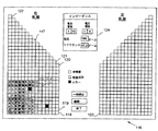
図13Aは、ラップトップPC105の1つの表示スクリーンにおいて、インピーダンスデータの取得を実時間でモニタし、得られた660個のインピーダンス測定値(すなわち、それぞれの乳房について330個の測定値)のどの値でも閲覧し、測定エラーの発生を表示する方法を開示する。右及び左乳房についての330個のインピーダンス測定値のそれぞれは、ここでは正方形で描かれているがこの形態には限定されない、ピクセル117で表される。図13Bの外側正方形119'でさらに示されるように、それぞれの側の下部の15×15個のピクセルはインピーダンス行列を作成するために用いられる225個の測定値である。これには正方形の対角線上の、“×”で埋められ、参照数字117'が付された正方形で示される15個のZ同測定値が含まれる。上部傾斜区画117''は、インピーダンス行列内の15個のZ同値を補完するために必要な、(“×”で埋められている)残りの105個のZ同測定値を表す。初めは、図13Aの全てのピクセルが空白である。まず右乳房について、それぞれの測定値が得られる毎に、右下隅のピクセル118が初めに埋められ、次いで最下段の行が右から左に順次埋められてゆく(この行は電極1と2の間に注入された電流及び電極1と2,1と3,・・・,1と16の間で測定された電圧を表す)。次に、1段上の行のピクセル119が埋められ、次いでプロセスの進行とともにこの行が右から左に順次埋められてゆく(この行は電極1と3の間に注入された電流及び電極1と2,1と3,・・・,1と16の間で測定された電圧を表す)。ピクセル120から始まる、15段目の行(この行は電極1と16の間に注入された電流及び電極1と2,1と3,・・・,1と16の間で測定された電圧を表す)が完全に埋まるまで、プロセスが繰り返される。これらの225個のピクセルは、上述したように、インピーダンス行列を表す。残りの105個のZ同測定値については、同様の態様で、ピクセル121から始まり、右から左に順次ピクセルを埋めていきながら、330番目のピクセル122が埋まるまで、ピクセル埋めが進行する。測定値の実時間エラーチェックは、一貫性及び期待値範囲内への適合のような要因に対して実施され、エラーは、ピクセル埋めプロセス中にエラー随伴ピクセルにおいて動的に表示される。エラーが検出されたピクセル(測定値)を正常に測定されたピクセル(測定値)と区別するために、グレイスケールまたはカラーコードが用いられる。エラーチックを含む全プロセスにかかる時間は30秒より短い。
【0090】
いずれの乳房電極アレイも検査前に貼り付けられるから、左乳房についてのインピーダンス測定及び、その結果としての、ピクセル埋めは右乳房完了後事実上直ちに開始される。ピクセル埋めは、右乳房についてのシーケンスの鏡像関係で進行し、左下隅のピクセル123から開始され、次いで、行に沿って左から右に進む。表示は、相同並行測定の感覚を伝えるため、上記の態様で進行するようになされる。インピーダンススキャンが完了すると、どの測定値も、矢印カーソルを対応するピクセルに重ねてクリックすることにより、ウインドウ124で閲覧することができる。ウインドウ124は、用いられた電流注入電極及び電圧測定電極を表示し、抵抗及びリアクタンスの値を表示する。本発明のエラー検出システムにしたがい、一貫していないか、または(一般に臨床データから決定される)正常なまたは疾患のある組織に対する期待値限界の外にある、測定値に対応するどのピクセルも、色またはグレイスケールにより、本例では黒の塗りつぶしとして、表示される。矢印カーソルをそのようなピクセルに重ねてクリックすれば、問題をおこしたと思われる1つ(または複数の)電極を示す平文メッセージがウインドウに表示されるであろう。
【0091】
データ解析
( A ) 差インピーダンス行列
乳房は、M+1個の(本議論においては、単に“電極”と称され、1つの電極が電極偏倚なしに電流注入にも電圧測定にも用いられ得る)電極対をもつ、非一様導電物体と見なすことができる。電位ゼロの基準電極として、1つの電極が割り当てられる。基準電極における電流は他のM個の電極に印加される電流の総和である。インピーダンス行列Zは、i=1,2,3,...,Mとして、i番電極を通る電流である、電流Iiと、i番電極と基準電極の間の電位差である、電圧Viの間を、下式:
【数5】
で関係付け、この式はV=Z×Iと簡約することができる。
【0093】
上述したようなM+1個の電極をもつ物体に対しては、インピーダンス行列はM×M行列:
【数6】
として定義される。
【0095】
それぞれの行列要素Zij(i,j=1,2,3,...,M)は、j番電極における電流を除く全ての電流がゼロに等しい場合には:
【数7】
に等しい。ある与えられた被験者において、インピーダンス行列は、ある与えられた乳房電極パターンに対して一意的であり、したがってその乳房の“署名”を表す。本発明で構築されるインピーダンス行列を含む、あるタイプの行列には固有値と呼ばれる特性値及び固有ベクトルと呼ばれる特性ベクトルがともなう。これらの行列、本例においては15×15インピーダンス行列のそれぞれは、数学的解析により、それぞれの行列に特有の15個一組の数値すなわち15個の固有値で表され得るという意味において、独特である。さらに、それぞれの固有値には、その固有ベクトルである、一意的な15元ベクトルがともなう。固有値及び固有ベクトルは行列の特性を表わし、インピーダンスは疾患から生じる組織変化に敏感であるから、本発明は、固有値及び固有ベクトルを疾患状態の検出及び診断手段として用いる。これは、Z行列にも、Zが抵抗成分及び容量性リアクタンス成分のそれぞれに分解されれば、R及びXc行列にも、適用できる。この目的のために利用できる固有値及び固有ベクトルの数は、インピーダンス行列の大きさによって変わり、アレイに用いられる電極の数の増加にともなって、多くなるであろう。
【0097】
ここで、診断のために15×15インピーダンス行列を用いる方法が開示される。本方法は、絶対差行列(ADM)及び相対差行列(RDM)を得ることによる右及び左乳房の間の相同行列比較に基づく。ADMを計算するため、平均インピーダンス(あるいはRまたはXc)値が小さい方の行列が、その行列がつくられた側が悪性細胞をより有していそうであるから、識別される。ADMは、平均値が高いインピーダンス方の行列から平均値が低い方のインピーダンス行列を要素毎に差し引くことにより得られる。相対差行列は、2つの行列の間の相対差を要素毎に計算することにより得られる。得られる行列(ADM及びRDM)は、特性を明らかにすることができ、これらの方法を用いる臨床研究により統計的に有意なノルム及び閾値が確立されていると想定すれば、診断のために以下の手法で用いることができる:
(1)ADM及びRDM行列のノルムを計算する(行列要素の大きさをただ1つの数値で特徴づける標準的な数学的方法)ことによる。あらかじめ確立された閾値より大きいノルムは、平均インピーダンス値が低い方の乳房における悪性腫瘍の指標である;
(2)ADM及びRDMの行列式を計算することによる。あらかじめ確立された閾値より大きい行列式は、平均インピーダンス値が低い方の乳房における悪性腫瘍の指標である;
(3)ADM及びRDMにおける全ての要素の総和を得ることによる。あらかじめ確立された閾値より大きい総和は、平均インピーダンス値が低い方の乳房における悪性腫瘍の指標である;
(4)ADM(またはRDM)の列毎の要素の総和を示す2次元プロットによる。値がより高い列は、対応する電極の近傍に腫瘍がある確率がより高いことを示すから、腫瘍の位置に関する情報が本手法により提供されるであろう;
(5)行列の要素の位置の関数として(ADMの場合には)絶対差または(RDMの場合には)相対差の大きさを示す3次元プロットによる。
【0098】
( B ) 代数ビン差の総和
本発明は、先にZ同と称した、特別なインピーダンス値の集合も、疾患状態の検出及び診断の手段として用いることができる。この集合は、16対電極アレイに対して、120個の要素を有する(図13を参照されたい)。正常な被験者についての相同Z同インピーダンス測定値(及びその他の全てのZ測定値)には、右側対左側で解剖学的及び生理学的な小さな差が必ずあるから、何らかの重要ではない差はある。しかし、一方の側がその電気的特性を変化させる疾患の影響を受けている場合に生じる大きな差を、これらの正常な変動が隠蔽することはない。本発明における一解析方法は、ここでは代数ビン差(SABiD)として知られる計量を用いる。SABiDは以下のようにして得られる。240個のZ同インピーダンス測定値(右側及び左側についてそれぞれ120個)の内の最小値及び最大値がその被験者についてのインピーダンス範囲を定めるために用いられ、次いでこの範囲が、ビンと呼ばれる、12の(または別の数の)、等しく、より狭い範囲に細分される。本発明については、ビンに1から12まで番号が付され、240個のインピーダンス値のそれぞれに、それぞれが入る範囲のビン番号が割り当てられる。付番システムは、ビン1に最小インピーダンス値が入り、ビン12に最大インピーダンス値が入るまで割り当てが進行するように、指定される。次いで、120個の相同Z同部位のそれぞれの間で、代数ビン差がとられる。一般に、癌の位置は知られてはいないであろうから、左ビン番号が右ビン番号から差し引かれるという規約が確立される。与えられたSABiDに120個の代数ビン差値が加算される。乳房に癌が存在すれば、癌が存在する側のZ同測定値にいくらかの量のインピーダンス減少が生じるであろう。これは、その側に対応するより小さなビン番号として、したがって、より大きなビン差として、現れるであろう。加算されるビン差が大きいほどSABiD値は大きくなるであろう。あらかじめ確立された閾値より大きなSABiD値は悪性腫瘍の指標である。あらかじめ確立された閾値は一般に、乳疾患のない被験者からのSABiD値範囲を乳疾患と診断された被験者からのSABiD値範囲と比較する臨床データにより決定される。ビン番号によるインピーダンス値表現は、インピーダンス値を規格化し、SABiDの被験者間比較を確実なものとする。減算に対する上述した規約を用いれば、SABiD値は、右乳房にある腫瘍については負になり、左乳房にある腫瘍については正になるであろう。
【0099】
ビン割り当ての別の方法は、右側及び左側のそれぞれに対する120個のZ同インピーダンス値の最小値及び最大値を用いて、インピーダンス範囲及びそれぞれのビン範囲を、右側及び左側のそれぞれに対して別個に、定めることである。本例においては、やはり1から12までの番号がビンに付され、右側及び左側のそれぞれについての120個のインピーダンス値に右側及び左側のそれぞれに関係付けられた適切なビン番号が割り当てられる。次いでSABiDの計算が上と同様にして進められる。
【0100】
( C ) 扇形セクターノードカウント
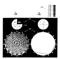
乳房は前平面における円(またはその他の閉じた軌跡)として表すことができ、電極対間のZ同インピーダンスは電極対の位置における円の弦として引くことができる。インピーダンスの大きさは割り当てられたビン番号である。しかし、本明細書に開示される検出方法の基礎は右及び左乳房間の相同比較であるから、好ましいプロットはそれらの差を示すことになろう。したがって、相同弦についてビン番号が比較され、右乳房からの弦のビン番号が左乳房の相同対合のビン番号から差し引かれる。ビン番号が等しければ弦はプロットされない;差があれば、ビン番号が小さい側に弦がプロットされる。ビン差は、適用される[右側−左側]規約にしたがえば、右乳房のプロットについては負になり、左乳房のプロットについては正になるであろう。16対電極アレイに対するビン差弦プロット125が図14に示される。ビン差126は色またはグレイスケールでコード化され、“ビン差1”と表示された最小差は最も薄い灰色で表され、“ビン差9”と表示された最大ビン差は黒の塗りつぶしで示される。図14の構成に用いられたデータは、右乳房の上部内側四分円にある癌により生じている変化を表す。上述したように、次第に濃くなるグレイスケールにしたがうことにより、腫瘍性細胞のより低いインピーダンスで生じたビン差がより大きい領域−この場合は上部内側四分円−に、眼が誘導される。これは基になっている乳房の構造の画像ではなく、それどころか、インピーダンス画像を構成しようとする際の複雑性及び非実際性が意識的に回避されていることを改めて強調しておく。代わりに、多数のインピーダンス測定値が右乳房及び左乳房の精確に相同の部位から得られ、差だけがビン差弦の概念を用いてグラフィック表示される。
【0101】
本発明は、弦プロットにより提供される視覚化の能力を高める乳癌位置の数値指標としての、(参照数字127で示される)扇形セクターノードカウントの使用を開示する。この解析方法は、ビン差コードプロットから出発し、それぞれの電圧/電流電極対を、そこに収束する与えられた数の弦を有するノードと見なす。あるノードにおける総弦収束数カウントは以下の態様で重み付けされる。ビン差が1の収束弦の全てに対してそのノードにカウント1が加えられ、ビン差が2の収束弦の全てに対してそのノードにカウント2が加えられ、ビン差がより大きい弦に対しても同様にカウントが加えられて、そのノードにおける重み付けされた収束カウントとして最終総和が与えられる。図14の例では、円形乳房図が四分円に分割されているが、空間解像度を高めるために扇形セクター数を増やすことができる。16対アレイについては、四分円当たり、境界ノードを含めて、5つのノードがある(境界ノードは2倍のカウントで、すなわち隣接四分円のいずれにも現れる)。含まれる5つのノードについてのノードカウントの和をとることにより、その四分円についての総ノードカウント(例えば、四分円128については−178)が得られる。ノードカウントが最大の四分円、ここでは右乳房の上部内側四分円が、腫瘍の位置を示す。ノードカウントの符号は上述した[右側−左側]規約にしたがう。
【0102】
( D ) ピクセルインピーダンス表示及びピクセル等化
本発明の別の開示は、説明される例では、円周に沿って一様に配された16対の電極から得られる120個のZ同値のようなデータからの前平面における、組織インピーダンス分布を表示するための有効で信頼できる方法を明らかにする。本表示方法は、図15A及び15Bに示されるように、円形領域の17×17ピクセル格子(空間解像度)へのデジタイズに基づく。8ビット(256レベル)のグレイスケールまたは彩色が強度分解能のために用いられる。それぞれの弦に沿う測定されたインピーダンスの分布は等しいとし、様々なピクセルの内部における弦長(弦線分)は相異なり、様々なピクセルを通る弦の数は相異なるであろうことを認めれば、あるピクセルについてインピーダンス強度または値を計算できる。そのようなピクセルの全ての表示がピクセルインピーダンスプロットである。図15Aのピクセルインピーダンスプロット(PIP)129は、全てのZ同値が同じになっている、特別な事例である。PIP129におけるピクセル強度の大きな変動は、様々なピクセルに対する弦の総寄与が一様ではないから、ピクセル等化のための方法が必要であることを示す。上述したように、弦線分はピクセルの境界内部における弦長である。例えば、PIP129の、電極対3と11の間の弦130は13個のピクセルを通過し、その内の始点と終点のピクセルにおいては弦線分が短く、その他の11個のピクセルにおいては弦線分が等しく、より長い。より長い弦線分は、実際は、正方形内でとり得る最大長である、ピクセルの対角線である。単位正方形を仮定すれば、対角線分は2の平方根=1.414である。したがって、弦130が通過する11個のピクセルのそれぞれへの弦130の弦線分寄与は1.414である。その他の弦は、様々な長さで、これらの同じ11個のピクセルを通過し、それぞれのピクセルに弦線分の寄与をして、与えられたピクセルに対する総弦線分を与える。16対電極モデルでは、どのピクセルについても、最大総弦線分は12.44であり、最小総弦線分は0.014である。これらの値は、それぞれの弦について、それぞれのピクセルに対する弦線分寄与を与え、次いでそれぞれのピクセルについて弦線分寄与を総和して総弦線分を与える式から導かれる。デジタル8ビット視覚化に対しては、0から12.44の範囲を0から255に写像するため、20.50(255/12.44)のスケールファクターが用いられる。これにより、最大総弦線分に対する値は12.44から255(12.44×20.50)に変わり、最小総弦線分に対する値は0.014から0.287(0.014×20.50)に変わる。図15Aでは、総弦線分0に黒が割り当てられ、総弦線分255に白が割り当てられた、グレイスケールが用いられている。
【0103】
図15Bは、それぞれのピクセルの値が示されるPIP129の数値版を与える(インピーダンス値が等しいことを想起されたい)。図15Bにおける値には、20.50のスケールファクターが適用されている。境界ピクセル(一部が円内部にあり一部が円の外側にあるピクセル)を考慮に入れなければ、最大総弦線分はPIP129の中央のピクセル131で生じ、全てのZ同値が同じである本例については187に等しい。最小総弦線分は中央ピクセル131に辺を接する4つのピクセル132に生じ、それぞれで、値は53である。最大ピクセル総弦成分値(255)は、一部が円内部にあり一部が円の外側にある、8つの境界ピクセル133に生じる。この理由は、これらの8つの境界ピクセルを通過する弦の数が多く、これらのピクセル内部に入る弦線分が比較的長いことに関係する。境界ピクセル133の10.5%が円の外側にあるという事実を考慮しても、調整された228という値はやはり最大の値である。ピクセルインピーダンスプロットを図15Bのデータで除せば、等化ピクセルインピーダンスプロットが得られる。PIP129の等化により、全てに等しいグレイスケールが与えられたピクセルが得られ、よって真のピクセルインピーダンス値が反映される。
【0104】
本発明は疾患を診断するためにZ同データの並行相同比較を用いるから、(先に用いた規約を守り)[右側−左側]として相同ピクセル値の差をとり、次いで、ピクセル値が小さい方の側にピクセル差をプロットすることにより、ピクセル差インピーダンスプロットを構成できる。このプロットは代数差PIPと称される。未等化代数差PIP135が図16Aに示される。このプロットは右側だけのプロットであり、図14と同じデータ、すなわち右乳房上部内側四分円にある癌を反映するデータを用いて得られた。ピクセル差プロットでは、ピクセル差ゼロに白が割り当てられ、255にスケール変更される最大ピクセル差に黒が割り当てられるように、グレイスケールがコード化される。図16Bは、代数差PIP135のピクセル等化版136を示し、本図では、相同インピーダンス差が区分化され、局限された結果、明解さが向上していることがわかる。
【0105】
相同ピクセル差(代数差)減算の代替として:
【数8】
のような相対相同ピクセル差を、先に述べたように、計算し、等化して、プロットすることができ、このプロットは相対差PIPと称される。
【0107】
ピクセルインピーダンス差の範囲は、代数差PIP及び相対差PIPに対し、別個に導かれるスケールファクターでスケール変更することができる。それぞれのスケールファクターは、スケール変更後の差の最大強度レベルが255になるように、大きな標本母集団で測定された、最大(代数または相対)測定ピクセル差から導かれる。したがって、他のどの被験者のピクセル差も、スケール変更された場合にはより低いレベルになり、よってインピーダンス差の、確実で、一貫した、被験者間比較が可能になる。
【0108】
上述の展開には等化ピクセル差インピーダンスプロットの2次元プロット化が用いられているが、本技術の長所は、立体導体においては電流が本質的に3次元流であるから、3次元インピーダンス差が明らかにされることである。それぞれのピクセルは、ウインドウ面の向こうに延在する組織体積における局限化されたインピーダンス変化へのウインドウのようなものである。
【0109】
( E ) 代数ピクセル差の総和 ( SAPiD )
インピーダンスビン差法によるSABiD及び扇形セクターノードカウントに類似の、代数ピクセル差の総和(SAPiD)及び扇形セクターピクセルカウントの2つの計量を得ることができる。SAPiDは等化された右側PIP及び左側PIPの、ピクセル−対応相同ピクセル毎の相同代数ピクセル差の総和であり、SABiDと同じ機能を果たす。すなわち(一般に臨床データにより決定される)あらかじめ確立された閾値より大きいSAPiD値は悪性腫瘍の指標であり、先に説明した減算規約を用いれば、SAPiD値は、右乳房にある腫瘍については負になり、左乳房にある腫瘍については正になるであろう。SAPiD計量のダイナミックレンジ、したがって蓋然的診断有用性は、SABiDよりもかなり高い。SABiDでは一般に16レベルまでのビンが用いられ、SAPiDについては256レベルが容易に用いられる。
【0110】
( F ) 扇形セクターピクセルカウント
代数差PIPまたは相対差PIPを用い、乳房撮影法に準じて、それぞれの扇形セクター、通常は四分の一円のピクセル値の総和をとることにより、腫瘍の位置の指標が与えられる。本応用の目的のため、これは扇形セクターピクセルカウントと呼ばれる。SAPiDがあらかじめ確立された閾値をこえていれば、扇形セクターピクセルカウントが最大の四分の一円が腫瘍の蓋然的位置を与える。扇形セクターピクセルカウントは等化データを用い、したがって、扇形ノードカウントより正確に腫瘍の位置を特定すると考えることができる。扇形セクターピクセルカウントは、疑わしい領域の拡大像がX線乳房撮影法で撮影される仕方とほとんど同じ仕方で、疑わしい領域に“焦点を合わせる”ため、その扇形セクターとは別の、区分化された円領域で行うことができる。
【0111】
ピクセルインピーダンスプロット、ピクセル等化、ピクセル差インピーダンスプロット、代数または相対ピクセル差の総和及び扇形セクターピクセルカウントの概念を、円周上に一様に配された16対の電極から得られたインピーダンスデータ及び17×17ピクセル格子への円領域のデジタイズを実例として用いて開示した。これらの開示は、より多くの(またはより少ない)電極数から得られるデータ、より高い空間解像度のためのより多数のピクセルの使用、より高い強度分解能のためのより多くのレベル(例えば12ビットまたは16ビット)のピクセルのグレイスケール化または彩色にも、円形、あるいはその他の幾何学的形状に配置することができる非一様配置電極にも、同様に適用される。
【0112】
本発明に対する変形が当業者には容易に明らかであろうことは当然であり、本発明はそのような別形を含むとされる。
【図面の簡単な説明】
【0113】
【図1】4電極インピーダンス測定法を示す図である
【図2】乳房電極アレイの一実施形態を示す図である
【図3】乳房電極アレイ用位置決めテンプレートを示す図である
【図4】図2の乳房電極アレイの改変形態及びリード配線の実装を示す
【図5】本発明の乳房電極アレイの別の実施形態を説明する図である
【図5A】図5の線A−Aに沿ってとられた乳房電極アレイの断面図である
【図6】図5の乳房電極アレイの電気配線を示す
【図7A】図5の乳房電極アレイに電気的に連結するための可撓リボンケーブルを示す図である
【図7B】図7Aの可撓リボンケーブルの電気配線の詳細を示す
【図8】図5の乳房電極アレイを図7Aの可撓リボンケーブルに取り付けるために用いられる3部品ケーブル保持具を示す図である
【図9A−1】図8のケーブル保持具の台座部品の詳細を示す
【図9A−2】図9A−1の線A−Aに沿ってとられた台座部品の断面図である
【図9B−1】図8のケーブル保持具のワッシャ部品の詳細を示す
【図9B−2】図9B−1の線B−Bに沿ってとられたワッシャ部品の断面図である
【図9C−1】図8のケーブル保持具のワッシャ部品の別の実施形態の詳細を示す
【図9C−2】図9C−1の線C−Cに沿ってとられたワッシャ部品の断面図である
【図9D】3部品ケーブル保持具を用いて可撓リボンケーブルに接続された乳房電極アレイの断面図である
【図9E】図7Aの可撓リボンケーブル及び図5の乳房電極アレイに対する図8のケーブル保持具の台座部品及びワッシャ部品の圧縮作用を示す、図9Dで9Eとして表示される領域の拡大断面図である
【図10】別の電気配線を示す、図5の乳房電極アレイの改変形態を示す図である
【図11A】また別の複アーム電極アレイを示す
【図11B】また別の複アーム電極アレイを示す
【図12】本発明に用いられるデータ収集及び解析装置のブロック図である
【図12A】本発明に用いられるデータ収集及び解析装置の試験方法を示す
【図13A】図12の装置の表示スクリーンを示す図である
【図13B】図13Aのインピーダンス表示をさらに詳細に示す
【図14】ビン差弦プロット及びノードカウントを示す図である
【図15A】ピクセルプロットとして示される組織インピーダンス分布を示す図であり、組織インピーダンスは全て等しいとして理想化されている
【図15B】図15Aのプロットのピクセル値の数値表示である
【図16A】図14に用いられたデータと同じデータから得られたピクセルインピーダンス差プロットである
【図16B】図16Aのプロットのピクセル等化版である
【符号の説明】
【0114】
31 乳房電極アレイ
32 アレイアーム
33 電流注入電極
34 電圧測定電極
35 裏当て材
36 中心孔
37 補剛リング
38 アレイアーム連結部
39 位置合せマーク
40 矢印
41 位置合せ孔
42,43,44 導電路
45 コネクタタブ
46 接地導電路【Technical field】
[0001]
The present invention relates to an improved method and apparatus for examining and diagnosing a biological disease state by using a plurality of electrical impedance measurements.
[Background Art]
[0002]
Methods for examining and diagnosing disease states in the body are based on the detection of physical properties or physiological attributes of body tissues and subsequent discrimination between normal and abnormal conditions due to changes in those properties or attributes. . For example, x-ray measures the physical density of tissue, ultrasound measures the acoustic density, and thermal sensing measures the difference in tissue heat. Another measurable tissue property is the electrical impedance, ie, the resistance provided by tissue to the current flowing through it. The electrical impedance values of various body tissues are well known from studies on healthy humans or from resected tissue available after surgical procedures. In addition, the literature fully supports that cancerous changes in tissue result in a decrease in electrical impedance. This finding is consistent across many animal species and tissue types, including, for example, human breast cancer.
[0003]
Heretofore, there have been many reports on detecting breast tumors using electrical impedance imaging, as in
[0004]
However, cancer need not be "seen" to be detected. The presence of cancer can be detected by a marker associated with the cancer, in this case, a change in electrical impedance, and a marker-sensitive technique.
[0005]
One technique for screening and diagnosing disease states in the body using electrical impedance is disclosed in US Pat. According to U.S. Pat. No. 6,037,028, data is obtained in an organized pattern from two anatomically homologous body regions, one of which may be affected. The subset of data thus obtained is processed and analyzed by organizing the data values as elements of an n × n matrix. The characteristics of the matrix can be further determined by the eigenvalues and eigenvectors of the matrix. These matrices and / or eigenvalues and eigenvectors of the matrices can be subjected to a pattern recognition process to check for a match with a known normal or diseased matrix or eigenvalue and eigenvector pattern. Each of the matrices and / or the eigenvalues and eigenvectors of the matrix obtained from each of the homologous body regions is compared to each other using various analytical methods, and then the established criteria for discriminating between normal and diseased states. Can be contrasted.
[Patent Document 1] US Pat. No. 4,486,835
[Patent Document 2] US Pat. No. 6,122,544
DISCLOSURE OF THE INVENTION
[Problems to be solved by the invention]
[0006]
Improve the ability to detect and diagnose disease states by electrical impedance method.
[Means for Solving the Problems]
[0007]
The present invention is directed to an improved method and apparatus for detecting and diagnosing a disease state of a living body by using a plurality of electrical impedance measurements. Although the present invention can be applied to any two homologous body regions, the use discussed is the scrutiny of breast abnormalities, particularly for the presence of benign and malignant tumors. Without intending to be bound by any particular theory, the method of the present invention can be based on the following assumptions and hypotheses:
1. The tumor or tumors will occur in either the right or left breast only, or if they occur in both, they will occur at different homologous locations;
2. The right and left breasts are structurally equivalent and can therefore be considered to be nearly mirror images (homologous) with respect to their impedance characteristics;
3. If the impedance measurement (referred to in this application as an impedance scan) is made in multiple directions or paths through the breast, the presence of a tumor known to have a significantly lower impedance than normal tissue before turning into a tumor is known. Will distort or change the impedance in at least some of the current paths;
4. The reduction in impedance for malignant tumors is greater than for benign tumors, providing a method for discriminating malignant from benign tumors;
5. There will necessarily be some impedance differences between the right and left breasts in a normal individual, but such differences will be smaller than when cancer is present.
[0008]
The method of the present invention is performed by a data collection and analysis device developed for the specific requirements of the present invention. There is also provided an improved breast electrode array of a design and configuration that allows for excellent conformability of the array to the breast surface and precise positioning of the electrodes. This ensures that the number of locations where impedance measurements are obtained from the first body part correspond as accurately as possible to the number of other, homologous locations where impedance measurements are obtained from the second body part. Guaranteed. The device has a number of innovations that provide fast and accurate impedance measurements from numerous electrode combinations and virtually instantaneous data analysis and display. The impedance data is obtained in an organized pattern from two anatomically homologous body regions, one of which may be affected.
[0009]
In one embodiment of the present invention, the electrodes are chosen such that the resulting impedance data can be considered to represent elements of an n × n impedance matrix. The difference between the two matrices is then calculated to obtain a diagnostic metric from each. In one, for each element, the absolute difference between the homologous right and left breast matrices is calculated. In the second, the same procedure is repeated, except that the relative matrix element difference is calculated.
[0010]
In another embodiment of the present invention, a variety of means that allow the calculation of a metric can be used as an indicator of the presence of the disease, or to localize the disease to a particular breast quadrant or sector, to allow for the calculation of metrics. The differences between the corresponding impedance readings at the two body parts are compared. The impedance difference is represented in the present disclosure by a circular pixel plot representing the anterior breast surface, but plots of other shapes on the same or different surfaces can also be effectively made by appropriate selection of electrode geometry and placement. I could make it. In general, under normal circumstances, the current paths can be considered to be substantially the same in two homologous body parts, so the use of impedance differences can result in a large amount of congestion occurring in irregular, three-dimensional current paths. Is erased. The remaining differences are attributed to the disease state and are much easier to handle for analysis.
[0011]
While the example of the invention described is a new and improved method and apparatus for detecting and locating breast cancer, the present invention provides a method for detecting differences in electrical impedance that can be discriminated as a result of a disease or condition. And other diseases or conditions. The present invention is directed to any body region where the electrical impedance of a region with a disease or condition can be compared to an essentially equivalent normal body region, such as in the right and left forearms, right and left thighs or right and left fibula. It can also be used to detect and locate a disease or condition. Further, the present invention provides a method for comparing the electrical impedance of a region with a disease or condition with another normal body region that is not completely equivalent, but has differences that do not change consistently. It can be used to detect and locate a disease or condition in a region, for example, the right and left abdomen. In other words, the difference between the two regions being compared is known and constant in healthy individuals and can therefore be eliminated when making the comparison.
[0012]
In particular, the present invention provides an electrode array for diagnosing the presence of a disease state in a living body, wherein the electrode array is provided on a flexible body, a plurality of flexible arms extending from the flexible body, and a plurality of flexible arms. And a plurality of electrodes arranged on the arm so that an electrical impedance measurement between the electrodes can be obtained. In a preferred embodiment, a plurality of flexible arms are spaced around the flexible body and provided with an electrode pair.
[0013]
Further, the flexible body of the electrode array can include a stiffening member adapted to the leveled portion of the tissue of the living body being diagnosed. In a preferred embodiment of the invention, the stiffening member is in the form of a ring and is provided with an adhesive for fixation to the skin.
[0014]
Further, an adhesive for fixing to the skin can be attached to each of the electrodes of the electrode array. In a preferred embodiment, the adhesive is a hydrogel. In another embodiment, the adhesive is a gel foam pad, particularly a gel foam pad in the form of a hydrogel-filled well.
[0015]
The electrode array may also include means extending at least to some extent between the electrodes to electrically separate the electrodes from each other, at least to some extent. In a preferred embodiment, the means includes a ground conductive path. Further, the plurality of electrodes can include an electrode pair, each electrode pair having a current electrode and a voltage electrode. In this embodiment, the ground conductive path extends at least to some extent between the current electrode and the voltage electrode. Further, each electrode is connected to a companion terminal by a conductive path, and a ground conductive path extends between the conductive path and the companion terminal of each electrode, at least to some extent, to at least partially electrically isolate the conductive path and the terminal from each other. Can be present.
[0016]
A method for forming an electrode array from a plurality of electrode array elements is also disclosed. Each electrode array element has a body having at least one arm, the arm extending from the body, and at least one electrode provided on the arm. The method is:
a) forming a plurality of electrode array element bodies in each of the plurality of electrode array element bodies such that respective arms of the plurality of electrode array elements extend from the main body in spaced relation to each other to form a main body of the electrode array; Stacking electrode array elements; and
b) clamping the plurality of electrode array elements together;
including.
[0017]
Alignment means may be provided to ensure that the arms of each electrode array element are spaced apart from each other and extend around the main body of the electrode array. Further, a holding member is used to clamp the plurality of electrode array elements together, and the holding member may include a stiffening member.
[0018]
The present invention also provides a method of confirming whether an electrode array for use in diagnosing a part of a living body is properly connected to an electronic module. The electrode array includes a conductive path and a connector for connecting the conductive path to the electronic module. The method includes attaching a conductive path to a terminal of the connector, connecting the electrode array to the electronic module using the connector, and testing whether the conductive path is properly connected to the terminal of the connector. . In the disclosed embodiment, the conductive path is a ground loop.
[0019]
The present invention also provides a template for positioning an electrode array on a portion of a living body to be diagnosed for the presence of a disease state. The template includes a body having a plurality of spaced parallel lines and at least two alignment marks disposed on the plurality of spaced parallel lines. The body can be made of a flexible and transparent material. Further, the body can be elongated in a direction perpendicular to the parallel lines and can have at least one line extending in a direction perpendicular to the parallel lines. Preferably, the template has at least two alignment marks arranged on a line extending in a direction perpendicular to the parallel lines. The body of the template may provide an opening through which at least a portion of the body part to be diagnosed is visible. The alignment marks can be spaced around the opening.
[0020]
Also disclosed is a method of positioning an electrode array over a site in a living body using a template. The method is:
a) marking the organism with a line on or near the site to be diagnosed;
b) placing a positioning template on the site to be diagnosed and aligning at least one of the spaced parallel lines with a line provided on the living body;
c) marking on the living body at the position of the alignment mark of the template; and
d) positioning the electrode array on the site to be diagnosed by aligning the corresponding alignment mark of the electrode array with a mark on the living body by the template;
including.
[0021]
The present invention also discloses a connection member for connecting the electrode array to a connector that electrically connects the electrode array to the electronic module. The connection member includes a holding member for receiving the electrode array and the connector and keeping them in electrical contact with each other, and a clamp for clamping the electrode array and the connector together to provide an electrical connection between the electrode array and the connector. It is provided with a clamp member for ensuring contact. The clamp member includes a compression member for applying a compression force to the electrode array and the connector. The retaining member comprises a pedestal and a protrusion extending from the pedestal, into which a portion of the electrode array and a connector can be fitted. The clamp member may further include a washer that fits into the protrusion of the holding member and fits into the electrode array and the connector. The pedestal of the holding member may include at least one ridge protruding from the pedestal for mating with the electrode array and the connector on the side opposite the washer. In a preferred embodiment, the projection is a threaded tube and the compression member is a clamping nut. In addition, the pedestal may further include alignment pins to ensure that the electrode array and the connector are in correct electrical contact with each other.
[0022]
The washer may comprise at least one groove, the groove being adapted such that each of the concentric ridges projecting from the pedestal fits into the groove. In one disclosed embodiment, the washer is provided with at least two grooves, each groove being adapted such that at least one of the ridges projecting from the pedestal fits into the groove. In another embodiment, the washer is provided with at least two spaced concentric ridges, between which each of the concentric ridges projecting from the pedestal fit.
[0023]
A method of connecting an electrode array to a connector that electrically connects the electrode array to an electronic module is also disclosed. The method is:
a) keeping the electrode array and the connector in electrical contact with each other; and
b) clamping the electrode array and the connector together to ensure electrical contact between the electrode array and the connector;
including.
[0024]
Further, a method for minimizing the number of connections in the conductive paths and connectors of the electrode array is disclosed. The method is:
a) providing a plurality of spaced unconnected conductive surfaces on the electrode array;
b) providing a plurality of spaced unconnected conductive surfaces on the connector, wherein two of the conductive surfaces are selected to be connected to a conductive path; and
c) by overlapping an uncoupled conductive surface spaced from the electrode array with a spaced unconnected conductive surface of the connector to form a continuous conductive path between two selected conductive surfaces. Leaving the array and the connector in electrical contact with each other;
including.
[0025]
In a preferred embodiment, the spaced unconnected conductive surfaces on the electrode array are spaced about the aperture provided by the array, and the spaced unconnected conductive surfaces on the connector are Are spaced around similar openings provided by The two selected conductive surfaces of the connector are adjacent and a gap is provided between the unconnected conductive surfaces of the electrode array such that a gap is disposed for the adjacent selected conductive surface of the connector. When the electrode array and the connector are placed in a superimposed relationship, there is no continuous path directly connecting selected adjacent conductive surfaces of the connector. In a preferred embodiment, alignment means are provided to ensure that the electrode array and the connector overlap to form a continuous conductive path between the two selected conductive surfaces. Further, in the disclosed embodiment, the conductive path is a ground conductive path.
[0026]
Further, a method is disclosed for verifying effective electrical contact between a plurality of spaced unconnected conductive surfaces of an electrode array and a plurality of spaced unconnected conductive surfaces of a connector. The method is:
a) the electrode by overlapping an unconnected conductive surface spaced in the electrode array with a spaced unconnected conductive surface of the connector so as to form a continuous conductive path between two selected conductive surfaces; Leaving the array and connector in electrical contact with each other; and
b) measuring a test signal on a conductive path between the two selected conductive surfaces to see if a valid electrical contact has been established;
including.
[0027]
In the disclosed embodiment, the conductive path is a ground conductive path, and the electrical resistance is measured and compared to a predetermined value for valid electrical contact. Further, the step of keeping the electrode array and the connector in electrical contact with each other includes leaving each terminal for an electrode of the electrode array in electrical contact with a respective conductive surface of the connector. The test determines whether proper electrical contact between each terminal and the conductive surface has been established.
[0028]
Further, the present invention discloses an apparatus for obtaining and processing impedance measurements from an electrode array, the apparatus comprising means for connecting the apparatus to the electrode array (e.g., a multiplexer), for generating an impedance measurement sequence. Means for controlling the connection means (e.g., a multiplexer controller), computer means for controlling the sequence control means and means connected to the computer means for displaying the impedance measurements and any analysis results thereof. Prepare. In a preferred embodiment, the apparatus further comprises at least one EEPROM chip containing a selection pattern for generating an impedance measurement sequence and a counter for sequencing the multiplexer through a series of impedance measurements. The display means may comprise a display screen for providing visual confirmation of the impedance measurement and its analysis or a printer for hard copy of the impedance measurement and its analysis.
[0029]
In the disclosed embodiment, each of the impedance measurements is displayed as a grid element. Means are provided for identifying a corresponding electrode of the electrode array used to obtain the impedance measurement represented by a given grid element. Further, identification means can be used to provide an impedance measurement represented by a grid element. In addition, means for indicating that the measured impedance value represented by the grid element does not correspond to a predetermined expected value can be provided to the display means.
[0030]
Also disclosed is a multiplexer test method of the present invention that uses two substantially equivalent multiplexers. The method reverses one of the multiplexers. The method is:
a) connecting each of the outputs of the two multiplexers to each other;
b) applying a calibration load to the input of the inverse operation multiplexer;
c) controlling the operation of the two multiplexers simultaneously with an equivalent output selection sequence; and
d) measuring the calibration load through the input of the positive working multiplexer;
including.
[0031]
Specifically, the measurement of the calibration load is an impedance measurement.
[0032]
The present invention also provides a number of methods for diagnosing a potential disease state in one of substantially similar first and second sites of a living organism. One way is:
a) obtaining a plurality of impedance values over a predetermined portion of each site to produce a first set and a second set of impedance measurements, wherein the first set comprises a first set of And the second set is for the second portion, and corresponds to each of the first set of measurements when the impedance measurements are taken over the corresponding portion of each portion. The measurement is in a second set;
b) identifying the set with the lower average impedance value;
c) creating an absolute difference set by subtracting each measurement of the set having the lower average impedance value from the corresponding measurement of the other set; and
d) analyzing the absolute difference set to diagnose a possible disease state;
including.
[0033]
In a disclosed embodiment, each of the first and second sets is arranged in a respective mathematical matrix, and the absolute difference set is an absolute difference matrix. The absolute difference matrix can be used to calculate a matrix norm that is compared to a pre-established threshold to diagnose a possible disease state. The absolute difference matrix can also be used to calculate a determinant that is compared to a pre-established threshold to diagnose a possible disease state. In addition, the sum of all the elements of the absolute difference matrix can be calculated and compared to a pre-established threshold to diagnose a possible disease state.
[0034]
A visual indication for diagnosing the likelihood of the disease state and its location is obtained by summing the values of each column of the absolute difference matrix, and then summing them up in a graph, for example the height of a bar in a two-dimensional graph. By expressing as, it can also be provided. By plotting the value of each element of the absolute difference matrix as a function of the position of the value in the matrix, another visual indication for diagnosing the likelihood of a disease state and its location can be obtained. Such a plot can be a three-dimensional graph.
[0035]
Another method of diagnosing a potential disease state in one of the first and second substantially similar sites of the organism is:
a) obtaining a plurality of impedance measurements over a predetermined portion of each site to create a first set and a second set of impedance measurements, the first set comprising a first set of impedance measurements; A set for the sites, the second set is for the second site, and when the impedance measurements are taken over the corresponding portion of each site, each set of measurements in the first set Having a corresponding measurement in the second set;
b) creating a relative difference set by calculating a relative difference between each measurement from the first set and the corresponding measurement in the second set; and
c) analyzing the relative difference set to diagnose a possible disease state;
including.
[0036]
Again, each of the first and second sets can be arranged in a respective mathematical matrix, and the relative difference set is a relative difference matrix. The relative difference matrix can be used in a manner similar to the absolute difference matrix to diagnose the likelihood of a disease state.
[0037]
Another way is:
a) obtaining a plurality of impedance measurements over a predetermined portion of each site to create a first set and a second set of impedance measurements, wherein the first set comprises a first set of impedance measurements; A set for the sites, the second set is for the second site, and when the impedance measurements are taken over the corresponding portion of each site, each set of measurements in the first set Having a corresponding measurement in the second set;
b) calculating the impedance range by subtracting the minimum impedance measurement from the first and second sets from the maximum impedance measurement of each set;
c) creating a plurality of numbered bins by subdividing the impedance range into a plurality of smaller ranges, and then sequentially numbering the plurality of smaller ranges;
d) assigning a bin number to each of the impedance values from the first and second sets;
e) creating a bin difference set by subtracting the bin number of each impedance measurement from one of the first and second sets from the bin number of the corresponding respective impedance measurement in the other set. ;as well as
f) analyzing the bin difference set to diagnose a possible disease state;
including.
[0038]
In the method, the sum of all bin difference values of the bin difference set is calculated and compared to a predetermined threshold for diagnosing a possible disease state.
[0039]
A similar method is:
a) obtaining a plurality of impedance measurements over a predetermined portion of each site to create a first set and a second set of impedance measurements, the first set comprising a first set of impedance measurements; A set for the sites, the second set is for the second site, and when the impedance measurements are taken over the corresponding portion of each site, each set of measurements in the first set Having a corresponding measurement in the second set;
b) calculating a first impedance range for the first set by subtracting the minimum impedance measurement from the first set of maximum impedance measurements; and a minimum impedance measurement from the second set of maximum impedance measurements. Calculating a second impedance range for the second set by subtracting
c) creating a plurality of first numbered bins by subdividing the first impedance range into a plurality of first narrower ranges, and sequentially numbering the plurality of first narrower ranges; and Creating a plurality of second numbered bins by subdividing the impedance range of the plurality of second smaller ranges into a plurality of second smaller ranges, and then sequentially numbering the plurality of second smaller ranges.
d) assigning one of the first bin numbers to each of the impedance measurements from the first set and assigning one of the second bin numbers to each of the impedance measurements from the second set;
e) creating a bin difference set by subtracting each bin number of the impedance measurement from one of the first and second sets from each bin number of the corresponding impedance measurement from the other set; as well as
f) analyzing the bin difference set to diagnose a possible disease state;
including.
[0040]
In a disclosed embodiment, the sum of all bin difference values of the bin difference set is calculated and compared to a predetermined threshold for diagnosing a possible disease state.
[0041]
Another method of diagnosing a potential disease state in one of the first and second substantially similar sites of the organism is:
a) obtaining a plurality of impedance measurements taken between predetermined points surrounding each site to create a first set of impedance measurements and a second set of impedance measurements; The first set is for the first part and the second set is for the second part, the first set when the impedance measurements are taken between corresponding points. The measurements corresponding to each of the measurements of the set of the second set are in the second set;
b) assigning a bin number to each of the impedance measurements from the first and second sets;
c) each point by graphically displaying a plurality of points as nodes on a path surrounding the part for each part and impedance measurements taken between the plurality of points as chords extending between the nodes; Creating a bin string diagram for
d) dividing each of the graphical representations surrounding each part into sector sectors; and
e) analyzing bin strings that converge on a given node in the sector sector to diagnose a possible disease state;
including.
[0042]
In the disclosed embodiment, each sector sector graphically displays the total number of bin strings that converge on all of the nodes contained within each sector. Further, in a preferred embodiment, the difference between the corresponding bin chords for each location is plotted as the bin chord on the graphical display for the location having the smaller bin number. The calculated value of the number of bin chords that converge on a given node is then weighted depending on the difference between the bin numbers from the first set and the corresponding bin numbers from the second set.
[0043]
Another method of diagnosing a potential disease state in one of a first and second substantially similar site of a living body is:
a) obtaining a plurality of impedance measurements taken between predetermined points surrounding each site to create a first set of impedance measurements and a second set of impedance measurements; The first set is for the first part and the second set is for the second part, the first set when the impedance measurements are taken between corresponding points. The measurements corresponding to each of the measurements of the set of the second set are in the second set;
b) creating a pixel grid from a chord plot created by impedance values taken between a plurality of points; and
c) analyzing the pixel grid to diagnose a possible disease state;
including.
[0044]
For this method, the pixel intensity in the pixel grid is determined from the chord passing through the pixel, i.e., the number of chords passing through the pixel, the length of the chord segment passing through the pixel, and the chord passing through the pixel It is determined by the impedance value. Pixel intensity can be equalized to compensate for differences in the number of strings that can pass through various pixels and the length of chord segments that pass through pixels. Once equalized, the pixel intensity indicates only the impedance value.
[0045]
Further, a pixel difference set can be created by subtracting pixel impedance values from one of the first and second sets from impedance values of corresponding respective pixels of the other set. In the method, the sum of all the difference values of the pixel difference set is calculated and compared to a predetermined threshold for diagnosing a possible disease state.
[0046]
The pixel intensity is displayed visually, and the visual display can be computer generated to display a plurality of levels representing various impedance values. In a preferred embodiment, the computer-generated visual display has 256 intensity levels to represent various impedance values.
[0047]
The pixel grid may be a pixel algebraic difference plot derived by taking the difference between corresponding impedance pixel measurements taken between a plurality of points in the first and second portions. Further, the pixel grid can be a pixel relative difference plot derived by calculating a relative difference between corresponding impedance pixels from a plurality of points of the first and second portions.
[0048]
Further, rescaling the range of pixel impedance intensities for a pixel algebraic difference plot or for a pixel relative difference plot using a scale factor derived for the algebraic difference plot and for the relative difference plot. The scale factor for each type of plot is predetermined so that the maximum pixel intensity level is 256 when applied to a subject who has seen the maximum pixel difference.
[0049]
Furthermore, for both pixel algebraic difference plots and pixel relative difference plots, the pixel grid is divided into multiple sector sectors, and for each of the multiple sector sectors, all pixels in each sector Is graphically displayed.
BEST MODE FOR CARRYING OUT THE INVENTION
[0050]
For a better understanding of the present invention and to show more clearly how the present invention may be implemented, reference is made, by way of example, to the accompanying drawings, which show preferred embodiments of the present invention.
[0051]
Electrical impedance and 4-electrode measurement method
The electrical impedance is measured using four electrodes as shown in FIG. The
(Equation 1)
It is. By using independent electrode pairs for current injection and voltage measurement, the biasing effect on the voltage measurement electrodes is minimized and more accurate impedance measurements can be obtained.
[0053]
Impedance consists of two components: resistance and capacitive reactance (or equivalently, the magnitude and phase angle of the impedance). In the present invention, any component is measured, displayed, and analyzed. However, for purposes of describing the present invention, only the resistance component will be used and interchangeably referred to as resistance or the more universal term impedance.
[0054]
Breast electrode array
FIG. 2 discloses a
[0055]
[0056]
The backing material of the
[0057]
An alignment mark made on the skin using a
[0058]
FIG. 4 discloses a breast electrode array 19 that is a modification of the
[0059]
The breast electrode array 19 includes special conductive paths terminating at connectors 25 and 26 to form an electrical ground loop 24. The ground loop 24 improves the isolation of the current injection electrode 28 from the voltage measurement electrode 29. In addition, ground loop 24 allows electrical testing to verify that the right and left arrays are attached to the correct side. One of the rims of ground loop 24 connects to the terminals of connector 25 on the array intended for the right breast, and on the array intended for the left breast, the same rim is removed from connector 25 and the unused connector is used. 27 is connected to one terminal. Testing for the expected right or left continuity of ground loop 24 identifies the right and left arrays.
[0060]
The tail 23 of the array can be longer or shorter, angled or straight, can have various shapes (eg, hourglass), reduce the spacing of the conductive paths 20 or reduce The width can be reduced by printing the conductive path 20 on both sides corresponding to the use of the electrical connector. An alignment mark 30 is used, similar to the alignment mark 10 of the
[0061]
5 and 5A disclose another preferred breast electrode array 31 of the present invention. Sixteen
[0062]
As shown in FIG. 5A, the current injection electrode 33 and the
[0063]
FIG. 6 shows an example of the electrical wiring of the breast electrode array 31. The conductive paths 42, 43 and 44 are printed on the side of the backing material 35 not facing the subject's skin (back side). The conductive paths 42 and 43 extend through the through holes (not shown) to the side of the backing material 35 facing the subject's skin (abdominal side), and connect the base layers of the current injection electrode 33 and the
[0064]
Conductive paths 42 and 43 connect to connector tab 45 at the other end. There are also 16 ground conductive paths 44, one of each of the ground conductive paths 44 being disposed between the current injection electrode 33 and the
[0065]
FIG. 7A discloses a flexible flat ribbon cable pair 48 consisting of individual ribbons 49 and 50, each of which ends at one end with a connector tab 51 and 52 of a circular connector ring 53. There are 34 conductive paths, not shown in the figure. These rings have a center hole 54, the diameter of which is substantially the same as the diameter of center hole 36 of breast electrode array 31. The conductive paths of the ribbons 49 and 50 terminate at the other end in individual rows of a standard two row 72 pin connector 55, which is subsequently connected to the mating connector of the front end electronic module of the present invention, described below. It is attached. As is standard in the manufacture of flexible circuits, ribbons 49 and 50 are polyimide material, copper is used for the conductive paths, and connector tabs 51 and 52 are tin / lead plated copper. . Each of the ribbons 49 and 50 has thirty-four conductive paths printed in a standard double-sided manner. Sixteen of the conductive paths are for current injection electrodes, 16 are for voltage measuring electrodes, and two conductive paths are connected to electrical ground, but generally use more ground connections I could do that. Both surfaces of the ribbons 49 and 50 are insulated with a thin layer of polyimide, except for the inner non-insulated portion of the connector ring 53 which is defined by the outer edge 57 of the connector tab 51.
[0066]
FIG. 7B shows the details of the electrical wiring of the connector ring 53 and the adjacent portion of the ribbon 49 or 50. Double-sided printing of the conductive path is indicated by a solid line 58 on one side and a dashed line 59 on the other side. Each one of the conductive paths terminates in a respective connector tab 51. However, only two connections 60 are made to ground connector tabs 52 in the conductive path, and the remaining 14 ground connector tabs will be connected in the manner described in the following sections. As shown, the ribbons 49 and 50 can also be provided with alignment holes 61 for receiving alignment pins of the cable retainer as described below. Although two alignment holes 61 are shown in FIG. 7B, more alignment holes could be used. The location of such alignment holes could be different between ribbons 49 and 50 to provide a way to detect and / or prevent flipping the electrode array or swapping the right and left of the electrode array.
[0067]
A connector member for attaching the breast electrode array 31 to each of the flexible ribbons 49 and 50 is disclosed. The connector member receives the electrode array and the flexible ribbon and holds them in electrical contact with each other. And a clamp member for surely maintaining the electrical contact between them. In the embodiment shown in FIG. 8, the connector member is a cable holder 62. The cable holder 62 has three components: a pedestal part 63, a washer 64, and a tightening nut 65. These components are made from materials such as, for example, DuPont's Delrin® acetyl copolymer for strength, stiffness, hardness, dimensional stability and non-conductive properties. Other materials with similar combinations of properties could be used. The pedestal component 63 comprises a flat annular flange 66 and a central, hollow, threaded cylindrical tube 67. The ring flange 66 has two concentric ridges 68 and two alignment pins 69 on the surface. These pins can be made from a material such as Delrin or a metal such as stainless steel. Further details of the pedestal part 63 are shown in FIGS. 9A-1 and 9A-2, where the same reference numbers as in FIG. 8 apply. As specifically shown in FIG. 9A-2, the ridges 68 are tapered to facilitate alignment with the preferably tapered, mating grooves, such as the grooves 70 of the washers 64 shown in FIG. 9B-2. It has an attached side.
[0068]
The washer 64 has two circumferential grooves 70 and two alignment holes 71 as shown in FIGS. 9B-1 and 9B-2. Another embodiment of the washer 64 is the washer 72 shown in FIGS. 9C-1 and 9C-2. In this embodiment, the washer 72 has two circumferential ridges 73 and 74 and two alignment holes 75 that form a groove-like structure in the main body of the washer 72. As shown in FIG. 9C-2, the outer peripheral ridge 73 is higher than the inner peripheral ridge 74.
[0069]
The third component of the cable holder 62 of FIG. The tightening nut 65 has a notched knob 76, a flange 77 and an internal thread groove 78.
[0070]
FIG. 9D shows the assembled breast electrode array 31, flexible ribbon cable 48 and cable retainer 62, along with pedestal component 63, washer 72 and tightening nut 65.
[0071]
In the assembly operation, the breast electrode array 31 is connected to the flexible ribbon cable pair 48 as follows. The threaded cylindrical tube 67 of the pedestal part 63 of the cable holder 62 is inserted into the center hole 36 of the breast electrode array 31 from the ventral side of the array 31 on the side where the stiffening ring 37 is attached, and the pedestal part 63 alignment pins 69 are inserted through alignment holes 41 of breast electrode array 31. To ensure the contact of the stiffening ring 37 with the breast skin, the diameter of the ring flange 66 of the pedestal part 63 is slightly smaller than the inner diameter of the stiffening ring 37, and the thickness of the ring flange 66 is greater than the thickness of the stiffening ring. thin. At this point, the protective adhesive sheet of the stiffening ring 37 can be peeled off, and the breast electrode array 31 having the pedestal part 63 therein is disposed around the nipple. After the breast electrode array 31 is turned and positioned in the correct position, the stiffening ring 37 is pressed into firm contact with the skin. This points the pointing arrow 40 (see FIG. 5) of the alignment mark 39 upwards to point to the head, and then moves all of the alignment marks 39, such as the
[0072]
Then, the following conditions: (1) the exposed electrode tabs 51 and 52 of the connector ring 53 face the electrode tabs 45 and 46 of the breast electrode array 31; (2) the alignment holes 61 of the connector ring 53 And (3) the flexible ribbon cable 48 is oriented so that the 72-pin connector 55 faces the subject's head. The ring 53 is slidingly fitted on the cylindrical tube 67 of the pedestal part 63. By satisfying the above conditions, the electrode tab 51 of the connector ring 53 is completely overlapped with the electrode tab 45 of the breast electrode array 31, and the trapezoidal electrode tab 52 of the connector ring 53 is replaced with the trapezoidal electrode tab of the breast electrode array 31. Slight overlap with 46 would form a staggered continuous electrical path. This aspect of the invention has two features. First, only two ground conductive paths are needed because the electrode tabs 46 and 52 form a continuous electrical path between the two ground connections 60 shown in FIG. 7B. Second, any attachment other than a correct attachment will cause an interruption (open circuit) in the continuous electrical path, and furthermore, that the electrode tabs 51 of the connector ring 53 will be properly aligned with the electrode tabs 45 of the breast electrode array 31. An electrical test of the proper attachment of the connector ring 53 to the breast electrode array 31 is provided, as will also be shown. The selection of the size, shape, and degree of overlap of the bonding electrode tabs 46 and 52 establishes the desired magnitude of rotational misalignment sensitivity and allows the measurement of the resistance of the conductive path provided by these electrode tabs. It could also be used to get an indication of the degree of misalignment and contact pressure. By changing the number and pattern of lost connections of the ground electrode tabs, and then relying on establishing a ground connection circuit that requires correct staggered rotational alignment of the connector ring 53 and the ground electrode tabs on the breast electrode array 31 Other embodiments of the above approach are possible.
[0073]
Following attachment of the connector ring 63 to the cylindrical tube 67 of the pedestal part 63, the washer 72 and then the tightening nut 65 are attached to the cylindrical tube 72. The washer 72 is turned so that the positioning hole 71 of the washer 72 fits into the positioning pin 69 of the pedestal part 63, thereby preventing the washer 72 from rotating after the fitting. Further, the washer 72 (or washer 64), alone or in combination with the flexible ribbon cable 48 and the breast electrode array 31, may be at least as high as the alignment pins 69, as shown in FIGS. 9D and 9E. It is becoming. The washer 72 can then be turned into tight contact with the connector ring 53 by turning the tightening nut 65. Thus, the electrode tabs 51 and 52 of the connector ring 53 are brought into contact with the electrode tabs 45 and 46 of the breast electrode array 31. This contact is made between the ridge 68 of the pedestal part 63 and the complementary ridges 73 and 74 of the washer 72, respectively, for the flexible polyimide material of the connector ring 53 and the flexible polyester of the breast electrode array 31, or It is ensured by the effect of the compressive force when clamped between the 64 complementary grooves 70. The compressive force bends the flexible material, and the ridges 68 of the pedestal part 63 cause the flexible material to act in the manner of a coned disc spring, which is the fulcrum of a circular bent beam, as shown in FIG. 9E. This action also produces the desired rubbing contact action of the electrode tabs as the flexible material assumes a shallow dish shape under compression. The contact surface of the washer and the tightening nut of the cable retainer 62 may be such that the projections on one surface coincide with the holes on the other surface to provide tactile and audible guidance of the degree of compression, or The structure can be made such that the protrusions on both surfaces are staggered. By fitting the projections into the holes or butting the surface projections, loosening of the clamping nut could be more reliably prevented.
[0074]
When the breast electrode array 31 is connected to the flexible ribbon cable 48 in the correct orientation and attached to the breast by the adhesive on the stiffening ring 37, all of the attachments of the
[0075]
FIG. 10 discloses a breast electrode array 79, which is a modification of the breast electrode array 31 showing alternative electrical wiring. In this variation, one of the array arms is widened and extended to form a connecting tail 80 similar to the breast electrode array 19 of FIG. The positions of the current injection electrodes 81 and the voltage measurement electrodes 82 have not been changed in this example to keep the geometric pattern of all electrodes the same as the breast electrode array 31. By increasing the width of the array arm, the conductive paths 83 and 84 from the remaining 15 pairs of current injection electrodes 85 and voltage measuring electrodes 86, respectively, along with the conductive paths for electrodes 81 and 82, are routed at connection tail 80. It is possible to take. The double-sided printed conductive path is shown by a solid line on one side and a dashed line on the other side. All of the conductive paths terminate in connectors 86, and generally all of the features provided in the tail 23 of FIG. 4, such as the use of a ground connector 87 to verify the correct right and left placement of the breast electrode array, are in this example. Can be equally applied. Although not shown, the use of grounded conductive paths for improved isolation between the current injection circuit side and the voltage measurement circuit side could be implemented as intervening conductive paths and / or conductive ink areas.
[0076]
11A and 11B disclose another method of implementing a multi-arm electrode array. In particular, FIG. 11A discloses a basic four-arm electrode array 88. The basic four-arm electrode array 88 has conventional, tacky hydrogel current injection electrodes 89 and voltage measurement electrodes 90 on a thin, transparent polyester film. Each arm 91 of the array has an alignment mark 92 and an alignment hole 93. There is a central hole 94 in which the nipple is centered during use. The electrode wiring is not shown for simplicity. Other basic configurations, with fewer or more arms, arms of different lengths combined, and arms rotated equally or unequally with respect to each other, also create electrode arrays of various sizes and shapes. Could be used for In addition, three or more electrodes could be placed on each arm 91 to measure impedance radially or in another geometry.
[0077]
FIG. 11B shows a plan view on the electrode side of a 16-arm electrode array 95 in which four 4-arm electrode arrays 88 are assembled. The electrode array 88 has a threaded hollow cylinder 97 (only the bottom can be seen) of the array holder 96 fitted into the hole 94, and the electrode array 88 is further rotated to allow only the bottom of the array holder 96 to be seen. ) Alignment pins 96 are positioned at predetermined positions by fitting into alignment holes 93 of electrode array 88, and then joined by threading a hollow cylinder 97 through a washer and nut. . The bottom of the array retainer 96 is similar to the stiffening ring 37 in that the bottom surface is generally flat and rigid and has an adhesive coating to provide initial application of the assemblage to the skin. For the reasons mentioned for the stiffening ring 37 of the breast electrode array 31, the array holder 96 forces the skin surface to which the array holder 96 is applied to be flat. The correct position of the electrode array 95 on the breast is obtained by overlaying the alignment marks 92 of the electrode array 95 on the ink marks made on the skin by the positioning template, as described above.
[0078]
Generally, the electrodes in the various disclosures herein are depicted as rectangular, and the electrode pairs are arranged in parallel. Many other configurations with electrodes of various shapes, including but not limited to circular, oval, annular and C-shaped, could be used to advantage. The current injection electrode and the voltage measurement electrode do not need to have the same shape, need to have the same dimensions, and do not need to be parallel. For example, a C-shaped voltage measuring electrode and a small circular current injection electrode disposed between the open ends of the C-shaped voltage measuring electrode can have advantages in terms of size and effectiveness.
[0079]
Impedance data collection
FIG. 12 discloses a block diagram of a data acquisition and
(Equation 2)
Is calculated from As will be explained later, in the illustrated embodiment, 330 such impedance values are obtained (scanned) for each breast.
[0081]
The
[0082]
There are five
[0083]
The present invention discloses a method in which two equivalent multiplexers can be tested by inverting one of them. FIG. 12A generally illustrates an example of two equivalent multiplexers,
[0084]
For the right breast, the electrode pairs are numbered clockwise from 1 to 16, with the top electrode pair numbering 1; for the left breast, mirrored electrode pairs will always be compared. Thus, an electrode array numbering convention has been established, numbered from 1 to 16 counterclockwise in a similar manner. The pair of current and voltage electrodes is functionally a single electrode, so if one considers each pair as one of the n-electrodes, it is necessary to obtain a matrix of impedance values between such electrodes. The number of impedance measurements is (n-1) * (n-1). Therefore, for a 16 (pair) electrode array, 15 × 15 = 225 sets of measurements are required. This set of measurements is obtained as follows: a current is applied between the outer electrodes of electrode pairs 1 and 2, then the voltage between the inner electrode of
[0085]
The 225 element set has a special subset of 15 impedance values-impedance values using the same electrode pair for current injection and voltage measurement; for example, applied between the outer electrodes of electrode pairs 1 and 13 Current I1 , ThirteenAnd the voltage V measured between the inner electrodes of the same electrode pair1 , ThirteenIs the impedance:
(Equation 3)
give.
[0087]
The impedance of this subset is ZsameIt is called type impedance. These are Z1 , 2, Z1 , 3, ..., Z1 , 16Indicated by As will be disclosed later in the “Data Analysis” section, all other possible ZsameFurther measurements of impedance have values as listed below:
(Equation 4)
Thus, when a 16 counter electrode array is used, the complete combination of impedance measurements for one breast is 225 measurements for the impedance matrix and ZsameConsists of a further 105 measurements to obtain all values for, resulting in a total of 330 impedance measurements for each breast. This number will, of course, change as the number of electrodes changes. The above process of selecting a combination of leads and acquiring a measurement is called an impedance scan.
[0089]
FIG. 13A shows the real-time monitoring of impedance data acquisition on one display screen of
[0090]
Since both breast electrode arrays are affixed prior to the exam, impedance measurements on the left breast and consequently, pixel filling, begin virtually immediately after completion of the right breast. Pixel filling proceeds in a mirror image of the sequence for the right breast, starting at
[0091]
Data analysis
( A ) Difference impedance matrix
The breast is a non-uniform conductive object having M + 1 electrode pairs (in this discussion, simply referred to as "electrodes", one electrode can be used for both current injection and voltage measurement without electrode bias). Can be considered. One electrode is assigned as a reference electrode with zero potential. The current at the reference electrode is the sum of the currents applied to the other M electrodes. The impedance matrix Z is a current I which is a current passing through the i-th electrode, where i = 1, 2, 3,.iAnd a voltage V, which is a potential difference between the i-th electrode and the reference electrode.iBetween the following formula:
(Equation 5)
This equation can be reduced to V = Z × I.
[0093]
For an object with M + 1 electrodes as described above, the impedance matrix is an M × M matrix:
(Equation 6)
Is defined as
[0095]
Each matrix element Zij(i, j = 1,2,3, ..., M) if all currents except the current at the j-th electrode are equal to zero:
(Equation 7)
be equivalent to. For a given subject, the impedance matrix is unique for a given breast electrode pattern and thus represents the "signature" of that breast. Certain types of matrices, including the impedance matrix constructed in the present invention, have characteristic values called eigenvalues and characteristic vectors called eigenvectors. Each of these matrices, in this example a 15 × 15 impedance matrix, is unique in the sense that mathematical analysis can represent a set of fifteen values or fifteen eigenvalues that are unique to each matrix. . Further, each eigenvalue is accompanied by a unique fifteen element vector, which is its eigenvector. The present invention uses eigenvalues and eigenvectors as a means for detecting and diagnosing disease states, since eigenvalues and eigenvectors are characteristic of matrices and impedance is sensitive to tissue changes resulting from disease. This means that if the Z matrix is also decomposed into a resistance component and a capacitive reactance component, R and XcThe same applies to matrices. The number of eigenvalues and eigenvectors available for this purpose will depend on the size of the impedance matrix and will increase as the number of electrodes used in the array increases.
[0097]
Here, a method using a 15 × 15 impedance matrix for diagnosis is disclosed. The method is based on a homology matrix comparison between the right and left breasts by obtaining an absolute difference matrix (ADM) and a relative difference matrix (RDM). To calculate the ADM, the average impedance (or R or Xc) The matrix with the smaller value is identified because the side on which the matrix was created is more likely to have malignant cells. The ADM is obtained by subtracting an impedance matrix having a lower average value from an impedance matrix having a higher average value for each element. The relative difference matrix is obtained by calculating the relative difference between the two matrices element by element. The resulting matrices (ADM and RDM) can be characterized, and assuming that statistically significant norms and thresholds have been established by clinical studies using these methods, Can be used in the following way:
(1) By calculating the norm of the ADM and RDM matrices (a standard mathematical method of characterizing the size of matrix elements with a single numerical value). Norms greater than a pre-established threshold are indicative of malignancy in breasts with lower mean impedance values;
(2) By calculating determinants of ADM and RDM. Determinants greater than a pre-established threshold are indicators of malignancy in breasts with lower mean impedance values;
(3) By obtaining the sum of all elements in ADM and RDM. Sums greater than a pre-established threshold are indicative of malignancy in the breast with the lower mean impedance value;
(4) Based on a two-dimensional plot showing the sum of elements for each column of ADM (or RDM). Columns with higher values indicate that there is a higher probability that there is a tumor near the corresponding electrode, so information about the location of the tumor will be provided by the present approach;
(5) From a three-dimensional plot showing the magnitude of the absolute difference (for ADM) or the relative difference (for RDM) as a function of the position of the elements of the matrix.
[0098]
( B ) Sum of algebraic bin differences
In the present invention, ZsameA special set of impedance values, referred to as, can also be used as a means for detecting and diagnosing disease states. This set has 120 elements for a 16 counter electrode array (see FIG. 13). Homology Z for normal subjectssameThere are some insignificant differences in impedance measurements (and all other Z measurements), since there are always small anatomical and physiological differences between right and left. However, these normal fluctuations do not mask the large differences that occur when one side is affected by a disease that alters its electrical properties. One analysis method in the present invention uses a metric known herein as Algebraic Bin Difference (SABiD). SABiD is obtained as follows. 240 ZsameThe minimum and maximum of the impedance measurements (120 each for the right and left sides) are used to define an impedance range for that subject, and this range is then referred to as a bin, which is 12 (or another number). ), Which are subdivided into equal, smaller areas. For the present invention, bins are numbered from 1 to 12, and each of the 240 impedance values is assigned a bin number in the range in which each falls. The numbering system is specified such that the allocation proceeds until
[0099]
Another method of bin allocation is to use 120 Zs for each of the right and left sides.sameUsing the minimum and maximum values of the impedance values, the impedance ranges and the respective bin ranges are defined separately for each of the right and left sides. In this example, the bins are again numbered from 1 to 12, and the 120 impedance values for each of the right and left sides are assigned the appropriate bin numbers associated with each of the right and left sides. The calculation of SABiD then proceeds as above.
[0100]
( C ) Sector sector node count
The breast can be represented as a circle (or other closed trajectory) in the anterior plane and the Z between the electrode pairssameThe impedance can be drawn as the chord of a circle at the position of the electrode pair. The magnitude of the impedance is the assigned bin number. However, since the basis of the detection method disclosed herein is a homology comparison between the right and left breasts, a preferred plot will show their differences. Therefore, bin numbers are compared for homologous strings, and the bin number of the string from the right breast is subtracted from the bin number of the homologous pair in the left breast. If the bin numbers are equal, no strings are plotted; if there is a difference, the strings are plotted on the side with the lower bin number. The bin difference will be negative for right breast plots and positive for left breast plots according to the applicable [right-left] convention. A
[0101]
The present invention discloses the use of a sector sector node count (indicated by reference numeral 127) as a numerical indicator of breast cancer location that enhances the visualization capabilities provided by the chord plot. The analysis method starts with a bin difference code plot, and considers each voltage / current electrode pair as a node with a given number of chords converging there. The total chord convergence count at a node is weighted in the following manner. For every converging string with a bin difference of 1, a count of 1 is added to that node, for every converging string with a bin difference of 2, a count of 2 is added to that node, and for those strings with a larger bin difference. Similarly, a count is added, and the final sum is given as a weighted convergence count at that node. In the example of FIG. 14, the circular mammogram is divided into quadrants, but the number of sector sectors can be increased to increase the spatial resolution. For a 16-pair array, there are five nodes per quadrant, including the boundary nodes (the boundary nodes appear in double counts, ie, in any of the adjacent quadrants). By taking the sum of the node counts for the five included nodes, the total node count for that quadrant (eg, -178 for quadrant 128) is obtained. The quadrant with the largest node count, here the upper median quadrant of the right breast, indicates the location of the tumor. The sign of the node count follows the [right-left] convention described above.
[0102]
( D ) Pixel impedance display and pixel equalization
Another disclosure of the present invention is that, in the example described, 120 Z electrodes obtained from 16 pairs of electrodes uniformly distributed around the circumference.sameIt reveals an effective and reliable way to display the tissue impedance distribution in the front plane from data such as values. The present display method is based on digitizing a circular area into a 17 × 17 pixel grid (spatial resolution), as shown in FIGS. 15A and 15B. Eight bits (256 levels) of gray scale or coloring are used for intensity resolution. Given that the distribution of measured impedances along each string is equal, the chord lengths (chord segments) inside the various pixels will be different and the number of chords through the various pixels will be different. , The impedance intensity or value can be calculated for a pixel. All representations of such a pixel are pixel impedance plots. The pixel impedance plot (PIP) 129 of FIG.sameThis is a special case where the values are the same. Large variations in pixel intensity in PIP 129 indicate that a method for pixel equalization is needed because the total contribution of the chords to the various pixels is not uniform. As described above, a chord segment is a chord length inside a pixel boundary. For example, the chord 130 between the electrode pairs 3 and 11 of the PIP 129 passes through 13 pixels, of which the chord segment is short at the start and end pixels, and the chord at the other 11 pixels. Minutes are equal and longer. The longer chord segment is actually the diagonal of the pixel, which is the maximum length that can be taken within a square. Assuming a unit square, the diagonal is the square root of two = 1.414. Thus, the chord segment contribution of chord 130 to each of the 11 pixels passed by chord 130 is 1.414. The other chords pass through these same eleven pixels at various lengths, contributing chord segments to each pixel to give the total chord segment for a given pixel. In the 16 counter electrode model, the maximum total chord segment is 12.44 and the minimum total chord segment is 0.014 for any pixel. These values are derived from the equation that gives, for each chord, the chord contribution for each pixel, and then sums the chord contribution for each pixel to give the total chord. For digital 8-bit visualization, a scale factor of 20.50 (255 / 12.44) is used to map the range from 0 to 12.44 to 0 to 255. As a result, the value for the maximum total chord changes from 12.44 to 255 (12.44 × 20.50), and the value for the minimum total chord changes from 0.014 to 0.287 (0.014 × 20.50). Change to 50). In FIG. 15A, a gray scale is used in which black is assigned to a total chord segment 0 and white is assigned to a total chord segment 255.
[0103]
FIG. 15B gives a numerical version of PIP 129 where the value of each pixel is shown (recall that the impedance values are equal). The values in FIG. 15B have a scale factor of 20.50 applied. Unless border pixels (pixels inside the circle and some outside the circle) are taken into account, the largest total chord segment occurs at the central pixel 131 of the PIP 129 and all ZsameIt is equal to 187 for this example where the values are the same. The minimum total chord segment occurs at four pixels 132 bordering the central pixel 131, each having a value of 53. The maximum pixel total chord component value (255) occurs at eight boundary pixels 133, some inside the circle and some outside the circle. The reason for this is related to the large number of chords passing through these eight border pixels, and the relatively long chord segments entering these pixels. Even considering the fact that 10.5% of the boundary pixels 133 are outside the circle, the adjusted value of 228 is still the largest value. Dividing the pixel impedance plot by the data in FIG. 15B yields an equalized pixel impedance plot. Equalization of PIP 129 results in pixels with all equal gray scales, thus reflecting true pixel impedance values.
[0104]
The present invention provides a method for diagnosing disease.sameUsing parallel homology comparisons of the data, by taking the difference in homologous pixel values as [right-left] (conforming to the convention used earlier) and then plotting the pixel difference on the side with the smaller pixel value, A pixel difference impedance plot can be constructed. This plot is called the algebraic difference PIP. The unequalized
[0105]
As an alternative to subtracting homologous pixel differences (algebraic differences):
(Equation 8)
Can be calculated, equalized, and plotted as described above, and this plot is referred to as the relative difference PIP.
[0107]
The range of pixel impedance differences can be scaled with a separately derived scale factor for the algebraic difference PIP and the relative difference PIP. Each scale factor is derived from the largest (algebraic or relative) measured pixel difference measured on a large sample population, such that the maximum intensity level of the scaled difference is 255. Thus, the pixel differences of any other subject will be at a lower level when scaled, thus allowing a reliable, consistent, subject-to-subject comparison of impedance differences.
[0108]
Although the above-described development uses a two-dimensional plot of the equalized pixel difference impedance plot, the advantage of the present technology is that since the current is essentially a three-dimensional flow in the three-dimensional conductor, the three-dimensional impedance difference is reduced. It is to be revealed. Each pixel is like a window to a localized impedance change in the tissue volume extending beyond the window plane.
[0109]
( E ) Sum of algebraic pixel differences ( SAPiD )
Two metrics can be obtained: the sum of algebraic pixel differences (SAPiD) and the sector sector pixel count, similar to SABiD and sector sector node count by impedance bin difference method. SAPiD is the sum of homologous algebraic pixel differences for each pixel-corresponding homologous pixel of the equalized right and left PIPs, and performs the same function as SABiD. That is, an SAPiD value greater than a pre-established threshold (generally determined by clinical data) is an indicator of malignancy, and using the subtraction convention described above, the SAPiD value is negative for tumors in the right breast. And will be positive for tumors in the left breast. The dynamic range of the SAPiD metric, and thus the probable diagnostic utility, is significantly higher than SABiD. SABiD generally uses up to 16 levels of bins, and SAPiD easily uses 256 levels.
[0110]
( F ) Sector sector pixel count
The algebraic difference PIP or relative difference PIP is used to give an indication of the location of the tumor by summing the pixel values of each sector, usually a quarter circle, according to mammography. For the purpose of this application, this is called the sector pixel count. If SAPiD exceeds a pre-established threshold, the largest quadrant with a sector sector pixel count gives the probable location of the tumor. The sector sector pixel count uses the equalized data and can therefore be considered to more accurately locate the tumor than the sector node count. The sector sector pixel count is separate and segmented from the suspicious area to "focus" on the suspicious area in much the same way that the magnified image of the suspicious area is taken with x-ray mammography This can be done in a circular area.
[0111]
The concepts of pixel impedance plot, pixel equalization, pixel difference impedance plot, sum of algebraic or relative pixel differences and sector sector pixel counts are described using impedance data obtained from 16 pairs of electrodes uniformly distributed around the circumference. Digitization of a circular area into a 17 × 17 pixel grid has been disclosed by way of example. These disclosures cover data obtained from more (or less) electrode counts, the use of more pixels for higher spatial resolution, more levels for higher intensity resolution (e.g., 12 bits or The same applies to gray-scaled or colored pixels (16 bits), as well as to non-uniformly arranged electrodes which can be arranged in circular or other geometric shapes.
[0112]
Naturally, modifications to the present invention will be readily apparent to those skilled in the art, and the present invention is intended to include such alternatives.
[Brief description of the drawings]
[0113]
FIG. 1 is a diagram showing a four-electrode impedance measurement method.
FIG. 2 illustrates one embodiment of a breast electrode array.
FIG. 3 is a diagram showing a positioning template for a breast electrode array.
FIG. 4 illustrates a modification of the breast electrode array of FIG. 2 and the implementation of lead wiring.
FIG. 5 is a diagram illustrating another embodiment of the breast electrode array of the present invention.
5A is a cross-sectional view of the breast electrode array taken along line AA of FIG.
FIG. 6 shows the electrical wiring of the breast electrode array of FIG.
FIG. 7A illustrates a flexible ribbon cable for electrically coupling to the breast electrode array of FIG. 5;
FIG. 7B shows details of the electrical wiring of the flexible ribbon cable of FIG. 7A.
FIG. 8 illustrates a three-part cable retainer used to attach the breast electrode array of FIG. 5 to the flexible ribbon cable of FIG. 7A.
9A-1 shows details of a pedestal part of the cable holder of FIG. 8;
9A-2 is a cross-sectional view of the pedestal component taken along line AA of FIG. 9A-1.
9B-1 shows details of washer parts of the cable holder of FIG.
9B-2 is a cross-sectional view of the washer component taken along line BB of FIG. 9B-1.
9C-1 shows details of another embodiment of the washer component of the cable retainer of FIG.
FIG. 9C-2 is a cross-sectional view of the washer component taken along line CC of FIG. 9C-1.
FIG. 9D is a cross-sectional view of a breast electrode array connected to a flexible ribbon cable using a three-piece cable retainer.
9E is an enlarged cross-sectional view of the area indicated as 9E in FIG. 9D, showing the compressive action of the pedestal and washer parts of the cable retainer of FIG. 8 on the flexible ribbon cable of FIG. 7A and the breast electrode array of FIG. Is
FIG. 10 shows a modification of the breast electrode array of FIG. 5, showing alternative electrical wiring.
FIG. 11A shows another multiple arm electrode array.
FIG. 11B shows another multiple arm electrode array.
FIG. 12 is a block diagram of a data collection and analysis device used in the present invention.
FIG. 12A shows a test method of a data collection and analysis device used in the present invention.
13A shows a display screen of the device of FIG.
FIG. 13B shows the impedance display of FIG. 13A in more detail.
FIG. 14 shows a bin difference plot and node count.
FIG. 15A shows a tissue impedance distribution shown as a pixel plot, where tissue impedances are all idealized as equal.
FIG. 15B is a numerical representation of the pixel values of the plot of FIG. 15A.
FIG. 16A is a pixel impedance difference plot obtained from the same data used in FIG.
FIG. 16B is a pixel equalized version of the plot of FIG. 16A.
[Explanation of symbols]
[0114]
31 Breast electrode array
32 array arm
33 Current injection electrode
34 Voltage measuring electrode
35 Backing material
36 center hole
37 Stiffening ring
38 Array arm connection
39 Alignment mark
40 arrow
41 Alignment hole
42, 43, 44 conductive path
45 Connector tab
46 Ground conductive path
Claims (125)
a) 可撓体;
b) 前記可撓体から延在する複数本の可撓アーム;及び
c) 前記複数本の可撓アームにより提供される複数の電極;
を備え:
前記複数の電極が、該複数の電極のそれぞれの間のインピーダンス測定値を得るために前記アーム上に配列されている;
ことを特徴とする電極アレイ。An electrode array for diagnosing the presence of a disease state in a living body, wherein said electrode array comprises:
a) flexible body;
b) a plurality of flexible arms extending from the flexible body; and c) a plurality of electrodes provided by the plurality of flexible arms;
With:
The plurality of electrodes are arranged on the arm to obtain an impedance measurement between each of the plurality of electrodes;
An electrode array, characterized in that:
a) 可撓裏当て材;
b) 前記裏当て材の周囲に間隔をおいて配された複数の電極;及び
c) 前記複数の電極を少なくともある程度互いに電気的に分離するために前記複数の電極のそれぞれの間に少なくともある程度延在している手段;
を備えることを特徴とする電極アレイ。An electrode array for diagnosing the presence of a disease state in a living body, wherein said electrode array comprises:
a) flexible backing material;
b) a plurality of electrodes spaced around the backing; and c) at least some extension between each of the plurality of electrodes to at least partially electrically isolate the plurality of electrodes from each other. Existing means;
An electrode array comprising:
a) 前記導電路を前記コネクタの端子に取り付ける工程;
b) 前記コネクタを用いて前記電極アレイを前記電子モジュールに接続する工程;及び
c) 前記導電路が前記コネクタの前記端子に適切に接続されているか否かを試験する工程;
を含むことを特徴とする方法。A method of determining whether an electrode array for use in diagnosing a portion of a living body is properly connected to an electronic module, wherein the electrode array connects a conductive path and the conductive path to the electronic module. Comprising a connector, the method comprising:
a) attaching the conductive path to a terminal of the connector;
b) connecting the electrode array to the electronic module using the connector; and c) testing whether the conductive path is properly connected to the terminal of the connector;
A method comprising:
a) 複数本の間隔をおいて配された平行線を有する本体;及び
b) 前記複数本の間隔をおいて配された平行線上に配置された少なくとも2つの位置合せマーク;
を備えることを特徴とするテンプレート。In a template for locating an electrode array on a site in an organism to be diagnosed for the presence of a disease state, the template comprises:
a) a body having a plurality of spaced parallel lines; and b) at least two alignment marks arranged on said plurality of spaced parallel lines;
A template comprising:
a) 診断されるべき前記部位上またはその近くで、前記生体に線で印を付ける工程;
b) 診断されるべき前記部位上に前記位置決めテンプレートを配置する工程及び前記生体上に付けられた前記線に前記複数本の間隔をおいて配された平行線の内の少なくとも1本を合せる工程;
c) 前記テンプレートの前記位置合せマークの位置で前記生体上に印を付ける工程;及び
d) 前記テンプレートからの前記生体上に付けられた前記印に前記電極アレイの前記対応する位置合せマークを合せることにより、診断されるべき前記部位上の前記電極アレイの位置を決める工程;
を含むことを特徴とする方法。In a method of locating an electrode array on a portion of a living body to be diagnosed for the presence of a disease state, the electrode array is positioned using a template, and the template is a plurality of spaced parallel lines. And at least two alignment marks corresponding to the alignment marks provided by the template, comprising at least two alignment marks arranged on the plurality of spaced parallel lines. Having a mark, wherein the method comprises:
a) marking the organism with a line on or near the site to be diagnosed;
b) arranging the positioning template on the site to be diagnosed and aligning at least one of the plurality of spaced parallel lines with the line attached on the living body. ;
c) marking on the living body at the position of the alignment mark on the template; and d) aligning the corresponding alignment mark on the electrode array with the mark on the living body from the template. Thereby locating the electrode array on the site to be diagnosed;
A method comprising:
a) 前記電極アレイ及び前記コネクタを受け入れて互いに対して電気的に接触している状態におくための保持部材;及び
b) 前記電極アレイ及び前記コネクタを合せてクランプし、前記電極アレイ及び前記コネクタの間の前記電気的接触を確実に保つためのクランプ部材;
を備えることを特徴とする接続部材。A connection member for connecting an electrode array for diagnosing the presence of a disease state in a living body to a connector that electrically connects the electrode array to an electronic module, wherein the connection member includes:
a) a holding member for receiving the electrode array and the connector and keeping them in electrical contact with each other; and b) clamping the electrode array and the connector together to form the electrode array and the connector. A clamping member for ensuring said electrical contact between
A connection member comprising:
a) 前記電極アレイ及び前記コネクタを互いに対して電気的に接触している状態におく工程;及び
b) 前記電極アレイ及び前記コネクタの間の前記電気的接触を確実に保つために前記電極アレイ及び前記コネクタを合せてクランプする工程;
を含むことを特徴とする方法。A method of connecting an electrode array for diagnosing the presence of a disease state in a living body to a connector that electrically connects the electrode array to an electronic module, the method comprising:
a) keeping the electrode array and the connector in electrical contact with each other; and b) the electrode array and the connector for ensuring the electrical contact between the electrode array and the connector. Clamping the connector together;
A method comprising:
a) 前記電極アレイ上に複数の間隔をおいて配された未連結導電面を設ける工程;
b) 前記コネクタ上に複数の間隔をおいて配された未連結導電面を設ける工程であって、前記導電面の内の2つが前記導電路と接続されるべく選ばれる工程;及び
c) 前記電極アレイの前記間隔をおいて配された未連結導電面を前記コネクタの前記間隔をおいて配された未連結導電面と重ねて前記2つの選ばれた導電面間に連続導電路を形成することにより、前記電極アレイ及び前記コネクタを互いに対して電気的に接触している状態におく工程;
を含むことを特徴とする方法。In a method for minimizing the number of connections in a conductive path of an electrode array for diagnosing the presence of a disease state in a living body and a connector electrically connecting the electrode array to an electronic module, the method includes:
a) providing a plurality of unconnected conductive surfaces disposed on the electrode array;
b) providing a plurality of spaced apart unconnected conductive surfaces on the connector, wherein two of the conductive surfaces are selected to be connected to the conductive path; and c) The spaced unconnected conductive surfaces of the electrode array are overlapped with the spaced unconnected conductive surfaces of the connector to form a continuous conductive path between the two selected conductive surfaces. Thereby leaving the electrode array and the connector in electrical contact with each other;
A method comprising:
a) 前記2つの選ばれた導電面の間に連続導電路を形成するために、前記電極アレイの前記間隔をおいて配された未連結導電面を前記コネクタの前記間隔をおいて配された未連結導電面に重ねることにより、前記電極アレイ及び前記コネクタを互いに対して電気的に接触している状態におく工程;及び
b) 有効な電気的接触が確立されているか否かを見るために、前記2つの選ばれた導電面の間の前記導電路にかかる試験信号を測定する工程;
を含むことを特徴とする方法。In a method for verifying effective electrical contact between a plurality of spaced unconnected conductive surfaces of an electrode array and a plurality of spaced unconnected conductive surfaces of a connector, the method comprises:
a) disposing the spaced apart unconnected conductive surfaces of the electrode array to form the continuous conductive path between the two selected conductive surfaces; Leaving the electrode array and the connector in electrical contact with each other by overlaying on an unconnected conductive surface; and b) to see if effective electrical contact has been established. Measuring a test signal on the conductive path between the two selected conductive surfaces;
A method comprising:
a) 前記電極アレイの主本体を形成するために前記複数の電極アレイ素子を前記電極アレイ素子の前記本体において重ね合せる工程であって、前記複数の電極アレイ素子の前記アームは間隔をおかれた関係で前記主本体から延在するものである工程;及び
b) 前記複数の電極アレイ素子を合せてクランプする工程;
を含むことを特徴とする方法。A method of forming an electrode array for diagnosing the presence of a disease state in a living body from a plurality of electrode array elements, wherein each of the plurality of electrode array elements includes a main body having at least one arm; An arm extends from the body and at least one electrode is provided on the arm, the method comprising:
a) stacking the plurality of electrode array elements on the body of the electrode array element to form a main body of the electrode array, wherein the arms of the plurality of electrode array elements are spaced apart. Extending from the main body in relation to each other; and b) clamping together the plurality of electrode array elements;
A method comprising:
a) 前記装置を前記電極アレイに接続するための手段;
b) インピーダンス測定値の集合をつくるために前記接続手段を制御するための手段;
c) 前記制御手段を動作させるためのコンピュータ手段;及び
d) 前記インピーダンス測定値及び前記インピーダンス測定値のいかなる解析結果も表示するための前記コンピュータ手段に接続された手段;
を備えることを特徴とする装置。An apparatus for obtaining and processing impedance measurements from an electrode array for diagnosing the presence of a disease state in a living organism, said apparatus comprising:
a) means for connecting the device to the electrode array;
b) means for controlling said connection means to create a set of impedance measurements;
c) computer means for operating the control means; and d) means connected to the computer means for displaying the impedance measurement and any analysis of the impedance measurement.
An apparatus comprising:
a) 前記2つのマルチプレクサの出力のそれぞれを互いに接続する工程;
b) 前記逆動作するマルチプレクサの入力に較正負荷を与える工程;
c) 同等の出力選択シーケンスにより前記2つのマルチプレクサの動作を同時に制御する工程;及び
d) 正動作しているマルチプレクサの入力において前記較正負荷を測定する工程;
を含むことを特徴とする方法。A method of testing a multiplexer that reverses one of said multiplexers using two substantially equivalent multiplexers, the method comprising:
a) connecting each of the outputs of the two multiplexers to each other;
b) applying a calibration load to the input of the inverse multiplexer;
c) controlling the operation of said two multiplexers simultaneously with an equivalent output selection sequence; and d) measuring said calibration load at the input of a correctly operating multiplexer;
A method comprising:
a) インピーダンス測定値の第1及び第2の集合をつくるために前記部位のそれぞれのあらかじめ定められた部分にかけて複数のインピーダンス測定値を得る工程であって、前記第1の集合は前記第1の部位についての集合であり、前記第2の集合は前記第2の部位についての集合であり、前記インピーダンス測定値が前記部位のそれぞれの対応する部分にかけてとられたときに、前記第1の集合の測定値のそれぞれに対応する測定値が前記第2の集合にある工程;
b) 平均インピーダンス値が小さい方の前記集合を識別する工程;
c) 前記平均インピーダンス値が小さい方の前記集合の前記測定値のそれぞれを他方の集合の前記対応する測定値から差し引くことにより絶対差集合を作成する工程;及び
d) 疾患状態の可能性を診断するために前記絶対差集合を解析する工程;
を含むことを特徴とする方法。In a method for diagnosing a potential disease state in one of a first and second substantially similar site of a living body, the method comprises:
a) obtaining a plurality of impedance measurements over a predetermined portion of each of said portions to create first and second sets of impedance measurements, said first set comprising said first set of impedance measurements; A set for a part, wherein the second set is a set for the second part, and wherein the impedance measurements are taken over respective corresponding portions of the part, the first set The measurement corresponding to each of the measurements being in the second set;
b) identifying the set having the lower average impedance value;
c) creating an absolute difference set by subtracting each of the measurements of the set with the lower average impedance value from the corresponding measurement of the other set; and d) diagnosing a possible disease state Analyzing the absolute difference set to perform
A method comprising:
a) インピーダンス測定値の第1及び第2の集合をつくるために前記部位のそれぞれのあらかじめ定められた部分にかけて複数のインピーダンス測定値を得る工程であって、前記第1の集合は前記第1の部位についての集合であり、前記第2の集合は前記第2の部位についての集合であり、前記インピーダンス測定値が前記部位のそれぞれの対応する部分にかけてとられたときに、前記第1の集合の測定値のそれぞれに対応する測定値が前記第2の集合にある工程;
b) 前記第1の集合からのそれぞれの測定値と前記第2の集合の前記対応する測定値との間の相対差を計算することにより相対差集合を作成する工程;及び
c) 疾患状態の可能性を診断するために前記相対差集合を解析する工程;
を含むことを特徴とする方法。In a method for diagnosing a potential disease state in one of a first and second substantially similar site of a living body, the method comprises:
a) obtaining a plurality of impedance measurements over a predetermined portion of each of said portions to create first and second sets of impedance measurements, said first set comprising said first set of impedance measurements; A set for a part, wherein the second set is a set for the second part, and wherein the impedance measurements are taken over respective corresponding portions of the part, the first set The measurement corresponding to each of the measurements being in the second set;
b) creating a relative difference set by calculating a relative difference between each measurement from the first set and the corresponding measurement in the second set; and c) determining the disease state. Analyzing the relative difference set to diagnose likelihood;
A method comprising:
a) インピーダンス測定値の第1及び第2の集合をつくるために前記部位のそれぞれのあらかじめ定められた部分にかけて複数のインピーダンス測定値を得る工程であって、前記第1の集合は前記第1の部位についての集合であり、前記第2の集合は前記第2の部位についての集合であり、前記インピーダンス測定値が前記部位のそれぞれの対応する部分にかけてとられたときに、前記第1の集合の測定値のそれぞれに対応する測定値が前記第2の集合にある工程;
b) 前記第1及び第2の集合の中の最小インピーダンス測定値を前記第1及び第2の集合の中の最大インピーダンス測定値から差し引くことによりインピーダンス範囲を計算する工程;
c) 前記インピーダンス範囲を複数のより狭い範囲に細分し、次いで前記複数のより狭い範囲に連続番号を付すことにより複数の番号付ビンを作成する工程;
d) 前記第1及び第2の集合からの前記インピーダンス測定値のそれぞれにビン番号を割り当てる工程;
e) 前記第1及び第2の集合の内の1つからの前記インピーダンス測定値のそれぞれの前記ビン番号を他方の集合の前記対応するインピーダンス測定値のそれぞれの前記ビン番号から差し引くことによりビン差集合を作成する工程;及び
f) 疾患状態の可能性を診断するために前記ビン差集合を解析する工程;
を含むことを特徴とする方法。In a method for diagnosing a potential disease state in one of a first and second substantially similar site of a living body, the method comprises:
a) obtaining a plurality of impedance measurements over a predetermined portion of each of said portions to create first and second sets of impedance measurements, said first set comprising said first set of impedance measurements; A set for a part, wherein the second set is a set for the second part, and wherein the impedance measurements are taken over respective corresponding portions of the part, the first set The measurement corresponding to each of the measurements being in the second set;
b) calculating an impedance range by subtracting a minimum impedance measurement in the first and second sets from a maximum impedance measurement in the first and second sets;
c) subdividing the impedance range into a plurality of smaller ranges, and then creating a plurality of numbered bins by sequentially numbering the plurality of smaller ranges;
d) assigning a bin number to each of the impedance measurements from the first and second sets;
e) bin difference by subtracting each bin number of each of the impedance measurements from one of the first and second sets from each bin number of the corresponding impedance measurement of the other set. Creating a set; and f) analyzing the bin difference set to diagnose a possible disease state;
A method comprising:
a) インピーダンス測定値の第1及び第2の集合をつくるために前記部位のそれぞれのあらかじめ定められた部分にかけて複数のインピーダンス測定値を得る工程であって、前記第1の集合は前記第1の部位についての集合であり、前記第2の集合は前記第2の部位についての集合であり、前記インピーダンス測定値が前記部位のそれぞれの対応する部分にかけてとられたときに、前記第1の集合の測定値のそれぞれに対応する測定値が前記第2の集合にある工程;
b) 前記第1の集合の最小インピーダンス測定値を最大インピーダンス測定値から差し引くことにより前記第1の集合についての第1のインピーダンス範囲を計算する工程及び前記第2の集合の最小インピーダンス測定値を最大インピーダンス測定値から差し引くことにより前記第2の集合についての第2のインピーダンス範囲を計算する工程;
c) 前記第1のインピーダンス範囲を第1のより狭い範囲の群に細分し、次いで前記第1のより狭い範囲の群に連続番号を付すことにより複数の第1の番号付ビンを作成する工程及び前記第2のインピーダンス範囲を第2のより狭い範囲の群に細分し、次いで前記第2のより狭い範囲の群に連続番号を付すことにより複数の第2の番号付ビンを作成する工程;
d) 前記第1の集合からの前記インピーダンス測定値のそれぞれに前記第1のビン番号の内の1つを割り当てる工程及び前記第2の集合からの前記インピーダンス測定値のそれぞれに前記第2のビン番号の内の1つを割り当てる工程;
e) 前記第1及び第2の集合の内の1つからの前記インピーダンス測定値のそれぞれの前記ビン番号を他方の集合の前記対応するインピーダンス測定値のそれぞれの前記ビン番号から差し引くことによりビン差集合を作成する工程;及び
f) 疾患状態の可能性を診断するために前記ビン差集合を解析する工程;
を含むことを特徴とする方法。In a method for diagnosing a potential disease state in one of a first and second substantially similar site of a living body, the method comprises:
a) obtaining a plurality of impedance measurements over a predetermined portion of each of said portions to create first and second sets of impedance measurements, said first set comprising said first set of impedance measurements; A set for a part, wherein the second set is a set for the second part, and wherein the impedance measurements are taken over respective corresponding portions of the part, the first set The measurement corresponding to each of the measurements being in the second set;
b) calculating a first impedance range for the first set by subtracting the first set of minimum impedance measurements from a maximum impedance measurement; and maximizing the second set of minimum impedance measurements. Calculating a second impedance range for the second set by subtracting from the impedance measurement;
c) creating a plurality of first numbered bins by subdividing the first impedance range into a first smaller range group and then sequentially numbering the first smaller range group; And subdividing the second impedance range into a second narrower group of groups, and then sequentially numbering the second narrower group to create a plurality of second numbered bins;
d) assigning one of the first bin numbers to each of the impedance measurements from the first set and the second bin to each of the impedance measurements from the second set. Assigning one of the numbers;
e) bin difference by subtracting each bin number of each of the impedance measurements from one of the first and second sets from each bin number of the corresponding impedance measurement of the other set. Creating a set; and f) analyzing the bin difference set to diagnose a possible disease state;
A method comprising:
a) インピーダンス測定値の第1及び第2の集合をつくるために前記部位を取り囲むあらかじめ定められた複数の点の間でとられた複数のインピーダンス測定値を得る工程であって、前記第1の集合は前記第1の部位についての集合であり、前記第2の集合は前記第2の部位についての集合であり、前記インピーダンス測定値が対応する複数の点の間でとられたときに、前記第1の集合の測定値のそれぞれに対応する測定値が前記第2の集合にある工程;
b) 前記第1及び第2の集合からの前記インピーダンス測定値のそれぞれにビン番号を割り当てる工程;
c) 前記複数の点を前記部位のそれぞれを取り囲む経路上のノードとし、前記複数の点の間でとられた前記インピーダンス測定値を前記ノードのそれぞれの間に延在するビン弦として、グラフィック表示することにより、前記部位のそれぞれについてのビン弦プロットを作成する工程;
d) 前記グラフィック表示のそれぞれを扇形セクターに分割する工程;及び
e) 疾患状態の可能性を診断するために、ある扇形セクター内の与えられたノードに収束する前記ビン弦を解析する工程;
を含むことを特徴とする方法。In a method for diagnosing a potential disease state in one of a first and second substantially similar site of a living body, the method comprises:
a) obtaining a plurality of impedance measurements taken between predetermined points surrounding the site to create first and second sets of impedance measurements; The set is a set for the first part, the second set is a set for the second part, and when the impedance measurement is taken between a corresponding plurality of points, Measuring corresponding to each of the first set of measurements in said second set;
b) assigning a bin number to each of the impedance measurements from the first and second sets;
c) graphically representing the plurality of points as nodes on a path surrounding each of the portions, and the impedance measurements taken between the plurality of points as bin chords extending between each of the nodes; Creating bin string plots for each of said sites;
d) dividing each of the graphical representations into sector sectors; and e) analyzing the bin strings converging on a given node in a sector sector to diagnose a possible disease state;
A method comprising:
a) インピーダンス測定値の第1及び第2の集合をつくるために前記部位を取り囲むあらかじめ定められた複数の点の間でとられた複数のインピーダンス測定値を得る工程であって、前記第1の集合は前記第1の部位についての集合であり、前記第2の集合は前記第2の部位についての集合であり、前記インピーダンス測定値が対応する複数の点の間でとられたときに、前記第1の集合の測定値のそれぞれに対応する測定値が前記第2の集合にある工程;
b) 前記複数の点の間でとられた前記インピーダンス測定値によりつくられる弦プロットからピクセル格子をつくる工程;及び
c) 疾患状態の可能性を診断するために前記ピクセル格子を解析する工程;
を含むことを特徴とする方法。In a method for diagnosing a potential disease state in one of a first and second substantially similar site of a living body, the method comprises:
a) obtaining a plurality of impedance measurements taken between predetermined points surrounding the site to create first and second sets of impedance measurements; The set is a set for the first part, the second set is a set for the second part, and when the impedance measurement is taken between a corresponding plurality of points, Measuring corresponding to each of the first set of measurements in said second set;
b) creating a pixel grid from a chord plot created by the impedance measurements taken between the plurality of points; and c) analyzing the pixel grid to diagnose a possible disease state;
A method comprising:
Applications Claiming Priority (2)
| Application Number | Priority Date | Filing Date | Title |
|---|---|---|---|
| US09/749,613 US6768921B2 (en) | 2000-12-28 | 2000-12-28 | Electrical impedance method and apparatus for detecting and diagnosing diseases |
| PCT/CA2001/001788 WO2002053028A2 (en) | 2000-12-28 | 2001-12-14 | Electrical impedance method and apparatus for detecting and diagnosing diseases |
Related Child Applications (1)
| Application Number | Title | Priority Date | Filing Date |
|---|---|---|---|
| JP2008136378A Division JP2008237929A (en) | 2000-12-28 | 2008-05-26 | Improved electrical impedance method and apparatus for detecting and diagnosing diseases |
Publications (2)
| Publication Number | Publication Date |
|---|---|
| JP2004520108A true JP2004520108A (en) | 2004-07-08 |
| JP2004520108A5 JP2004520108A5 (en) | 2005-12-22 |
Family
ID=25014470
Family Applications (2)
| Application Number | Title | Priority Date | Filing Date |
|---|---|---|---|
| JP2002553983A Pending JP2004520108A (en) | 2000-12-28 | 2001-12-14 | Improved electrical impedance method and device for detecting and diagnosing disease |
| JP2008136378A Ceased JP2008237929A (en) | 2000-12-28 | 2008-05-26 | Improved electrical impedance method and apparatus for detecting and diagnosing diseases |
Family Applications After (1)
| Application Number | Title | Priority Date | Filing Date |
|---|---|---|---|
| JP2008136378A Ceased JP2008237929A (en) | 2000-12-28 | 2008-05-26 | Improved electrical impedance method and apparatus for detecting and diagnosing diseases |
Country Status (9)
| Country | Link |
|---|---|
| US (5) | US6768921B2 (en) |
| EP (2) | EP1917907A1 (en) |
| JP (2) | JP2004520108A (en) |
| CN (1) | CN1592596A (en) |
| AT (1) | ATE405210T1 (en) |
| AU (1) | AU2002216856A1 (en) |
| CA (1) | CA2433087A1 (en) |
| DE (1) | DE60135496D1 (en) |
| WO (1) | WO2002053028A2 (en) |
Cited By (3)
| Publication number | Priority date | Publication date | Assignee | Title |
|---|---|---|---|---|
| JP2010535544A (en) * | 2007-08-09 | 2010-11-25 | インぺディメッド リミテッド | Impedance measurement method |
| WO2011033632A1 (en) * | 2009-09-16 | 2011-03-24 | Kanazawa Kyohei | Waterproof connector, waterproof connection adapter, and waterproof connection structure |
| JP2014158949A (en) * | 2005-07-01 | 2014-09-04 | Impedimed Ltd | Method and device for performing impedance measurement on object |
Families Citing this family (146)
| Publication number | Priority date | Publication date | Assignee | Title |
|---|---|---|---|---|
| US7628761B2 (en) * | 1997-07-01 | 2009-12-08 | Neurometrix, Inc. | Apparatus and method for performing nerve conduction studies with localization of evoked responses |
| AUPQ113799A0 (en) | 1999-06-22 | 1999-07-15 | University Of Queensland, The | A method and device for measuring lymphoedema |
| US6768921B2 (en) * | 2000-12-28 | 2004-07-27 | Z-Tech (Canada) Inc. | Electrical impedance method and apparatus for detecting and diagnosing diseases |
| US7409243B2 (en) * | 2001-04-04 | 2008-08-05 | Mirabel Medical Ltd. | Breast cancer detection |
| US20070104840A1 (en) * | 2001-05-03 | 2007-05-10 | Singer Michael G | Method and system for the determination of palatability |
| US20060161073A1 (en) * | 2001-05-03 | 2006-07-20 | Singer Michael G | In vitro and in vivo assessment of organs and tissue and use, transplant, freshness and tissue conditions |
| US6587715B2 (en) * | 2001-05-03 | 2003-07-01 | The Nutrition Solutions Corporation | Assessment of organs for transplant, xenotransplant, and predicting time of death |
| US7003346B2 (en) * | 2001-05-03 | 2006-02-21 | Singer Michaeal G | Method for illness and disease determination and management |
| EP1496796A4 (en) | 2002-04-04 | 2008-08-27 | Transscan Medical Ltd | Breast cancer screening |
| DE10238310A1 (en) | 2002-08-21 | 2004-03-04 | Erich Jaeger Gmbh | electrode assembly |
| US7041096B2 (en) * | 2002-10-24 | 2006-05-09 | Synergetics Usa, Inc. | Electrosurgical generator apparatus |
| EP1571981A2 (en) * | 2002-11-27 | 2005-09-14 | Z-Tech (Canada) Inc. | Eliminating interface artifact errors in bioimpedance measurements |
| EP1567052A2 (en) | 2002-11-29 | 2005-08-31 | Z-Tech (Canada) Inc. | Improved breast electrode array and method of analysis for detecting and diagnosing diseases |
| US8594764B2 (en) * | 2003-03-07 | 2013-11-26 | Jon Rice | Device and method for assessing the electrical potential of cells and method for manufacture of same |
| TWI250869B (en) * | 2003-03-19 | 2006-03-11 | Church Of Spiritual Tech | System for measuring and indicating changes in the electrical resistance of a living body |
| EP1605821A1 (en) * | 2003-03-26 | 2005-12-21 | Z-Tech (Canada) Inc. | Diagnosis of disease by determination of electrical network properties of a body part |
| WO2004084723A1 (en) * | 2003-03-26 | 2004-10-07 | Z-Tech (Canada) Inc. | Weighted gradient method and system for diagnosing disease |
| US20080076998A1 (en) * | 2003-12-01 | 2008-03-27 | Z-Tech (Canada) Inc. | Breast electrode array and method of analysis for detecting and diagnosing diseases |
| US20050197591A1 (en) * | 2004-03-03 | 2005-09-08 | Z-Tech (Canada) Inc. | System and method for prebalancing electrical properties to diagnose disease |
| US8744564B2 (en) | 2004-06-18 | 2014-06-03 | Impedimed Limited | Oedema detection |
| US7979110B1 (en) * | 2004-09-23 | 2011-07-12 | Orbital Research Inc. | Method for accurate placement of electrodes |
| KR20060040500A (en) * | 2004-11-06 | 2006-05-10 | 삼성전자주식회사 | Method and appratus for measuring bio signal |
| CA2528303A1 (en) | 2004-11-26 | 2006-05-26 | Z-Tech (Canada) Inc. | Weighted gradient method and system for diagnosing disease |
| US7134919B2 (en) * | 2005-01-04 | 2006-11-14 | Ad-Tech Medical Instrument Corp. | Multiple-use, stimulation-accommodating connector |
| US8790254B2 (en) * | 2005-06-29 | 2014-07-29 | St. Jude Medical Ab | Medical device for determining the posture of patient |
| JP2008544777A (en) | 2005-07-01 | 2008-12-11 | インぺディメッド リミテッド | Monitoring system |
| EP1912563B1 (en) | 2005-08-02 | 2016-04-20 | Impedimed Limited | Impedance parameter values |
| US20070249925A1 (en) * | 2005-08-29 | 2007-10-25 | Martin Hoheisel | X-Ray Diagnostic Device for Mammography |
| WO2007035887A2 (en) * | 2005-09-21 | 2007-03-29 | Beth Israel Deaconess Medical Center, Inc. | Electrical impedance myography |
| WO2007041783A1 (en) | 2005-10-11 | 2007-04-19 | Impedance Cardiology Systems, Inc. | Hydration status monitoring |
| US7616980B2 (en) | 2006-05-08 | 2009-11-10 | Tyco Healthcare Group Lp | Radial electrode array |
| CA2653406C (en) | 2006-05-30 | 2015-03-17 | The University Of Queensland | Impedance measurements |
| JP5474542B2 (en) * | 2006-08-11 | 2014-04-16 | コーニンクレッカ フィリップス エヌ ヴェ | Sensor array for magnetic inductance tomography |
| WO2008025078A1 (en) * | 2006-08-31 | 2008-03-06 | Objectivision Limited | Flexible electrode assembly and apparatus for measuring electrophysiological signals |
| US20080082024A1 (en) * | 2006-09-28 | 2008-04-03 | Meyer Peter F | Signal replication medical apparatus |
| US8109883B2 (en) | 2006-09-28 | 2012-02-07 | Tyco Healthcare Group Lp | Cable monitoring apparatus |
| US9504406B2 (en) | 2006-11-30 | 2016-11-29 | Impedimed Limited | Measurement apparatus |
| US8180425B2 (en) * | 2006-12-05 | 2012-05-15 | Tyco Healthcare Group Lp | ECG lead wire organizer and dispenser |
| US8238996B2 (en) | 2006-12-05 | 2012-08-07 | Tyco Healthcare Group Lp | Electrode array |
| US8668651B2 (en) | 2006-12-05 | 2014-03-11 | Covidien Lp | ECG lead set and ECG adapter system |
| US8175718B2 (en) | 2006-12-19 | 2012-05-08 | Ethicon, Inc. | Electrode patch and method for neurostimulation |
| JP5400618B2 (en) | 2007-01-15 | 2014-01-29 | インぺディメッド リミテッド | Monitoring system |
| US9566030B2 (en) | 2007-02-01 | 2017-02-14 | Ls Biopath, Inc. | Optical system for detection and characterization of abnormal tissue and cells |
| US8417328B2 (en) * | 2007-02-01 | 2013-04-09 | Ls Biopath, Inc. | Electrical systems for detection and characterization of abnormal tissue and cells |
| US8487686B2 (en) | 2007-03-30 | 2013-07-16 | Impedimed Limited | Active guarding for reduction of resistive and capacitive signal loading with adjustable control of compensation level |
| AU2008241356B2 (en) | 2007-04-20 | 2013-10-03 | Impedimed Limited | Monitoring system and probe |
| US20100086655A1 (en) * | 2007-05-23 | 2010-04-08 | Michaeal G Singer | Process of selecting a preparation method, a packaging and shipping method, or other dispostion of a foodstuff, and process of determining if a foodstuff is fresh or has previously been frozen |
| US20090088652A1 (en) | 2007-09-28 | 2009-04-02 | Kathleen Tremblay | Physiological sensor placement and signal transmission device |
| CA2704061C (en) | 2007-11-05 | 2017-06-20 | Impedimed Limited | Impedance determination |
| ES2411513T3 (en) * | 2007-11-08 | 2013-07-05 | Inolact Ltd. | Measurement of excreted fluids from an organ |
| US8038484B2 (en) | 2007-12-11 | 2011-10-18 | Tyco Healthcare Group Lp | ECG electrode connector |
| US20090157155A1 (en) * | 2007-12-18 | 2009-06-18 | Advanced Bionics Corporation | Graphical display of environmental measurements for implantable therapies |
| US8010187B2 (en) * | 2008-01-25 | 2011-08-30 | The Trustees Of The Stevens Institute Of Technology | Three-dimensional impedance imaging device |
| AU2008207672B2 (en) | 2008-02-15 | 2013-10-31 | Impedimed Limited | Impedance Analysis |
| US9066671B2 (en) * | 2008-04-17 | 2015-06-30 | Wisys Technology Foundation | System and method for early breast cancer detection using electrical property enhanced tomography |
| US8386010B2 (en) * | 2008-10-23 | 2013-02-26 | Covidien Lp | Surgical tissue monitoring system |
| JP5616900B2 (en) | 2008-11-28 | 2014-10-29 | インぺディメッド リミテッドImpedimed Limited | Impedance measurement process |
| USD737979S1 (en) | 2008-12-09 | 2015-09-01 | Covidien Lp | ECG electrode connector |
| JP5719829B2 (en) | 2009-04-16 | 2015-05-20 | ビバコール プロプライエタリー リミテッドBivacor Pty Ltd | Heart pump controller and method for controlling a heart pump |
| US8632449B2 (en) | 2009-04-16 | 2014-01-21 | Bivacor Pty Ltd | Heart pump controller |
| GB2471873B (en) | 2009-07-15 | 2015-09-23 | Wzvi Ltd | Electrical impedance imaging |
| WO2011024159A2 (en) | 2009-08-24 | 2011-03-03 | Refael Hof | Phase-change and shape-change materials |
| US9042976B2 (en) * | 2009-09-01 | 2015-05-26 | Roman A. Slizynski | Use of impedance techniques in breast-mass detection |
| US8694080B2 (en) | 2009-10-21 | 2014-04-08 | Covidien Lp | ECG lead system |
| WO2011050393A1 (en) | 2009-10-26 | 2011-05-05 | Impedimed Limited | Fluid level indicator determination |
| CA2778770A1 (en) | 2009-11-18 | 2011-05-26 | Chung Shing Fan | Signal distribution for patient-electrode measurements |
| IT1401462B1 (en) * | 2010-06-14 | 2013-07-26 | Marcolongo | ELECTRODE FOR ELECTROCARDIOGRAPH AND RELATIVE BAND |
| CA2746944C (en) | 2010-07-29 | 2018-09-25 | Tyco Healthcare Group Lp | Ecg adapter system and method |
| US10362968B2 (en) * | 2010-10-15 | 2019-07-30 | Fresenius Medical Care Holdings, Inc. | Bioimpedance circumference measurement |
| KR20120046554A (en) * | 2010-11-02 | 2012-05-10 | 연세대학교 산학협력단 | Sensor for detecting cancer tissue and manufacturing method of the same |
| DE102011013408A1 (en) * | 2011-03-09 | 2012-09-13 | Guth Meditec GmbH | Method for operating electromedical device, involves affiliating multiple different electrode configurations to electromedical device and setting measurement voltage |
| US9861293B2 (en) | 2011-04-28 | 2018-01-09 | Myolex Inc. | Sensors, including disposable sensors, for measuring tissue |
| US8892198B2 (en) | 2011-04-28 | 2014-11-18 | Skulpt, Inc. | Devices and methods for evaluating tissue |
| CN103687537B (en) | 2011-07-22 | 2016-02-24 | 柯惠有限合伙公司 | Ecg electrode connector |
| US20130218045A1 (en) * | 2011-08-22 | 2013-08-22 | Joel Ironstone | Method and System for Disease Risk Management |
| CN103006199B (en) * | 2011-09-26 | 2016-09-28 | 三星电子株式会社 | For measuring equipment and the method for bio signal |
| AU2012332532B2 (en) * | 2011-11-03 | 2017-02-23 | Sargent Manufacturing Company | Door lock with integrated door position sensor |
| US9687169B2 (en) | 2011-12-08 | 2017-06-27 | Kimberly-Clark Worldwide, Inc. | System, controller, and method for determining conductance of an object |
| AU2012351988B2 (en) * | 2011-12-14 | 2017-05-04 | Impedimed Limited | Devices, systems and methods for determining the relative spatial change in subsurface resistivities across frequencies in tissue |
| US10265514B2 (en) * | 2014-02-14 | 2019-04-23 | Medtronic, Inc. | Sensing and stimulation system |
| US9510762B2 (en) * | 2012-09-04 | 2016-12-06 | Lkc Technologies, Inc. | Electrode arrays |
| BR102012028367B1 (en) * | 2012-11-06 | 2022-03-22 | Timpel S.A | Method and apparatus for generating and displaying a simplified representation of information obtained through electrical impedance tomography |
| USD771818S1 (en) | 2013-03-15 | 2016-11-15 | Covidien Lp | ECG electrode connector |
| US9408546B2 (en) | 2013-03-15 | 2016-08-09 | Covidien Lp | Radiolucent ECG electrode system |
| EP2967396B1 (en) | 2013-03-15 | 2019-02-13 | Kpr U.S., Llc | Electrode connector with a conductive member |
| GB2513884B (en) | 2013-05-08 | 2015-06-17 | Univ Bristol | Method and apparatus for producing an acoustic field |
| WO2014190522A1 (en) * | 2013-05-30 | 2014-12-04 | Lee Hou-Chieh | System and method for measuring skin impedance |
| CN103300855B (en) * | 2013-06-25 | 2018-03-20 | 思澜科技(成都)有限公司 | Electrode stationary positioned device for Breast electrical impedance imaging |
| CN103284720B (en) * | 2013-06-25 | 2017-12-05 | 思澜科技(成都)有限公司 | A kind of electrode stationary positioned device for Breast electrical impedance imaging |
| US9612658B2 (en) | 2014-01-07 | 2017-04-04 | Ultrahaptics Ip Ltd | Method and apparatus for providing tactile sensations |
| WO2015119208A1 (en) * | 2014-02-06 | 2015-08-13 | 独立行政法人科学技術振興機構 | Electrode array and biological sensor |
| CN103989475B (en) * | 2014-05-09 | 2019-01-22 | 思澜科技(成都)有限公司 | Electrode fixing device for electrical impedance tomography |
| CN104055514B (en) * | 2014-07-04 | 2016-07-27 | 重庆邮电大学 | The brace type rectum electrical impedance characteristics detecting device of Wicresoft |
| CN104095631B (en) * | 2014-07-24 | 2023-05-26 | 思澜科技(成都)有限公司 | Biological impedance measuring probe based on four-electrode model |
| GB2530036A (en) | 2014-09-09 | 2016-03-16 | Ultrahaptics Ltd | Method and apparatus for modulating haptic feedback |
| CN105361866A (en) * | 2014-10-16 | 2016-03-02 | 北京至感传感器技术研究院有限公司 | Brassiere for detecting physiological change of breasts |
| EP3226819B1 (en) | 2014-11-25 | 2018-10-24 | New Phase Ltd. | Phase-change nanoparticle |
| JP2016097159A (en) * | 2014-11-25 | 2016-05-30 | ソニー株式会社 | Analyzer, analysis method and program |
| CN104490386B (en) * | 2014-12-16 | 2017-01-04 | 中国科学院深圳先进技术研究院 | The changing method of a kind of multi-channel electrode array and system |
| EP3259653B1 (en) | 2015-02-20 | 2019-04-24 | Ultrahaptics Ip Ltd | Method for producing an acoustic field in a haptic system |
| WO2016132141A1 (en) | 2015-02-20 | 2016-08-25 | Ultrahaptics Ip Limited | Algorithm improvements in a haptic system |
| FR3033189B1 (en) * | 2015-02-27 | 2017-02-24 | Coval | HYBRID DEVICE FOR FLUID CIRCULATION AND SIGNAL TRANSMISSION |
| CN106039556A (en) * | 2015-05-18 | 2016-10-26 | 北京至感传感器技术研究院有限公司 | Joint assembly for non-invasive tumor treatment device, and non-invasive tumor treatment device |
| CN106264483A (en) * | 2015-05-29 | 2017-01-04 | 上海温尔信息科技有限公司 | A kind of breast carcinoma early warning system |
| CN105286863A (en) * | 2015-06-25 | 2016-02-03 | 思澜科技(成都)有限公司 | Quick measuring device and quick measuring method on basis of bio-impedance technologies |
| CN105266807A (en) * | 2015-06-25 | 2016-01-27 | 思澜科技(成都)有限公司 | Array probe for measuring the impedance of biological tissue and measuring method |
| US10818162B2 (en) | 2015-07-16 | 2020-10-27 | Ultrahaptics Ip Ltd | Calibration techniques in haptic systems |
| US10857390B2 (en) | 2015-10-16 | 2020-12-08 | Dalhousie University | Systems and methods for monitoring patient motion via capacitive position sensing |
| WO2017074378A1 (en) * | 2015-10-29 | 2017-05-04 | Aaron Arthur A | Apparatus, system and method employing impedance measurements and images for disease detection |
| KR101739656B1 (en) * | 2015-11-23 | 2017-05-24 | 이경호 | Handy-type Breast Cancer Diagnosis Device |
| CN105509923A (en) * | 2015-12-07 | 2016-04-20 | 上海温尔信息科技有限公司 | Attached tumor cell thermometer |
| US11189140B2 (en) | 2016-01-05 | 2021-11-30 | Ultrahaptics Ip Ltd | Calibration and detection techniques in haptic systems |
| AU2017205174B2 (en) | 2016-01-06 | 2021-12-23 | Bivacor Inc. | Heart pump with impeller rotational speed control |
| US10624554B2 (en) * | 2016-01-14 | 2020-04-21 | Biosense Webster (Israel) Ltd. | Non-overlapping loop-type or spline-type catheter to determine activation source direction and activation source type |
| US11006887B2 (en) | 2016-01-14 | 2021-05-18 | Biosense Webster (Israel) Ltd. | Region of interest focal source detection using comparisons of R-S wave magnitudes and LATs of RS complexes |
| WO2017131730A1 (en) * | 2016-01-29 | 2017-08-03 | Hewlett-Packard Development Company, L.P. | Electrode system |
| US10054503B2 (en) * | 2016-03-11 | 2018-08-21 | Microsoft Technology Licensing, Llc | Force sensor |
| US10268275B2 (en) | 2016-08-03 | 2019-04-23 | Ultrahaptics Ip Ltd | Three-dimensional perceptions in haptic systems |
| US10943578B2 (en) | 2016-12-13 | 2021-03-09 | Ultrahaptics Ip Ltd | Driving techniques for phased-array systems |
| US9986929B1 (en) * | 2017-03-01 | 2018-06-05 | CB Innovations, LLC | Emergency cardiac and electrocardiogram electrode placement system |
| CN110709114B (en) | 2017-04-05 | 2023-10-31 | 毕瓦克公司 | Cardiac pump driver and bearing |
| US20210085968A1 (en) * | 2017-04-10 | 2021-03-25 | Mcp Ip Llc | Bio-field array and methods of use |
| US11531395B2 (en) | 2017-11-26 | 2022-12-20 | Ultrahaptics Ip Ltd | Haptic effects from focused acoustic fields |
| JP2021508423A (en) | 2017-12-22 | 2021-03-04 | ウルトラハプティクス アイピー リミテッドUltrahaptics Ip Ltd | Minimize unwanted responses in haptic systems |
| US11360546B2 (en) | 2017-12-22 | 2022-06-14 | Ultrahaptics Ip Ltd | Tracking in haptic systems |
| US10736536B2 (en) * | 2018-01-12 | 2020-08-11 | NovaScan, Inc. | Techniques for predicting recurrence of cancerous cells using impedance detection |
| GB201807090D0 (en) * | 2018-04-30 | 2018-06-13 | Zedsen Ltd | Detecting irregularities in breast tissue |
| MX2020011492A (en) | 2018-05-02 | 2021-03-25 | Ultrahaptics Ip Ltd | Blocking plate structure for improved acoustic transmission efficiency. |
| US11109787B2 (en) * | 2018-05-21 | 2021-09-07 | Vine Medical LLC | Multi-tip probe for obtaining bioelectrical measurements |
| WO2020003694A1 (en) * | 2018-06-29 | 2020-01-02 | 株式会社村田製作所 | Electrode to be attached to living body, and method for manufacturing electrode to be attached to living body |
| US11098951B2 (en) | 2018-09-09 | 2021-08-24 | Ultrahaptics Ip Ltd | Ultrasonic-assisted liquid manipulation |
| CN109363676B (en) * | 2018-10-09 | 2022-03-29 | 中国人民解放军第四军医大学 | Double-breast symmetry detection method for breast electrical impedance scanning imaging |
| US11378997B2 (en) | 2018-10-12 | 2022-07-05 | Ultrahaptics Ip Ltd | Variable phase and frequency pulse-width modulation technique |
| SG11202107086UA (en) * | 2019-01-02 | 2021-07-29 | Cynosure Llc | Non-invasive, uniform and non-uniform rf methods and systems related applications |
| WO2020141330A2 (en) | 2019-01-04 | 2020-07-09 | Ultrahaptics Ip Ltd | Mid-air haptic textures |
| US11842517B2 (en) | 2019-04-12 | 2023-12-12 | Ultrahaptics Ip Ltd | Using iterative 3D-model fitting for domain adaptation of a hand-pose-estimation neural network |
| CN110353669A (en) * | 2019-06-25 | 2019-10-22 | 杭州回车电子科技有限公司 | Bioelectrical signals for headset equipment are multiplexed acquisition device |
| US11374586B2 (en) | 2019-10-13 | 2022-06-28 | Ultraleap Limited | Reducing harmonic distortion by dithering |
| AU2020368678A1 (en) | 2019-10-13 | 2022-05-19 | Ultraleap Limited | Dynamic capping with virtual microphones |
| US11169610B2 (en) | 2019-11-08 | 2021-11-09 | Ultraleap Limited | Tracking techniques in haptic systems |
| US11715453B2 (en) | 2019-12-25 | 2023-08-01 | Ultraleap Limited | Acoustic transducer structures |
| CN111303451B (en) * | 2020-02-20 | 2021-08-17 | 北京大学 | Preparation method of conductive hydrogel and cell impedance sensing detection method thereof |
| USD943239S1 (en) * | 2020-03-24 | 2022-02-15 | Quji Zhao | Bra tape |
| US11816267B2 (en) | 2020-06-23 | 2023-11-14 | Ultraleap Limited | Features of airborne ultrasonic fields |
| WO2022058738A1 (en) | 2020-09-17 | 2022-03-24 | Ultraleap Limited | Ultrahapticons |
| CN112858717B (en) * | 2021-02-20 | 2022-04-19 | 吉林大学 | Bionic airflow sensor and airflow detection device |
Family Cites Families (46)
| Publication number | Priority date | Publication date | Assignee | Title |
|---|---|---|---|---|
| US3841312A (en) * | 1973-03-29 | 1974-10-15 | Cons Med Equip | Electrode arrangement |
| US4034854A (en) | 1976-07-16 | 1977-07-12 | M I Systems, Inc. | Electrode package |
| US4328809A (en) * | 1976-09-24 | 1982-05-11 | Barry Herbert Hirschowitz | Device and method for detecting the potential level of the electromagnetic field of a living organism |
| US4458694A (en) | 1977-11-02 | 1984-07-10 | Yeda Research & Development Co., Ltd. | Apparatus and method for detection of tumors in tissue |
| IL53286A (en) | 1977-11-02 | 1980-01-31 | Yeda Res & Dev | Apparatus and method for detection of tumors in tissue |
| US4365634A (en) | 1979-12-06 | 1982-12-28 | C. R. Bard, Inc. | Medical electrode construction |
| FR2486386A1 (en) | 1980-07-09 | 1982-01-15 | Argamakoff Alexis | Thermographic and impedance measurer for cancer scanning - has single electrode or matrix supplying temp. and impedance signals |
| US4407300A (en) | 1980-07-14 | 1983-10-04 | Davis Robert E | Potentiometric diagnosis of cancer in vivo |
| JPS5772627A (en) * | 1980-10-21 | 1982-05-07 | Tokyo Shibaura Electric Co | Apparatus for detecting abnormal cell |
| US4942880A (en) | 1981-01-28 | 1990-07-24 | Ceske Vysoke Uceni Technicke V Praze | Method for non-invasive electric diagnosis and therapy in hemodialysis and general medicine |
| IL62861A (en) | 1981-05-13 | 1988-01-31 | Yeda Res & Dev | Method and apparatus for carrying out electric tomography |
| US4418239A (en) * | 1981-08-24 | 1983-11-29 | Oak Industries Inc. | Flexible connector with interconnection between conductive traces |
| CA1196691A (en) | 1982-01-12 | 1985-11-12 | Bradley Fry | Reconstruction system and methods for impedance imaging |
| US4617939A (en) | 1982-04-30 | 1986-10-21 | The University Of Sheffield | Tomography |
| US4557271A (en) * | 1983-05-11 | 1985-12-10 | Stoller Kenneth P | Method and apparatus for detecting body illness, dysfunction, disease and/or pathology |
| US4619266A (en) * | 1983-05-11 | 1986-10-28 | Hodgson John A | Electrode array for muscle stimulation and recording |
| US4583549A (en) | 1984-05-30 | 1986-04-22 | Samir Manoli | ECG electrode pad |
| US4593698A (en) * | 1984-11-21 | 1986-06-10 | Athans Robert J | Electrocardiograph sensor positioning device and method |
| US4660562A (en) * | 1985-03-07 | 1987-04-28 | House Sr Hugh A | Multi-event biomedical electrode assembly |
| US4688580A (en) | 1985-07-11 | 1987-08-25 | The Johns Hopkins University | Non-invasive electromagnetic technique for monitoring bone healing and bone fracture localization |
| US4763660A (en) | 1985-12-10 | 1988-08-16 | Cherne Industries, Inc. | Flexible and disposable electrode belt device |
| US5277197A (en) * | 1986-12-08 | 1994-01-11 | Physical Health Device, Inc. | Microprocessor controlled system for unsupervised EMG feedback and exercise training |
| US5178161A (en) * | 1988-09-02 | 1993-01-12 | The Board Of Trustees Of The Leland Stanford Junior University | Microelectronic interface |
| US4943079A (en) * | 1989-07-14 | 1990-07-24 | Harbold's Auto & Truck Inc. | Temporary trailer brake release system |
| IL91193A (en) | 1989-08-02 | 1996-01-19 | Yeda Res & Dev | Tumor detection system |
| GB9013177D0 (en) | 1990-06-13 | 1990-08-01 | Brown Brian H | Real-time imaging, etc. |
| US5544662A (en) | 1991-07-09 | 1996-08-13 | Rensselaer Polytechnic Institute | High-speed electric tomography |
| US5588429A (en) | 1991-07-09 | 1996-12-31 | Rensselaer Polytechnic Institute | Process for producing optimal current patterns for electrical impedance tomography |
| GB9116215D0 (en) | 1991-07-26 | 1991-09-11 | Nat Res Dev | Electrical impedance tomography |
| US5660177A (en) * | 1991-11-04 | 1997-08-26 | Biofield Corp. | D.C. biopotential sensing electrode assemblies for apparatus for disease, injury and bodily condition screening or sensing |
| US5372141A (en) * | 1992-07-01 | 1994-12-13 | Body Composition Analyzers, Inc. | Body composition analyzer |
| GB9222888D0 (en) | 1992-10-30 | 1992-12-16 | British Tech Group | Tomography |
| US5299572A (en) * | 1992-10-30 | 1994-04-05 | University Of British Columbia | Biological electrode array |
| JP3759606B2 (en) * | 1994-03-11 | 2006-03-29 | ビーティージー・インターナショナル・リミテッド | Electrical impedance tomography |
| US5704355A (en) | 1994-07-01 | 1998-01-06 | Bridges; Jack E. | Non-invasive system for breast cancer detection |
| US5810742A (en) * | 1994-10-24 | 1998-09-22 | Transcan Research & Development Co., Ltd. | Tissue characterization based on impedance images and on impedance measurements |
| US5919142A (en) | 1995-06-22 | 1999-07-06 | Btg International Limited | Electrical impedance tomography method and apparatus |
| EP0912137A4 (en) * | 1996-07-17 | 2001-04-11 | Cambridge Heart Inc | Generation of localized cardiac measures |
| US5772605A (en) * | 1996-12-18 | 1998-06-30 | Medtronic, Inc. | System and method for detecting facial symmetry |
| EP1013221A4 (en) * | 1997-02-24 | 2001-05-02 | Tanita Seisakusho Kk | Living body impedance measuring instrument and body composition measuring instrument |
| US6091981A (en) * | 1997-09-16 | 2000-07-18 | Assurance Medical Inc. | Clinical tissue examination |
| US6006125A (en) * | 1998-02-12 | 1999-12-21 | Unilead International Inc. | Universal electrocardiogram sensor positioning device and method |
| US6122544A (en) * | 1998-05-01 | 2000-09-19 | Organ; Leslie William | Electrical impedance method and apparatus for detecting and diagnosing diseases |
| CA2231038C (en) | 1998-05-05 | 2005-12-13 | Leslie W. Organ | Electrical impedance method and apparatus for detecting and diagnosing diseases |
| US6173198B1 (en) * | 1999-01-29 | 2001-01-09 | Baxter International Inc. | Apparatus and method for the accurate placement of biomedical sensors |
| US6768921B2 (en) * | 2000-12-28 | 2004-07-27 | Z-Tech (Canada) Inc. | Electrical impedance method and apparatus for detecting and diagnosing diseases |
-
2000
- 2000-12-28 US US09/749,613 patent/US6768921B2/en not_active Expired - Lifetime
-
2001
- 2001-12-14 CN CNA018224253A patent/CN1592596A/en active Pending
- 2001-12-14 DE DE60135496T patent/DE60135496D1/en not_active Expired - Fee Related
- 2001-12-14 AU AU2002216856A patent/AU2002216856A1/en not_active Abandoned
- 2001-12-14 CA CA002433087A patent/CA2433087A1/en not_active Abandoned
- 2001-12-14 AT AT01272577T patent/ATE405210T1/en not_active IP Right Cessation
- 2001-12-14 WO PCT/CA2001/001788 patent/WO2002053028A2/en active IP Right Grant
- 2001-12-14 EP EP08150600A patent/EP1917907A1/en not_active Withdrawn
- 2001-12-14 JP JP2002553983A patent/JP2004520108A/en active Pending
- 2001-12-14 EP EP01272577A patent/EP1353595B1/en not_active Expired - Lifetime
-
2003
- 2003-11-13 US US10/705,988 patent/US20040073131A1/en not_active Abandoned
-
2004
- 2004-05-10 US US10/841,468 patent/US20050004490A1/en not_active Abandoned
- 2004-05-10 US US10/841,552 patent/US20040210157A1/en not_active Abandoned
- 2004-05-10 US US10/841,565 patent/US20040210158A1/en not_active Abandoned
-
2008
- 2008-05-26 JP JP2008136378A patent/JP2008237929A/en not_active Ceased
Cited By (3)
| Publication number | Priority date | Publication date | Assignee | Title |
|---|---|---|---|---|
| JP2014158949A (en) * | 2005-07-01 | 2014-09-04 | Impedimed Ltd | Method and device for performing impedance measurement on object |
| JP2010535544A (en) * | 2007-08-09 | 2010-11-25 | インぺディメッド リミテッド | Impedance measurement method |
| WO2011033632A1 (en) * | 2009-09-16 | 2011-03-24 | Kanazawa Kyohei | Waterproof connector, waterproof connection adapter, and waterproof connection structure |
Also Published As
| Publication number | Publication date |
|---|---|
| EP1353595A2 (en) | 2003-10-22 |
| US20040210157A1 (en) | 2004-10-21 |
| WO2002053028A8 (en) | 2002-12-05 |
| WO2002053028A2 (en) | 2002-07-11 |
| US20040210158A1 (en) | 2004-10-21 |
| EP1917907A1 (en) | 2008-05-07 |
| JP2008237929A (en) | 2008-10-09 |
| ATE405210T1 (en) | 2008-09-15 |
| US20040073131A1 (en) | 2004-04-15 |
| US20050004490A1 (en) | 2005-01-06 |
| US20020123694A1 (en) | 2002-09-05 |
| AU2002216856A1 (en) | 2002-07-16 |
| CA2433087A1 (en) | 2002-07-11 |
| DE60135496D1 (en) | 2008-10-02 |
| US6768921B2 (en) | 2004-07-27 |
| EP1353595B1 (en) | 2008-08-20 |
| CN1592596A (en) | 2005-03-09 |
Similar Documents
| Publication | Publication Date | Title |
|---|---|---|
| US6768921B2 (en) | Electrical impedance method and apparatus for detecting and diagnosing diseases | |
| US6122544A (en) | Electrical impedance method and apparatus for detecting and diagnosing diseases | |
| US7409243B2 (en) | Breast cancer detection | |
| US7917201B2 (en) | Method and apparatus for determining optimal neuromuscular detection sites, novel diagnostic biosensor array formed in accordance with the same, and novel method for testing a patient using the novel diagnostic biosensor array | |
| US8032210B2 (en) | EMG diagnostic system and method | |
| US8391968B2 (en) | Breast classification based on impedance measurements | |
| JP3423324B2 (en) | Computerized electromyographic diagnosis system | |
| CN102112572B (en) | Multiple electrode composite systems and methods for use in electrocardiogram detection systems | |
| CA2231038C (en) | Electrical impedance method and apparatus for detecting and diagnosing diseases | |
| US20140046164A1 (en) | Methods for assessing the electrical potential of cells | |
| HUT77227A (en) | Probe, multi-element probe,catheter or endoscopic probe, apparatus for impedance imaging of a breast, as well as method of impedance imaging of a breast, for guidance in the placement of an elongate element in portion of a patient, method of displaying... | |
| US20040167422A1 (en) | Breast electrode array and method of analysis for detecting and diagnosing diseases | |
| US20110230784A2 (en) | Use of impedance techniques in breast-mass detection | |
| US9042976B2 (en) | Use of impedance techniques in breast-mass detection | |
| US20080076998A1 (en) | Breast electrode array and method of analysis for detecting and diagnosing diseases | |
| EP3302250B1 (en) | A patch containing fiducial markers | |
| WO2014137246A1 (en) | Method for detecting neoplasms in the mammary gland and mammography unit | |
| CA2492903C (en) | Electrical impedance method and apparatus for detecting and diagnosing diseases | |
| CN220876758U (en) | Bioimpedance measuring device | |
| KR100462498B1 (en) | Impedance imaging devices and multi-element probe |
Legal Events
| Date | Code | Title | Description |
|---|---|---|---|
| A521 | Request for written amendment filed |
Free format text: JAPANESE INTERMEDIATE CODE: A523 Effective date: 20041214 |
|
| A621 | Written request for application examination |
Free format text: JAPANESE INTERMEDIATE CODE: A621 Effective date: 20041214 |
|
| A131 | Notification of reasons for refusal |
Free format text: JAPANESE INTERMEDIATE CODE: A131 Effective date: 20071127 |
|
| A601 | Written request for extension of time |
Free format text: JAPANESE INTERMEDIATE CODE: A601 Effective date: 20080227 |
|
| A602 | Written permission of extension of time |
Free format text: JAPANESE INTERMEDIATE CODE: A602 Effective date: 20080307 |
|
| A601 | Written request for extension of time |
Free format text: JAPANESE INTERMEDIATE CODE: A601 Effective date: 20080327 |
|
| A602 | Written permission of extension of time |
Free format text: JAPANESE INTERMEDIATE CODE: A602 Effective date: 20080403 |
|
| A601 | Written request for extension of time |
Free format text: JAPANESE INTERMEDIATE CODE: A601 Effective date: 20080428 |
|
| A602 | Written permission of extension of time |
Free format text: JAPANESE INTERMEDIATE CODE: A602 Effective date: 20080508 |
|
| A521 | Request for written amendment filed |
Free format text: JAPANESE INTERMEDIATE CODE: A523 Effective date: 20080526 |
|
| A02 | Decision of refusal |
Free format text: JAPANESE INTERMEDIATE CODE: A02 Effective date: 20080729 |