JP2004347665A - Automatic focusing device - Google Patents
Automatic focusing device Download PDFInfo
- Publication number
- JP2004347665A JP2004347665A JP2003141655A JP2003141655A JP2004347665A JP 2004347665 A JP2004347665 A JP 2004347665A JP 2003141655 A JP2003141655 A JP 2003141655A JP 2003141655 A JP2003141655 A JP 2003141655A JP 2004347665 A JP2004347665 A JP 2004347665A
- Authority
- JP
- Japan
- Prior art keywords
- focus
- focus lens
- signal
- subject
- color information
- Prior art date
- Legal status (The legal status is an assumption and is not a legal conclusion. Google has not performed a legal analysis and makes no representation as to the accuracy of the status listed.)
- Granted
Links
Images


Abstract
Description
【0001】
【発明の属する技術分野】
本発明は、自動合焦装置に関し、特に電子スチルカメラやビデオカメラ等に利用される自動合焦装置に関する。
【0002】
【従来の技術】
従来より、電子スチルカメラやビデオカメラなどでは、CCDなどの撮像素子から得られる輝度信号の高周波成分を信号処理し、合焦動作を行う自動焦点検出装置が用いられている。この自動焦点検出装置では、各画面内に設定された測距領域内における信号の高周波成分を積分することにより、最もコントラストの多いレンズ位置を検出し合焦点を求めることが一般的に行われている。
【0003】
また、焦点検出用受光センサの色収差に起因する焦点検出位置のずれ量を補正する自動焦点検出装置も提案されている(例えば、特許文献1参照)。この装置では、焦点検出用受光センサの色収差に起因する検出誤差を補正するための補正値を算出する補正部と、撮影レンズの焦点調節状態を検出する焦点検出部とを備え、前記焦点検出部の出力と前記補正部の出力と基づいて、撮影レンズを駆動するように制御するものである。
【0004】
【特許文献1】
特開2000−266988号公報
【0005】
【発明が解決しようとする課題】
しかしながら、上記従来例では次のような問題点があった。
【0006】
(1)積分型の合焦点検出方法の場合には、被写体の持つ色彩や色温度と、撮像光学系の特性、特に色収差等により、合焦位置が必ずしも最適なものとはならないという問題があった。これを解決するため、被写体の持つ色情報により、合焦検出に用いる撮像素子の画素の中から最適な色の画素を選択するという方法が考えられるが、対応できる被写体の色が限られる上に、一部の画素のみを使うためサンプリングが粗くなり、高い周波数成分を持つ被写体に対応できないという不具合がある。
【0007】
(2)特許文献1では、受光センサに収光するための光学系の色収差を始めとする撮像光学系本来の収差でない特性まで補正に影響を与えてしまうため、補正誤差が大きく、また撮像素子自体の信号を使うフィードバック系ではないため、受光センサ自体の取り付け精度が合焦精度に影響するという問題がある。さらに、被写体の色温度や色彩の違いによるずれ量の補正については考慮されておらず、合焦精度向上の観点から依然改善の余地が残されていた。
【0008】
本発明は上記従来の問題点に鑑み、被写体の持つ最適な測距方法をフィードバック可能な系で行えるようにして、合焦精度の向上を実現した自動合焦装置を提供することを目的とする。
【0009】
【課題を解決するための手段】
上記目的を達成するために、本発明の自動合焦装置は、被写体像の焦点調節を行うフォーカスレンズと、前記フォーカスレンズを駆動するフォーカスレンズ駆動手段と、前記フォーカスレンズによって結像された被写体像を受光して電気信号に変換する撮像素子と、前記撮像素子の受光面のうち、撮影画面上に設定された測距領域に対応する受光面の信号から、被写体の高周波成分を示す信号を抽出する抽出手段と、前記測距領域の色情報を検出する色情報検出手段と、前記抽出手段で抽出された信号に対して合焦位置を検出する合焦位置検出手段と、前記合焦位置検出手段の検出情報に基づいて、前記測距領域に対応する合焦位置に対し、前記色情報検出手段の検出情報及び/又は前記フォーカスレンズの特性情報により決まる所定の量だけずらした位置に、前記フォーカスレンズを駆動するように前記フォーカスレンズ駆動手段を制御する制御手段とを備えたことを特徴とする。
【0010】
【発明の実施の形態】
以下、本発明の実施の形態を図面に基づいて説明する。
【0011】
[第1実施形態]
<電子カメラの構成>
図1は、本発明の第1実施形態に係る自動合焦装置に適用される電子カメラの構成を示すブロック図である。
【0012】
同図おいて、201は撮像光学系、202は光量を制御する絞り及びシャッタ、203は絞り及びシャッタを動かすモータである。204はモータ203を駆動して絞り及びシャッタ202を動かすメカ系駆動回路、205は後述する撮像素子上に焦点をあわせるためのフォーカスユニットである。206はフォーカスユニット205のリセット位置を検出するフォトインタラプタ、207はフォーカスユニット205を駆動するモータ、208はモータ207を駆動してフォーカスユニット205がフォーカスレンズを動かすフォーカスレンズ駆動回路である。
【0013】
また209は、被写体からの反射光を電気信号に変換する受光手段又は光電変換手段としての撮像素子、210は撮像素子209を動作させるために必要なタイミング信号を発生するタイミング信号発生回路、211は撮像素子209の出力ノイズを除去するCDS回路やA/D変換前に行う非線形増幅回路を備えた前置処理回路である。
【0014】
212はA/D変換器、213はバッファメモリ、214はメモリ213の読み書きやDRAMのリフレッシュ動作を制御するメモリコントローラ、215は撮影シーケンスなどシステムを制御するシステム制御用CPUである。216は操作補助のための表示やカメラの状態表示の他、撮影時には撮影画面と測距領域を表示する操作表示部、217はカメラを外部から操作するための操作部、218は電気的に書き換え可能な不揮発性メモリ(EEPROM)である。
【0015】
219は後述する拡張ユニットとのインターフェース、220は電子カメラ本体に接続して各種処理や操作を行うための着脱自在な拡張ユニット、221は後述する記録媒体との接続のためのインターフェース、222はメモリカードやハードディスクなどの記録媒体、223はシステムに電源を投入するためのメインスイッチ、224はAFやAE等の撮影スタンバイ動作を行うためのスイッチ(以下SW1と記す)、225はSW1の操作後、撮影を行う撮影スイッチ(以下SW2と記す)、226は撮影モードを設定するモードスイッチ、227はフラッシュ、及び228はLED等を光源とする投光手段としての補助光源である。
【0016】
229は測距領域内の色情報を検出する色情報検出部であり、映像信号より得られるRGB値から被写体自体の色もしくは光源の色温度の情報を得て、この色情報と撮像光学系201の特性情報とに基づいて被写体の高周波成分を抽出することにより検出された合焦位置から、最終的にどれだけ合焦位置をずらすべきかが決定される。
【0017】
<撮像素子209の画素構成>
図2は、撮像素子209の画素構成の例を示す図である。
【0018】
ここで、図2(A)の撮像素子は、R(赤),G(緑),B(青)の分光感度を持つ画素が同図(A)に示すように構成され、図2(B)の撮像素子では、M(マゼンタ),G(緑),C(シアン),Y(黄)の分光感度を持つ画素が同図(B)に示すように配置されている。
【0019】
これらの撮像素子で撮影された画像の高精細部分の情報を表す輝度信号は、図2(A)の撮像素子を用いた場合、同図(A)のG画素のみを読み出した信号と、全画素を順次読み出した信号に対してマトリクス処理して得た色差信号を補正信号としこの補正信号を撮影画像に対して一定の割合だけ加えた信号との和より構成される。
【0020】
図2(B)の撮像素子を用いた場合、同図(B)の全画素を順次読み出した信号と、全画素を順次読み出した信号に対してマトリクス処理して得た色差信号を補正信号としこの補正信号を撮影画像に対して一定の割合だけ加えた信号との和より構成され、最終的に図3に示すような人間の目の視感度特性に近い分光感度を持つ特性となる。
【0021】
これに対し合焦位置検出に用いられる信号は、図2(A),(B)のいずれの撮像素子の場合でも、全画素を順次読み出した信号が用いられるため、分光感度特性が輝度信号に比べ視感度域の短波長側と長波長側では輝度信号より感度の高いものとなる。
【0022】
このように本実施形態の自動合焦装置では、被写体の測距領域内の色によって撮像光学系201の収差があるため、合焦位置検出に用いられる信号の高周波数成分が最大となる位置が、撮影画像の輝度信号の解像度が最大となる位置と必ずしも一致せず、撮像光学系201の特性に応じて決まる量だけずらした位置にフォーカスユニット205を移動させるようにしている。このずらし量は、被写体からの光の波長によって撮像光学系201のベストピント位置が異なる、いわゆる色収差によって求められ、また、撮像光学系の軸上の結像特性である球面収差や軸外の結像特性である非点収差やコマ収差を考慮したものであってもよい。
【0023】
<自動合焦装置の全体的動作>
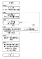
以下、第1実施形態の動作について図4を参照しながら詳述する。図4は、本実施形態に係る自動合焦装置の全体的な動作を表すフローチャートである。
【0024】
まず、ステップS301でメインスイッチ223の状態を検出し、オン状態であればステップS302へ進む。ここで、メインスイッチ223の機能はシステムに電源を投入することである。ステップS302では、記録媒体222の残容量を調べ、残容量が被写体を記録するのに充分であればステップS304へ進み、そうでなければステップS303へ進む。
【0025】
ステップS303では、記録媒体222の残容量が不充分であることを警告してステップS301に戻る。警告は、操作表示部216に表示するか又は図示しない音声出力部から警告音を出すか、又はその両方を行ってもよい。ステップS304では後述する図6のフローチャートに従ってフォーカスユニット205をリセットする。
【0026】
続くステップS305では、撮像素子209の撮影画面内での測距領域を表示する。すなわち、通常撮影時に設定された、図5の破線で示す撮影画面500内の中央付近にある測距領域501を、システム制御用CPU215に内蔵される図示しない演算メモリに記憶すると共に、操作表示部216に表示する。次のステップS306では、スイッチSW1の状態を調べ、オン状態であればステップS308へ進み、そうでなければステップS307へ進む。ここで、スイッチSW1の機能は、自動焦点機能(AF)や自動露出機能(AE)などの撮影スタンバイ動作を行うことである。ステップS307ではメインスイッチ223の状態を調べ、オン状態であればステップS305へ戻り、そうでなければステップS301へ戻る。
【0027】
ステップS308では、撮像素子209の出力信号から被写体輝度を算出し、ステップS309では、撮像素子209の出力信号から色情報検出部229により、測距領域501内の色情報と、撮像光学系201の色収差もしくは球面収差とによって被写体の高周波成分を抽出することにより検出された合焦位置から、最終的にどれだけ合焦位置をずらすべきかが決定される。
【0028】
その後のステップS310のAF動作では、ステップS309で求められたずらし量を用いて後述する図8のフローチャートに従ってAF動作を行う。この時、被写体輝度が所定値より低い場合には、補助光源228を被写体に向けて所定時間投光する。そして、ステップS311は、SW2の状態を調べ、オン状態であればステップS313へ進み、そうでなければステップS312へ進む。ここで、SW2の機能はSW1の操作後撮影を行うことである。ステップS312ではSW1の状態を調べ、オン状態であればステップS311へ戻り、そうでなければステップS305へ戻る。ステップS313では後述する図9のフローチャートに従って撮影動作を行う。ステップS314では記録媒体222の残容量を調べ、残容量が被写体を記録するのに充分であればステップS315へ進み、そうでなければステップS303へ進み、ステップS315ではSW2の状態を調べ、オン状態でなければステップS312へ進む。
【0029】
<フォーカスレンズのリセット>
次に、図6のフローチャートを参照しながら図4におけるステップS304のフォーカスレンズリセット動作について説明する。なお、図6は、図4におけるフォーカスレンズリセット動作(ステップS304)の処理を示すフローチャートである。本説明において、フォトインタラプタ206の位置と出力の関係を図7に示すようにフォーカスユニット205がフォトインタラプタ出力切り替え位置に対して無限端側にあるときは、フォトインタラプタ206の出力は“Lo”、至近端側にあるときは“Hi”になるものとする。
【0030】
まず、ステップS501では、フォトインタラプタ206の出力の状態を調べて、“Lo”であればステップS502へ進み、そうでなければステップS503へ進む。次のステップS502では、ステップS501でフォトインタラプタ206の出力によりフォーカスユニット205はフォトインタラプタ出力切り替え位置に対して無限端側にあると判断されるので、フォーカスユニット205を至近端側へ1ステップ移動する。
【0031】
ステップS503ではフォトインタラプタ206の出力の状態を調べ、“Hi”であればステップS504へ進み、そうでなければステップS505へ進む。ステップS504では、ステップS503でフォトインタラプタ206の出力によりフォーカスレンズ205はフォトインタラプタ出力切り替え位置に対して至近端側にあると判定されるので、フォーカスユニット205を無限端側へ1ステップ移動する。
【0032】
<フォーカスユニット205の動作>
次に、上述のようにフォーカスレンズをリセットした後のフォーカスユニット205の動作について説明する。
【0033】
まず、メインスイッチ223をオンにしたときのフォーカスユニット205の位置がフォトインタラプタ出力切り替え位置に対して無限端側にあった場合、フォトインタラプタ206の出力は“Lo”であるので、図6のステップS501、ステップS502によって、フォーカスユニット205はフォトインタラプタ206の出力が“Hi”になるまで至近端側へ1ステップずつ移動される。
【0034】
図7のフォトインタラプタ出力切り替え位置を越えたところでフォトインタラプタ206の出力は“Hi”に切り替わるので、今度は図6のステップS503、ステップS504に従ってフォトインタラプタ206の出力が“Lo”になるまで無限端側へ1ステップずつ移動される。
【0035】
こうして最終的にはフォーカスユニット205は、図7のリセット位置で止まる。
【0036】
メインスイッチ223をオンにしたときのフォーカスユニット205の位置がフォトインタラプタ出力切り替え位置に対して至近端側にあった場合は、無限端側へのみフォーカスユニット205を移動してフォトインタラプタ206の出力が“Lo”になったら止める。
【0037】
こうして前述のメインスイッチ223をオンにしたときのフォーカスユニット205の位置がフォトインタラプタ出力切り替え位置に対して無限端側にあった場合と同様に、最終的にはフォーカスユニット205は、図7のリセット位置に止まる。
【0038】
<第1実施形態のAF動作>
以下、図8のフローチャートを参照しながら図4のステップS310のAF動作のサブルーチンを説明する。
【0039】
このAF動作は、撮像素子209から得られる信号の高域成分(以下、焦点評価値と記す)のピーク検出により行われる。
【0040】
まず、ステップS601では、フォーカスユニット205をスキャン開始位置に移動する。ここではスキャン開始位置を測距範囲における無限端に設定するものとする。続くステップS602では、ステップS305で記憶した測距領域の焦点評価値とフォーカスユニット205の位置を記憶する。フォーカスユニット205の位置の検出は、フォーカスレンズ駆動モータ207にステッピングモータを用いている場合には、リセット位置検出用のフォトインタラプタ206によって検出されるリセット位置からの相対位置として検出される。
【0041】
ステップS603では、レンズ位置が終了位置にあるかどうかを調べ、終了位置であればステップS607へ進み、そうでなければステップS604へ進む。ここではスキャン終了位置を測距範囲における至近端に設定するものとする。ステップS604では、フォーカスユニット205を駆動して至近方向へ所定量動かす。
【0042】
その後のステップS607では、ステップS602で焦点評価値が最大値を示した位置から、色情報検出部229によりS309で求められた所定のずらし量だけ移動させた位置へフォーカスユニット205を移動する。
【0043】
<撮影動作の詳細>
次に、図9のフローチャートを参照しながら図4のステップS313の撮影動作のサブルーチンを説明する。
【0044】
図9は、図4の撮影動作(ステップS313)のサブルーチンを示すフローチャートである。
【0045】
まず、ステップS701では、被写体輝度を測定し、次のステップ702ではステップS701で測定した被写体輝度に応じて撮像素子209への露光を行う。続くステップS703では、前置処理回路211にて撮像素子209の出力ノイズ除去やA/D変換前に行う非線形処理などを行い、さらにステップS704では、前置処理回路211からのアナログ信号をデジタル信号に変換する。
【0046】
その後のステップS705では、A/D変換器212からの出力データを、メモリコントローラ214を介してバッファメモリ213内に一時的に格納し、そしてステップS706では、バッファメモリ213内のデータをメモリコントローラ214及び記録インターフェース221を介してカメラ本体に装着されたメモリカードなどの記録媒体222へ転送する。
【0047】
このように本実施形態では、被写体の測距領域内の色情報と撮像光学系の特性情報により、撮像光学系のズーム位置、絞り値、フォーカス位置、及び被写体の色温度ごとに、最適な測距方法を行うことができる。
【0048】
[第2実施形態]
以下、図10及び図11を参照しながら、本発明の自動合焦装置の第2実施形態について、第1実施形態と同様に電子カメラを適用した場合について説明する。
【0049】
図10に破線で示す領域501aがCPU215に測距領域として記憶されると共に、操作表示部216に表示される。図10は、本発明の第2実施形態に係る自動合焦装置の通常撮影時の測距領域を示す図である。
【0050】
本実施形態のように、測距領域501aが複数あることにより主被写体が撮影画面中央になくても、AFロックなどの手順を踏まずに主被写体に合焦することができ、かつ即写性を備えることができる。第2実施形態の自動合焦装置も図4のフローチャートに従って全体的な制御を行うが、第1実施形態と同じ動作を行う部分の説明は省略する。
【0051】
図4のステップS305において、撮像素子209の撮影画面内での測距領域は、図10の破線で示すような複数の測距領域501aとして、システム制御用CPU215に内蔵される図示しない演算メモリに記憶され且つ操作表示部216へ表示される。
【0052】
ステップS309では、色情報検出部229により、最終的にどれだけ合焦位置をずらすべきかが決定される。すなわち、撮像面における各測距領域501a内の色情報と、撮像光学系201の色収差もしくはそれぞれの測距領域501aの画角に対応する軸上又は軸外の結像特性である球面収差あるいは非点収差、コマ収差とによって被写体の高周波成分を抽出することにより検出された合焦位置から、最終的にどれだけ合焦位置をずらすべきかが決定される。
【0053】
<第2実施形態のAF動作>
ステップS310のAF動作では、ステップS309で求められたずらし量を用いて図11のフローチャートに従ってAF動作を行う。
【0054】
具体的に説明すると、まず、ステップS901では、フォーカスユニット205をスキャン開始位置に移動する。ここでは、スキャン開始位置を測距範囲における無限端に設定するものとする。続くステップS902では、ステップS305で記憶した全ての測距領域501aごとの焦点評価値とフォーカスユニット205の位置を記憶する。フォーカスユニット205の位置の検出は、フォーカスレンズ駆動モータ207にステッピングモータを用いている場合は、リセット位置検出用のフォトインタラプタ206によって検出されるリセット位置からの相対位置として検出される。
【0055】
次いでステップS903では、レンズ位置が終了位置にあるかどうかを調べ、終了位置であればステップS905へ進み、そうでなければステップS904へ進む。ここでは、スキャン終了位置を測距範囲における至近端に設定するものとする。
【0056】
ステップS904では、フォーカスユニット205を駆動して至近方向へ所定量動かし、ステップS905では、複数の測距領域501aごとにステップS902で記憶した焦点評価値の最大値を求め、その時のフォーカスユニット205の位置を抽出する。次のステップS906では、ステップS305で記憶した複数の測距領域501aについて、ステップS905で求めた焦点評価値の最大値とそのレンズ位置の組み合わせとから、合焦すべき測距領域を予め設定された演算により選択する。
【0057】
そして、ステップS907では、ステップS906で選択された測距領域において、焦点評価値が最大値を示した位置から、色情報検出部229によりステップS309で求められた所定のずらし量だけ移動させた位置へフォーカスユニット205を移動する。
【0058】
このように本実施形態のように測距領域が複数ある場合においても、被写体からの色情報と撮像光学系の特性情報を得ることにより、撮像光学系のズーム位置、絞り値、フォーカス位置、及び被写体の色温度ごとに最適な測距方法を行うことができる。
【0059】
なお、上述した図4、図6、図8、及び図9のフローチャートに従ったプログラムを例えばEEPROM218に格納し動作することにより、上述の制御方法を実現させることが可能となる。
【0060】
本発明は、上述した実施形態の装置に限定されず、複数の機器から構成されるシステムに適用しても、1つの機器から成る装置に適用してもよい。前述した実施形態の機能を実現するソフトウェアのプログラムコードを記憶した記憶媒体をシステムあるいは装置に供給し、そのシステムあるいは装置のコンピュータ(又はCPUやMPU)が記憶媒体に格納されたプログラムコードを読み出し実行することによっても、完成されることは言うまでもない。
【0061】
この場合、記憶媒体から読み出されたプログラムコード自体が前述した実施形態の機能を実現することになり、そのプログラムコードを記憶した記憶媒体は本発明を構成することになる。プログラムコードを供給するための記憶媒体としては、例えば、フロッピー(登録商標)ディスク、ハードディスク、光ディスク、光磁気ディスク、CD−ROM、CD−R、磁気テープ、不揮発性のメモリカード、ROMを用いることができる。また、コンピュータが読み出したプログラムコードを実行することにより、前述した実施形態の機能が実現されるだけではなく、そのプログラムコードの指示に基づき、コンピュータ上で稼動しているOSなどが実際の処理の一部又は全部を行い、その処理によって前述した実施形態の機能が実現される場合も含まれることは言うまでもない。
【0062】
さらに、記憶媒体から読み出されたプログラムコードが、コンピュータに挿入された機能拡張ボードやコンピュータに接続された機能拡張ユニットに備わるメモリに書き込まれた後、次のプログラムコードの指示に基づき、その拡張機能を拡張ボードや拡張ユニットに備わるCPUなどが処理を行って実際の処理の一部又は全部を行い、その処理によって前述した実施形態の機能が実現される場合も含まれることは言うまでもない。
[実施態様]
本発明の実施態様の例を以下に列挙する。
【0063】
<実施態様1> 被写体像の焦点調節を行うフォーカスレンズと、前記フォーカスレンズを駆動するフォーカスレンズ駆動手段と、前記フォーカスレンズによって結像された被写体像を受光して電気信号に変換する撮像素子と、前記撮像素子の受光面のうち、撮影画面上に設定された測距領域に対応する受光面の信号から、被写体の高周波成分を示す信号を抽出する抽出手段と、前記測距領域の色情報を検出する色情報検出手段と、前記抽出手段で抽出された信号に対して合焦位置を検出する合焦位置検出手段と、前記合焦位置検出手段の検出情報に基づいて、前記測距領域に対応する合焦位置に対し、前記色情報検出手段の検出情報及び/又は前記フォーカスレンズの特性情報により決まる所定の量だけずらした位置に、前記フォーカスレンズを駆動するように前記フォーカスレンズ駆動手段を制御する制御手段とを備えたことを特徴とする。
【0064】
<実施態様2> 前記測距領域の色温度ごとに前記ずらし量の設定を変化させることを特徴とする実施態様1に記載の自動合焦装置。
【0065】
<実施態様3> 前記測距領域の彩度あるいは色相ごとに前記ずらし量の設定を変化させることを特徴とする実施態様1に記載の自動合焦装置。
【0066】
<実施態様4> 前記フォーカスレンズのズーム位置ごとに前記ずらし量の設定を変化させることを特徴とする実施態様1に記載の自動合焦装置。
【0067】
<実施態様5> 前記フォーカスレンズの絞り値ごとに前記ずらし量の設定を変化させることを特徴とする実施態様1に記載の自動合焦装置。
【0068】
<実施態様6> 前記フォーカスレンズのフォーカス位置ごとに前記ずらし量の設定を変化させることを特徴とする実施態様1に記載の自動合焦装置。
【0069】
<実施態様7> 被写体像の焦点調節を行うフォーカスレンズと、前記フォーカスレンズを駆動するフォーカスレンズ駆動手段と、前記フォーカスレンズによって結像された被写体像を受光して電気信号に変換する撮像素子と、前記撮像素子の受光面のうち、撮影画面上に設定された複数の測距領域にそれぞれ対応する受光面の各信号から、被写体の高周波成分を示す信号をそれぞれ抽出する抽出手段と、前記各測距領域の色情報をそれぞれ検出する色情報検出手段と、前記抽出手段で抽出された各信号に対してそれぞれ合焦位置を検出する合焦位置検出手段と、前記合焦位置検出手段の検出情報に基づいて、合焦すべき測距領域を選択する合焦領域選択手段と、前記合焦領域選択手段により選択された測距領域に対応する合焦位置に対し、前記色情報検出手段の検出情報及び/又は前記フォーカスレンズの特性情報により決まる所定の量だけずらした位置に、前記フォーカスレンズを駆動するように前記フォーカスレンズ駆動手段を制御する制御手段とを有することを特徴とする自動合焦装置。
【0070】
<実施態様8> 前記各測距領域に対して、測距領域の色温度ごとに前記ずらし量の設定を変化させることを特徴とする実施態様7に記載の自動合焦装置。
【0071】
<実施態様9> 前記各測距領域に対して、測距領域の彩度あるいは色相ごとに前記ずらし量の設定を変化させることを特徴とする実施態様7に記載の自動合焦装置。
【0072】
<実施態様10> 前記各測距領域に対して、前記フォーカスレンズのズーム位置ごとに前記ずらし量の設定を変化させることを特徴とする実施態様7に記載の自動合焦装置。
【0073】
<実施態様11> 前記各測距領域に対して、前記フォーカスレンズの絞り値ごとに前記ずらし量の設定を変化させることを特徴とする実施態様7に記載の自動合焦装置。
【0074】
<実施態様12> 前記各測距領域に対して、前記フォーカスレンズのフォーカス位置ごとに前記ずらし量の設定を変化させることを特徴とする実施態様7に記載の自動合焦装置。
【0075】
<実施態様13> 被写体像の焦点調節を行うフォーカスレンズと、前記フォーカスレンズを駆動するフォーカスレンズ駆動手段と、前記フォーカスレンズによって結像された被写体像を受光して電気信号に変換する撮像素子とを有する自動合焦装置の制御方法において、前記撮像素子の受光面のうち、撮影画面上に設定された測距領域に対応する受光面の信号から、被写体の高周波成分を示す信号を抽出する抽出工程と、前記測距領域の色情報を検出する色情報検出工程と、前記抽出工程で抽出された信号に対して合焦位置を検出する合焦位置検出工程とを実行し、前記合焦位置検出工程の検出情報に基づいて、前記測距領域に対応する合焦位置に対し、前記色情報検出工程の検出情報及び/又は前記フォーカスレンズの特性情報により決まる所定の量だけずらした位置に、前記フォーカスレンズを駆動するように前記フォーカスレンズ駆動手段を制御することを特徴とする自動合焦装置の制御方法。
【0076】
<実施態様14> 被写体像の焦点調節を行うフォーカスレンズと、前記フォーカスレンズを駆動するフォーカスレンズ駆動手段と、前記フォーカスレンズによって結像された被写体像を受光して電気信号に変換する撮像素子とを有する自動合焦装置の制御方法において、前記撮像素子の受光面のうち、撮影画面上に設定された複数の測距領域にそれぞれ対応する受光面の各信号から、被写体の高周波成分を示す信号をそれぞれ抽出する抽出工程と、前記各測距領域の色情報をそれぞれ検出する色情報検出工程と、前記抽出工程で抽出された各信号に対してそれぞれ合焦位置を検出する合焦位置検出工程と、前記合焦位置検出工程の検出情報に基づいて、合焦すべき測距領域を選択する合焦領域選択工程とを実行し、前記合焦領域選択工程により選択された測距領域に対応する合焦位置に対し、前記色情報検出工程の検出情報及び/又は前記フォーカスレンズの特性情報により決まる所定の量だけずらした位置に、前記フォーカスレンズを駆動するように前記フォーカスレンズ駆動手段を制御することを特徴とする自動合焦装置の制御方法。
【0077】
<実施態様15> 被写体像の焦点調節を行うフォーカスレンズと、前記フォーカスレンズを駆動するフォーカスレンズ駆動手段と、前記フォーカスレンズによって結像された被写体像を受光して電気信号に変換する撮像素子とを有する自動合焦装置の制御方法を実行するための制御プログラムを提供する媒体であって、前記制御プログラムは、前記撮像素子の受光面のうち、撮影画面上に設定された測距領域に対応する受光面の信号から、被写体の高周波成分を示す信号を抽出する抽出ステップと、前記測距領域の色情報を検出する色情報検出ステップと、前記抽出ステップで抽出された信号に対して合焦位置を検出する合焦位置検出ステップと、前記合焦位置検出ステップの検出情報に基づいて、前記測距領域に対応する合焦位置に対し、前記色情報検出ステップの検出情報及び/又は前記フォーカスレンズの特性情報により決まる所定の量だけずらした位置に、前記フォーカスレンズを駆動するように前記フォーカスレンズ駆動手段を制御するステップを備えたことを特徴とする制御プログラムを提供する媒体。
【0078】
<実施態様16> 被写体像の焦点調節を行うフォーカスレンズと、前記フォーカスレンズを駆動するフォーカスレンズ駆動手段と、前記フォーカスレンズによって結像された被写体像を受光して電気信号に変換する撮像素子とを有する自動合焦装置の制御方法を実行するための制御プログラムを提供する媒体であって、前記制御プログラムは、前記撮像素子の受光面のうち、撮影画面上に設定された複数の測距領域にそれぞれ対応する受光面の各信号から、被写体の高周波成分を示す信号をそれぞれ抽出する抽出ステップと、前記各測距領域の色情報をそれぞれ検出する色情報検出ステップと、前記抽出ステップで抽出された各信号に対してそれぞれ合焦位置を検出する合焦位置検出ステップと、前記合焦位置検出ステップの検出情報に基づいて、合焦すべき測距領域を選択する合焦領域選択ステップと、前記合焦領域選択ステップにより選択された測距領域に対応する合焦位置に対し、前記色情報検出ステップの検出情報及び/又は前記フォーカスレンズの特性情報により決まる所定の量だけずらした位置に、前記フォーカスレンズを駆動するように前記フォーカスレンズ駆動手段を制御するステップを備えたことを特徴とする制御プログラムを提供する媒体。
【0079】
<実施態様17> 被写体像の焦点調節を行うフォーカスレンズと、前記フォーカスレンズを駆動するフォーカスレンズ駆動手段と、前記フォーカスレンズによって結像された被写体像を受光して電気信号に変換する撮像素子とを有する自動合焦装置の制御方法を実行するための制御プログラムであって、前記撮像素子の受光面のうち、撮影画面上に設定された測距領域に対応する受光面の信号から、被写体の高周波成分を示す信号を抽出する抽出ステップと、前記測距領域の色情報を検出する色情報検出ステップと、前記抽出ステップで抽出された信号に対して合焦位置を検出する合焦位置検出ステップと、前記合焦位置検出ステップの検出情報に基づいて、前記測距領域に対応する合焦位置に対し、前記色情報検出ステップの検出情報及び/又は前記フォーカスレンズの特性情報により決まる所定の量だけずらした位置に、前記フォーカスレンズを駆動するように前記フォーカスレンズ駆動手段を制御するステップを備えたことを特徴とする制御プログラム。
【0080】
<実施態様18> 被写体像の焦点調節を行うフォーカスレンズと、前記フォーカスレンズを駆動するフォーカスレンズ駆動手段と、前記フォーカスレンズによって結像された被写体像を受光して電気信号に変換する撮像素子とを有する自動合焦装置の制御方法を実行するための制御プログラムを提供する媒体であって、前記撮像素子の受光面のうち、撮影画面上に設定された複数の測距領域にそれぞれ対応する受光面の各信号から、被写体の高周波成分を示す信号をそれぞれ抽出する抽出ステップと、前記各測距領域の色情報をそれぞれ検出する色情報検出ステップと、前記抽出ステップで抽出された各信号に対してそれぞれ合焦位置を検出する合焦位置検出ステップと、前記合焦位置検出ステップの検出情報に基づいて、合焦すべき測距領域を選択する合焦領域選択ステップと、前記合焦領域選択ステップにより選択された測距領域に対応する合焦位置に対し、前記色情報検出ステップの検出情報及び/又は前記フォーカスレンズの特性情報により決まる所定の量だけずらした位置に、前記フォーカスレンズを駆動するように前記フォーカスレンズ駆動手段を制御するステップを備えたことを特徴とする制御プログラム。
【0081】
【発明の効果】
以上説明したように本発明では、被写体の持つ最適な測距方法をフィードバック可能な系で実行することができ、合焦精度の向上を実現することが可能になる。
【図面の簡単な説明】
【図1】本発明を適用した電子カメラの構成ブロック図である。
【図2】撮像素子の画素構成の例を示す図である。
【図3】人間の目の視感度特性を表す図である。
【図4】第1実施形態の全体動作を表すフローチャートである。
【図5】第1実施形態の測距領域を示す図である。
【図6】フォーカスレンズのリセット動作を表すフローチャートである。
【図7】フォトインタラプタの位置と出力の関係を表す図である。
【図8】第1実施形態に係るAF動作を示すフローチャートである。
【図9】撮影動作を示すフローチャートである。
【図10】本発明の第2実施形態の測距領域を示す図である。
【図11】第2実施形態に係るAF動作を示すフローチャートである。
【符号の説明】
201 撮像光学系
202 絞り及びシャッタ
203 モータ
204 メカ駆動回路
205 フォーカスユニット
206 フォトインタラプタ
207 モータ
208 フォーカスレンズ駆動回路
209 撮像素子
210 タイミング信号処理回路
211 前置処理回路
212 A/D変換器
213 バッファメモリ
214 メモリコントローラ
215 マイクロコントローラ
216 操作表示部
217 操作部
218 不揮発性メモリ
219 インターフェース
220 拡張ユニット
221 インターフェース
222 記録媒体
223 メインスイッチ
224 スイッチ
225 撮影スイッチ
226 モードスイッチ
227 フラッシュ
228 補助光源
229 色情報検出部[0001]
TECHNICAL FIELD OF THE INVENTION
The present invention relates to an automatic focusing device, and more particularly to an automatic focusing device used for an electronic still camera, a video camera, and the like.
[0002]
[Prior art]
2. Description of the Related Art Conventionally, in an electronic still camera, a video camera, or the like, an automatic focus detection device that performs signal processing on a high-frequency component of a luminance signal obtained from an imaging device such as a CCD and performs a focusing operation has been used. In this automatic focus detection apparatus, it is common to detect a lens position having the highest contrast and obtain a focal point by integrating a high-frequency component of a signal in a ranging area set in each screen. I have.
[0003]
Also, an automatic focus detection device that corrects a shift amount of a focus detection position due to chromatic aberration of a focus detection light receiving sensor has been proposed (for example, see Patent Document 1). In this device, a correction unit for calculating a correction value for correcting a detection error caused by chromatic aberration of a focus detection light receiving sensor, and a focus detection unit for detecting a focus adjustment state of a photographing lens are provided, and the focus detection unit Based on the output of the correction unit and the output of the correction unit, control is performed to drive the photographing lens.
[0004]
[Patent Document 1]
JP 2000-266988 A
[0005]
[Problems to be solved by the invention]
However, the conventional example has the following problems.
[0006]
(1) In the case of the integration-type focus detection method, there is a problem that the focus position is not always optimal due to the color and color temperature of the subject and the characteristics of the imaging optical system, particularly chromatic aberration. Was. In order to solve this, a method of selecting an optimal color pixel from the pixels of the image sensor used for focus detection based on color information of the subject can be considered, but the color of the subject that can be handled is limited. However, since only some of the pixels are used, sampling becomes coarse, and there is a problem that it is impossible to cope with a subject having a high frequency component.
[0007]
(2) In Japanese Patent Application Laid-Open No. H11-157, the correction affects a characteristic that is not an original aberration of the imaging optical system, such as chromatic aberration of the optical system for collecting light to the light receiving sensor. Since it is not a feedback system using its own signal, there is a problem that the mounting accuracy of the light receiving sensor itself affects the focusing accuracy. Further, correction of a shift amount due to a difference in color temperature or color of a subject is not taken into consideration, and there is still room for improvement from the viewpoint of improving focusing accuracy.
[0008]
The present invention has been made in view of the above-described conventional problems, and an object of the present invention is to provide an automatic focusing device that realizes an improvement in focusing accuracy by enabling an optimal distance measuring method of a subject to be performed by a system capable of feeding back. .
[0009]
[Means for Solving the Problems]
In order to achieve the above object, an automatic focusing apparatus according to the present invention includes a focus lens for adjusting a focus of a subject image, a focus lens driving unit for driving the focus lens, and a subject image formed by the focus lens. An image sensor that receives light and converts it into an electric signal, and extracts a signal indicating a high-frequency component of a subject from a signal of a light receiving surface corresponding to a distance measurement area set on a shooting screen among light receiving surfaces of the image sensor. Extraction means for detecting the color information of the distance measurement area, color information detection means for detecting color information of the distance measurement area, focus position detection means for detecting a focus position with respect to a signal extracted by the extraction means, and detection of the focus position Based on the detection information of the means, a predetermined amount determined by the detection information of the color information detection means and / or the characteristic information of the focus lens with respect to the focus position corresponding to the distance measurement area. The shifting position, characterized in that a control means for controlling the focus lens driving means to drive the focus lens.
[0010]
BEST MODE FOR CARRYING OUT THE INVENTION
Hereinafter, embodiments of the present invention will be described with reference to the drawings.
[0011]
[First Embodiment]
<Configuration of electronic camera>
FIG. 1 is a block diagram showing a configuration of an electronic camera applied to the automatic focusing device according to the first embodiment of the present invention.
[0012]
In FIG. 1,
[0013]
[0014]
[0015]
[0016]
Reference numeral 229 denotes a color information detection unit for detecting color information in the distance measurement area. The color information detection unit 229 obtains information on the color of the subject itself or the color temperature of the light source from the RGB values obtained from the video signal. From the in-focus position detected by extracting the high-frequency component of the subject based on the above characteristic information, how much the in-focus position should be finally shifted is determined.
[0017]
<Pixel configuration of
FIG. 2 is a diagram illustrating an example of a pixel configuration of the
[0018]
Here, in the image sensor of FIG. 2A, pixels having spectral sensitivities of R (red), G (green), and B (blue) are configured as shown in FIG. In the imaging device of (1), pixels having spectral sensitivities of M (magenta), G (green), C (cyan), and Y (yellow) are arranged as shown in FIG.
[0019]
When the image pickup device of FIG. 2A is used, a luminance signal representing information of high-definition details of an image captured by these image pickup devices is a signal obtained by reading out only the G pixel of FIG. A color difference signal obtained by performing a matrix process on a signal from which pixels are sequentially read out is used as a correction signal, and is made up of a sum of the correction signal and a signal obtained by adding a fixed ratio to a captured image.
[0020]
When the image sensor of FIG. 2B is used, a signal obtained by sequentially reading all the pixels of FIG. 2B and a color difference signal obtained by performing matrix processing on the signal of sequentially reading all the pixels are used as correction signals. The correction signal is composed of the sum of a signal obtained by adding a fixed ratio to the photographed image, and finally has a characteristic having a spectral sensitivity close to the visibility characteristic of human eyes as shown in FIG.
[0021]
On the other hand, the signal used for focus position detection is a signal obtained by sequentially reading out all the pixels in any of the image pickup devices of FIGS. 2A and 2B, so that the spectral sensitivity characteristic becomes a luminance signal. In comparison, the sensitivity is higher than the luminance signal on the short wavelength side and the long wavelength side of the visibility range.
[0022]
As described above, in the automatic focusing apparatus according to the present embodiment, since the imaging
[0023]
<Overall operation of automatic focusing device>
Hereinafter, the operation of the first embodiment will be described in detail with reference to FIG. FIG. 4 is a flowchart illustrating the overall operation of the automatic focusing apparatus according to the present embodiment.
[0024]
First, in step S301, the state of the
[0025]
In step S303, a warning is issued that the remaining capacity of the
[0026]
In a succeeding step S305, a distance measurement area in a shooting screen of the
[0027]
In step S308, the luminance of the subject is calculated from the output signal of the
[0028]
In the subsequent AF operation in step S310, the AF operation is performed according to the flowchart of FIG. 8 described later using the shift amount obtained in step S309. At this time, if the subject brightness is lower than the predetermined value, the auxiliary
[0029]
<Resetting the focus lens>
Next, the focus lens reset operation in step S304 in FIG. 4 will be described with reference to the flowchart in FIG. FIG. 6 is a flowchart showing the processing of the focus lens reset operation (step S304) in FIG. In this description, when the
[0030]
First, in step S501, the state of the output of the
[0031]
In step S503, the state of the output of the
[0032]
<Operation of
Next, the operation of the
[0033]
First, when the position of the
[0034]
Since the output of the photo-
[0035]
Thus, finally, the
[0036]
If the position of the
[0037]
In the same manner as in the case where the position of the
[0038]
<AF Operation of First Embodiment>
Hereinafter, the subroutine of the AF operation in step S310 in FIG. 4 will be described with reference to the flowchart in FIG.
[0039]
This AF operation is performed by detecting a peak of a high-frequency component (hereinafter, referred to as a focus evaluation value) of a signal obtained from the
[0040]
First, in step S601, the
[0041]
In step S603, it is checked whether the lens position is at the end position. If the lens position is the end position, the process proceeds to step S607; otherwise, the process proceeds to step S604. Here, it is assumed that the scan end position is set to the closest end in the distance measurement range. In step S604, the
[0042]
In subsequent step S607, the
[0043]
<Details of shooting operation>
Next, a subroutine of the photographing operation in step S313 in FIG. 4 will be described with reference to the flowchart in FIG.
[0044]
FIG. 9 is a flowchart showing a subroutine of the photographing operation (step S313) of FIG.
[0045]
First, in step S701, the subject brightness is measured, and in the
[0046]
In the subsequent step S705, the output data from the A /
[0047]
As described above, in the present embodiment, the optimal measurement for each of the zoom position, the aperture value, the focus position, and the color temperature of the subject is performed based on the color information in the ranging area of the subject and the characteristic information of the imaging optical system. Distance method can be performed.
[0048]
[Second embodiment]
Hereinafter, a second embodiment of the automatic focusing apparatus according to the present invention will be described with reference to FIGS. 10 and 11, in which an electronic camera is applied in the same manner as the first embodiment.
[0049]
An
[0050]
As in the present embodiment, even when the main subject is not located at the center of the shooting screen, the main subject can be focused without performing a procedure such as AF lock because of the plurality of ranging
[0051]
In step S305 in FIG. 4, the distance measurement area in the shooting screen of the
[0052]
In step S309, the color information detection unit 229 finally determines how much the focus position should be shifted. That is, the color information in each of the
[0053]
<AF Operation of Second Embodiment>
In the AF operation in step S310, the AF operation is performed according to the flowchart in FIG. 11 using the shift amount obtained in step S309.
[0054]
Specifically, first, in step S901, the
[0055]
Next, in step S903, it is determined whether the lens position is at the end position. If the lens position is the end position, the process proceeds to step S905; otherwise, the process proceeds to step S904. Here, it is assumed that the scan end position is set to the nearest end in the distance measurement range.
[0056]
In step S904, the
[0057]
Then, in step S907, in the distance measurement area selected in step S906, a position shifted by the predetermined shift amount obtained in step S309 by the color information detection unit 229 from the position where the focus evaluation value shows the maximum value. The
[0058]
As described above, even when there are a plurality of ranging areas as in the present embodiment, by obtaining color information from the subject and characteristic information of the imaging optical system, the zoom position, the aperture value, the focus position, and the An optimal distance measuring method can be performed for each color temperature of a subject.
[0059]
The above-described control method can be realized by storing a program in accordance with the flowcharts of FIGS. 4, 6, 8, and 9 in, for example, the
[0060]
The present invention is not limited to the device of the above-described embodiment, and may be applied to a system including a plurality of devices or an apparatus including one device. A storage medium storing program codes of software for realizing the functions of the above-described embodiments is supplied to a system or apparatus, and a computer (or CPU or MPU) of the system or apparatus reads out and executes the program code stored in the storage medium. It goes without saying that it will be completed by doing so.
[0061]
In this case, the program code itself read from the storage medium realizes the function of the above-described embodiment, and the storage medium storing the program code constitutes the present invention. As a storage medium for supplying the program code, for example, a floppy (registered trademark) disk, hard disk, optical disk, magneto-optical disk, CD-ROM, CD-R, magnetic tape, nonvolatile memory card, or ROM is used. Can be. When the computer executes the readout program code, not only the functions of the above-described embodiment are realized, but also the OS or the like running on the computer performs the actual processing based on the instruction of the program code. It goes without saying that a case where some or all of the functions are performed and the functions of the above-described embodiments are realized by the processing is also included.
[0062]
Further, after the program code read from the storage medium is written to a memory provided in a function expansion board inserted into the computer or a function expansion unit connected to the computer, the expansion is performed based on the instruction of the next program code. It goes without saying that the CPU of the expansion board or the expansion unit performs the processing and performs part or all of the actual processing, and the processing realizes the functions of the above-described embodiments.
[Embodiment]
Examples of embodiments of the present invention are listed below.
[0063]
<First Embodiment> A focus lens that adjusts the focus of a subject image, a focus lens driving unit that drives the focus lens, and an imaging device that receives the subject image formed by the focus lens and converts the subject image into an electric signal Extracting means for extracting a signal indicating a high-frequency component of a subject from a signal of a light receiving surface corresponding to a distance measuring area set on a shooting screen, of the light receiving surface of the image sensor, and color information of the distance measuring area Color information detecting means for detecting the focus detection position, a focus position detecting means for detecting a focus position with respect to the signal extracted by the extracting means, and the distance measuring area based on the detection information of the focus position detecting means. The focus lens is shifted by a predetermined amount determined by the detection information of the color information detecting means and / or the characteristic information of the focus lens from the focus position corresponding to the focus lens. And control means for controlling the focus lens driving means so as to drive the lens.
[0064]
<Second Embodiment> The automatic focusing apparatus according to the first embodiment, wherein the setting of the shift amount is changed for each color temperature of the distance measurement area.
[0065]
<
[0066]
<Embodiment 4> The automatic focusing apparatus according to
[0067]
<Embodiment 5> The automatic focusing apparatus according to
[0068]
<Sixth Embodiment> The automatic focusing device according to the first embodiment, wherein the setting of the shift amount is changed for each focus position of the focus lens.
[0069]
<Embodiment 7> A focus lens that adjusts the focus of a subject image, a focus lens driving unit that drives the focus lens, and an image sensor that receives the subject image formed by the focus lens and converts it into an electric signal Extracting means for extracting a signal indicating a high-frequency component of a subject from each signal of a light receiving surface corresponding to each of a plurality of distance measurement areas set on a shooting screen among light receiving surfaces of the image sensor; Color information detection means for detecting color information of the distance measurement area, focus position detection means for detecting a focus position with respect to each signal extracted by the extraction means, and detection of the focus position detection means A focusing area selecting means for selecting a ranging area to be focused on the basis of the information; and a focusing position corresponding to the ranging area selected by the focusing area selecting means. Control means for controlling the focus lens driving means so as to drive the focus lens at a position shifted by a predetermined amount determined by the detection information of the color information detection means and / or the characteristic information of the focus lens. An automatic focusing device characterized by the following.
[0070]
<Eighth Embodiment> The automatic focusing apparatus according to the seventh embodiment, wherein the setting of the shift amount is changed for each of the distance measurement areas for each color temperature of the distance measurement area.
[0071]
<Embodiment 9> The automatic focusing apparatus according to embodiment 7, wherein the setting of the shift amount is changed for each of the distance measurement areas for each saturation or hue of the distance measurement area.
[0072]
<Embodiment 10> The automatic focusing apparatus according to embodiment 7, wherein the setting of the shift amount is changed for each of the distance measurement areas for each zoom position of the focus lens.
[0073]
<
[0074]
<Twelfth Embodiment> The automatic focusing apparatus according to a seventh embodiment, wherein the setting of the shift amount is changed for each focus position of the focus lens for each of the distance measurement areas.
[0075]
<Thirteenth Embodiment> A focus lens that adjusts the focus of a subject image, a focus lens driving unit that drives the focus lens, and an imaging device that receives the subject image formed by the focus lens and converts it into an electric signal Extracting a signal indicating a high-frequency component of a subject from a signal on a light receiving surface corresponding to a distance measurement area set on a photographing screen among light receiving surfaces of the image pickup device. Performing a focus information detecting step of detecting a focus position with respect to the signal extracted in the extracting step; Based on the detection information in the detection step, a focus position corresponding to the distance measurement area is determined by the detection information in the color information detection step and / or the characteristic information of the focus lens. Controlling the focus lens driving means so as to drive the focus lens to a position shifted by a predetermined amount.
[0076]
Embodiment 14 A focus lens for adjusting the focus of a subject image, a focus lens driving unit for driving the focus lens, and an image sensor for receiving the subject image formed by the focus lens and converting the image into an electric signal A signal indicating a high-frequency component of a subject from signals of light-receiving surfaces respectively corresponding to a plurality of distance measurement areas set on a photographing screen among light-receiving surfaces of the image pickup device. An extraction step of extracting color information of each of the distance measurement areas, and a focus position detection step of detecting a focus position of each signal extracted in the extraction step. And a focusing area selecting step of selecting a ranging area to be focused based on the detection information of the focusing position detecting step. The focus lens is driven to a position shifted by a predetermined amount determined by the detection information of the color information detection step and / or the characteristic information of the focus lens with respect to the focus position corresponding to the selected distance measurement area. Controlling the focus lens driving means as described above.
[0077]
Embodiment 15 A focus lens for adjusting the focus of a subject image, a focus lens driving unit for driving the focus lens, and an image sensor for receiving the subject image formed by the focus lens and converting it into an electric signal A medium for providing a control program for executing a control method of an automatic focusing apparatus, the control program corresponding to a distance measurement area set on a shooting screen in a light receiving surface of the image sensor. An extraction step of extracting a signal indicating a high-frequency component of a subject from a signal of a light receiving surface to be detected, a color information detection step of detecting color information of the ranging area, and focusing on the signal extracted in the extraction step. A focus position detection step of detecting a position, and a focus position corresponding to the distance measurement area, based on detection information of the focus position detection step, Controlling the focus lens driving means to drive the focus lens at a position shifted by a predetermined amount determined by the detection information of the color information detection step and / or the characteristic information of the focus lens. A medium that provides a featured control program.
[0078]
Embodiment 16 A focus lens that adjusts the focus of a subject image, a focus lens driving unit that drives the focus lens, and an image sensor that receives the subject image formed by the focus lens and converts it into an electric signal A control program for executing a control method of an automatic focusing apparatus, the control program comprising: a plurality of distance measurement areas set on a shooting screen in a light receiving surface of the image sensor; From each signal of the light receiving surface corresponding to each, the extraction step of extracting the signal indicating the high frequency component of the subject, the color information detection step of detecting the color information of each of the distance measurement areas, and the extraction step A focus position detecting step of detecting a focus position with respect to each of the obtained signals, and A focusing area selecting step of selecting a ranging area to be focused; detecting information of the color information detecting step with respect to a focusing position corresponding to the ranging area selected by the focusing area selecting step; And / or a step of controlling the focus lens driving means so as to drive the focus lens at a position shifted by a predetermined amount determined by the characteristic information of the focus lens. .
[0079]
<Embodiment 17> A focus lens that adjusts the focus of a subject image, a focus lens driving unit that drives the focus lens, and an imaging device that receives the subject image formed by the focus lens and converts it into an electric signal A control program for executing the control method of the automatic focusing device having a light receiving surface of the imaging device, from a signal of a light receiving surface corresponding to a distance measurement area set on a shooting screen, of a light receiving surface of the image sensor. An extraction step of extracting a signal indicating a high-frequency component; a color information detection step of detecting color information of the ranging area; and a focus position detection step of detecting a focus position with respect to the signal extracted in the extraction step. And, based on the detection information of the in-focus position detection step, for the in-focus position corresponding to the ranging area, the detection information of the color information detection step and And / or controlling the focus lens driving means so as to drive the focus lens at a position shifted by a predetermined amount determined by characteristic information of the focus lens.
[0080]
Embodiment 18 A focus lens that adjusts the focus of a subject image, a focus lens driving unit that drives the focus lens, and an imaging device that receives the subject image formed by the focus lens and converts it into an electric signal A medium for providing a control program for executing a control method of an automatic focusing apparatus having a light receiving surface corresponding to a plurality of distance measurement areas set on a shooting screen on a light receiving surface of the image sensor. From each signal of the surface, an extraction step of extracting a signal indicating a high-frequency component of the subject, a color information detection step of detecting color information of each of the distance measurement areas, and a signal extraction step. A focusing position detecting step of detecting a focusing position, and a distance measuring area to be focused based on the detection information of the focusing position detecting step. A focus area selecting step of selecting a region, and detection information of the color information detecting step and / or characteristic information of the focus lens with respect to a focus position corresponding to the focusing area selected in the focus area selecting step. Controlling the focus lens driving means so as to drive the focus lens at a position shifted by a predetermined amount determined by the control program.
[0081]
【The invention's effect】
As described above, according to the present invention, the optimal distance measurement method of the subject can be executed by a system capable of feeding back, and it is possible to improve the focusing accuracy.
[Brief description of the drawings]
FIG. 1 is a configuration block diagram of an electronic camera to which the present invention is applied.
FIG. 2 is a diagram illustrating an example of a pixel configuration of an image sensor.
FIG. 3 is a diagram illustrating visibility characteristics of human eyes.
FIG. 4 is a flowchart illustrating an overall operation of the first embodiment.
FIG. 5 is a diagram illustrating a ranging area according to the first embodiment.
FIG. 6 is a flowchart illustrating a reset operation of the focus lens.
FIG. 7 is a diagram illustrating a relationship between a position of a photo interrupter and an output.
FIG. 8 is a flowchart illustrating an AF operation according to the first embodiment.
FIG. 9 is a flowchart illustrating a photographing operation.
FIG. 10 is a diagram illustrating a ranging area according to a second embodiment of the present invention.
FIG. 11 is a flowchart illustrating an AF operation according to the second embodiment.
[Explanation of symbols]
201 Imaging optical system
202 Aperture and shutter
203 motor
204 Mechanical drive circuit
205 Focus unit
206 Photointerrupter
207 motor
208 Focus lens drive circuit
209 Image sensor
210 Timing signal processing circuit
211 Pre-processing circuit
212 A / D converter
213 Buffer memory
214 Memory controller
215 Microcontroller
216 Operation display
217 Operation unit
218 Non-volatile memory
219 Interface
220 Expansion unit
221 interface
222 recording medium
223 Main switch
224 switch
225 Shooting switch
226 Mode switch
227 Flash
228 Auxiliary light source
229 Color information detector
Claims (1)
前記フォーカスレンズを駆動するフォーカスレンズ駆動手段と、
前記フォーカスレンズによって結像された被写体像を受光して電気信号に変換する撮像素子と、
前記撮像素子の受光面のうち、撮影画面上に設定された測距領域に対応する受光面の信号から、被写体の高周波成分を示す信号を抽出する抽出手段と、
前記測距領域の色情報を検出する色情報検出手段と、
前記抽出手段で抽出された信号に対して合焦位置を検出する合焦位置検出手段と、
前記合焦位置検出手段の検出情報に基づいて、前記測距領域に対応する合焦位置に対し、前記色情報検出手段の検出情報及び/又は前記フォーカスレンズの特性情報により決まる所定の量だけずらした位置に、前記フォーカスレンズを駆動するように前記フォーカスレンズ駆動手段を制御する制御手段とを備えたことを特徴とする自動合焦装置。A focus lens for adjusting the focus of the subject image,
Focus lens driving means for driving the focus lens;
An image sensor that receives a subject image formed by the focus lens and converts it into an electric signal;
From the light receiving surface of the image sensor, from the signal of the light receiving surface corresponding to the distance measurement area set on the shooting screen, extraction means for extracting a signal indicating a high frequency component of the subject,
Color information detection means for detecting color information of the distance measurement area,
Focus position detection means for detecting a focus position with respect to the signal extracted by the extraction means,
On the basis of the detection information of the focus position detection means, the focus position corresponding to the distance measurement area is shifted by a predetermined amount determined by the detection information of the color information detection means and / or the characteristic information of the focus lens. And a control means for controlling the focus lens driving means so as to drive the focus lens at a position where the focus lens is driven.
Priority Applications (1)
| Application Number | Priority Date | Filing Date | Title |
|---|---|---|---|
| JP2003141655A JP4532849B2 (en) | 2003-05-20 | 2003-05-20 | Automatic focusing device |
Applications Claiming Priority (1)
| Application Number | Priority Date | Filing Date | Title |
|---|---|---|---|
| JP2003141655A JP4532849B2 (en) | 2003-05-20 | 2003-05-20 | Automatic focusing device |
Publications (3)
| Publication Number | Publication Date |
|---|---|
| JP2004347665A true JP2004347665A (en) | 2004-12-09 |
| JP2004347665A5 JP2004347665A5 (en) | 2006-07-06 |
| JP4532849B2 JP4532849B2 (en) | 2010-08-25 |
Family
ID=33529955
Family Applications (1)
| Application Number | Title | Priority Date | Filing Date |
|---|---|---|---|
| JP2003141655A Expired - Fee Related JP4532849B2 (en) | 2003-05-20 | 2003-05-20 | Automatic focusing device |
Country Status (1)
| Country | Link |
|---|---|
| JP (1) | JP4532849B2 (en) |
Cited By (14)
| Publication number | Priority date | Publication date | Assignee | Title |
|---|---|---|---|---|
| JP2006072016A (en) * | 2004-09-02 | 2006-03-16 | Victor Co Of Japan Ltd | Autofocus device |
| JP2006293035A (en) * | 2005-04-11 | 2006-10-26 | Canon Inc | Imaging apparatus, focusing device and its control method |
| JP2007047415A (en) * | 2005-08-09 | 2007-02-22 | Canon Inc | Imaging apparatus and focus adjusting device |
| JP2007156304A (en) * | 2005-12-08 | 2007-06-21 | Canon Inc | Camera, camera system, and interchangeable lens device |
| JP2007333858A (en) * | 2006-06-13 | 2007-12-27 | Canon Inc | Optical equipment |
| JP2011007882A (en) * | 2009-06-23 | 2011-01-13 | Nikon Corp | Imaging apparatus |
| WO2011007869A1 (en) * | 2009-07-17 | 2011-01-20 | 株式会社ニコン | Focusing device and camera |
| JP2014048620A (en) * | 2012-09-04 | 2014-03-17 | Canon Inc | Focus adjustment device, control method therefor, and control program |
| US9131142B2 (en) | 2009-07-17 | 2015-09-08 | Nikon Corporation | Focusing device and camera |
| JP2015222411A (en) * | 2014-05-01 | 2015-12-10 | キヤノン株式会社 | Image-capturing device and control method thereof |
| US10015386B2 (en) | 2014-09-09 | 2018-07-03 | Canon Kabushiki Kaisha | Focus control apparatus, image capturing apparatus, interchangeable lens, focus control method, and storage medium storing focus control program |
| JP2019095803A (en) * | 2019-02-06 | 2019-06-20 | キヤノン株式会社 | Focus detection device, imaging device, and focus detection method |
| US10425571B2 (en) * | 2016-03-10 | 2019-09-24 | Canon Kabushiki Kaisha | Focusing and image pickup apparatus, storage medium, and method for controlling positioning of a focus lens |
| JP2020074022A (en) * | 2020-01-14 | 2020-05-14 | キヤノン株式会社 | Lens, transmitter, and receiver |
Families Citing this family (1)
| Publication number | Priority date | Publication date | Assignee | Title |
|---|---|---|---|---|
| JP2011176715A (en) * | 2010-02-25 | 2011-09-08 | Nikon Corp | Back-illuminated image sensor and imaging apparatus |
Citations (11)
| Publication number | Priority date | Publication date | Assignee | Title |
|---|---|---|---|---|
| JPS5859413A (en) * | 1981-10-06 | 1983-04-08 | Olympus Optical Co Ltd | Autofocusing method |
| JPS5886504A (en) * | 1981-11-18 | 1983-05-24 | Nippon Kogaku Kk <Nikon> | Focus detector |
| JPS62227108A (en) * | 1986-03-28 | 1987-10-06 | Nikon Corp | Focus detecting device |
| JPS63296479A (en) * | 1988-03-31 | 1988-12-02 | Minolta Camera Co Ltd | Image sensing system |
| JPH04190220A (en) * | 1990-11-22 | 1992-07-08 | Asahi Optical Co Ltd | Camera system |
| JPH0545574A (en) * | 1991-08-14 | 1993-02-23 | Sony Corp | Video camera |
| JPH116952A (en) * | 1998-05-12 | 1999-01-12 | Nikon Corp | Automatic focusing device for camera |
| JP2000266988A (en) * | 1999-03-16 | 2000-09-29 | Olympus Optical Co Ltd | Electronic camera |
| JP2002372661A (en) * | 2001-06-15 | 2002-12-26 | Fuji Photo Optical Co Ltd | Photographic lens |
| JP2003114369A (en) * | 2001-10-03 | 2003-04-18 | Sony Corp | Image pickup device |
| JP2003143618A (en) * | 2001-11-06 | 2003-05-16 | Canon Inc | Color separation optical system and image pickup device employing the same |
-
2003
- 2003-05-20 JP JP2003141655A patent/JP4532849B2/en not_active Expired - Fee Related
Patent Citations (11)
| Publication number | Priority date | Publication date | Assignee | Title |
|---|---|---|---|---|
| JPS5859413A (en) * | 1981-10-06 | 1983-04-08 | Olympus Optical Co Ltd | Autofocusing method |
| JPS5886504A (en) * | 1981-11-18 | 1983-05-24 | Nippon Kogaku Kk <Nikon> | Focus detector |
| JPS62227108A (en) * | 1986-03-28 | 1987-10-06 | Nikon Corp | Focus detecting device |
| JPS63296479A (en) * | 1988-03-31 | 1988-12-02 | Minolta Camera Co Ltd | Image sensing system |
| JPH04190220A (en) * | 1990-11-22 | 1992-07-08 | Asahi Optical Co Ltd | Camera system |
| JPH0545574A (en) * | 1991-08-14 | 1993-02-23 | Sony Corp | Video camera |
| JPH116952A (en) * | 1998-05-12 | 1999-01-12 | Nikon Corp | Automatic focusing device for camera |
| JP2000266988A (en) * | 1999-03-16 | 2000-09-29 | Olympus Optical Co Ltd | Electronic camera |
| JP2002372661A (en) * | 2001-06-15 | 2002-12-26 | Fuji Photo Optical Co Ltd | Photographic lens |
| JP2003114369A (en) * | 2001-10-03 | 2003-04-18 | Sony Corp | Image pickup device |
| JP2003143618A (en) * | 2001-11-06 | 2003-05-16 | Canon Inc | Color separation optical system and image pickup device employing the same |
Cited By (17)
| Publication number | Priority date | Publication date | Assignee | Title |
|---|---|---|---|---|
| JP2006072016A (en) * | 2004-09-02 | 2006-03-16 | Victor Co Of Japan Ltd | Autofocus device |
| JP2006293035A (en) * | 2005-04-11 | 2006-10-26 | Canon Inc | Imaging apparatus, focusing device and its control method |
| JP4700993B2 (en) * | 2005-04-11 | 2011-06-15 | キヤノン株式会社 | Imaging device |
| JP2007047415A (en) * | 2005-08-09 | 2007-02-22 | Canon Inc | Imaging apparatus and focus adjusting device |
| JP2007156304A (en) * | 2005-12-08 | 2007-06-21 | Canon Inc | Camera, camera system, and interchangeable lens device |
| JP2007333858A (en) * | 2006-06-13 | 2007-12-27 | Canon Inc | Optical equipment |
| JP2011007882A (en) * | 2009-06-23 | 2011-01-13 | Nikon Corp | Imaging apparatus |
| US9749518B2 (en) | 2009-07-17 | 2017-08-29 | Nikon Corporation | Focusing device and camera |
| WO2011007869A1 (en) * | 2009-07-17 | 2011-01-20 | 株式会社ニコン | Focusing device and camera |
| US9131142B2 (en) | 2009-07-17 | 2015-09-08 | Nikon Corporation | Focusing device and camera |
| US10237470B2 (en) | 2009-07-17 | 2019-03-19 | Nikon Corporation | Focusing device and camera |
| JP2014048620A (en) * | 2012-09-04 | 2014-03-17 | Canon Inc | Focus adjustment device, control method therefor, and control program |
| JP2015222411A (en) * | 2014-05-01 | 2015-12-10 | キヤノン株式会社 | Image-capturing device and control method thereof |
| US10015386B2 (en) | 2014-09-09 | 2018-07-03 | Canon Kabushiki Kaisha | Focus control apparatus, image capturing apparatus, interchangeable lens, focus control method, and storage medium storing focus control program |
| US10425571B2 (en) * | 2016-03-10 | 2019-09-24 | Canon Kabushiki Kaisha | Focusing and image pickup apparatus, storage medium, and method for controlling positioning of a focus lens |
| JP2019095803A (en) * | 2019-02-06 | 2019-06-20 | キヤノン株式会社 | Focus detection device, imaging device, and focus detection method |
| JP2020074022A (en) * | 2020-01-14 | 2020-05-14 | キヤノン株式会社 | Lens, transmitter, and receiver |
Also Published As
| Publication number | Publication date |
|---|---|
| JP4532849B2 (en) | 2010-08-25 |
Similar Documents
| Publication | Publication Date | Title |
|---|---|---|
| US8184192B2 (en) | Imaging apparatus that performs an object region detection processing and method for controlling the imaging apparatus | |
| US6701075B2 (en) | Focus adjusting apparatus, image sensing apparatus, focusing method, program, and storage medium | |
| US8670064B2 (en) | Image capturing apparatus and control method therefor | |
| JP4532849B2 (en) | Automatic focusing device | |
| JP4700993B2 (en) | Imaging device | |
| JP2007251927A (en) | Camera with red-eye correction function | |
| JP5361356B2 (en) | Focus detection apparatus and control method thereof | |
| US7342610B2 (en) | Color balance adjustment of image sensed upon emitting flash light | |
| JP5100410B2 (en) | Imaging apparatus and control method thereof | |
| JP4863441B2 (en) | Imaging apparatus and control method thereof | |
| JP2005141068A (en) | Automatic focusing device, automatic focusing method, and control program readable by computer | |
| JP5045538B2 (en) | Imaging apparatus and program | |
| JP2009069740A (en) | Image pickup device | |
| JP2005266784A (en) | Imaging apparatus, its control method, its control program, and storage medium | |
| JP2006023653A (en) | Optical equipment | |
| JP2007251656A (en) | Image sensing device, its control method and program | |
| JP4393177B2 (en) | Imaging apparatus and imaging method | |
| JPH11211974A (en) | Image pickup device | |
| JP2009198975A (en) | Focus adjustment device and focus adjustment method therefor | |
| JP3275873B2 (en) | 3D information input camera | |
| JP2005080011A (en) | Imaging method, imaging apparatus, program, and storage medium | |
| JP5100621B2 (en) | Imaging device | |
| JP5773659B2 (en) | Imaging apparatus and control method | |
| JP2006060409A (en) | Imaging apparatus and control method thereof | |
| JP2001352481A (en) | Imaging device |
Legal Events
| Date | Code | Title | Description |
|---|---|---|---|
| RD03 | Notification of appointment of power of attorney |
Free format text: JAPANESE INTERMEDIATE CODE: A7423 Effective date: 20060417 |
|
| A521 | Request for written amendment filed |
Free format text: JAPANESE INTERMEDIATE CODE: A523 Effective date: 20060517 |
|
| A621 | Written request for application examination |
Free format text: JAPANESE INTERMEDIATE CODE: A621 Effective date: 20060517 |
|
| RD05 | Notification of revocation of power of attorney |
Free format text: JAPANESE INTERMEDIATE CODE: A7425 Effective date: 20070626 |
|
| A977 | Report on retrieval |
Free format text: JAPANESE INTERMEDIATE CODE: A971007 Effective date: 20090423 |
|
| A131 | Notification of reasons for refusal |
Free format text: JAPANESE INTERMEDIATE CODE: A131 Effective date: 20090428 |
|
| A521 | Request for written amendment filed |
Free format text: JAPANESE INTERMEDIATE CODE: A523 Effective date: 20090629 |
|
| A131 | Notification of reasons for refusal |
Free format text: JAPANESE INTERMEDIATE CODE: A131 Effective date: 20090728 |
|
| A521 | Request for written amendment filed |
Free format text: JAPANESE INTERMEDIATE CODE: A523 Effective date: 20090928 |
|
| A02 | Decision of refusal |
Free format text: JAPANESE INTERMEDIATE CODE: A02 Effective date: 20091124 |
|
| A521 | Request for written amendment filed |
Free format text: JAPANESE INTERMEDIATE CODE: A523 Effective date: 20100223 |
|
| A911 | Transfer to examiner for re-examination before appeal (zenchi) |
Free format text: JAPANESE INTERMEDIATE CODE: A911 Effective date: 20100303 |
|
| A131 | Notification of reasons for refusal |
Free format text: JAPANESE INTERMEDIATE CODE: A131 Effective date: 20100413 |
|
| A521 | Request for written amendment filed |
Free format text: JAPANESE INTERMEDIATE CODE: A523 Effective date: 20100427 |
|
| TRDD | Decision of grant or rejection written | ||
| A01 | Written decision to grant a patent or to grant a registration (utility model) |
Free format text: JAPANESE INTERMEDIATE CODE: A01 Effective date: 20100518 |
|
| A01 | Written decision to grant a patent or to grant a registration (utility model) |
Free format text: JAPANESE INTERMEDIATE CODE: A01 |
|
| A61 | First payment of annual fees (during grant procedure) |
Free format text: JAPANESE INTERMEDIATE CODE: A61 Effective date: 20100611 |
|
| R150 | Certificate of patent or registration of utility model |
Free format text: JAPANESE INTERMEDIATE CODE: R150 Ref document number: 4532849 Country of ref document: JP Free format text: JAPANESE INTERMEDIATE CODE: R150 |
|
| FPAY | Renewal fee payment (event date is renewal date of database) |
Free format text: PAYMENT UNTIL: 20130618 Year of fee payment: 3 |
|
| LAPS | Cancellation because of no payment of annual fees |