JP2007156304A - Camera, camera system, and interchangeable lens device - Google Patents
Camera, camera system, and interchangeable lens device Download PDFInfo
- Publication number
- JP2007156304A JP2007156304A JP2005354662A JP2005354662A JP2007156304A JP 2007156304 A JP2007156304 A JP 2007156304A JP 2005354662 A JP2005354662 A JP 2005354662A JP 2005354662 A JP2005354662 A JP 2005354662A JP 2007156304 A JP2007156304 A JP 2007156304A
- Authority
- JP
- Japan
- Prior art keywords
- focus
- correction value
- camera
- detection
- lens
- Prior art date
- Legal status (The legal status is an assumption and is not a legal conclusion. Google has not performed a legal analysis and makes no representation as to the accuracy of the status listed.)
- Pending
Links
Images


Landscapes
- Focusing (AREA)
- Automatic Focus Adjustment (AREA)
Abstract
Description
本発明は、カメラ、カメラシステムおよび交換レンズ装置に関し、特に交換レンズが着脱可能なデジタル一眼レフカメラシステムの焦点検出に関するものである。 The present invention relates to a camera, a camera system, and an interchangeable lens device, and more particularly to focus detection of a digital single lens reflex camera system to which an interchangeable lens can be attached and detached.
レンズ交換可能なデジタル一眼レフカメラの焦点検出手段としては、従来の銀塩フィルム用の一眼レフカメラと同様に、位相差方式の焦点検出手段が主として用いられている。
また、従来ビデオカメラで用いられているようなコントラスト検出方式の焦点検出手段と、前記位相差方式の焦点検出手段とを組み合わせて焦点検出を行うハイブリッド方式なども提案されている。
As a focus detection means of a digital single-lens reflex camera with interchangeable lenses, a phase difference type focus detection means is mainly used as in the conventional single-lens reflex camera for silver salt film.
In addition, a hybrid method that performs focus detection by combining a focus detection unit using a contrast detection method and a phase detection method focus detection unit as used in a conventional video camera has been proposed.
前記の位相差検出方式では、つぎのようにして焦点検出が行われる。
撮影光束の一部を2つに分割し、これら2つの光束をそれぞれラインセンサ上に結像させる。
これら2つに分割された光束によるラインセンサ上の2つの像ずれ方向とずれ量を検出する。
そして、これらの検出結果に基づいて、予定焦点面(撮影面と共役な面)で合焦させるために必要な焦点調節レンズの移動方向および移動量を算出し、焦点調節レンズを駆動する。
このような位相差検出方式によれば、合焦に必要な焦点調節レンズの移動方向および移動量を直接算出することができるので、合焦を素早く得ることができる。従来において、例えば、特許文献1においてこのような位相差検出方式による提案がなされている。
In the phase difference detection method, focus detection is performed as follows.
A part of the photographing light beam is divided into two, and these two light beams are respectively imaged on the line sensor.
Two image shift directions and shift amounts on the line sensor due to the light beam divided into two are detected.
Based on these detection results, the moving direction and moving amount of the focusing lens necessary for focusing on the planned focal plane (a plane conjugate with the imaging plane) are calculated, and the focusing lens is driven.
According to such a phase difference detection method, it is possible to directly calculate the moving direction and moving amount of the focus adjustment lens necessary for focusing, so that focusing can be obtained quickly. Conventionally, for example,
また、コントラスト検出方式は、つぎのようにして焦点検出が行われる。
被写体像を撮像するための撮像素子から出力された信号に基づいて生成された映像信号のうち高周波成分を抽出する。
そして、この高周波成分のレベルを所定のサンプリング間隔で観察し、高周波成分のレベルがピークに向かう方向に焦点調節レンズを駆動して最終的に高周波成分のレベルが所定のピーク範囲に到達することをもって合焦と判定する。
このようなコントラスト検出方式によれば、被写体像を撮像する撮像素子からの出力信号に基づいて得られた映像信号を用いて合焦判定を行うことから、被写体に対して高精度で合焦を得ることができる。
従来において、例えば、特許文献2、特許文献3等においてこのようなコントラスト検出方式による提案がなされている。
In contrast detection, focus detection is performed as follows.
A high-frequency component is extracted from a video signal generated based on a signal output from an image sensor for capturing a subject image.
Then, the level of the high frequency component is observed at a predetermined sampling interval, and the focus adjustment lens is driven in the direction in which the level of the high frequency component is directed toward the peak, and finally the level of the high frequency component reaches the predetermined peak range. Determined to be in focus.
According to such a contrast detection method, since the focus determination is performed using the video signal obtained based on the output signal from the image sensor that captures the subject image, the subject is focused with high accuracy. Obtainable.
Conventionally, for example,
また、ハイブリッド方式では、前記位相差方式とコントラスト検出方式を組み合わせることによって、位相差方式で粗調を行い、コントラスト検出方式で微調を行って焦点検出を精度よく行うことが可能となる。
従来において、例えば、特許文献4においてこのようなハイブリッド方式による提案がなされている。
Further, in the hybrid method, by combining the phase difference method and the contrast detection method, it is possible to perform coarse adjustment with the phase difference method and perform fine adjustment with the contrast detection method to accurately perform focus detection.
Conventionally, for example,
さらに、上記位相差方式のみの焦点検出方法では、充分な合焦精度が得られない恐れがあることから、例えば、特許文献5においては、個々の個体によって異なる誤差を補正し、高精度な合焦制御を行うようにした撮像装置が提案されている。
位相差方式のみの焦点検出方法では、充分な合焦精度が得られない主な理由として、観察または撮影される像を形成する撮像光学系の光束と焦点検出手段が取り込む光束が一般に異なることが挙げられる。
また、位相差検出方式の焦点検出手段においては、本来、縦(光軸)方向の収差量によって決定されるべき焦点位置、あるいは焦点はずれ量を横方向の収差に関連した像のずれに変換して求めている。
このため、撮像光学系に収差がある場合には、収差補正の状態によってその両者に差が生じることが考えられる。
こうした問題を解決するために、各撮像レンズ毎に固有の補正値Cを用いて、例えば焦点はずれ量を表す焦点検出信号Dを、
DC =D−C …………(1)
により補正するための補正手段を設ける。
得られた補正焦点検出信号に基づいて撮像光学系の全体もしくは一部を駆動手段により駆動し、最良結像位置を撮像面と一致させるようにレンズを制御している。
ところで、この方法では前記補正値Cとして一般的に設計補正値が用いられており、このような補正値には製造段階で発生する誤差が含まれていない。
このため、製造段階で発生する誤差も充分な合焦精度が得られない原因となってしまう。
このようなことから、特許文献5では撮影画像のコントラストを解析することによりピントのピーク位置を検出し、その値と位相差方式によるピント検出位置の差から補正値を算出し記憶する方法が提案されている。
In the focus detection method using only the phase difference method, the main reason why sufficient focusing accuracy cannot be obtained is that the light flux of the imaging optical system that forms the image to be observed or photographed is generally different from the light flux captured by the focus detection means. Can be mentioned.
In addition, in the phase difference detection type focus detection means, the focal position or defocus amount that should be determined by the amount of aberration in the longitudinal (optical axis) direction is converted into the image displacement related to the lateral aberration. Looking for.
For this reason, when there is an aberration in the image pickup optical system, it is conceivable that a difference occurs between the two depending on the aberration correction state.
In order to solve such a problem, for example, a focus detection signal D representing an out-of-focus amount is obtained using a correction value C unique to each imaging lens.
DC = DC (1)
Correction means for correcting by the above is provided.
Based on the obtained corrected focus detection signal, the whole or a part of the imaging optical system is driven by the driving means, and the lens is controlled so that the best imaging position coincides with the imaging surface.
By the way, in this method, a design correction value is generally used as the correction value C, and such a correction value does not include an error generated in the manufacturing stage.
For this reason, errors that occur in the manufacturing stage also cause a failure to obtain sufficient focusing accuracy.
For this reason,
しかしながら、上記従来例における特許文献5のものにおいては、誤差を補正し、高精度な合焦制御を行う上で、必ずしも満足の得られない場合が生じる。
すなわち、この方法では補正値を算出する環境により異なる補正値を算出してしまう場合が生じる。
なお、ここで言う環境とは、被写体を照らす光源の種類や温度、湿度、被写体の色、等である。
位相差方式の焦点検出系は、撮影レンズを透過した光束により検出を行うが、検出するセンサー自体は撮影に使われる撮像素子とは異なるためその分光感度分布に差があることが一般的である。
したがって、太陽光下での撮影と蛍光灯下での撮影では補正値に差が生じることとなる。
また、温度や、湿度などが焦点検出系に影響し、検出に誤差を生じさせる原因ともなる。
However, in the case of
That is, in this method, there are cases where different correction values are calculated depending on the environment for calculating the correction values.
Here, the environment refers to the type, temperature, humidity, color of the subject, etc. of the light source that illuminates the subject.
The phase difference type focus detection system performs detection using a light beam that has passed through a photographing lens. However, since the detection sensor itself is different from the image sensor used for photographing, the spectral sensitivity distribution is generally different. .
Therefore, there is a difference in correction values between shooting under sunlight and shooting under a fluorescent lamp.
In addition, temperature, humidity, etc. affect the focus detection system and cause errors in detection.
一方、ハイブリッド方式をレンズ交換可能なデジタル一眼レフカメラに用いた場合には、位相差方式で粗調を行い、コントラスト検出方式で微調を行って焦点検出を精度よく行うことが可能となる。
しかしながら、この方式では、結局、最終的な焦点検出をコントラスト検出方式で行うため、焦点検出に要する時間が長くなり、高速で焦点検出を行うことが困難である。
また、光学ファインダーを用いたデジタル一眼レフカメラにおいては、つぎのようなデメリットを有することとなる。
すなわち、光学ファインダーを用いたデジタル一眼レフカメラにおいては、前記撮像光学系から取り込んだ光束を、ファインダー光学系、位相差方式の焦点検出手段、コントラスト検出方式の焦点検出手段の3つにそれぞれ光量を損なわずに導くこととなる。そのため、時系列で光束の切り替えを行うことから、検出時間が長くなってしまうこととなる。
On the other hand, when the hybrid method is used for a digital single-lens reflex camera with interchangeable lenses, it is possible to perform focus adjustment accurately by performing coarse adjustment by the phase difference method and fine adjustment by the contrast detection method.
However, in this method, since the final focus detection is performed by the contrast detection method, the time required for focus detection becomes long, and it is difficult to perform focus detection at high speed.
In addition, a digital single lens reflex camera using an optical viewfinder has the following disadvantages.
That is, in a digital single-lens reflex camera using an optical viewfinder, the light flux taken from the imaging optical system is supplied with a light amount to each of the viewfinder optical system, phase difference type focus detection means, and contrast detection type focus detection means. It will lead without damage. Therefore, since the light flux is switched in time series, the detection time becomes long.
本発明は、上記課題に鑑み、高精度で高速な焦点検出を行うことが可能となるカメラ、カメラシステムおよび交換レンズ装置を提供することを目的とするものである。 In view of the above problems, an object of the present invention is to provide a camera, a camera system, and an interchangeable lens device that can perform high-precision and high-speed focus detection.
本発明は上記課題を解決するため、つぎのように構成したカメラ、カメラシステムおよび交換レンズ装置を提供するものである。 In order to solve the above-described problems, the present invention provides a camera, a camera system, and an interchangeable lens device configured as follows.
本発明のカメラは、撮像素子と、コントラスト検出方式による焦点判定手段と、位相差検出方式による焦点検出手段とを備たカメラを、つぎの(1)〜(3)の手段を有する構成とする。
(1)前記焦点判定手段からの結果と前記焦点検出手段の検出結果に基づき、前記焦点検出手段で検出される合焦位置に対する検出誤差を補正する補正値を演算する補正値演算手段。
(2)撮影時の外的要因に起因する環境状況を判定する環境状況判定手段。
(3)前記補正値演算手段によって演算された補正値と、前記環境状況判定手段によって判定された環境状況による情報とを関連づけて記憶する記憶手段。
そして、本発明のカメラは、前記記憶手段に記憶された補正値及び環境状況による情報に基づいて前記焦点検出手段における検出誤差を補正することを特徴としている。
ここで、撮像素子は撮像光学系により形成される像を撮像する構成を有し、また、焦点判定手段は前記撮像素子からの出力信号に基づいてコントラスト検出方式により前記撮像光学系の合焦位置の判定を行う構成を有している。
また、焦点検出手段は、前記撮像光学系からの光束を用い、位相差検出方式により該撮像光学系の焦点検出を行う構成を有している。
また、本発明のカメラは、前記外的要因に起因する環境状況が、被写体を照らす光源の種類、または温度、または湿度、または被写体の色であることを特徴としている。
また、本発明のカメラは、前記焦点判定手段が、デフォーカスさせながらコントラストの検出が可能に構成されていることを特徴としている。
また、本発明のカメラは、前記焦点判定手段が、複数回のフォーカス状態の異なる静止画撮影を行うことによって、各画像のコントラストの検出が可能に構成されていることを特徴としている。
また、本発明のカメラは、前記記憶手段が、前記撮像光学系を構成する複数のレンズの各レンズを識別する識別番号毎に、補正値が記憶可能に構成されていることを特徴としている。
また、本発明のカメラは、前記補正値の演算及び環境状況の判定の動作を行わせるキャリブレーションモードの設定が可能に構成されていることを特徴としている。
また、本発明のカメラは、前記キャリブレーションモードを構成することなく、自動的に前記補正値の演算及び環境状況の判定の動作が可能に構成されていることを特徴としている。
また、本発明のカメラシステムは、上記したいずれかに記載のカメラと、前記カメラに対して着脱可能な交換レンズ装置とを有することを特徴としている。
また、本発明の交換レンズ装置は、上記したいずれかに記載のカメラに対し、着脱可能に構成されていることを特徴としている。
The camera according to the present invention includes a camera including an imaging device, a focus determination unit using a contrast detection method, and a focus detection unit using a phase difference detection method, and includes the following units (1) to (3). .
(1) Correction value calculation means for calculating a correction value for correcting a detection error for the in-focus position detected by the focus detection means based on the result from the focus determination means and the detection result of the focus detection means.
(2) Environmental condition determination means for determining an environmental condition caused by an external factor at the time of shooting.
(3) Storage means for storing the correction value calculated by the correction value calculation means in association with the information based on the environmental situation determined by the environmental situation determination means.
The camera according to the present invention is characterized in that the detection error in the focus detection unit is corrected based on the correction value stored in the storage unit and information based on the environmental situation.
Here, the image pickup device has a configuration for picking up an image formed by the image pickup optical system, and the focus determining means is a focus position of the image pickup optical system by a contrast detection method based on an output signal from the image pickup device. It has the structure which performs this determination.
Further, the focus detection means has a configuration that uses the light flux from the imaging optical system to detect the focus of the imaging optical system by a phase difference detection method.
The camera according to the present invention is characterized in that the environmental condition caused by the external factor is the type of light source that illuminates the subject, temperature, humidity, or the color of the subject.
The camera of the present invention is characterized in that the focus determination means is configured to detect contrast while defocusing.
The camera according to the present invention is characterized in that the focus determination means is configured to detect the contrast of each image by performing still image shooting with different focus states.
The camera of the present invention is characterized in that the storage means is configured to be able to store a correction value for each identification number for identifying each lens of a plurality of lenses constituting the imaging optical system.
The camera according to the present invention is characterized in that a calibration mode for performing the calculation of the correction value and the determination of the environmental condition can be set.
Further, the camera of the present invention is characterized in that it can automatically perform the calculation of the correction value and the determination of the environmental situation without configuring the calibration mode.
The camera system of the present invention includes any one of the above-described cameras and an interchangeable lens device that can be attached to and detached from the camera.
In addition, the interchangeable lens device of the present invention is configured to be detachable from any of the cameras described above.
本発明によれば、高精度で高速な焦点検出を行うことが可能となるカメラ、カメラシステムおよび交換レンズ装置を実現することができる。 According to the present invention, it is possible to realize a camera, a camera system, and an interchangeable lens device that can perform high-precision and high-speed focus detection.
以下に、本発明の実施の形態について説明をする。
[実施形態1]
本発明の実施の形態1として、上記本発明の構成を適用して構成したレンズ交換可能なデジタル一眼レフカメラシステムについて説明する。
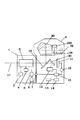
図1に、本実施形態におけるデジタル一眼レフカメラシステムの構成を示す。
図1において、1はレンズ本体、2は対物レンズとしての撮像光学系、3はレンズ駆動手段、4はレンズ状態検出手段、5はレンズ制御手段、6は記憶手段である。
7は接点、8はカメラ本体、11は撮像素子、12は焦点検出手段、13はカメラ制御手段、14は演算手段、15は記憶手段、16は焦点判定手段である。
17は光軸、19は主ミラ−、20はサブミラー、28は焦点板、29は接眼光学系、30は、ペンタプリズムであり、100は光源判別手段である。
Hereinafter, embodiments of the present invention will be described.
[Embodiment 1]
As
FIG. 1 shows a configuration of a digital single-lens reflex camera system in the present embodiment.
In FIG. 1, 1 is a lens body, 2 is an imaging optical system as an objective lens, 3 is lens driving means, 4 is lens state detection means, 5 is lens control means, and 6 is storage means.
7 is a contact point, 8 is a camera body, 11 is an image sensor, 12 is focus detection means, 13 is camera control means, 14 is calculation means, 15 is storage means, and 16 is focus determination means.
本実施形態の形態のカメラシステムは、レンズ本体1とカメラ本体8とで構成されている。
レンズ本体1内に収容された撮像光学系2は、1つ又は複数のレンズ群から構成され、その全てもしくは一部を移動させることで焦点距離やフォーカスを変化させることが可能とされている。
レンズ駆動手段3は、撮像光学系2の光軸17、撮像光学系2を構成するレンズの全てもしくは一部を移動させて焦点状態を調整する駆動手段である。
レンズ状態検出手段4は、撮像光学系2の焦点距離、即ちズーム状態およびフォーカス状態を検出する検出手段である。
ここで、このレンズ状態検出手段4に、公知の方法、例えば撮像光学系2の焦点距離を変化させる為に回転または移動する鏡筒に設けられたエンコーダ用の電極とそれに接する検出用の電極等を用いる。
これにより、前記撮像光学系2の焦点距離(ズーム状態)及びフォーカスを変化させる際に移動するレンズの移動状態、または移動状態を特徴付ける量を検出するように構成することができる。
また、レンズ制御手段5は、ROM等で構成された記憶手段6を含むレンズ本体1全体の制御を司るCPU等からなる制御手段である。
The camera system according to this embodiment includes a
The imaging
The lens driving unit 3 is a driving unit that adjusts the focus state by moving all or a part of the
The lens
Here, in this lens state detection means 4, a known method, for example, an electrode for an encoder provided on a lens barrel that rotates or moves in order to change the focal length of the imaging
Accordingly, it is possible to detect the moving state of the lens that moves when the focal length (zoom state) and focus of the imaging
The lens control means 5 is a control means composed of a CPU or the like that controls the
カメラ本体8内には、主ミラー19、物体像が形成されている焦点板28、像反転用のペンタプリズム30、接眼光学系29が設けられ、これらによってファインダー系が構成されている。
また、このカメラ本体8内には、前記主ミラー19を透過してきた光束を、焦点検出手段に導くサブミラー、前記撮像光学系2が形成する被写体像を撮影する為の撮像素子11、焦点検出手段12が設けられている。
また、このカメラ本体8内には、カメラ本体8全体の制御を司るCPU等からなるカメラ制御手段13が設けられている。
また、このカメラ本体8内には、撮像素子で撮影された画像のコントラスト検出を行い合焦位置を判定する焦点判定手段16、該焦点判定手段16からの出力と前記焦点検出手段12からの出力との差分による補正値を算出する演算手段14が設けられている。
さらに、このカメラ本体8内には、該演算手段により算出された差分量を補正情報として記憶する記憶手段15が設けられている。
なお、前記焦点判定手段16によるコントラストの検出には、従来例によるコントラスト方式の焦点検出手段を用いることができる。
また、光源判別手段100は、焦点板28に結像した被写体象を受光し赤外光の強弱などから光源の種類を判別する手段である。
接点7はレンズ本体1およびカメラ本体8に具備された接点であり、この接点により互いに装着された状態では該接点7を介して各種の情報の通信や電源の供給が行われる。
また、本実施の形態におけるカメラシステムは、前述した補正情報を算出し、記憶するためのキャリブレーションモードが設定可能に構成(不図示)されている。
In the
Further, in the
In the
Further, in the
Further, in the
For the contrast detection by the
The light source discriminating means 100 is a means for receiving a subject image formed on the focusing
The
In addition, the camera system according to the present embodiment is configured (not shown) so that a calibration mode for calculating and storing the correction information described above can be set.
つぎに、焦点検出手段12の主要部分の構成について、さらに説明する。
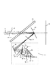
図2に、図1における焦点検出手段12の主要部分の構成を示す。
図2において、17は撮像光学系の光軸、18は図1の撮像素子11の置かれる撮影光学系2の結像面の位置を示している。
19は撮像光学系2の光軸17上に配置された半透過性の主ミラー、20は同様に撮像光学系2の光軸17上に斜めに配置された正のパワーを持つ第1の反射鏡、21は第1の反射鏡20により反射された像面18に共役な近軸的結像面である。
22は第2の反射鏡、23は赤外カットフィルタ、24はAF絞りであり、2つの開口24−1、24−2を有している。
25は2次結像系であり、AF絞り24の2つの開口24−1、24−2に対応して配置された2つのレンズ25−1、25−2を有している。
26は光電変換素子(センサ)であり、2つのエリアセンサ26−1、26−2を有している。また、36は第3の反射鏡である。
Next, the configuration of the main part of the focus detection means 12 will be further described.
FIG. 2 shows the configuration of the main part of the focus detection means 12 in FIG.
In FIG. 2, 17 indicates the optical axis of the imaging optical system, and 18 indicates the position of the imaging plane of the imaging
19 is a semi-transparent main mirror disposed on the
A photoelectric conversion element (sensor) 26 has two area sensors 26-1 and 26-2.
ここで、前記第1の反射鏡20は曲率を有し、AF絞り24の2つの開口24−1、24−2を撮影光学系2の射出瞳付近に投影する収束性のパワー(屈折力)を持っている。
また、前記第1の反射鏡20は、必要な領域のみが光を反射するようにアルミニウムや銀等の金属膜が蒸着されていて、焦点検出を行う範囲を制限する視野マスクの働きを兼ねている。
他の第2の反射鏡22、第3の反射鏡36においても、光電変換素子26上に入射する迷光を減少させるため、必要最低限の領域のみが蒸着されている。
なお、各反射鏡の反射面として機能しない領域には、光吸収性の塗料等を塗布することが好ましい。
Here, the first reflecting
Further, the first reflecting
In the other second reflecting
In addition, it is preferable to apply a light-absorbing paint or the like to a region that does not function as a reflecting surface of each reflecting mirror.
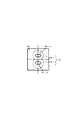
図3は、図2に示したAF絞り24の平面図である。
AF絞り24は、横長の2つの開口24−1、24−2を開口幅の狭い方向に並べた構成となっている。
図中、点線で示されているのは、AF絞り24の開口24−1、24−2に対応してその後方に配置されている2次結像系25の各光学系25−1、25−2である。
また、図4は、図2に示した光電変換素子26の平面図である。
図4で示した2つのエリアセンサ26−1,26−2は、この図に示すように2次元的に画素を配列したエリアセンサを2つ並べたものである。
FIG. 3 is a plan view of the
The
In the drawing, the dotted lines indicate the respective optical systems 25-1 and 25 of the
FIG. 4 is a plan view of the
The two area sensors 26-1 and 26-2 shown in FIG. 4 are obtained by arranging two area sensors in which pixels are two-dimensionally arranged as shown in FIG.
以上の構成要素を有する焦点検出系において、図2に示すように、撮像光学系2からの光束27−1、27−2は、主ミラー19のハーフミラー面を透過後、第1の反射鏡20によりほぼ主ミラー19の傾きに沿った方向に反射される。
第2の反射鏡22によって再び方向を変えられた後、赤外カットフィルタ23を介してAF絞り24の2つの開口24−1、24−2を経て、2次結像系25の各光学系25−1、25−2により集光される。
そして、第3の反射鏡36を介して光電変換素子26のエリアセンサ26−1、26−2上にそれぞれ到達する。
図2中の光束27−1、27−2は撮像面18に配置される不図示の撮像素子の中央に結像する光束を示したものではあるが、他の位置に結像する光束についても同様の経路を経て、光電変換素子26に達する。
そして、全体として、撮像素子上の所定の2次元領域に対応する被写体像に関する2つの光量の分布が光電変換素子26の各エリアセンサ26−1、26−2上に形成される。
In the focus detection system having the above components, as shown in FIG. 2, the light beams 27-1 and 27-2 from the imaging
After the direction is changed again by the second reflecting
And it reaches | attains on the area sensors 26-1 and 26-2 of the
The light beams 27-1 and 27-2 in FIG. 2 indicate the light beam that forms an image at the center of an image sensor (not shown) arranged on the
As a whole, a distribution of two light amounts relating to a subject image corresponding to a predetermined two-dimensional area on the image sensor is formed on each area sensor 26-1, 26-2 of the
図1における焦点検出手段12は、上記のようして得られた2つの被写体像に関する光量分布に対して、従来から用いられている位相差検出方式による焦点検出方法と同様の検出原理に基づき、撮像光学系2の焦点状態を検出する。
すなわち、被写体像の分離方向である図4に示す2つのエリアセンサ26−1、26−2の上下方向の相対的位置関係を、エリアセンサ26−1、26−2の各位置で算出することで撮像光学系2の焦点状態を検出し、その結果を焦点はずれ量Dとして出力する。
しかしながら、直接得られる焦点はずれ量に関する焦点状態検出信号に基づいてレンズの制御を行うと、適正な焦点状態を得られないことがある。
そのため、各レンズ本体1(撮像レンズ)毎に固有の補正値をレンズ側記憶手段6に記憶させ、これを用いて最良結像位置と撮像面を一致させるための補正が行れる。
しかしながら、このレンズ側記憶手段に記憶されている補正値は、各レンズの個体差及び前記焦点検出手段12の個体差を含んでいないため、適正な焦点検出状態を得られないという不都合を生じる。
The
In other words, the relative positional relationship in the vertical direction of the two area sensors 26-1 and 26-2 shown in FIG. 4 that is the separation direction of the subject image is calculated at each position of the area sensors 26-1 and 26-2. Then, the focus state of the imaging
However, if the lens is controlled based on the focus state detection signal regarding the amount of defocus directly obtained, an appropriate focus state may not be obtained.
For this reason, a correction value unique to each lens body 1 (imaging lens) is stored in the lens-side storage means 6, and correction for matching the best imaging position with the imaging surface can be performed using this.
However, since the correction value stored in the lens-side storage means does not include the individual difference of each lens and the individual difference of the focus detection means 12, there arises a disadvantage that an appropriate focus detection state cannot be obtained.
以上のことから、本実施の形態においては、前記補正値をより高精度な値とするため、つぎのような構成を採っている。
すなわち、前記レンズ駆動手段3によってレンズのフォーカス状態を変化させながら、前記撮像素子11から得られる画像信号のコントラストを検出し、該コントラストから前記焦点判定手段16により、合焦位置を判定する。
そして、前述した位相差検出方式による焦点検出手段12で検出した合焦位置との差分量を、前記演算手段14により算出し、記憶手段15に記憶する。
その際、本実施の形態においては、光源判別手段100によって光源の種別を判別して記憶手段15に同時に記憶するように構成されている。
これによって、撮影時に同じ光源の種類の補正値を用いることができ、より正確な補正が可能となる。
なお、以上の説明では、光源判別手段100によって光源の種別を判別して補正値としたが、本発明はこれに限られるものではない。
例えば、カメラに備えられた各種のセンサーにより環境情報たとえば温度、湿度などの情報を同時に記憶し、撮影時の環境情報に照らし合わせてより精度の高い補正を行うように構成することも可能である。
From the above, in the present embodiment, the following configuration is adopted in order to make the correction value a more accurate value.
That is, the contrast of the image signal obtained from the
Then, the difference from the in-focus position detected by the
At this time, in the present embodiment, the light
Thereby, the correction value of the same light source type can be used at the time of photographing, and more accurate correction can be performed.
In the above description, the light
For example, environmental information such as temperature and humidity can be stored simultaneously by various sensors provided in the camera, and correction can be made with higher accuracy in light of environmental information at the time of shooting. .
つぎに、本実施の形態における以上の内容をキャリブレーションモードとして組み入れたカメラシステムの動作について説明する。
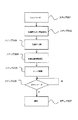
図5に、そのカメラシステムの動作を説明するフローチャートを示す。
まず、キャリブレーションモードが選択されると、自動的、もしくは撮影者のシャッタースイッチONによりキャリブレーションモードをスタートさせる(ステップ501)。
つぎに、前記レンズ駆動手段3によりレンズをデフォーカス(ステップ502)させる。
つぎに、レンズをデフォーカスさせた状態で前記撮像素子11から得られる画像信号のコントラストを前記焦点判定手段16にて検出する(ステップ503)。そして、ステップ502とステップ503を複数回繰り返した後、検出したコントラストのうち最もコントラストの高い画像信号が得られたデフォーカス位置から合焦位置を判定し合焦位置情報を作成する(ステップ504)。
Next, the operation of the camera system incorporating the above contents in the present embodiment as a calibration mode will be described.
FIG. 5 shows a flowchart for explaining the operation of the camera system.
First, when the calibration mode is selected, the calibration mode is started automatically or when the photographer turns on the shutter switch (step 501).
Next, the lens driving means 3 defocuses the lens (step 502).
Next, the focus determination means 16 detects the contrast of the image signal obtained from the
つぎに、前記焦点検出手段12を用いて位相差方式の焦点検出を行い、合焦位置情報を作成する(ステップ505)。
つぎに、光源判別手段100により光源の種別を判別する(ステップ506)。
その際、この光源判別は、例えば、可視域の光強度と赤外領域の光強度非から光源を推定する単純な方法でも良いし、あるいは分光強度分布を測定することにより光源の精密な特定を行う方法でも良い。
また、分光強度分布の情報そのものであっても特定光源下での補正値情報として有効な光源情報となる。
つぎに、前記焦点判定手段16にて判定した合焦位置情報と前記焦点検出手段12を用いて作成した合焦位置情報との差分を、前記演算手段14にて算出する(ステップ507)。
そして、この算出された合焦位置補正値を光源情報と共に前記記憶手段15に記憶させる(ステップ508)。
ここで、合焦カメラ動作時に判別される光源の種類によって記憶された補正値は、撮影時の光源と同種のものを用いる。
Next, phase difference type focus detection is performed using the focus detection means 12, and focus position information is created (step 505).
Next, the type of the light source is determined by the light source determination means 100 (step 506).
In this case, the light source discrimination may be, for example, a simple method of estimating the light source from the light intensity in the visible region and the light intensity in the infrared region, or by accurately measuring the light source by measuring the spectral intensity distribution. The method to do may be used.
Further, even the spectral intensity distribution information itself is effective light source information as correction value information under a specific light source.
Next, a difference between the focus position information determined by the focus determination means 16 and the focus position information created using the focus detection means 12 is calculated by the calculation means 14 (step 507).
Then, the calculated in-focus position correction value is stored in the
Here, the correction value stored according to the type of the light source discriminated during the operation of the focusing camera is the same type as the light source at the time of shooting.
以上の動作を経てキャリブレーションが終了する。
ここで、前記ステップ504とステップ505とステップ507の間にタイムラグがあると被写体の移動等により誤差が生じることも考えられることから、前記ステップ504とステップ505およびステップ507は同時に行われることがより望ましい。
また、上述したように一般的な被写体を用いてキャリブレーションを行おうとすると、被写体の移動等により誤差が生じることが考えられるため、特定のキャリブレーション用チャートを用いる方法が考えられる。
例えば、キャリブレーションチャートを壁などに固定し、キャリブレーションモードによって補正値の記憶を行う。
本実施の形態によれば、上記した光源判別手段を有することから、キャリブレーション実効者はキャリブレーションを行う際に、光源環境を気にすることなくキャリブレーションを行うことが可能となる。
勿論、特定のキャリブレーションチャートを用いない場合でも、本実施の形態によれば、キャリブレーション実効者は光源などを気にすることなくキャリブレーションの実行が可能である。
The calibration is completed through the above operations.
Here, if there is a time lag between step 504, step 505, and step 507, an error may occur due to movement of the subject. Therefore, step 504, step 505, and step 507 may be performed simultaneously. desirable.
Further, as described above, if calibration is performed using a general subject, an error may occur due to movement of the subject, and therefore, a method using a specific calibration chart can be considered.
For example, a calibration chart is fixed to a wall or the like, and correction values are stored in a calibration mode.
According to the present embodiment, since the above-described light source discriminating means is provided, the calibration effective person can perform calibration without worrying about the light source environment when performing calibration.
Of course, even if a specific calibration chart is not used, according to the present embodiment, the calibration effective person can execute the calibration without worrying about the light source or the like.
ここで、キャリブレーションを行う方法としては、パーソナルコンピュータ(以下、PCと記す)を用いる方法等によることができる。
その際、例えば、PCとの接続もしくはPC上でソフトウエアを実行することにより、PCの画面上にチャートを映し出し、該チャートを用いてキャリブレーションを行う方法を採ることができる。
これにより、使用するレンズの焦点距離や撮影距離により表示チャートを最適な大きさに自動的に設定することが可能となる。
また、PC画面は一般的にはブラウン管や液晶画面など赤外光をあまり含まない分光強度となっているため、外部要因により影響される環境としての光源を特定する形で補正値とあわせて記憶する本発明の方法はその補正精度を向上させることに有効となる。
本実施の形態によれば、カメラシステムとして補正値算出を行った光源を認識できるため、PC画面で補正を行っても、太陽光下における撮影時に必要な補正量の推定が容易となり正確なピント合わせが可能となる。
Here, as a method for performing calibration, a method using a personal computer (hereinafter referred to as PC) or the like can be used.
In this case, for example, a method of projecting a chart on the PC screen by connecting to the PC or executing software on the PC and performing calibration using the chart can be employed.
As a result, it is possible to automatically set the display chart to an optimum size according to the focal length and shooting distance of the lens to be used.
Since the PC screen generally has a spectral intensity that does not contain much infrared light, such as a cathode ray tube or a liquid crystal screen, it is stored together with correction values in a form that identifies the light source as an environment affected by external factors. The method of the present invention is effective in improving the correction accuracy.
According to this embodiment, since the light source for which the correction value has been calculated can be recognized as a camera system, even if correction is performed on the PC screen, it is easy to estimate the correction amount necessary for shooting under sunlight, and the correct focus Matching is possible.
また、前記焦点判定手段16によるコントラストの検出には、従来のビデオカメラに用いられているコントラスト方式の焦点検出手段を用いてもよい。
また、カメラ本体に機械的シャッターが備えられていたり、電子シャッターを行うことができない撮像素子が用いられていて、従来のコントラスト方式の焦点検出を行えない場合には、複数枚の画像を撮影し該画像のコントラスト検出するようにしてもよい。
また、前記合焦位置補正値の記憶は、レンズ内に設けられた前記記憶手段6内に記憶させた背景技術で説明した撮像レンズ毎に固有の補正値Cを書き換えるようにしても良い。
あるいは、前記補正値Cとは別の補正値として記憶するようにしてもも良い。
さらに、前記合焦補正値の記憶はカメラ本体に設けられた前記記憶手段15に前記合焦位置補正値のみを記憶しても良いし、前記補正値Cの値を含むような数値として記憶しても良い。
さらに、該キャリブレーションモードでは、上述したようなキャリブレーション動作を被写体距離毎に行い、各レンズを識別する識別情報毎に合焦位置補正値を求めることがより望ましい。
また、前記キャリブレーションの動作では前記焦点判定手段による合焦位置情報作成後、前記位相差方式の焦点検出を行っている。
しかし、前記焦点判定手段による合焦位置情報作成前に前記位相差方式の焦点検出を行い、前記ステップ502でレンズを駆動する範囲を前記位相差方式の焦点検出により検出された合焦位置付近に限定する。
これにより、より早くキャリブレーションを完了することが可能となる。
Further, for the contrast detection by the focus determination means 16, a contrast type focus detection means used in a conventional video camera may be used.
In addition, if the camera body is equipped with a mechanical shutter or an image sensor that cannot perform electronic shuttering is used and focus detection using the conventional contrast method cannot be performed, multiple images are taken. The contrast of the image may be detected.
The in-focus position correction value may be stored by rewriting the correction value C unique to each imaging lens described in the background art stored in the
Alternatively, it may be stored as a correction value different from the correction value C.
Further, the focus correction value may be stored in the storage means 15 provided in the camera body only as the focus position correction value or as a numerical value including the correction value C. May be.
Furthermore, in the calibration mode, it is more desirable to perform the calibration operation as described above for each subject distance, and obtain a focus position correction value for each identification information for identifying each lens.
In the calibration operation, the focus detection by the phase difference method is performed after the focus position information is generated by the focus determination unit.
However, the phase difference type focus detection is performed before the focus position information is created by the focus determination means, and the lens driving range in step 502 is close to the focus position detected by the phase difference type focus detection. limit.
As a result, calibration can be completed more quickly.
つぎに、キャリブレーションモードで作成した合焦位置補正値を用いて実際に撮影を行う場合のカメラの動作について説明する。
図6に、そのカメラの動作を説明するフローチャートを示す。
ここでは、合焦位置補正値は前記補正値Cとは別にカメラ内の前記記憶手段に記憶されている。
まず、レリーズボタンを半押しの状態(以後1stレリーズと呼ぶ)とする(ステップ601)。
これにより、前記焦点検出手段12により位相差方式で焦点検出が行われる(ステップ602)。
つぎに、光源判別手段100により光源を判別する(ステップ603)。
つぎに、この焦点検出手段12の焦点検出結果から、合焦位置情報を作成する(ステップ604)。
そして、この合焦位置情報に対し、前記各撮像レンズ毎に固有の補正値Cおよび前記キャリブレーションモードで作成した光源種類に応じた合焦位置補正値を用いて補正を行う(ステップ605)。
つぎに、これらの補正された合焦位置情報を元に前記レンズ駆動手段3によってレンズを駆動し、合焦動作を完了する(ステップ606)。
その後、前記レリーズボタンを押すことによって(以後2ndレリーズと呼ぶ)撮影が行われる(ステップ607)。
Next, the operation of the camera when actually taking a picture using the focus position correction value created in the calibration mode will be described.
FIG. 6 shows a flowchart for explaining the operation of the camera.
Here, the focus position correction value is stored in the storage means in the camera separately from the correction value C.
First, the release button is half-pressed (hereinafter referred to as 1st release) (step 601).
Thereby, the
Next, the light source is discriminated by the light source discriminating means 100 (step 603).
Next, focus position information is created from the focus detection result of the focus detection means 12 (step 604).
Then, the focus position information is corrected using a correction value C unique to each imaging lens and a focus position correction value corresponding to the type of light source created in the calibration mode (step 605).
Next, the lens is driven by the lens driving means 3 based on the corrected in-focus position information, and the in-focus operation is completed (step 606).
Thereafter, shooting is performed by pressing the release button (hereinafter referred to as 2nd release) (step 607).
以上のように、前記位相差方式で焦点検出を行う焦点検出手段12と前記焦点判定手段16とから得られる合焦位置の差分に加え、さらにキャリブレーションモードのもとでの光源判別手段100による光源の種別情報を記憶手段15に同時に記憶させる。
このようにして記憶された情報による補正値を撮影時に用いることで、位相差方式による高速性を維持しつつ、高精度の焦点検出が可能となる。
また、前述したように前記合焦位置補正値を前記補正値Cを含むような数値としてカメラ内の記憶手段に記憶しておけば、前記補正値Cをレンズ及びカメラ本体間で通信する必要がなく、さらに高速の焦点検出が可能となる。
As described above, in addition to the focus position difference obtained from the
By using the correction value based on the information stored in this way at the time of photographing, it is possible to detect the focus with high accuracy while maintaining the high speed by the phase difference method.
If the in-focus position correction value is stored as a numerical value including the correction value C in the storage means in the camera as described above, the correction value C needs to be communicated between the lens and the camera body. In addition, even faster focus detection is possible.
[実施形態2]
次に、本発明の実施形態2について説明する。
実施形態2では、キャリブレーションモードを用いず自動的に合焦位置補正値を算出するようにした点が実施形態1と相違するだけで、それ以外は実施形態1と同様である。
図7に、そのカメラシステムの動作を説明するフローチャートを示す。
まず、合焦位置補正値の算出を開始する(ステップ701)。
つぎに、前記焦点検出手段12を用い、位相差方式で焦点検出を行い、合焦位置情報を作成する(ステップ702)。
つぎに、該合焦位置情報を元に前記レンズ駆動手段3によりレンズを駆動し、合焦動作を行う(ステップ703)。
つぎに、前記レンズ駆動手段3により駆動されたレンズ位置より微小量レンズをデフォーカスさせる(ステップ704)。
つぎに、このデフォーカスされた状態での撮像素子からの画像信号のコントラストを前記焦点判定手段16にて検出する(ステップ705)。
そして、ステップ704とステップ705を複数回繰り返した後、検出したコントラストのうち最もコントラストの高い画像信号が得られたデフォーカス位置から合焦位置情報を作成する(ステップ706)。
つぎに、光源判別手段100により光源を判別する(ステップ707)。
つぎに、焦点判定手段16にて検出した合焦位置情報と前記焦点検出手段12を用いて作成した合焦位置情報との差分を前記演算手段14により算出する(ステップ708)。
このようにして算出された合焦位置補正値を、前記判別された光源の種類と共に前記記憶手段15に記憶させる(ステップ709)。以上のような動作によりキャリブレーションモードを用いず自動的に合焦位置補正値を算出する動作が終了する。
[Embodiment 2]
Next,
The second embodiment is the same as the first embodiment except that the in-focus position correction value is automatically calculated without using the calibration mode.
FIG. 7 shows a flowchart for explaining the operation of the camera system.
First, calculation of a focus position correction value is started (step 701).
Next, using the focus detection means 12, focus detection is performed by a phase difference method, and focus position information is created (step 702).
Next, the lens is driven by the lens driving means 3 based on the in-focus position information, and an in-focus operation is performed (step 703).
Next, the minute lens is defocused from the lens position driven by the lens driving means 3 (step 704).
Next, the focus determination means 16 detects the contrast of the image signal from the image sensor in the defocused state (step 705).
Then, after repeating step 704 and step 705 a plurality of times, focus position information is created from the defocus position from which the image signal with the highest contrast among the detected contrasts was obtained (step 706).
Next, the light source is discriminated by the light source discriminating means 100 (step 707).
Next, the difference between the focus position information detected by the focus determination means 16 and the focus position information created using the focus detection means 12 is calculated by the calculation means 14 (step 708).
The in-focus position correction value calculated in this way is stored in the
ここで、前記合焦位置補正値の算出を開始するタイミングについては、撮影者がレリーズボタンに触れていない状況で行う。
その際、撮影者の1stレリーズにより補正値算出を中断するといった方法を用いることができる。
また、実際の撮影時に設定されたシャッタースピードの1/2以下のシャッタースピードでデフォーカスさせながら複数回撮影動作を行う。
そして、撮影終了後画像処理により設定されたシャッタースピードでの撮影と同等の画像が得られるようにする方法を用いても良い。
該キャリブレーションで作成した合焦位置情報差分量を用いて実際に撮影を行う際の撮影動作は、実施態様1と同様の方法で行えばよい。
ここで、上述した焦点検出はレンズが交換される毎に行われることが望ましい。そのため、レンズが交換され該レンズの焦点検出及び露出の補正値が前記記憶手段に記憶されていない場合には、撮影者に補正値が記憶されていないことを警告することが望ましい。
また、前記焦点検出補正値は、本実施形態ではカメラ内に設けられた記憶手段に記憶されるが、前記レンズ内に設けられている記憶手段に記憶されている従来の補正値を書き換えるようにしてもよい。
Here, the timing for starting the calculation of the in-focus position correction value is performed when the photographer is not touching the release button.
At that time, a method of interrupting correction value calculation by the photographer's first release can be used.
Further, the photographing operation is performed a plurality of times while defocusing at a shutter speed less than 1/2 of the shutter speed set at the time of actual photographing.
A method of obtaining an image equivalent to shooting at the shutter speed set by the image processing after shooting is completed may be used.
The photographing operation when actually photographing using the in-focus position information difference amount created by the calibration may be performed by the same method as in the first embodiment.
Here, it is desirable that the focus detection described above is performed every time the lens is replaced. Therefore, when the lens is replaced and the focus detection and exposure correction values of the lens are not stored in the storage unit, it is desirable to warn the photographer that the correction value is not stored.
Further, in the present embodiment, the focus detection correction value is stored in a storage unit provided in the camera, but the conventional correction value stored in the storage unit provided in the lens is rewritten. May be.
1:レンズ本体
2:撮像光学系
3:レンズ駆動手段
4:レンズ状態検出手段
5:レンズ制御手段
6:記憶手段
7:接点
8:カメラ本体
11:撮像素子
12:焦点検出手段
13:カメラ制御手段
14:演算手段
15:記憶手段
16:焦点判定手段
17:光軸
18:像面
19:主ミラ−
20:サブミラー
21:近軸像面
23:赤外カットフィルタ
24:AF絞り
28:焦点板
29:接眼光学系
30:ペンタプリズム
100:光源判別手段
1: Lens body 2: Imaging optical system 3: Lens drive means 4: Lens state detection means 5: Lens control means 6: Storage means 7: Contact point 8: Camera body 11: Image sensor 12: Focus detection means 13: Camera control means 14: Calculation means 15: Storage means 16: Focus determination means 17: Optical axis 18: Image plane 19: Main mirror
20: Sub mirror 21: Paraxial image plane 23: Infrared cut filter 24: AF stop 28: Focus plate 29: Eyepiece optical system 30: Penta prism 100: Light source discriminating means
Claims (9)
前記撮像素子からの出力信号に基づいてコントラスト検出方式により前記撮像光学系の合焦位置の判定を行う焦点判定手段と、
前記撮像光学系からの光束を用い、位相差検出方式により該撮像光学系の焦点検出を行う焦点検出手段と、を有するカメラにおいて、
前記焦点判定手段からの結果と前記焦点検出手段の検出結果に基づき、前記焦点検出手段で検出される合焦位置に対する検出誤差を補正する補正値を演算する補正値演算手段と、
撮影時の外的要因に起因する環境状況を判定する環境状況判定手段と、
前記補正値演算手段によって演算された補正値と、前記環境状況判定手段によって判定された環境状況による情報とを関連づけて記憶する記憶手段と、
を有し、前記記憶手段に記憶された補正値及び環境状況による情報に基づいて前記焦点検出手段における検出誤差を補正することを特徴とするカメラ。 An image sensor for imaging an image formed by the imaging optical system;
Focus determining means for determining the in-focus position of the imaging optical system by a contrast detection method based on an output signal from the imaging element;
In a camera having a focus detection unit that detects a focus of the imaging optical system by a phase difference detection method using a light beam from the imaging optical system,
Correction value calculation means for calculating a correction value for correcting a detection error for the in-focus position detected by the focus detection means based on the result from the focus determination means and the detection result of the focus detection means;
Environmental status determination means for determining environmental status caused by external factors at the time of shooting;
Storage means for storing the correction value calculated by the correction value calculation means and information on the environmental situation determined by the environmental situation determination means in association with each other;
And a detection error in the focus detection unit is corrected based on a correction value stored in the storage unit and information on an environmental condition.
Priority Applications (1)
| Application Number | Priority Date | Filing Date | Title |
|---|---|---|---|
| JP2005354662A JP2007156304A (en) | 2005-12-08 | 2005-12-08 | Camera, camera system, and interchangeable lens device |
Applications Claiming Priority (1)
| Application Number | Priority Date | Filing Date | Title |
|---|---|---|---|
| JP2005354662A JP2007156304A (en) | 2005-12-08 | 2005-12-08 | Camera, camera system, and interchangeable lens device |
Publications (2)
| Publication Number | Publication Date |
|---|---|
| JP2007156304A true JP2007156304A (en) | 2007-06-21 |
| JP2007156304A5 JP2007156304A5 (en) | 2009-01-29 |
Family
ID=38240728
Family Applications (1)
| Application Number | Title | Priority Date | Filing Date |
|---|---|---|---|
| JP2005354662A Pending JP2007156304A (en) | 2005-12-08 | 2005-12-08 | Camera, camera system, and interchangeable lens device |
Country Status (1)
| Country | Link |
|---|---|
| JP (1) | JP2007156304A (en) |
Cited By (4)
| Publication number | Priority date | Publication date | Assignee | Title |
|---|---|---|---|---|
| JP2009210872A (en) * | 2008-03-05 | 2009-09-17 | Canon Inc | Imaging device |
| JP2010137446A (en) * | 2008-12-12 | 2010-06-24 | Konica Minolta Business Technologies Inc | Image forming apparatus |
| JP2012123404A (en) * | 2007-08-13 | 2012-06-28 | Panasonic Corp | Imaging apparatus |
| JP2012203305A (en) * | 2011-03-28 | 2012-10-22 | Canon Inc | Imaging apparatus |
Citations (5)
| Publication number | Priority date | Publication date | Assignee | Title |
|---|---|---|---|---|
| JPH1026725A (en) * | 1996-05-10 | 1998-01-27 | Nikon Corp | Automatic focusing device |
| JP2003295047A (en) * | 2002-04-05 | 2003-10-15 | Canon Inc | Image pickup device and image pickup system |
| JP2004347665A (en) * | 2003-05-20 | 2004-12-09 | Canon Inc | Automatic focusing device |
| JP2005017673A (en) * | 2003-06-26 | 2005-01-20 | Fuji Photo Film Co Ltd | Method for searching for focusing position of focus lens, and imaging apparatus |
| JP2005352043A (en) * | 2004-06-09 | 2005-12-22 | Fuji Photo Film Co Ltd | Image pickup apparatus and focusing control method |
-
2005
- 2005-12-08 JP JP2005354662A patent/JP2007156304A/en active Pending
Patent Citations (5)
| Publication number | Priority date | Publication date | Assignee | Title |
|---|---|---|---|---|
| JPH1026725A (en) * | 1996-05-10 | 1998-01-27 | Nikon Corp | Automatic focusing device |
| JP2003295047A (en) * | 2002-04-05 | 2003-10-15 | Canon Inc | Image pickup device and image pickup system |
| JP2004347665A (en) * | 2003-05-20 | 2004-12-09 | Canon Inc | Automatic focusing device |
| JP2005017673A (en) * | 2003-06-26 | 2005-01-20 | Fuji Photo Film Co Ltd | Method for searching for focusing position of focus lens, and imaging apparatus |
| JP2005352043A (en) * | 2004-06-09 | 2005-12-22 | Fuji Photo Film Co Ltd | Image pickup apparatus and focusing control method |
Cited By (4)
| Publication number | Priority date | Publication date | Assignee | Title |
|---|---|---|---|---|
| JP2012123404A (en) * | 2007-08-13 | 2012-06-28 | Panasonic Corp | Imaging apparatus |
| JP2009210872A (en) * | 2008-03-05 | 2009-09-17 | Canon Inc | Imaging device |
| JP2010137446A (en) * | 2008-12-12 | 2010-06-24 | Konica Minolta Business Technologies Inc | Image forming apparatus |
| JP2012203305A (en) * | 2011-03-28 | 2012-10-22 | Canon Inc | Imaging apparatus |
Similar Documents
| Publication | Publication Date | Title |
|---|---|---|
| EP1351086B1 (en) | Image pickup apparatus with a focus adjusting device and an exposure system | |
| US7940323B2 (en) | Image-pickup apparatus and control method thereof | |
| JP2007233032A (en) | Focusing device and imaging apparatus | |
| JP5241096B2 (en) | IMAGING DEVICE, ITS CONTROL METHOD, PROGRAM, AND STORAGE MEDIUM | |
| JP5641771B2 (en) | Focus detection device | |
| JP5320855B2 (en) | Lens barrel and camera system | |
| JP2006254413A (en) | Imaging apparatus and camera body | |
| JP4560420B2 (en) | Imaging device | |
| JP2007156304A (en) | Camera, camera system, and interchangeable lens device | |
| JP2006065080A (en) | Imaging device | |
| JP2006084545A (en) | Camera, photographing lens, and camera system | |
| JP2007233033A (en) | Focusing device and imaging apparatus | |
| JP2004109864A (en) | Imaging apparatus and imaging system provided with it | |
| JP2005308960A (en) | Imaging apparatus provided with automatic focusing device | |
| JP5170266B2 (en) | Imaging device and camera body | |
| JP4865275B2 (en) | Focus detection apparatus and imaging apparatus | |
| JP4938922B2 (en) | Camera system | |
| JP5335615B2 (en) | Focus adjustment apparatus and control method thereof | |
| JP5590850B2 (en) | Imaging device and focus control method of imaging device | |
| JP4862297B2 (en) | Electronic camera and camera system | |
| JP4525023B2 (en) | Focus detection apparatus and imaging apparatus | |
| JP4928236B2 (en) | Imaging apparatus and imaging system | |
| JP4541808B2 (en) | Imaging apparatus and imaging system | |
| JP2007240566A (en) | Focus detecting device, optical apparatus and camera | |
| JP4946311B2 (en) | Focus adjustment device, camera |
Legal Events
| Date | Code | Title | Description |
|---|---|---|---|
| A521 | Written amendment |
Free format text: JAPANESE INTERMEDIATE CODE: A523 Effective date: 20081208 |
|
| A621 | Written request for application examination |
Free format text: JAPANESE INTERMEDIATE CODE: A621 Effective date: 20081208 |
|
| A977 | Report on retrieval |
Effective date: 20110118 Free format text: JAPANESE INTERMEDIATE CODE: A971007 |
|
| A131 | Notification of reasons for refusal |
Free format text: JAPANESE INTERMEDIATE CODE: A131 Effective date: 20110209 |
|
| A521 | Written amendment |
Free format text: JAPANESE INTERMEDIATE CODE: A523 Effective date: 20110407 |
|
| A02 | Decision of refusal |
Free format text: JAPANESE INTERMEDIATE CODE: A02 Effective date: 20110531 |