JP2004322084A - Biological filtration system - Google Patents
Biological filtration system Download PDFInfo
- Publication number
- JP2004322084A JP2004322084A JP2004111704A JP2004111704A JP2004322084A JP 2004322084 A JP2004322084 A JP 2004322084A JP 2004111704 A JP2004111704 A JP 2004111704A JP 2004111704 A JP2004111704 A JP 2004111704A JP 2004322084 A JP2004322084 A JP 2004322084A
- Authority
- JP
- Japan
- Prior art keywords
- chamber
- water
- contact
- aeration
- anaerobic
- Prior art date
- Legal status (The legal status is an assumption and is not a legal conclusion. Google has not performed a legal analysis and makes no representation as to the accuracy of the status listed.)
- Granted
Links
Images


Classifications
-
- Y—GENERAL TAGGING OF NEW TECHNOLOGICAL DEVELOPMENTS; GENERAL TAGGING OF CROSS-SECTIONAL TECHNOLOGIES SPANNING OVER SEVERAL SECTIONS OF THE IPC; TECHNICAL SUBJECTS COVERED BY FORMER USPC CROSS-REFERENCE ART COLLECTIONS [XRACs] AND DIGESTS
- Y02—TECHNOLOGIES OR APPLICATIONS FOR MITIGATION OR ADAPTATION AGAINST CLIMATE CHANGE
- Y02W—CLIMATE CHANGE MITIGATION TECHNOLOGIES RELATED TO WASTEWATER TREATMENT OR WASTE MANAGEMENT
- Y02W10/00—Technologies for wastewater treatment
- Y02W10/10—Biological treatment of water, waste water, or sewage
Abstract
Description
本発明は、各種廃水または下水等の生物学的処理装置に関する。 The present invention relates to a biological treatment device for various kinds of wastewater or sewage.
汚水排水を微生物により処理する方法として生物濾過方法がある。
これは生物濾過槽中に微生物を担持する接触濾材を設置し、処理水が担体の間隙を通過するときにその担体に付着させた微生物によって有機物の生分解を行い、さらに処理水中に浮遊している固形分を捕捉する方法である。
この方法は従来の沈殿槽による固形分の沈殿除去に比べ、固形分の除去能力が高く高度に処理出来る方法として知られている。
There is a biological filtration method as a method of treating sewage wastewater with microorganisms.
In this method, a contact filter medium that supports microorganisms is installed in a biological filtration tank, and when treated water passes through the gap between carriers, biodegradation of organic matter is performed by microorganisms attached to the carrier, and the microorganisms are further suspended in treated water. This is a method of capturing solids that are present.
This method is known as a method having a high solids removal capability and capable of performing a high degree of treatment as compared with a conventional method for removing solids by a sedimentation tank.
上記方法は、大きく3種類の処理方法に分類される。
まず、一つ目は充填する微生物担体が多孔質セラミックスのように、比重が水の比重に比べて大きい沈降性担体を使用し生物濾過槽内に沈降させ、その担体充填部分の下方より空気を散気しながら処理水を通過させ、担体表面に付着した微生物により有機物を分解し、さらに固形分を物理的に捕捉する方法である。
二つ目の方法は、繊維製接触剤を微生物担体として使用し、生物濾過槽内に該繊維製担体を複数固定して、その担体固定部分の下方より空気を散気しながら処理水を通過させ、浮遊する繊維担体に付着した微生物により有機物を分解する方法である。
三つ目の方法は、充填する粒状担体が合成樹脂の発泡体のように比重が水の比重に比較的近い浮上性担体を生物濾過槽に充填し下方より空気を散気させ、粒状担体を浮上または流動させながら、担体表面に付着した微生物により有機物を分解する方法である。
The above methods are roughly classified into three types of processing methods.
First, the microbial carrier to be filled is settled in the biological filtration tank using a sedimentable carrier whose specific gravity is larger than the specific gravity of water, such as porous ceramics, and air is blown from below the carrier-filled part. This is a method in which treated water is passed while diffusing, organic substances are decomposed by microorganisms attached to the surface of the carrier, and solids are physically captured.
The second method uses a fiber contact agent as a microorganism carrier, fixes a plurality of the fiber carriers in a biological filtration tank, and passes the treated water while diffusing air from below the carrier fixing part. In this method, organic substances are decomposed by microorganisms attached to the floating fiber carrier.
The third method is to fill the biological filtration tank with a floating carrier whose specific gravity is relatively close to the specific gravity of water, such as a synthetic resin foam, and to diffuse air from below, thereby removing the granular carrier. This is a method in which organic substances are decomposed by microorganisms attached to the surface of a carrier while floating or flowing.
浮遊する繊維担体や浮上性担体を使用した場合、処理水中に浮遊している固形物の捕捉能力は小さく、さらに担体表面に付着した微生物が担体同士の摩擦や水流によって剥離し、浮遊性固形物として放流され処理水のBODが増加することになるが、このような問題に対して、特開平5−309382号公報には、生物濾過槽を2つに区分し、担体を流動させて有機物の分解を主目的とする部分と担体を静止させて固形物を捕捉する部分に機能分離させる方法が記載されており、また特開2002−361275号公報には処理水中の浮遊性固形分を、微生物を貯蔵する処理槽内で分解させた後、透水性を有する濾過材に透過させることにより分解処理する方法が記載されているが、多量の余剰汚泥の発生は避けられず、汚泥処理の手間と費用負担が問題となっている。 When a floating fiber carrier or a floating carrier is used, the ability to capture solids suspended in the treated water is small, and microorganisms attached to the carrier surface are separated by friction between carriers and water flow, and the floating solids are removed. In order to deal with such a problem, Japanese Patent Application Laid-Open No. Hei 5-309382 discloses that a biological filtration tank is divided into two parts, and a carrier is fluidized to remove organic matter. A method is described in which a part mainly intended for decomposition is separated from a part for capturing a solid by stopping a carrier, and Japanese Patent Application Laid-Open No. 2002-361275 discloses a method for separating floating solids in treated water from microorganisms. After decomposing in a treatment tank that stores the water, a method of decomposing by passing through a water-permeable filter medium is described, but the generation of a large amount of excess sludge is inevitable, and the time and effort of sludge treatment are reduced. Expense The burden has become a problem.
さらに、繊維担体に炭素繊維を用いることで、汚泥の活性が長時間持続するため余剰汚泥の発生が少なく、固着汚泥の剥離がおきにくく、SS捕捉効率が高くなるという特性(大谷杉郎、炭素TANSO 2000[No.194]PP.276〜287)を利用して、特開平11−99399号公報には、炭素繊維からなる接触材を用いた排水処理装置が記載されているが、ブロアを用いた散気装置では消費エネルギーが大きい割には接触濾材への溶存酸素供給能力が小さいこと、接触濾過室内で水流の偏りが発生して水流の揺らぎによるせん断力で炭素繊維が切れて損耗したり、生物膜の剥離が発生しやすくなり、装置内に余剰汚泥が堆積するという問題があった。 In addition, the use of carbon fiber as the fiber carrier has the characteristic that sludge activity is maintained for a long time, so that excess sludge is less generated, sticking sludge is less likely to occur, and the SS trapping efficiency is increased (Suguro Otani, U.S. Patent Application Publication No. US 2003/0128399 A1 discloses a wastewater treatment apparatus using a contact material made of carbon fiber using TANSO 2000 [No. 194] PP.276 to 287). In the air diffuser, the energy consumption is large but the ability to supply dissolved oxygen to the contact filter medium is small, and the water flow is biased in the contact filtration chamber, and the carbon fibers are cut and worn due to the shear force caused by the fluctuation of the water flow. In addition, there is a problem that separation of the biofilm is apt to occur, and excess sludge accumulates in the apparatus.
加えて、微細気泡発生装置を用いて処理水中へ効率的に溶存酸素を供給する方法は、特許第2646442号公報、特開平5−64795号公報、特開平7−265057号公報、特開2000−618002号公報、特開2000−447号公報、特開2001−58142号公報、特開2002−370095号公報に記載されているが、微細気泡製造時に吐出噴流を用いて曝気撹拌する方式であり、曝気装置としてこのまま生物濾過槽に使用しても接触濾過室の流向を安定化させることは困難であること、また微細気泡の特性として吸着凝集効果を持つため、余剰汚泥や処理水中に浮遊している固形物を吸着浮上させ接触濾過室から積極的に流出させてしまうという問題があった。 In addition, a method for efficiently supplying dissolved oxygen to treated water using a microbubble generator is disclosed in Japanese Patent No. 2646442, Japanese Patent Application Laid-Open No. 5-64795, Japanese Patent Application Laid-Open No. 7-265057, and Japanese Patent Application Laid-Open No. 2000-2000. No. 618002, JP-A-2000-4747, JP-A-2001-58142, and JP-A-2002-370095 are systems in which aeration and agitation are performed using a discharge jet at the time of producing fine bubbles, It is difficult to stabilize the flow direction of the contact filtration chamber even if it is used as it is in a biological filtration tank as it is, and because it has an adsorption and coagulation effect as a characteristic of fine bubbles, it can be suspended in excess sludge or treated water. There is a problem in that the solid matter that is present is adsorbed and floated and is positively discharged from the contact filtration chamber.
また、余剰汚泥の低減をねらいに嫌気性微生物処理と好気性微生物処理を組み合わせることも検討されている。例えば、特開2003−136087号公報には、好気性微生物に害のある成分の分解及び曝気エネルギーの低減を目的に上部に好気部を形成し、下部に嫌気部を形成した例を開示する。
しかし、処理水を好気部と嫌気部の間を上下に循環させるもので、例えば、BOD1,000mg/L以下の比較的低濃度の排水を連続的に処理するには不適である。
Also, a combination of anaerobic microorganism treatment and aerobic microorganism treatment is being studied with the aim of reducing excess sludge. For example, Japanese Patent Application Laid-Open No. 2003-136087 discloses an example in which an aerobic portion is formed at an upper portion and an anaerobic portion is formed at a lower portion for the purpose of decomposing components harmful to aerobic microorganisms and reducing aeration energy. .
However, since the treated water is circulated up and down between the aerobic part and the anaerobic part, it is not suitable for continuously treating relatively low-concentration wastewater having a BOD of 1,000 mg / L or less, for example.
本発明は、接触濾過室内の流向の安定性に優れ、接触濾材の損耗や生物膜の剥離を防ぎ、さらには、嫌気性微生物処理から好気性微生物処理へと連続的に安定して処理できる生物濾過装置の提供を目的とする。 The present invention has excellent flow direction stability in a contact filtration chamber, prevents wear of a contact filter medium and detachment of a biofilm, and furthermore, a biological substance that can be continuously and stably treated from an anaerobic microorganism treatment to an aerobic microorganism treatment. It is intended to provide a filtration device.
本発明に係る生物濾過装置の技術的要旨は、上部の接触濾過室と下部の曝気室とを透過性を有する隔壁で上下に分離し、接触濾過室には処理水の放流口を備え、曝気室内には水平方向の旋回流が生じるように原水又は処理循環水を注入する注水口と、溶存酸素供給手段とを備えた点にある。 The technical gist of the biological filtration device according to the present invention is that an upper contact filtration chamber and a lower aeration chamber are vertically separated by a partition having permeability, and the contact filtration chamber is provided with an outlet for treated water. The room is provided with a water inlet for injecting raw water or treated circulating water so as to generate a horizontal swirling flow, and a dissolved oxygen supply means.
ここで、接触濾過室とは、微生物を担体に付着させた接触濾材を配置した室をいい、曝気室とは、溶存酸素を添加する室を言う。
曝気室内に水平方向の旋回流が生じるように原水又は処理循環水を注入する注水口を備えるとは、例えば、処理循環水の吐出口を曝気室の内壁に斜め方向に設けて注水することでその水流にて概ね水平方向の旋回流を発生させることを趣旨とする。
従って、注水口の備え方は曝気室の形状により異なり、円筒形状であれば、そのまま接線方向に吐出すればよく、方形形状であれば、円弧状の水流板を取り付けることも有効である。
本発明にては、曝気室内に原水又は処理循環水を注入することで、水平方向の旋回流が生じると、旋回流の中心部の圧力が周囲より低くなり、緩やかな鉛直方向の対流が発生する。
その際に、上部の接触濾過室と下部の曝気室とを透過性を有する隔壁で上下に分離したので、曝気室と接触濾過室との間の処理水移動を隔壁が抑制し、接触濾過室の水平方向の旋回流を緩やかにして安定した水流になると共に、鉛直方向の緩やかな対流により、下部の曝気室から上部の接触濾過室に供給され、放流口から処理された水が放流することになる。
ここで、曝気室に注入される水は、循環処理水と共に排水原水が供給されるが、原水を直接的に曝気室に注水管等を接続して注水する方法のみならず、接触濾過室の上部から原水を投入し中心部に発生する下向きの対流により間接的に曝気室内に注入する方法でも良い。
Here, the contact filtration chamber refers to a chamber in which a contact filter medium having microorganisms adhered to a carrier is disposed, and the aeration chamber refers to a chamber to which dissolved oxygen is added.
Providing a water injection port for injecting raw water or processing circulating water so that a horizontal swirling flow occurs in the aeration chamber means, for example, that a discharge port for processing circulating water is provided obliquely on the inner wall of the aeration chamber and water is injected. The purpose is to generate a substantially horizontal swirling flow in the water flow.
Therefore, the way of providing the water inlet differs depending on the shape of the aeration chamber. If it is a cylindrical shape, it may be discharged in the tangential direction as it is, and if it is a square shape, it is effective to attach an arc-shaped water flow plate.
In the present invention, by injecting raw water or treated circulating water into the aeration chamber, when a horizontal swirling flow occurs, the pressure at the center of the swirling flow becomes lower than the surroundings, and gentle vertical convection occurs. I do.
At that time, the upper contact filtration chamber and the lower aeration chamber were separated vertically by a partition having permeability, so that the partition suppressed the movement of treated water between the aeration chamber and the contact filtration chamber, and the contact filtration chamber Smooth the horizontal swirling flow of the water to make it a stable water flow, and by gentle convection in the vertical direction, the water is supplied from the lower aeration chamber to the upper contact filtration chamber, and the treated water is discharged from the discharge port. become.
Here, as for the water injected into the aeration chamber, raw waste water is supplied together with the circulating treated water. Not only a method of directly connecting the raw water by connecting a water injection pipe or the like to the aeration chamber, but also a method of supplying water to the contact filtration chamber. It is also possible to use a method in which raw water is supplied from above and indirectly injected into the aeration chamber by downward convection generated in the center.
本発明にて、溶存酸素供給手段とは、処理水中に溶存酸素を供給できる手段をいい、接触濾過室に配設した好気性微生物に充分な酸素を供給するのが目的である。
従って、処理水を撹拌する必要はなく、微細気泡発生装置は酸素溶解効率が高く好ましい。
また、接触濾過室内に配設する接触濾材(微生物担体)は特に限定されないが、本発明にては、接触濾過室の水流が緩やかな、水平方向の旋回流と垂直方向の対流になるので繊維フィラメント、モール状繊維ひもでもよく、これらの繊維が炭素繊維であってもよい。
In the present invention, the dissolved oxygen supply means refers to a means capable of supplying dissolved oxygen to treated water, and has an object of supplying sufficient oxygen to aerobic microorganisms disposed in a contact filtration chamber.
Therefore, it is not necessary to agitate the treated water, and a fine bubble generator is preferable because of its high oxygen dissolving efficiency.
Further, the contact filter medium (microorganism carrier) provided in the contact filtration chamber is not particularly limited. However, in the present invention, since the water flow in the contact filtration chamber is gentle, a horizontal swirling flow and a vertical convection, the It may be a filament or a stranded fiber string, and these fibers may be carbon fibers.
第二の技術的要旨は、上部の接触濾過室と下部の曝気室とを透過性を有する隔壁で上下に分離し、接触濾過室には処理水の放流口を備え、曝気室内には水平方向の旋回流が生じるように処理循環水を注入する注水口と、溶存酸素供給手段とを備え、曝気室の下に、さらに嫌気濾床室を備え、曝気室と嫌気濾床室との間を透過性を有する隔壁で分離し、嫌気濾床室内に原水を注入する注入口を備えた点にある。 The second technical gist is that the upper contact filtration chamber and the lower aeration chamber are vertically separated by a permeable partition wall, the contact filtration chamber is provided with an outlet for treated water, and the aeration chamber has a horizontal direction. A water inlet for injecting the treatment circulating water so as to generate a swirling flow, and a dissolved oxygen supply means, further provided with an anaerobic filter bed chamber below the aeration chamber, and provided between the aeration chamber and the anaerobic filter bed chamber. It is characterized in that it is separated by a partition having permeability and has an inlet for injecting raw water into the anaerobic filter bed chamber.
ここで、嫌気濾床室とは嫌気性微生物を付着させた担体を配置した室を言う。
嫌気濾床室に原水を注入すると、嫌気濾床室の上部に位置する曝気室に水平方向の旋回流が生じているので、原水は微生物担体の隙間を通過するように引き込まれる。
なお、有機物が、嫌気部(嫌気性微生物)にて分解する際に硫化水素が発生するが、その上部の好気部で酸化されて硫酸に戻るので装置から硫化水素ガスが発生することはない。
曝気室に引き込まれた処理水は、溶存酸素が添加され、曝気室と接触濾過室とで、先に述べた水平方向の旋回流と、緩やかな垂直方向の対流にて生物濾過される。
Here, the anaerobic filter bed chamber refers to a chamber in which a carrier to which anaerobic microorganisms are attached is arranged.
When raw water is injected into the anaerobic filter bed chamber, a horizontal swirling flow is generated in the aeration chamber located above the anaerobic filter bed chamber, so that the raw water is drawn in so as to pass through the gap between the microorganism carriers.
Hydrogen sulfide is generated when the organic matter is decomposed in the anaerobic part (anaerobic microorganism), but hydrogen sulfide gas is not generated from the apparatus because it is oxidized in the upper aerobic part and returns to sulfuric acid. .
Dissolved oxygen is added to the treated water drawn into the aeration chamber, and biological filtration is performed between the aeration chamber and the contact filtration chamber by the above-described horizontal swirling flow and gentle vertical convection.
本発明の生物濾過装置においては、接触濾過室の流れを緩やかに旋回、対流させることで接触濾過速度が安定化し、微細気泡発生装置を用いると、高濃度の溶存酸素を効率よく供給しつつも処理水中に浮遊している固形物の捕捉能力は高く、余剰汚泥の凝集浮上による流出が無く、生物濾過膜の剥離や接触濾材である繊維フィラメントの切断を防止すると共に、曝気室の旋回流で余剰汚泥の堆積を防止することができる。
また、接触濾材に炭素繊維フィラメントを用いた場合には、微生物親和性が高く汚泥が強固に付着し、汚泥の剥離は極めて少なくなる。
さらに、詳細に説明すると、曝気室内の処理水を循環水流により旋回させると同時に、接触濾過室と曝気室との通水量を透過性の隔壁で抑制することで、接触濾過室内に設置した接触濾材に接触する旋回流速を緩やかにして安定化させ、生物膜の剥離や繊維フィラメントの損耗を防ぎつつ超微細気泡による浮遊物質の吸着浮上を接触濾材で水平方向に濾過し、且つ、生物濾過装置内に鉛直方向の対流を発生させることで曝気室内の溶存酸素を含む処理水を接触濾過室へ緩やかに供給し、さらに余剰汚泥を曝気室内の旋回流で底部中央に集め、処理水の引抜き循環時に吸引し、微細気泡発生装置内で粉砕したのちに接触濾過処理することで余剰汚泥の堆積を低減できる。
In the biological filtration device of the present invention, the contact filtration speed is stabilized by gently swirling and convection in the flow of the contact filtration chamber, and the use of a fine bubble generating device enables efficient supply of high-concentration dissolved oxygen. The ability to capture solids floating in the treated water is high, there is no excess sludge flowing out due to flocculation and floating, preventing separation of biological filtration membranes and cutting of fiber filaments as contact filter media. The accumulation of excess sludge can be prevented.
In addition, when carbon fiber filaments are used as the contact filter media, the affinity for microorganisms is high and sludge adheres firmly, and the sludge separation is extremely small.
More specifically, the contact filter medium installed in the contact filtration chamber is formed by circulating the treated water in the aeration chamber by the circulating water flow and simultaneously controlling the amount of water passing between the contact filtration chamber and the aeration chamber by a permeable partition wall. Slowly stabilizes the swirling flow rate in contact with the water, stabilizes the biofilm, and prevents the wear of the fiber filaments. The treatment water containing dissolved oxygen in the aeration chamber is gently supplied to the contact filtration chamber by generating convection in the vertical direction, and excess sludge is collected at the bottom center by the swirling flow in the aeration chamber. The suction and pulverization in the microbubble generator and then the contact filtration treatment can reduce the accumulation of excess sludge.
本発明において、特に、曝気室の下に、さらに嫌気濾床室を備え、曝気室と嫌気濾床室との間を透過性を有する隔壁で分離し、嫌気濾床室内に原水を注入するようにすると、嫌気濾床室内で、排水中の有機成分が、硫酸還元細菌等の嫌気性微生物にて嫌気的に還元分解し、その後に曝気室で溶存酸素が添加され、接触濾過室で好気性微生物による酸化分解と固形分の補足が行われる。
また、上部の接触濾過室、曝気室から沈降してくる余剰汚泥等は下部の嫌気濾床室で分解する作用もある。
本発明においては、このように生物濾過装置を、上部の接触濾過室と下部の曝気室とを透過性を有する隔壁で上下に分離し、曝気室の下に、さらに嫌気濾床室を透過性隔壁で分離して備え、曝気室内には水平方向の旋回流が生じるように原水又は処理循環水を注入する注水口と、溶存酸素供給手段とを備えた簡単な構造にできたので、装置の堅牢度が高く、排水を嫌気処理から好気処理に緩やかに移行でき、硫黄の還元・酸化サイクルを一連の流れとして完結できる。
In the present invention, in particular, an anaerobic filter bed chamber is further provided below the aeration chamber, the aeration chamber and the anaerobic filter bed chamber are separated by a partition having permeability, and raw water is injected into the anaerobic filter bed chamber. In the anaerobic filter bed, the organic components in the wastewater are anaerobically reduced and decomposed by anaerobic microorganisms such as sulfate-reducing bacteria, and then dissolved oxygen is added in the aeration chamber, and aerobic in the contact filtration chamber. Microbial oxidative degradation and solids supplementation are performed.
In addition, surplus sludge settling from the upper contact filtration chamber and the aeration chamber also has a function of decomposing in the lower anaerobic filter bed chamber.
In the present invention, the biological filtration device is separated into an upper contact filtration chamber and a lower aeration chamber by a partition having permeability, and the anaerobic filter bed chamber is further permeable under the aeration chamber. The aeration chamber has a simple structure with a water inlet for injecting raw water or treated circulating water so as to generate a horizontal swirling flow, and a dissolved oxygen supply means. It has high robustness, can gradually shift wastewater from anaerobic treatment to aerobic treatment, and can complete the reduction and oxidation cycle of sulfur as a series of flows.
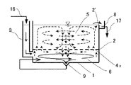
図1に、嫌気処理と好気処理を一体的に形成した場合の本発明に係る生物濾過装置の例を示す。
装置本体は、処理槽の底盤1と側壁2で、処理水の貯留部を形成する。
上部に接触濾過室5を形成して、接触濾材(微生物担体)7aを配置する。
接触濾過室の下部に曝気室6を形成し、接触濾過室5と曝気室6との間は、透過孔41aを有する隔壁4aにて分離している。
なお、透過孔41aの配置や大きさは、接触濾過室の水平方向の旋回流、曝気室から接触濾過室への処理水の供給量を考慮して決定する。
曝気室6の下部には、嫌気濾床室18を形成し微生物担体7bを配置し、嫌気濾床室18と曝気室6との間を透過孔41bを有する隔壁4bにて分離している。
また、注水管3を嫌気濾床室の底部付近に接続し、排水・汚水原水16を注入するが、原水が微生物担体の隙間を均一に流れるように、微生物担体7bと注水側との間を隔壁4cで分離している。
隔壁4cに形成する透過孔41cは均一に排水が上部に流れるように決定する。
処理水は、取水管12の吸水口9から循環ポンプ10で吸い込み、吐出ノズル15から曝気室内6に注入し水平方向の旋回流を発生させている。
循環配管の途中には微細気泡発生装置11を接続し、効率よく溶存酸素を添加する。
図2に、嫌気濾床室18から曝気室6に処理水が取り込まれる原理を模式的に示す。
隔壁4bの上側の曝気室に旋回流が生じているので、透過孔41bの上部は嫌気濾床側より負圧になっているので、曝気室側に取り込まれる。
この場合図2に示すように、透過孔付近の旋回流の流れを加速するのに隆起部42bを形成すると効果的である。
また、嫌気濾床室から曝気室に緩やかに取り込むには隔壁4bと微生物担体7bの間にある程度隙間を形成するのがよい。
なお、曝気室及び接触濾過室の構造については後述する。
FIG. 1 shows an example of the biological filtration device according to the present invention in which anaerobic treatment and aerobic treatment are integrally formed.
The main body of the apparatus forms a storage section of the processing water by the
A
An
The arrangement and size of the permeation holes 41a are determined in consideration of the horizontal swirling flow of the contact filtration chamber and the supply amount of the treated water from the aeration chamber to the contact filtration chamber.
In the lower part of the
Further, the
The
The treated water is sucked by the circulating
A
FIG. 2 schematically shows the principle that treated water is taken into the
Since a swirling flow is generated in the aeration chamber on the upper side of the
In this case, as shown in FIG. 2, it is effective to form a raised portion 42b for accelerating the flow of the swirling flow near the transmission hole.
In order to slowly take in the anaerobic filter bed chamber into the aeration chamber, it is preferable to form a gap to some extent between the
The structures of the aeration chamber and the contact filtration chamber will be described later.
次に、曝気室の下部に嫌気濾床室がない場合の本発明に係る生物濾過装置の実施例に基づいて、水平方向の旋回流及び、垂直方向の対流の発生する構造例を説明する。
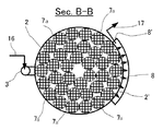
図3は、断面模式図、図4はその曝気室の水平断面図(Sec.A−A)、図5はその接触濾過室の水平断面図(Sec.B−B)、図6は生物濾過槽内部の処理水流方向を示すイメージ断面図である。
また、図7は原水を接触濾過槽上部中央から投入する場合の生物濾過装置の断面図である。
Next, an example of a structure in which a horizontal swirling flow and a vertical convection flow are generated will be described based on an embodiment of the biological filtration apparatus according to the present invention in a case where there is no anaerobic filter bed chamber below the aeration chamber.
3 is a schematic sectional view, FIG. 4 is a horizontal sectional view of the aeration chamber (Sec. AA), FIG. 5 is a horizontal sectional view of the contact filtration chamber (Sec. BB), and FIG. It is an image sectional view showing the treatment water flow direction inside the tank.
FIG. 7 is a cross-sectional view of the biological filtration device when raw water is supplied from the upper center of the contact filtration tank.
生物濾過槽底盤1と、生物濾過槽側壁2とで円筒形状の生物濾過槽を構成する。
生物濾過槽の形状は矩形の立方体でもよいが、水平方向の旋回流をスムーズに流すには円筒形が望ましい。
また、該生物濾過槽は透過性を持つ隔壁4aにより上部の接触濾過室5と下部の曝気室6に分割されており、隔壁4aは上下方向の処理水の移動を抑制している。
さらに、原水16を投入するための注水管3は隔壁2と同じ高さを有しており、原水16を曝気室6へ注いでいる。
The biological filtration
The shape of the biological filtration tank may be a rectangular cube, but a cylindrical shape is desirable in order to smoothly flow a horizontal swirling flow.
The biological filtration tank is divided into an upper
Further, the
原水16は曝気室6内の旋回流で処理水と撹拌混合されつつ、底盤1の中心部に設けられた吸水口9から吸引され、取水管12を通り循環ポンプ10の送流力で接続管13から微細気泡発生装置11に送られ、溶存酸素を十分に供された後に送水管14を経由して、吐出ノズル15から曝気室6へ戻され、旋回流となり再び処理水を曝気しつつ、撹拌混合する。
そして、この旋回流で曝気室内に堆積する剥離した生物膜や余剰汚泥は、底盤1の中央部へ引き寄せられ、吸水口9から循環ポンプ10、微細気泡発生装置11へ送られ、該循環ポンプ内の旋回噴流や微細気泡発生過程のキャビテーションにより粉砕される。
なお、微細気流発生装置11には気液混合ポンプを用いるが、特許第2646442号、特開2002−370095号には微細気泡発生装置11と循環ポンプ10とは一体となった構造のものが、また、特開2001−58142号には吐出ノズル15で微細気泡発生装置が記載されており、循環ポンプ10と微細気泡発生装置11を個別に用いずに、これら一体型のものを使用することも可能である。
The
Then, the separated biofilm and excess sludge deposited in the aeration chamber by this swirling flow are drawn to the center of the
Note that a gas-liquid mixing pump is used for the
曝気室6内の処理水は、前記のごとく循環しつつ旋回曝気されるが、一部は旋回流による遠心力と微細気流の上昇力により、透過性を有する隔壁4aを透過して接触濾過室5に入り、ゆっくりとした水平方向の旋回流と上下方向の対流により接触濾過材7aで生物濾過される。
接触濾過室5内の対流による上昇流で接触濾過室上部外縁の水面に達した処理水の一部は、放流溝8の部分で側壁2上部を切り下げた越流堰2’を越流して放流溝8に落ち、放流口8’から放流され放流水17となるが、ほとんどの処理水は水平方向に旋回しながら接触濾過材7aの中で生物濾過され、徐々に接触濾過室の中心部に引き寄せられて、下向きの対流に乗り接触濾過室内を循環し、一部は隔壁4aを透過して再び曝気室に戻る。
なお、接触濾過室の中心部において接触濾過材7aの配置を行わず通水路を作ることで、下向きの水流をスムーズにして、生物濾過槽全体の対流を促すこともできる。
The treated water in the
Part of the treated water reaching the water surface at the upper edge of the contact filtration chamber due to the upward flow due to the convection in the
In addition, by forming a water passage without arranging the
さらに、図7に示すごとく、注水管3を設けずに原水の投入を接触濾過室の上部中央付近から行い、また、吸水口9を底盤1上面から僅かに離して設置することで、生物濾過装置の構造を簡略化することも可能である。
Further, as shown in FIG. 7, raw water is introduced from the vicinity of the upper center of the contact filtration chamber without providing the
次に、図1に示した嫌気・好気処理連続型の生物濾過装置に基づいて、排水処理実験した結果例について説明する。
実験に用いた排水は、染色工場からの排水で、BOD:200〜300mg/L、
COD:300〜400mg/L、SS:20〜30mg/Lであった。
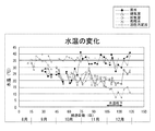
図8に、水温の変化を示す。
このグラフで、好気室とは接触濾過室を示し、嫌気室は嫌気濾床室を意味する。
なお、本実験においては、当染色工場にある活性汚泥処理槽と比較した。
染色工場からの排水のため、原水は比較的水温が高く、活性汚泥法はポンプによる曝気がされているので、冬季でも水温が高かった。
一方、実験プラントのおいては、小型で、循環ポンプや微細気泡発生装置の発生エネルギーも少ないので、冬季には20℃以下にまで下がった。
それでも、図9にSSの除去率変化、図10にTOC(全有機炭素量)除去率変化結果を示すように、安定して高い値を示した。
染色排水は、染色工程がバッチ処理であるために、排水組成変動が大きく、かつ、難分解性物質が多いにもかかわらず、TOC除去率65〜80%を確保したことは、活性汚泥法が水温30〜40℃の比較的高い水温でTOC除去率50〜80%であったのと比較すれば、優れた値である。
また、汚泥発生率を調査すると、除去TOC当たり1%以下であり、活性汚泥法のその値が20〜30%であることを考えると、汚泥発生が非常に少ない廃水処理方法である。
SS除去効果も図9に示すように活性汚泥法より優れていた。
この高いSS除去効果により、廃水処理後の脱色も活性汚泥法より優れていた。
図11に、実験装置内の硫酸塩濃度変化調査結果を示す。
嫌気室で硫酸塩還元が起こり、好気室で酸化が起きていることが確認できた。
Next, an example of the results of a wastewater treatment experiment based on the continuous anaerobic / aerobic treatment biological filtration device shown in FIG. 1 will be described.
The wastewater used for the experiment was wastewater from a dyeing factory, and had a BOD of 200 to 300 mg / L.
COD: 300 to 400 mg / L, SS: 20 to 30 mg / L.
FIG. 8 shows a change in water temperature.
In this graph, the aerobic chamber indicates a contact filtration chamber, and the anaerobic chamber means an anaerobic filter bed chamber.
In addition, in this experiment, it compared with the activated sludge treatment tank in this dyeing factory.
Raw water had a relatively high water temperature due to drainage from the dyeing factory, and the activated sludge method was aerated by a pump, so the water temperature was high even in winter.
On the other hand, in the experimental plant, the temperature was reduced to 20 ° C. or less in winter due to the small size and the low energy generated by the circulation pump and the fine bubble generator.
Nevertheless, as shown in FIG. 9, a change in the removal rate of SS and a change in the removal rate of TOC (total organic carbon) in FIG.
Since the dyeing wastewater has a large variation in wastewater composition and a large amount of hardly decomposable substances because the dyeing process is a batch process, the TOC removal rate of 65 to 80% was secured by the activated sludge method. This is an excellent value as compared with the case where the TOC removal rate is 50 to 80% at a relatively high water temperature of 30 to 40 ° C.
Further, when the sludge generation rate is investigated, it is 1% or less per removed TOC, and considering that the value of the activated sludge method is 20 to 30%, this is a wastewater treatment method that generates very little sludge.
The SS removal effect was also superior to the activated sludge method as shown in FIG.
Due to this high SS removal effect, decolorization after wastewater treatment was also superior to the activated sludge method.
FIG. 11 shows the results of the investigation of changes in the sulfate concentration in the experimental apparatus.
It was confirmed that sulfate reduction occurred in the anaerobic chamber and oxidation occurred in the aerobic chamber.
1 生物濾過槽の底盤
2 生物濾過槽の側壁
3 注水管
4a、4b、4c 隔壁
41a、41b、41c 隔壁の透過孔
5 接触濾過室
6 曝気室
7a 接触濾過材(微生物担体)
7b 嫌気室の微生物担体
8 放流溝
9 吸水口
10 循環ポンプ
11 微細気泡発生装置
12 取水管
13 接続管
14 送水管
15 吐出ノズル
16 原水(排水、汚水)
17 放流水
18 嫌気濾床室(嫌気室)
DESCRIPTION OF
7b Microbial carrier in
17 Discharged water 18 Anaerobic filter bed room (anaerobic room)
Claims (2)
Priority Applications (1)
| Application Number | Priority Date | Filing Date | Title |
|---|---|---|---|
| JP2004111704A JP4014581B2 (en) | 2003-04-08 | 2004-04-06 | Biological filtration device |
Applications Claiming Priority (2)
| Application Number | Priority Date | Filing Date | Title |
|---|---|---|---|
| JP2003103708 | 2003-04-08 | ||
| JP2004111704A JP4014581B2 (en) | 2003-04-08 | 2004-04-06 | Biological filtration device |
Publications (2)
| Publication Number | Publication Date |
|---|---|
| JP2004322084A true JP2004322084A (en) | 2004-11-18 |
| JP4014581B2 JP4014581B2 (en) | 2007-11-28 |
Family
ID=33512966
Family Applications (1)
| Application Number | Title | Priority Date | Filing Date |
|---|---|---|---|
| JP2004111704A Expired - Fee Related JP4014581B2 (en) | 2003-04-08 | 2004-04-06 | Biological filtration device |
Country Status (1)
| Country | Link |
|---|---|
| JP (1) | JP4014581B2 (en) |
Cited By (8)
| Publication number | Priority date | Publication date | Assignee | Title |
|---|---|---|---|---|
| JP2007175686A (en) * | 2005-12-26 | 2007-07-12 | N Ii T Kk | Anaerobic sprinkling filtration method and apparatus for organic waste water |
| JP2008029943A (en) * | 2006-07-27 | 2008-02-14 | Kanazawa Univ | Microorganism carrier and waste water treatment equipment |
| JP2010269203A (en) * | 2009-05-19 | 2010-12-02 | Nikkiso Co Ltd | Waste water treatment apparatus and method of controlling the same |
| WO2012050392A3 (en) * | 2010-10-15 | 2012-08-23 | 서울대학교산학협력단 | Container in which biofilm formation-inhibiting microorganisms are immobilized, and water treatment apparatus using membrane using same |
| KR101270906B1 (en) | 2011-09-29 | 2013-06-03 | 서울대학교산학협력단 | Fluidizable carrier with biofilm formation-inhibiting microorganisms immobilized therein and membrane water treatment apparatus using the same |
| CN105417688A (en) * | 2015-11-03 | 2016-03-23 | 重庆乐善环保科技有限公司 | Spherical filler and special-shaped carbon filler and their applications |
| JP2020054980A (en) * | 2018-10-04 | 2020-04-09 | 株式会社クボタ | Organic wastewater treatment apparatus |
| CN116535005A (en) * | 2023-06-29 | 2023-08-04 | 成都理工大学 | Intelligent synchronous nitrification and denitrification treatment system and method for domestic sewage |
Families Citing this family (1)
| Publication number | Priority date | Publication date | Assignee | Title |
|---|---|---|---|---|
| CN105254010A (en) * | 2015-11-03 | 2016-01-20 | 重庆乐善环保科技有限公司 | Reverse aeration sewage treatment pool and treatment method adopting treatment pool |
-
2004
- 2004-04-06 JP JP2004111704A patent/JP4014581B2/en not_active Expired - Fee Related
Cited By (12)
| Publication number | Priority date | Publication date | Assignee | Title |
|---|---|---|---|---|
| JP2007175686A (en) * | 2005-12-26 | 2007-07-12 | N Ii T Kk | Anaerobic sprinkling filtration method and apparatus for organic waste water |
| JP2008029943A (en) * | 2006-07-27 | 2008-02-14 | Kanazawa Univ | Microorganism carrier and waste water treatment equipment |
| JP2010269203A (en) * | 2009-05-19 | 2010-12-02 | Nikkiso Co Ltd | Waste water treatment apparatus and method of controlling the same |
| WO2012050392A3 (en) * | 2010-10-15 | 2012-08-23 | 서울대학교산학협력단 | Container in which biofilm formation-inhibiting microorganisms are immobilized, and water treatment apparatus using membrane using same |
| KR101270906B1 (en) | 2011-09-29 | 2013-06-03 | 서울대학교산학협력단 | Fluidizable carrier with biofilm formation-inhibiting microorganisms immobilized therein and membrane water treatment apparatus using the same |
| CN105417688A (en) * | 2015-11-03 | 2016-03-23 | 重庆乐善环保科技有限公司 | Spherical filler and special-shaped carbon filler and their applications |
| JP2020054980A (en) * | 2018-10-04 | 2020-04-09 | 株式会社クボタ | Organic wastewater treatment apparatus |
| WO2020071173A1 (en) * | 2018-10-04 | 2020-04-09 | 株式会社クボタ | Organic wastewater treatment apparatus |
| JP7105162B2 (en) | 2018-10-04 | 2022-07-22 | 株式会社クボタ | Organic wastewater treatment equipment |
| US11731891B2 (en) | 2018-10-04 | 2023-08-22 | Kubota Corporation | Organic wastewater treatment apparatus |
| CN116535005A (en) * | 2023-06-29 | 2023-08-04 | 成都理工大学 | Intelligent synchronous nitrification and denitrification treatment system and method for domestic sewage |
| CN116535005B (en) * | 2023-06-29 | 2023-09-01 | 成都理工大学 | Intelligent synchronous nitrification and denitrification treatment system and method for domestic sewage |
Also Published As
| Publication number | Publication date |
|---|---|
| JP4014581B2 (en) | 2007-11-28 |
Similar Documents
| Publication | Publication Date | Title |
|---|---|---|
| US20090127188A1 (en) | Waste gas/wastewater treatment equipment and method of treating waste gas/wastewater | |
| JP3336410B2 (en) | Apparatus and method for treating sewage and wastewater by biological reaction | |
| JP5366402B2 (en) | Water treatment method | |
| JPH07155758A (en) | Waste water treating device | |
| JP6072254B2 (en) | Water treatment equipment | |
| JP2004261711A (en) | Membrane separation activated sludge treatment apparatus and membrane separation activated sludge treatment method | |
| JP6497871B2 (en) | Method and apparatus for treating oil-containing wastewater | |
| JP4014581B2 (en) | Biological filtration device | |
| JP2010046602A (en) | Method of treating oil-containing waste water | |
| JP4409532B2 (en) | Apparatus for treating wastewater containing high-concentration nitrogen such as livestock wastewater and manure, and its treatment method | |
| JP2008246483A (en) | Apparatus for biological treatment of waste water | |
| JP2006205155A (en) | Anaerobic tank and waste water treatment system including the same | |
| JP2002307088A (en) | Wastewater treatment apparatus | |
| JP3913015B2 (en) | Washing wastewater treatment method | |
| WO2010101152A1 (en) | Device for membrane separation type activated-sludge treatment and method therefor | |
| JP4131734B2 (en) | Washing wastewater treatment equipment | |
| JP2006167551A (en) | Biological treatment apparatus | |
| JP2003053378A (en) | Method and device for treating water by using separation membrane | |
| JP2000094000A (en) | Immersion-type film-utilizing methane fermentation system | |
| JP2007190488A (en) | Membrane separation activated sludge treatment apparatus | |
| JP2005254207A (en) | Water treatment apparatus | |
| WO2007043134A1 (en) | Palm oil production wastewater treatment system and method of treating palm oil production wastewater | |
| JP2008221190A (en) | Wastewater treatment apparatus | |
| KR20020086777A (en) | Waste Water Treatment Equipment and Sequencing Batch Reactor System with using This | |
| JPWO2020021752A1 (en) | Garbage disposal equipment |
Legal Events
| Date | Code | Title | Description |
|---|---|---|---|
| A621 | Written request for application examination |
Free format text: JAPANESE INTERMEDIATE CODE: A621 Effective date: 20070307 |
|
| A521 | Written amendment |
Free format text: JAPANESE INTERMEDIATE CODE: A821 Effective date: 20070308 |
|
| A871 | Explanation of circumstances concerning accelerated examination |
Free format text: JAPANESE INTERMEDIATE CODE: A871 Effective date: 20070417 |
|
| A975 | Report on accelerated examination |
Free format text: JAPANESE INTERMEDIATE CODE: A971005 Effective date: 20070611 |
|
| A131 | Notification of reasons for refusal |
Free format text: JAPANESE INTERMEDIATE CODE: A131 Effective date: 20070620 |
|
| A521 | Written amendment |
Free format text: JAPANESE INTERMEDIATE CODE: A523 Effective date: 20070803 |
|
| TRDD | Decision of grant or rejection written | ||
| A01 | Written decision to grant a patent or to grant a registration (utility model) |
Free format text: JAPANESE INTERMEDIATE CODE: A01 Effective date: 20070829 |
|
| A61 | First payment of annual fees (during grant procedure) |
Free format text: JAPANESE INTERMEDIATE CODE: A61 Effective date: 20070911 |
|
| FPAY | Renewal fee payment (event date is renewal date of database) |
Free format text: PAYMENT UNTIL: 20100921 Year of fee payment: 3 |
|
| R150 | Certificate of patent or registration of utility model |
Free format text: JAPANESE INTERMEDIATE CODE: R150 |
|
| FPAY | Renewal fee payment (event date is renewal date of database) |
Free format text: PAYMENT UNTIL: 20100921 Year of fee payment: 3 |
|
| FPAY | Renewal fee payment (event date is renewal date of database) |
Free format text: PAYMENT UNTIL: 20110921 Year of fee payment: 4 |
|
| FPAY | Renewal fee payment (event date is renewal date of database) |
Free format text: PAYMENT UNTIL: 20110921 Year of fee payment: 4 |
|
| S111 | Request for change of ownership or part of ownership |
Free format text: JAPANESE INTERMEDIATE CODE: R313117 |
|
| FPAY | Renewal fee payment (event date is renewal date of database) |
Free format text: PAYMENT UNTIL: 20110921 Year of fee payment: 4 |
|
| R350 | Written notification of registration of transfer |
Free format text: JAPANESE INTERMEDIATE CODE: R350 |
|
| FPAY | Renewal fee payment (event date is renewal date of database) |
Free format text: PAYMENT UNTIL: 20110921 Year of fee payment: 4 |
|
| FPAY | Renewal fee payment (event date is renewal date of database) |
Free format text: PAYMENT UNTIL: 20110921 Year of fee payment: 4 |
|
| FPAY | Renewal fee payment (event date is renewal date of database) |
Free format text: PAYMENT UNTIL: 20120921 Year of fee payment: 5 |
|
| FPAY | Renewal fee payment (event date is renewal date of database) |
Free format text: PAYMENT UNTIL: 20120921 Year of fee payment: 5 |
|
| FPAY | Renewal fee payment (event date is renewal date of database) |
Free format text: PAYMENT UNTIL: 20130921 Year of fee payment: 6 |
|
| LAPS | Cancellation because of no payment of annual fees |