JP2004321428A - Game machine - Google Patents
Game machine Download PDFInfo
- Publication number
- JP2004321428A JP2004321428A JP2003119300A JP2003119300A JP2004321428A JP 2004321428 A JP2004321428 A JP 2004321428A JP 2003119300 A JP2003119300 A JP 2003119300A JP 2003119300 A JP2003119300 A JP 2003119300A JP 2004321428 A JP2004321428 A JP 2004321428A
- Authority
- JP
- Japan
- Prior art keywords
- variable display
- display
- determination
- time
- specific
- Prior art date
- Legal status (The legal status is an assumption and is not a legal conclusion. Google has not performed a legal analysis and makes no representation as to the accuracy of the status listed.)
- Withdrawn
Links
Images


Landscapes
- Pinball Game Machines (AREA)
- Display Devices Of Pinball Game Machines (AREA)
Abstract
Description
【0001】
【発明の属する技術分野】
本発明は、所定の始動条件の成立に基づいて各々が識別可能な複数種類の識別情報の可変表示を行って表示結果を導出表示する可変表示装置を含み、前記識別情報の表示結果が予め定められた特定表示結果となったときに遊技者にとって有利な特定遊技状態に制御する遊技機に関するものである。
【0002】
【従来の技術】
従来、所定の始動条件の成立に基づいて各々が識別可能な複数種類の識別情報の可変表示を行って表示結果を導出表示する可変表示装置を備えた遊技機、例えば、弾球遊技機において、遊技制御手段が、可変表示装置の可変表示開始前に可変表示時間および変動態様(リーチあり・なし、再変動あり・なし、等)を含んだ変動パターンコマンドと、停止図柄を特定可能な表示制御コマンドと、を表示制御手段に送信し、これらのコマンドを受信した表示制御手段が図柄の差し替え制御を行った後、可変表示時間が終了した時点で遊技制御手段が全図柄停止を示す表示制御コマンドを送信して表示制御手段によって確定図柄の表示を行わせるものがあった(例えば、特許文献1参照)。
【0003】
【特許文献1】
特開2001−17674号公報 (第9−11頁、第21図)
【0004】
【発明が解決しようとする課題】
上記した構成の遊技機においては、1つの変動パターンに対して停止図柄を特定可能な表示制御コマンドを変えることで複数の演出を実行することが可能となったため、遊技制御手段から表示制御手段に送信する変動パターンの数が減り、遊技制御手段の図柄表示に関する制御の負担を軽減させることが可能となったが、同一の変動パターン(リーチパターン)に対して、再抽選ありの場合と再抽選なしの場合との2種類備えていたため、変動パターンコマンドを大幅に減少させるものではなく、遊技制御手段におけるデータ量も大幅に減少させることができなかった。更に、表示制御手段においても、遊技制御手段から送信される変動パターンそれぞれにデータを持つ必要があったためデータ量が多くなってしまっていた。本発明は、上記した事情に鑑みなされたもので、その目的とするところは、1つの変動パターンの可変表示時間を変化させることにより複数の演出に用いることができる遊技機を提供することにある。
【0005】
【課題を解決するための手段】
上記した目的を達成するために、請求項1に係る発明においては、所定の始動条件(例えば、始動入賞口14への始動入賞)の成立に基づいて各々が識別可能な複数種類の識別情報(例えば、特別図柄10a)の可変表示を行って表示結果を導出表示する可変表示装置(例えば、可変表示装置8)を含み、前記識別情報の表示結果が予め定められた特定表示結果(例えば、大当り図柄)となったときに遊技者にとって有利な特定遊技状態(例えば、大当り遊技状態)に制御する遊技機であって、遊技の進行を制御する遊技制御手段(例えば、CPU56等)と、該遊技制御手段から送信された制御信号(例えば、演出制御コマンド)に基づいて前記可変表示装置における前記識別情報の可変表示を含む表示を制御する表示制御手段(例えば、演出制御用CPU111等)と、を備え、前記遊技制御手段は、前記表示制御手段に制御信号を送信する信号送信手段(例えば、ステップS87で実行するコマンドセット処理)と、前記始動条件の成立に基づいて前記表示結果をその導出表示以前に決定する表示結果事前決定手段(例えば、ステップS300、S301)と、前記始動条件の成立に基づいて前記可変表示装置に表示結果を導出表示する際に実行される識別情報の可変表示パターン(例えば、変動パターン)をその導出表示以前に特定可変表示パターン(例えば、変動パターン3〜8、11〜20)を含む予め定められた複数の可変表示パターンの内より決定する可変表示パターン事前決定手段(例えば、ステップS82、SA82)と、可変表示開始からの可変表示時間(例えば、変動時間)を計測する可変表示時間計測手段(例えば、特別図柄プロセスタイマ)と、該可変表示時間計測手段によって前記可変表示パターン事前決定手段によって決定された可変表示パターンに基づく可変表示時間が経過したことを判定する可変表示時間判定手段(例えば、ステップS303にて特別図柄プロセスタイマがタイムアウトしたか否かを判定する処理)と、を含み、前記複数の可変表示パターンを示す特定可変表示データを含む複数の可変表示データを記憶するメインデータ記憶手段(例えば、ROM54)をさらに含み、前記可変表示パターン事前決定手段は、前記特定可変表示パターンと決定したときに該特定可変表示パターンを示す特定可変表示データを選択する可変表示データ選択手段(例えば、ステップS85、SA87)を含み、前記信号送信手段は、前記可変表示データ選択手段によって選択された可変表示データを指定する可変表示データ信号(例えば、変動パターンコマンド02H,03H,06H〜08H)と、前記表示結果事前決定手段により決定された前記表示結果の導出表示を指示する確定信号(例えば、確定信号)と、を送信する機能を有し、前記表示制御手段は、前記遊技制御手段から送信される制御信号を受信する信号受信手段(例えば、I/Oポート部114)と、前記可変表示データ信号に対応して設けられる可変表示パターンデータ(例えば、プロセスデータ113a)を含むデータを記憶するサブデータ記憶手段(例えば、ROM113)と、前記可変表示データ信号を受信したことに基づいて当該可変表示データ信号に対応する可変表示パターンデータを前記サブデータ記憶手段から選択する可変表示パターン選択手段(例えば、ステップS801b、SA801b)と、前記確定信号を受信したことに基づいて前記表示結果を導出表示する導出表示手段(例えば、ステップS804)と、を含み、前記信号送信手段は、前記可変表示データ信号として前記特定可変表示データを指定する信号を送信したときには前記可変表示時間計測手段によって計測された可変表示時間(例えば、変動パターンコマンドに基づく変動時間)が前記可変表示パターン事前決定手段の決定結果に応じた可変表示時間(例えば、変動パターンに基づく変動時間)を経過したことを前記可変表示時間判定手段が判定したときに前記確定信号を送信する判定時確定信号送信手段(例えば、ステップS304)を含み、前記導出表示手段は、前記信号受信手段によって前記可変表示データ信号として前記特定可変表示データを指定する信号を受信したときには、前記特定可変表示データを指定する信号の受信によって可変表示時間として設定された時間(例えば、変動パターンコマンドに基づく変動時間)が経過していなくても前記判定時確定信号送信手段によって送信された前記確定信号を受信したことに基づき前記表示結果を導出表示することを特徴とする。このように構成することにより、複数の可変表示パターンを含む可変表示パターンに対し、確定信号の送信タイミングによって複数の演出に用いることが可能となるため、データ量および信号種類の軽減を図ることができる。
【0006】
また、請求項2に係る発明においては、前記特定表示結果は予め定められた複数種類の特定表示結果(例えば、確変図柄、非確変図柄)を含み、前記特定可変表示データは、前記表示結果事前決定手段により表示結果を前記特定表示結果とすることが決定されたときに、当該特定表示結果と同一または当該特定表示結果と異なる特定表示結果(例えば、仮停止図柄)を一旦導出したあとに前記表示結果事前決定手段により決定された特定表示結果を導出表示させる再抽選演出を実行する再抽選可変表示パターン(例えば、変動パターン14、18、20)と、該再抽選演出を実行しない非再抽選可変表示パターン(例えば、変動パターン11〜13、15〜17、19)を含む再抽選データ(例えば、プロセスデータ113a)とすることを特徴とする。このように構成することにより、複数の可変表示パターンを含む可変表示パターンに対し、確定信号の送信タイミングによって複数の演出に用いることが可能となるため、データ量および信号種類の軽減を図ることができる。
【0007】
また、請求項3に係る発明においては、前記複数種類の特定表示結果は、前記特定遊技状態終了後に該特定遊技状態とは異なる遊技状態であって遊技者にとって有利な特別遊技状態(例えば、確変状態)となる第1特定表示結果(例えば、確変図柄)と、前記特定遊技状態終了後に通常遊技状態となる第2特定表示結果(例えば、非確変図柄)と、を含み、前記遊技制御手段は、前記表示結果事前決定手段により前記第1特定表示結果とすることが決定されたときに前記可変表示パターン事前決定手段により前記再抽選可変表示パターンとするか否かの決定に用いる第1特定判定テーブル(例えば、確変大当り時変動パターンテーブル)と、前記表示結果事前決定手段により前記第2特定表示結果とすることが決定されたときに前記可変表示パターン事前決定手段により前記再抽選可変表示パターンとするか否かの決定に用いる第2特定判定テーブル(例えば、非確変大当り時変動パターンテーブル)と、を備え、前記第1特定判定テーブルにおける前記再抽選可変表示パターンを行う旨の決定がなされる割合は前記第2特定判定テーブルにおける前記再抽選可変表示パターンを行う旨の決定がなされる割合よりも高くなるように再抽選可変表示パターンを行う決定に用いる判定データを構成することを特徴とする。このように構成することにより、表示結果事前決定手段により第1特定表示結果を表示することが決定されたときには再抽選演出が実行されやすくなり、第1特定表示結果を表示する前には再抽選演出を実行することにより、遊技者に遊技に対する興趣を長引かせることができ、興趣を向上させることができる。
【0008】
また、請求項4に係る発明においては、前記特定可変表示データによって特定される異なる複数の可変表示パターンは異なる可変表示時間が予め定められており、前記遊技制御手段は、前記表示結果事前決定手段によって前記特定表示結果とすることが決定されたときに前記可変表示パターン事前決定手段により異なる複数の可変表示パターンのうちいずれの可変表示パターンとするかの決定に用いる当選時判定テーブル(例えば、確変大当り時変動パターンテーブルおよび非確変大当り時変動パターンテーブル)と、前記表示結果事前決定手段によって前記非特定表示結果とすることが決定されたときに前記可変表示パターン事前決定手段により異なる複数の可変表示パターンのうちいずれの可変表示パターンとするかの決定に用いる非当選時判定テーブル(例えば、リーチ時変動パターンテーブルおよびはずれ時変動パターンテーブル)と、を備え、前記当選時判定テーブルにおける前記複数の可変表示パターンのうち前記可変表示時間が短い(例えば、変動パターンコマンドに基づく変動時間よりも短い)可変表示パターンに決定される割合は、前記非当選時判定テーブルにおける前記可変表示時間が短い可変表示パターンに決定される割合よりも低くなるように可変表示パターンの決定に用いる判定データを構成することを特徴とする。このように構成することにより、表示結果事前決定手段により特定表示結果を表示することが決定されたときには、可変表示時間が長くなるような可変表示パターンが選択されやすくなり、可変表示時間が長くなることにより、遊技者に遊技に対する興趣を長引かせることができ、興趣を向上させることができる。
【0009】
また、請求項5に係る発明においては、前記信号送信手段は、前記表示結果事前決定手段によって決定された表示結果を指示する識別情報信号(特別図柄指定コマンド)を送信する機能をさらに有し、前記表示制御手段は、前記識別情報信号を受信し、前記判定時確定信号送信手段によって送信された前記確定信号を受信したことに基づいて当該可変表示中の識別情報を前記識別情報信号によって指定された識別情報に差し替える識別情報差替手段(例えば、ステップS804)を有することを特徴とする。このように構成することにより、表示制御手段は、識別情報信号を受信したことによって当該識別情報信号によって指定される識別情報を準備し、確定信号に基づいて可変表示中の識別情報と差し替えることにより、予め定められた表示結果を確定表示結果として表示することが可能となる。
【0010】
【発明の実施の形態】
以下、本発明の一実施形態について、図面を参照して説明する。まず、遊技機の一例である弾球遊技機1の全体の構成について説明する。図1は弾球遊技機1を正面からみた正面図である。なお、ここでは、遊技機の一例として弾球遊技機を示すが、本発明は弾球遊技機に限られず、例えばコイン遊技機やスロット機等であってもよい。
【0011】
弾球遊技機1は、縦長の方形状に形成された外枠(図示せず)と、外枠の内側に開閉可能に取り付けられた遊技枠とで構成される。また、弾球遊技機1は、遊技枠に開閉可能に設けられている額縁状に形成されたガラス扉枠2を有する。遊技枠は、外枠に対して開閉自在に設置される前面枠(図示せず)と、機構部品等が取り付けられる機構板と、それらに取り付けられる種々の部品(後述する遊技盤6を除く。)と、を含む構造体である。
【0012】
図1に示すように、弾球遊技機1は、額縁状に形成されたガラス扉枠2を有する。ガラス扉枠2の下部表面には打球供給皿(上皿)3がある。打球供給皿3の下部には、打球供給皿3に収容しきれない遊技球を貯留する余剰球受皿4、打球を発射する打球操作ハンドル(操作ノブ)5が設けられている。ガラス扉枠2の背面には、遊技盤6が着脱可能に取り付けられている。なお、遊技盤6は、それを構成する板状体と、その板状体に取り付けられた種々の部品とを含む構造体である。また、遊技盤6の前面には打ち込まれた遊技球が流下可能な遊技領域7が形成されている。
【0013】
遊技領域7の中央付近には、遊技盤に設けられ所定の始動条件の成立(例えば、始動入賞)に基づいて各々が識別可能な複数種類の識別情報(例えば、特別図柄10a)の可変表示を行って表示結果を導出表示する可変表示装置8を備えている。本実施形態では、可変表示装置8はLCD表示装置により構成され、その中央には飾り図柄9a〜9cを可変表示する複数の表示領域(本実施形態では3つ)を有する飾り図柄表示部9が設けられ、該飾り図柄表示部9の右下側には特別図柄10aを可変表示する特別図柄表示部10が設けられている。本実施形態における特別図柄表示部10では、1つの表示領域によって表示される特別図柄10aの比較的単調な可変表示を行なっている。飾り図柄表示部9は、この特別図柄表示部10で行われる可変表示の内容を、より演出効果を高めて遊技者に表示するための可変表示装置である。
【0014】
なお、本実施形態における弾球遊技機1は、後述する表示結果事前決定手段が特別図柄表示部10の表示結果を予め定められた特定表示結果とすることを決定したときに特別図柄表示部10に特定表示結果を表示した後に遊技者にとって有利な特定遊技状態としての大当り遊技状態に制御する機能を有する。また、この特別図柄表示部10の表示結果と飾り図柄表示部9の表示結果とは対応している。例えば、特別図柄表示部10の表示結果が大当り状態を示す結果になる場合には、飾り図柄表示部9の表示結果も大当り状態を示す結果になる。また、特別図柄表示部10の表示結果が大当り状態以外のはずれ状態を示す場合には、飾り図柄表示部9の表示結果もはずれ状態を示す結果となる。
【0015】
また、特定表示結果は、第1特定表示結果(確変図柄)と第1特定表示結果以外の第2特定表示結果(非確変図柄)を含み、本実施形態における弾球遊技機1は、後述する表示結果事前決定手段が表示結果を第1特定表示結果とすることを決定したときに飾り図柄表示部9に第1特定表示結果を表示した後に特定遊技状態(大当り遊技状態)に制御し、大当り遊技状態終了後に表示結果が通常遊技状態より大当り状態となり易い(大当りとなる確率が高い)特別遊技状態としての確変状態に制御する機能も有している。なお、通常遊技状態とは、特別遊技状態および特定遊技状態とは異なる遊技状態のことである。
【0016】
なお、特別遊技状態として時短状態に制御することにより、遊技者にとって更に有利な状態とするようにしてもよい。時短状態では、特別図柄表示部10において特別図柄10aの変動表示(可変表示)が所定回数(例えば、100回)実行されるまで、可変表示装置8の特別図柄表示部10および普通図柄表示器13において可変表示時間(変動時間)が通常遊技状態より短縮される。更に、可変入賞球装置15において、開放時間と開放回数とのうちの一方又は双方が通常遊技状態より高められる。可変入賞球装置15の開放時間又は開放回数が通常遊技状態より高められることにより、始動入賞口14への始動入賞が起こりやすくなり、所定期間内での特別図柄表示部10における特別図柄10aの可変表示回数が増加して特別図柄10aが当り図柄となる確率が通常遊技状態より高まるため、遊技者にとって更に有利な状態となる。
【0017】
また、特別遊技状態は上記したものに限らず、遊技者に有利となる遊技制御を特別遊技状態とすればよい。以下、この遊技制御を大当りに直接的には係わらないもの(特定遊技状態中以外)と大当りに直接的に係わるもの(特定遊技状態中)とに分けて説明する。即ち、特定遊技状態に加える特別遊技状態とは、特定遊技状態とは別の特別遊技状態のことであってもよいし、また特定遊技状態を含む特別遊技状態のことであってもよい。先ず、大当りに直接的には係わらない遊技制御としては、特別図柄10a乃至普通図柄に対しての時間短縮(時短)制御又は確率変動(確変)制御、電役(例えば、可変入賞球装置15)の開放期間の延長制御、特別図柄乃至普通図柄に対しての始動通過領域の増設制御(例えば、遊技盤6に設置される入賞口29,30,33,39等を特別図柄10aの始動入賞口として設定変更する制御)、賞球数の増加制御(例えば、入賞に伴う賞球を通常遊技状態時の13個から15個に増加する制御)、あるいは所定領域への通過率向上制御(例えば、始動入賞口14の上流側に打玉規制装置を設け、該打玉規制装置の作動により始動入賞率を向上する制御)を特別遊技状態とすることができ、さらには始動入賞に基づいて可変表示される図柄の停止図柄が所定の図柄の組合せになると開放する所定の電動役物への入賞があると所定の権利が発生又は継続する第3種弾球遊技機に本発明を適用した場合には、特定領域への入賞率向上制御を特別遊技状態としてもよい。一方、大当りに直接的に係わる遊技制御としては、ラウンド上限数の向上制御、カウント上限数の向上制御、開閉板20の開放延長制御、あるいは開閉板20によって開放された大入賞口への入賞に伴う賞球数の増加制御を特別遊技状態とすることができる。なお、上記した遊技制御を組合せて特別遊技状態とすることもできるのは言うまでもない。さらには、特別遊技状態への突入(所定条件の成立)及び終了の契機については、本実施形態中に記載のものに限定せず、乱数、遊技履歴(例えば、時間、リーチ回数、所定入賞口への入賞回数、通過回数等)、入賞、及びサブゲーム(例えば、ジャンケンなどで遊技者自身が選択できるものを含む)の4つの要素のうちいずれか1つ乃至任意の組合せを突入契機乃至終了契機に設定するものであればよい。
【0018】
可変表示装置8の上部には、7セグメントLEDにより構成された普通図柄表示器13が設けられている。この普通図柄表示器13は、普通図柄と呼ばれる複数種類の識別情報を可変表示可能なものである。また、可変表示装置8には、始動入賞口14に入り始動条件が成立したが未だ可変表示装置8の開始条件(例えば、前回の特別図柄10aの可変表示および大当り遊技状態の終了)が成立していない始動条件の成立回数である始動記憶数を記憶する始動記憶手段(例えば、始動記憶バッファ55c:主基板31のRAM55により始動記憶数を記憶する機能)に記憶された始動記憶数を表示する始動記憶数表示手段としての4つの始動記憶表示エリア(図示しない)が設けられている。この始動記憶表示エリアは、有効始動入賞(本実施形態では、始動記憶数が4未満のときの始動入賞)がある毎に、表示色を変化(例えば青色表示から赤色表示に変化)させ、可変表示装置8の可変表示が開始される毎に、表示色が変化している始動記憶表示エリアを1減らす。すなわち表示色をもとの状態に戻す。
【0019】
なお、この実施形態では有効始動入賞数は4つとなっているが、これに限られるものではない。例えば、有効始動入賞数を30としてもよく。この場合には、30回分の始動記憶数を表示できるように始動記憶表示エリアを構成してもよく、また、30回分の始動記憶のうち所定数(例えば、5つ)のみ表示するようにしてもよい。
【0020】
また、可変表示装置8においては飾り図柄表示部9と始動記憶表示エリアとが区分けされて設けられているので、可変表示中も始動記憶数が表示された状態とすることができる。また、始動記憶表示エリアを飾り図柄表示部9の一部に設けるようにしてもよく、この場合には、可変表示中は始動記憶数の表示を中断するようにすればよい。また、この実施の形態では、始動記憶表示エリアを可変表示装置8に設けるようにしているが、始動記憶数を表示する表示器(特別図柄始動記憶表示器)を可変表示装置8とは別個に設けるようにしてもよい。
【0021】
可変表示装置8の下方には、始動入賞口14を有する可変入賞球装置15が設けられている。始動入賞口14に入った入賞球は、遊技盤6の背面に導かれ、始動口スイッチによって検出される。また、始動入賞口14の下部には開閉動作を行う可変入賞球装置15が設けられている。可変入賞球装置15は、ソレノイド16によって開状態とされる。
【0022】
可変入賞球装置15の下部には、上述した特定遊技状態(大当り遊技状態)においてソレノイド21によって開状態とされる開閉板20が設けられている。開閉板20は大入賞口を開閉する手段である。開閉板20から遊技盤6の背面に導かれた入賞球のうち、一方(V入賞領域)に入った入賞球はV入賞スイッチで検出され、もう一方(10カウント入賞領域)に入った入賞球はカウントスイッチで検出される。遊技盤6の背面には、大入賞口内の経路を切り換えるためのソレノイド(図示しない)も設けられている。
【0023】
ゲート32に遊技球が入賞しゲートスイッチで検出されると、普通図柄表示器13の始動記憶である普通図柄始動記憶が上限に達していなければ、所定の乱数値が抽出される。そして、普通図柄表示器13において表示状態が変化する可変表示を開始できる状態であれば、普通図柄表示器13の可変表示が開始される。普通図柄表示器13において表示状態が変化する可変表示を開始できる状態でなければ、普通図柄始動記憶の値が1増やされる。普通図柄表示器13の近傍には、普通図柄始動記憶数を表示する所定数(この実施の形態では4つ)のLEDによる表示部を有する普通図柄始動記憶表示器(図示しない)が設けられている。ゲート32への入賞がある毎に、普通図柄始動記憶表示器は点灯するLEDを1増やす。そして、普通図柄表示器13の可変表示が開始される毎に、点灯するLEDを1減らす。なお、特別図柄10aと普通図柄とを一つの可変表示装置で可変表示するように構成することもできる。その場合には、特別可変表示領域と普通可変表示領域とは1つの可変表示装置で実現される。
【0024】
この実施の形態では、○と×の付された左右のランプ(点灯時に図柄が視認可能になる)が交互に点灯することによって普通図柄の可変表示が行われ、可変表示は所定時間(例えば29.2秒)継続する。そして、可変表示の終了時に○の付された左側のランプが点灯すれば当りとなる。当りとするか否かは、ゲート32に遊技球が入賞したときに抽出された乱数の値が所定の当り判定値と一致したか否かによって決定される。普通図柄表示器13における可変表示の表示結果が当りである場合に、可変入賞球装置15が所定回数、所定時間だけ開状態になって遊技球が入賞しやすい状態になる。すなわち、可変入賞球装置15の状態は、普通図柄の停止図柄が当り図柄である場合に、遊技者にとって不利な状態から有利な状態に変化する。
【0025】
更に、特別遊技状態としての確変状態では、可変表示装置8の特別図柄表示部10における特別図柄10aの停止図柄が当り図柄(特定表示結果、例えば「7」)になる確率が通常遊技状態より高められるとともに、特別図柄10aの可変表示時間(変動時間)が通常遊技状態より短縮される。更に、普通図柄表示器13において、停止図柄が当り図柄になる確率が通常遊技状態より高められるとともに、可変入賞球装置15の開放時間と開放回数とのうちの一方又は双方が通常遊技状態より高められる。これにより遊技者にとって更に有利になる。また、確変状態等の所定の状態では、普通図柄表示器13における可変表示時間(変動時間)が通常遊技状態より短縮されることによって、遊技者にとって更に有利になるようにしてもよい。
【0026】
遊技盤6の遊技領域7の左右周辺には、遊技中に点滅表示される装飾ランプ25が設けられ、下部には、入賞しなかった打球が取り込まれるアウト口26がある。また、遊技領域7の外側の左右上部には、所定の音声出力として効果音や音声を発声する2つのスピーカ27が設けられている。遊技領域7の外周上部、外周左部および外周右部には、前面枠に設けられた天枠ランプ40、枠ランプ左41および枠ランプ右42が設けられている。また、可変表示装置8の左右側方には、盤ランプ左11および盤ランプ右12が設けられている。そして、この例では、枠ランプ左41の近傍に、賞球残数があるときに点灯する賞球ランプ51が設けられ、枠ランプ右42の近傍に、補給球が切れたときに点灯する球切れランプ52が設けられている。
【0027】
次に、リーチ状態について説明する。本実施形態におけるリーチ状態とは、停止した図柄が大当り図柄の一部を構成しているときに未だ停止していない図柄については可変表示(変動表示)が行われていること、および全てまたは一部の図柄が大当り図柄の全てまたは一部を構成しながら同期して変動表示している状態である。
【0028】
本実施形態では、予め定められた複数の表示領域としての飾り図柄表示部9に、予め定められた図柄が停止することで大当りとなる有効ラインが定められ、その有効ライン上の一部の表示領域に予め定められた図柄が停止しているときに未だ停止していない有効ライン上の表示領域において変動表示が行われている状態(例えば、左、中、右の表示領域のうち左、右の表示領域には大当り図柄の一部となる(例えば「7」)が停止表示されている状態で右の表示領域は未だ変動表示が行われている状態)、および有効ライン上の表示領域の全てまたは一部の図柄が大当り図柄の全てまたは一部を構成しながら同期して変動表示している状態(例えば、左、中、右の表示領域の全てに変動表示が行われており、常に同一の図柄が揃っている状態で変動表示が行われている状態)をいう。
【0029】
本実施形態における特別図柄表示部10は、1つの表示領域によって構成されているため、リーチ表示されることはない。しかし、飾り図柄表示部9においてリーチ演出の行われている間は特別図柄表示部10は変動表示を行っており、特別図柄表示部10の変動停止と共に飾り図柄表示部9の変動が停止する。また、特別図柄表示部10を複数の表示領域で構成してもよく、その場合、リーチ状態とするようにしてもよい。
【0030】
また、リーチの際に、通常と異なる演出がランプや音で行われることがある。この演出をリーチ演出という。また、リーチの際に、キャラクタ(人物等を模した演出表示であり、図柄とは異なるもの)を表示させたり、背景の表示態様を変化させたりすることがある。このキャラクタの表示や背景の表示態様の変化をリーチ演出表示という。
【0031】
打球発射装置から発射された遊技球は、打球レールを通って遊技領域7に入り、その後、遊技領域7を下りてくる。打球が始動入賞口14に入り始動口スイッチで検出されると、特別図柄10aの可変表示を開始できる状態であれば(例えば、大当り遊技終了又は前回の可変表示の終了)、特別図柄表示部10において特別図柄10aの可変表示(変動表示)を開始すると共に、飾り図柄表示部9において飾り図柄9a〜9cの可変表示を開始する。特別図柄10aの可変表示を開始できる状態でなければ、始動記憶数を1増やす。
【0032】
特別図柄表示部10における特別図柄10aの可変表示は、一定時間が経過したときに停止し、特別図柄表示部10の変動停止と共に飾り図柄表示部9の変動が停止する。停止時の特別図柄10aが大当り図柄(特定表示結果)となるときには、飾り図柄表示部9の表示結果も大当り図柄(特定表示結果)となり、大当り遊技状態に移行する。すなわち、開閉板20が、一定時間経過するまで、または、所定個数(例えば10個)の打球が入賞するまで開放する。そして、開閉板20の開放中に打球がV入賞領域に入賞しV入賞スイッチで検出されると、継続権が発生し開閉板20の開放が再度行われる。継続権の発生は、所定回数(例えば15ラウンド)許容される。
【0033】
停止時の特別図柄表示部10における特別図柄10aが確率変動を伴う大当り図柄(第1特定表示結果:確変図柄)である場合には、飾り図柄表示部9における飾り図柄9a〜9cの組み合わせも確率変動を伴う大当り図柄(第1特定表示結果:確変図柄)となり、大当り遊技状態に制御され、大当り遊技状態終了後に次に大当りとなる確率が通常遊技状態より高くなる。すなわち、確変状態という遊技者にとって更に有利な状態(特別遊技状態)となる。
【0034】
図2は、本実施形態に係る弾球遊技機1の回路構成の概要を表したブロック図である。主基板31には、プログラムに従って弾球遊技機1を制御する基本回路53が搭載されている。基本回路53は、ゲーム制御用のプログラム等を記憶するROM54、ワークメモリとして使用される記憶手段としてのRAM55、プログラムに従って遊技の信号を制御する遊技制御手段としてのCPU56及び演出制御基板80等に制御信号を送信するI/Oポート部57を含む。この実施の形態では、ROM54、RAM55、I/Oポート部57はCPU56に内蔵されている。すなわち、CPU56は、1チップマイクロコンピュータである。なお、1チップマイクロコンピュータは、少なくともRAM55が内蔵されていればよく、ROM54及びI/Oポート部57は外付けであっても内蔵されていてもよい。なお、CPU56はROM54に格納されているプログラムに従って制御を実行するので、以下、CPU56が実行する(または、処理を行う)ということは、具体的には、CPU56がプログラムに従って制御を実行することである。このことは、主基板31以外の他の基板に搭載されているCPUについても同様である。
【0035】
なお、図2には示されていないが、ゲートスイッチ、始動口スイッチ、V入賞スイッチ、カウントスイッチ、満タンスイッチ、カウントスイッチ短絡信号及びクリアスイッチからの信号を基本回路53に与えるスイッチ回路、可変入賞球装置15を開閉するソレノイド16、開閉板20を開閉するソレノイド21等を基本回路53からの指令に従って駆動するソレノイド回路、電源投入時に基本回路53をリセットするためのシステムリセット回路、基本回路53から与えられるデータに従って、大当りの発生を示す大当り情報、特別図柄表示部10における特別図柄10aの可変表示開始に利用された始動入賞球の個数を示す有効始動情報、確率変動が生じたことを示す確変情報等の情報出力信号をホールコンピュータ等の外部装置に対して出力する情報出力回路、も主基板31に搭載されている。
【0036】
また、RAM(CPU内蔵RAMであってもよい。)55の一部または全部が、電源基板において作成されるバックアップ電源によってバックアップされているバックアップRAMである。すなわち、遊技機に対する電力供給が停止しても、所定期間は、RAM55の一部または全部の内容は保存される。
【0037】
また、主基板31に搭載されるRAM55には、後述する大当りフラグを記憶する大当りフラグメモリ55aと、特別図柄表示部10にて特別図柄10aの変動(可変表示)が変動パターンに基づく変動時間(可変表示時間)で行われるように制御するための特別図柄プロセスタイマ(可変表示時間計測手段)55bと、始動入賞口14に入り始動条件が成立したが未だ可変表示装置8の開始条件(例えば、前回の特別図柄10aの可変表示および大当り遊技状態の終了)が成立していない始動条件の成立回数である始動記憶数を記憶する始動記憶手段としての始動記憶バッファ55cと、が設けられている。また、ROM54には、後述する変動パターンコマンド54aが記憶されている。そして、CPU56は、始動記憶バッファ55cの内容、RAM55にセットされるフラグの種類、特別図柄プロセスタイマ55bの値、に応じて遊技の進行を制御するコマンド(例えば、ROM54aに記憶される変動パターンコマンド等)を演出制御基板80に送信する処理を実行する。
【0038】
また、主基板31に設けられた遊技制御手段(例えば、CPU56)からのコマンドに基づいて、演出制御基板80に設けられた演出制御手段としての演出制御用CPU111が、可変表示装置8に設けられた特別図柄表示部10および飾り図柄表示部9の表示制御、スピーカ27の音声出力制御、ランプ・LEDの発光制御、を行う。主基板31からは、可変表示装置8の表示制御、ランプ・LEDの点灯制御、遊技音発生等の演出の制御に関する指令情報として演出制御コマンドが伝送される。
【0039】
この実施の形態では、演出制御基板80に搭載される演出制御手段(例えば、演出制御用CPU111等)に含まれる表示制御手段111aが、主基板31に搭載される遊技制御手段(CPU56及びROM54,RAM55等の周辺回路)からの制御信号(演出制御コマンド)に基づいて遊技盤6に設けられている可変表示装置8、普通図柄表示器13の表示制御を行う。主基板31からは、可変表示装置8の可変表示態様を指定する信号として、可変表示時間(変動時間)を特定可能な変動パターンコマンド(可変表示パターンコマンド)が送信される。
【0040】
演出制御基板80には、主基板31からの演出制御コマンドに対応するゲーム制御用のプログラム等を記憶するROM113、ワークメモリとして使用されるRAM112、主基板31からの演出制御コマンドに基づいて可変表示装置8等を表示制御する演出制御用CPU111および主基板31からの演出制御コマンドを受信するI/Oポート部114が搭載されている。
【0041】
なお、この実施の形態のRAM112は、主基板31から送信される変動パターンコマンドに基づく変動時間で特別図柄表示部10にて特別図柄10aの変動(可変表示)が行われるように制御するための変動時間タイマ112aを備えている。
【0042】
また、この実施の形態のROM113は、主基板31から変動パターンコマンドが送信されたときに参照され、飾り図柄表示部9にて飾り図柄9a〜9cの可変表示を実行するためのデータが記憶されているプロセスデータ113aを備えている。つまり、演出制御用CPU111の表示制御手段111aは、主基板31から出力される変動パターンコマンドを受信すると、ROM113に格納される受信した変動パターンコマンドに基づくプロセスデータ113aを参照し、参照したプロセスデータ113aに従って飾り図柄表示部9を表示制御する。
【0043】
また、演出制御用CPU111は、VDP100を介してLCDを用いた飾り図柄表示部9の表示制御を行う。VDP100は、キャラクタROM102に記憶されているキャラクタ、背景、表示図柄に関する画像データをもとにVRAM101で画像表示信号を生成し、飾り図柄表示部9に出力する。そして、可変表示装置8は画像表示信号に基づいて飾り図柄表示部9に画像を表示させる。
【0044】
図3は、第1実施形態で用いられる変動パターン(可変表示パターン)の一例を示す説明図である。図3において、「EXT」とは、2バイト構成の演出制御コマンドにおける2バイト目のEXTデータを示す。この実施の形態では、特別図柄10aの各変動パターンと演出制御コマンドとは1対1に対応付けられていない。具体的には、変動パターン3〜5、6〜8、11〜14、15〜18、19および20は、それぞれ同一の変動パターンコマンド(EXT)となっており、変動パターンそれぞれには演出制御コマンドが設けられていない。つまり、同一のEXTによって指示される変動パターンでは、同一の変動時間を指示する情報が含まれる。
【0045】
このように、同一の可変表示データ信号としての変動パターンコマンド(EXT)には、特定可変表示パターンとして上記した複数の変動パターンを含み、変動パターンコマンド(可変表示パターンコマンド)によって指定される可変表示時間(変動時間)とは異なる複数のタイミングで表示結果を導出表示させることにより複数の変動パターンとなる。つまり、同一の変動パターンコマンド(EXT)によって指定される変動パターンには異なる変動時間(可変表示時間)が予め定められている。具体的には、変動パターン3〜5は、同一の変動パターンコマンド02によって変動時間40秒が指定されている。そして、変動時間を18秒とすることで変動パターン3となり、変動時間を28秒とすることで変動パターン4となり、変動時間を40秒とすることで変動パターン5とすることが可能である。つまり、この実施の形態では、可変表示データとして、変動パターン、該変動パターンに基づく変動時間(可変表示時間)および該変動パターンに基づく変動パターンコマンド(EXT)を示すデータがROM54に記憶されている。そして、複数の変動パターンに共通して用いられる変動パターンコマンド(EXT)を備えている。
【0046】
なお、上述したように、主基板31から送信される変動パターンコマンド(EXT)は、変動パターンそれぞれに対応して設けられていない。そのため、変動パターンコマンドを受信したときに演出制御用CPU111によって変動時間タイマ112aにセットされる変動時間は、変動パターンコマンド(EXT)に基づく変動時間であり、同一の変動パターンコマンド(EXT)によって指示される変動パターンにおいては、最も変動時間が長い変動パターンに基づく変動時間が変動時間タイマ112aにセットされる。
【0047】
また、「通常変動」とは、リーチ態様を伴わない変動パターンである。更に、この実施の形態では、短縮変動パターンが用いられる。短縮変動パターンは、特別図柄10aの変動時間が例えば1.0秒という極めて短い変動パターンである。
【0048】
また、この実施の形態では、高確率時(確変中)でも低確率時(非確変中=通常状態)でも変動パターン1〜21の変動パターンが用いられるが、高確率時には変動パターン1〜21のそれぞれの変動時間を短くするようにしてもよい。また、高確率時に用いられる変動パターン群(使用されうる複数の変動パターン)と、低確率時に用いられる変動パターン群と、を別にしてもよい。
【0049】
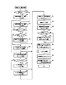
次に遊技機の動作について説明する。図4は、主基板31における遊技制御手段(例えば、CPU56等)が実行する特別図柄プロセス処理のプログラムの一例を示すフローチャートである。これらの処理は、主基板31の遊技制御手段が実行するメイン処理にて2ms毎に行われる割込処理内で実行される。CPU56は、特別図柄プロセス処理を行う際に、遊技盤6に設けられている始動入賞口14に遊技球が入賞したことを検出するための始動口スイッチがオンしていたら、すなわち遊技球が始動入賞口14に入賞する始動入賞が発生していたら(ステップS311)、始動口スイッチ通過処理(ステップS312)を行った後に、内部状態に応じて、ステップS300〜S308のうちのいずれかの処理を行う。
【0050】
なお、始動口スイッチ通過処理では、CPU56は、始動記憶数が最大値(例えば、4、等)に達しているかどうか確認し、始動記憶数が最大値に達していなければ、始動記憶数を1増やし、大当り判定用乱数等の各乱数の値を抽出し、それらを始動記憶数の値に対応した保存領域(始動記憶バッファ55c)に格納する処理が実行される。なお、乱数を抽出するとは、乱数を生成させるためのカウンタからカウント値を読み出して、読み出したカウント値を乱数値とすることである。
【0051】
特別図柄通常処理(ステップS300:表示結果事前決定手段):特別図柄10aの可変表示を開始できる状態になるのを待つ。CPU56は、特別図柄10aの可変表示が開始できる状態になると、始動記憶数を確認する。始動記憶数が0でなければ、特別図柄10aの可変表示の結果、大当りとするか否か決定する(表示結果事前決定手段)。そして、内部状態(特別図柄プロセスフラグ)をステップS301に移行するように更新する。
【0052】
特別図柄停止図柄設定処理(ステップS301:表示結果事前決定手段):可変表示後の特別図柄10aの停止図柄を決定する(表示結果事前決定手段)。そして、内部状態(特別図柄プロセスフラグ)をステップS302に移行するように更新する。
【0053】
変動パターン設定処理(ステップS302):特別図柄10aの可変表示の変動パターン(可変表示態様)を、変動パターン決定用乱数の値に応じて決定する。また、特別図柄プロセスタイマ55bをスタートさせる。このとき、演出制御基板80に対して、特別図柄10aの停止図柄と変動態様(変動パターン)を指令する情報とが送信される。そして、内部状態(特別図柄プロセスフラグ)をステップS303に移行するように更新する。
【0054】
特別図柄変動処理(ステップS303):所定時間(ステップS302の特別図柄プロセスタイマ55bで示された時間)が経過すると、内部状態(特別図柄プロセスフラグ)をステップS304に移行するように更新する。また、後述する準備コマンドを送信する。
【0055】
特別図柄停止処理(ステップS304):特別図柄表示部10において可変表示される特別図柄10aが停止されるように制御する。具体的には、特別図柄停止を示す演出制御コマンド(確定コマンド)が送信される状態に設定する。そして、停止後の特別図柄10aが大当り図柄となった場合には、内部状態(特別図柄プロセスフラグ)をステップS305に移行するように更新する。そうでない場合には、内部状態をステップS300に移行するように更新する。
【0056】
大入賞口開放前処理(ステップS305):大入賞口を開放する制御を開始する。具体的には、カウンタやフラグを初期化するとともに、ソレノイド21を駆動して開閉板20を開状態とすることで大入賞口を開放する。また、プロセスタイマによって大入賞口開放中処理の実行時間を設定し、大当り中フラグをセットする。そして、内部状態(特別図柄プロセスフラグ)をステップS306に移行するように更新する。
【0057】
大入賞口開放中処理(ステップS306):大入賞口ラウンド表示の演出制御コマンドを演出制御基板80に送出する制御や大入賞口の閉成条件の成立を確認する処理等を行う。最後の大入賞口の閉成条件が成立したら、内部状態をステップS307に移行するように更新する。
【0058】
特定領域有効時間処理(ステップS307):V入賞スイッチの通過の有無を監視して、大当り遊技状態継続条件の成立を確認する処理を行う。大当り遊技状態継続の条件が成立し、かつ、まだ残りラウンドがある場合には、内部状態をステップS305に移行するように更新する。また、所定の有効時間内に大当り遊技状態継続条件が成立しなかった場合、または、全てのラウンドを終えた場合には、内部状態をステップS308に移行するように更新する。
【0059】
大当り終了処理(ステップS308):大当り遊技状態が終了したことを遊技者に報知する表示制御を演出制御手段に行わせるための制御を行う。そして、内部状態をステップS300に移行するように更新する。
【0060】
図5は、特別図柄プロセス処理における第1実施形態の変動パターン設定処理(ステップS302)を示すフローチャートである。変動パターン設定処理において、CPU56は、確変状態中であるか否かを確認する(ステップS70)。確変状態中であるときには確変時変動パターン選択テーブル(図6(B)参照)を選択し(ステップS71)、確変状態でないときには、通常時変動パターン選択テーブル(図6(A)参照)を選択する(ステップS72)。
【0061】
次いで、大当りフラグがセットされている場合には(ステップS73)、確変大当りか否か判定し(ステップS74)、確変大当りの場合には選択された変動パターン選択テーブルの確変大当り時変動パターンテーブルを選択する(ステップS75)。つまり、現在の遊技状態が通常遊技状態の場合には、通常時変動パターン選択テーブル(図6(A))の確変大当り時変動パターンテーブルを選択し、現在の遊技状態が確変状態の場合には、確変時変動パターン選択テーブル(図6(B))の確変大当り時変動パターンテーブルを選択する。
【0062】
ステップS74で確変大当りではない場合(非確変大当り)には選択された変動パターン選択テーブルの非確変大当り時変動パターンテーブルを選択する(ステップS76)。つまり、現在の遊技状態が通常遊技状態の場合には、通常時変動パターン選択テーブル(図6(A))の非確変大当り時変動パターンテーブルを選択し、現在の遊技状態が確変状態の場合には、確変時変動パターン選択テーブル(図6(B))の非確変大当り時変動パターンテーブルを選択する。
【0063】
また、ステップS73で大当りフラグがセットされていない場合には、始動口スイッチ通過処理(ステップS312)で抽出したリーチ判定用乱数を読み出し、リーチするか否かを判定する(ステップS77)。つまり、抽出したリーチ判定用乱数がリーチ判定値と一致するか否かを判定する。リーチする場合には(ステップS78)、リーチ時変動パターンテーブルを選択する(ステップS79)。つまり、現在の遊技状態が通常遊技状態の場合には、通常時変動パターン選択テーブル(図6(A))のリーチ時変動パターンテーブルを選択し、現在の遊技状態が確変状態の場合には、リーチ時変動パターン選択テーブル(図6(B))の確変大当り時変動パターンテーブルを選択する。
【0064】
リーチしない場合には(ステップS78)、はずれ時変動パターンテーブルを選択する(ステップS80)。つまり、現在の遊技状態が通常遊技状態の場合には、通常時変動パターン選択テーブル(図6(A))のはずれ時変動パターンテーブルを選択し、現在の遊技状態が確変状態の場合には、確変時変動パターン選択テーブル(図6(B))のはずれ時変動パターンテーブルを選択する。
【0065】
図6には、変動パターン選択テーブルの一例が示されている。図6に示すように、変動パターン選択テーブルは、遊技機の状態が通常遊技状態のときに選択される通常時変動パターン選択テーブル(図6(A))と、確変状態のときに選択される確変時変動パターン選択テーブル(図6(B))と、を備えている。そして、変動パターン選択テーブルそれぞれには、表示結果事前決定手段(ステップS300)の決定結果に応じて選択される変動パターンテーブルが設けられている。
【0066】
なお、この実施の形態では、現在の遊技状態が通常遊技状態のときの当選時判定テーブルとして確変大当り時変動パターンテーブルと、非確変大当り時変動パターンテーブルと、を備え、現在の遊技状態が通常遊技状態のときの非当選時判定テーブルとして、リーチ時変動パターンテーブルと、はずれ時変動パターンテーブルと、を備えている。また、現在の遊技状態が確変状態のときの当選時判定テーブルとして確変大当り時変動パターンテーブルと、非確変大当り時変動パターンテーブルと、を備え、現在の遊技状態が確変状態のときの非当選時判定テーブルとして、リーチ時変動パターンテーブルと、はずれ時変動パターンテーブルと、を備えている。つまり、それぞれの遊技状態において、大当りとなるときに選択されるテーブルと、はずれとなるときに選択されるテーブルを備えている。
【0067】
そして、同一の変動パターンコマンド(EXT)によって指示される異なる複数の変動パターンにおいて、当選時判定テーブルにおける変動時間(可変表示時間)が短い変動パターンに決定される割合は、非当選時判定テーブルにおける変動時間が短い変動パターンに決定される割合よりも低くなるように変動パターンの決定に用いる判定データとしての通常時変動パターン選択テーブルおよび確変時変動パターン選択テーブルが構成されている。例えば、通常時変動パターン選択テーブルにおけるリーチAを実行する同一の変動パターンコマンドによって指示される変動パターンのうちリーチはずれとなる変動パターン3〜5は、確変大当りまたは非確変大当りとなる変動パターン11〜14よりも変動時間が短い変動パターンが選択される割合(例えば、リーチA’’よりもリーチAが選択される割合)が高くなるように構成されている。
【0068】
変動パターン設定処理において、変動パターンテーブルを選択すると(ステップS70〜ステップS80)、変動パターン決定用乱数カウンタをロードし(ステップS81)、選択された変動パターンテーブルに基づいて変動パターンを決定し(ステップS82:可変表示パターン事前決定手段)、決定された変動パターンに基づく変動時間を特別図柄プロセスタイマ55bに設定する(ステップS83)。
【0069】
次いで、CPU56は、決定された変動パターンが同一の変動パターンコマンド(EXT)によって指示される変動パターンであるか否か判定する(ステップS84)。つまり、決定された変動パターンが3〜8および11〜20のうちのいずれかに含まれるかを判定し、含まれる場合には変動パターンコマンドとして対応するEXTを選択する(ステップS85:可変表示データ選択手段)。つまり、上述したように、この実施の形態では、変動パターンと変動パターンコマンドはそれぞれ個々に対応して設けられていないため、例えば、変動パターン3〜5は同一の変動パターンコマンド(02H)によって指示される。ゆえに、同一の変動パターンコマンド(EXT)によって指示される異なる複数の変動パターンのうちいずれかが選択されたときには、異なる複数の変動パターンを指示する変動パターンコマンドを選択する可変表示データ選択手段(ステップS85)により、選択された変動パターンに基づく変動パターンコマンド(EXT)を特定する変動パターンコマンド特定テーブルに基づき変動パターンコマンドが選択される。変動パターンコマンド特定テーブルは、主基板31のROM54に記憶されている。
【0070】
次いで、CPU56は、決定された変動パターンに基づく変動パターンコマンドに応じたコマンド送信テーブルのアドレスをポインタにセットし(ステップS86)、サブルーチンであるコマンドセット処理を実行する(ステップS87)。そして、特別図柄プロセスタイマ55bをスタートさせ(ステップS88)、特別図柄プロセスフラグの値を特別図柄変動処理に対応した値に更新する(ステップS89)。
【0071】
コマンドセット処理を実行することによって演出制御コマンドが演出制御基板80に送信される。この実施の形態では、演出制御手段に送信されうる各演出制御コマンドはROM54のコマンド送信テーブルに格納されている。また、コマンドセット処理では、CPU56は、ポインタが示すROM54のアドレスに格納されている演出制御コマンドデータを、演出制御コマンドデータを出力するための出力ポートに設定するとともに、コマンドを送信することを示す演出制御INT信号を出力する。
【0072】
以上の処理によって、可変表示パターン事前決定手段(ステップS82)により同一の変動パターンコマンド(EXT)によって指示される変動時間が異なる複数の変動パターンの中の1つが選択されたときには、可変表示データ選択手段(ステップS85)により変動パターンコマンド特定テーブルに基づいて可変表示パターン事前決定手段によって決定された変動パターンコマンドに応じた変動パターンコマンド(EXT)が選択され、演出制御基板80に同一の変動パターンコマンド(EXT)が送信される。つまり、同一の変動パターンコマンド(EXT)によって指示される変動パターンに決定されたときには、同一の変動時間を指示する情報を含んだ変動パターンコマンド(EXT)が演出制御基板80に送信される。主基板31のCPU56は、変動パターンそれぞれに基づく変動時間を特別図柄プロセスタイマ55bに設定することで、変動パターンに基づく変動時間で特別図柄10aの可変表示が実行されるように制御し、特別図柄変動処理(ステップS303)にて特別図柄プロセスタイマ55bがタイムアウトしたか否かを判定し(可変表示時間判定手段)、プロセスタイマがタイムアウトしたことに基づいて、特別図柄停止処理(ステップS304)にて特別図柄10aを変動表示を停止させて表示結果を導出表示させる確定コマンドを送信する判定時確定信号送信手段を備えている。
【0073】
図7は、演出制御基板80に搭載される演出制御用CPU111が実行するメイン処理における表示制御プロセス処理を示すフローチャートである。この実施の形態では、表示制御プロセス処理は、2msごとに実行される割込処理で実行される。表示制御プロセス処理では、表示制御プロセスフラグの値に応じてステップS800〜S806のうちのいずれかの処理が行われる。各処理において、以下のような処理が実行される。
【0074】
変動パターンコマンド受信待ち処理(ステップS800):コマンド受信割込処理によって、演出制御コマンド(変動パターンコマンド)を受信したか否か確認する。具体的には、変動パターンコマンドが受信されたことを示すフラグ(変動パターン受信フラグ)がセットされたか否か確認する。変動パターン受信フラグは、演出制御用CPU111が実行するメイン処理における割込処理にて実行されるコマンド解析処理によって、変動パターン指定の演出制御コマンドが受信されたことが確認された場合にセットされる。
【0075】
飾り図柄演出設定処理(ステップS801):飾り図柄9a〜9cの停止図柄及び変動パターンを決定する。また、飾り図柄9a〜9cの変動パターンは、特別図柄10aの変動時間だけ、変動パターンコマンドが示す特別図柄10aの変動パターンに合致したものに決定される。また、受信した変動パターンコマンドに基づく変動時間を変動時間タイマ112aにセットする。
【0076】
図柄変動開始処理(ステップS802):特別図柄10aおよび飾り図柄9a〜9cの変動が開始されるように制御する。また、変動時間タイマ112aをスタートさせる。
【0077】
図柄変動中処理(ステップS803):変動パターンを構成する各変動状態(変動速度)の切替タイミングを制御するとともに、変動時間の終了を監視する。また、変動時間タイマ112aがタイムアウトまたは準備コマンドを受信したことに基づいて特別図柄10aおよび飾り図柄9a〜9cを停止させる処理に移行する。
【0078】
図柄停止待ち設定処理(ステップS804:導出表示手段):図柄停止を指示する演出制御コマンド(確定コマンド)を受信していたら、図柄の変動を停止し停止図柄(確定図柄)を表示する制御を行う。
【0079】
大当り表示処理(ステップS805):確定図柄の表示後、確変大当り表示または通常大当り表示の制御を行う。
【0080】
大当り遊技中処理(ステップS806):大当り遊技中の制御を行う。例えば、大入賞口開放前表示や大入賞口開放時表示の演出制御コマンドを受信したら、ラウンド数の表示制御等を行う。
【0081】
図8は、表示制御プロセス処理における第1実施形態の飾り図柄演出設定処理(ステップS801)を示すフローチャートである。飾り図柄演出設定処理において、演出制御用CPU111は、飾り図柄9a〜9cの停止図柄を決定する(ステップS801a)。このとき、変動パターンコマンドにもとづく特別図柄10aの変動態様に合致するように、飾り図柄9a〜9cの停止図柄を決定する。そして、飾り図柄9a〜9cの変動パターンを決定する(ステップS801b)。この例では、使用テーブルとして設定されている飾り図柄変動パターンテーブルに、受信した変動パターンコマンドに対応して設けられている変動パターンとする。従って、受信した変動パターンコマンドにもとづく特別図柄10aの変動パターンに対応して設けられている飾り図柄9a〜9cの変動パターンに決定される。そして、受信した変動パターンコマンドに基づく変動時間を変動時間タイマ112aにセットし(ステップS801c)、表示制御プロセスフラグの値を図柄変動開始処理(ステップS802)に対応した値に変更する(ステップS801d)。
【0082】
なお、ここで変動時間タイマ112aにセットされる変動時間は、可変表示パターン事前決定手段(ステップS82)によって決定された変動パターンに基づく変動時間ではなく、変動パターンコマンド(EXT00H〜09H)に基づく変動時間である。つまり、可変表示パターン事前決定手段(ステップS82)により同一の変動パターンコマンド(EXT)によって指示される異なる複数の変動パターンのうちいずれかが選択されたときには、異なる複数の変動パターンを指示する変動パターンコマンドを選択する可変表示データ選択手段(ステップS85)によって同一の変動パターンコマンド(EXT)が選択されるため、同一の変動パターンコマンド(EXT)によって指示される異なる複数の変動パターンのうちいずれの変動パターンが選択されても同一の変動パターンコマンド(EXT)が送信される。そして、変動パターンコマンド(EXT)には、変動パターンコマンド(EXT)に基づく1つの変動時間を指示する情報だけが送信されるため、演出制御用CPU111は、受信した変動パターンコマンド(EXT)に基づく変動時間を変動時間タイマ112aにセットする。
【0083】
図9は、演出制御プロセス処理における図柄変動中処理(ステップS803)を示すフローチャートである。図柄変動中処理において、演出制御用CPU111は、プロセスタイマがタイムアウトしたら(ステップS803a)、表示制御実行データの切替を行う(ステップS803b)。すなわち、プロセスデータ113aにおいて、次に設定されているプロセスタイマをスタートさせるとともに、その次に設定されている表示制御実行データの内容に従ってVDP100を制御する。従って、VDP100は、表示制御実行データの内容に応じて可変表示装置8の表示状態を制御する。
【0084】
そして、変動時間タイマ112aがタイムアウトしていたら(ステップS803c)、特別図柄10aの変動を停止させる演出制御コマンド(確定コマンド)の受信を監視するための監視タイマをスタートさせ(ステップS803e)、表示制御プロセスフラグの値を図柄停止待ち処理に対応した値にする(ステップS803f)。
【0085】
また、変動時間タイマ112aがタイムアウトしていない場合には、確定コマンドが送信されるまでの時間を示す(所定時間経過後に変動停止させることを示す)準備コマンドを受信しているか否かを判定し(ステップS803d)、準備コマンドを受信している場合には、ステップS803eの処理を実行し、プロセスフラグを図柄停止待ち処理に対応した値にする(ステップS803f)。
【0086】
準備コマンドを受信することによって、演出制御用CPU111は、特別図柄10aおよび飾り図柄9a〜9cの変動を停止させるための準備を行う。例えば、変動している特別図柄10aおよび飾り図柄9a〜9cの減速制御、等を行う。この場合には、実行しているプロセスデータ113aのアドレスを所定のアドレス(例えば、準備コマンドによって指定される残り時間に対応した位置)に変更するようにしてもよい。
【0087】
このように、この実施の形態では、変動時間タイマ112aがタイムアウトしていなくても準備コマンドを受信したことに基づいて可変表示を行っている特別図柄10aを停止させる確定コマンドの受信を監視する特別図柄停止待ち処理(ステップS804)を実行するため、可変表示パターン事前決定手段(ステップS82)により同一の変動パターンコマンド(EXT)によって指示される変動時間が異なる複数の変動パターンのうちいずれかが実行されることが決定されたときには、変動パターンコマンド(EXT)に基づく可変表示時間(変動時間)が経過していなくても判定時確定信号送信手段(ステップS83で特別図柄プロセスタイマ55bに設定された変動時間が、ステップS303でタイムアウトしたことに基づいて、ステップS304に移行制御し、ステップS304にて確定コマンドを送信する)によって送信された確定コマンドを受信したことに基づいて表示結果を導出表示させるように制御される。
【0088】
図10は、第1実施形態における変動パターンコマンドによって実行される変動パターンのタイミングチャートであり、(A)変動パターンコマンド(EXT)02H、(B)変動パターンコマンド(EXT)03H、(C)変動パターンコマンド(EXT)06H、(D)変動パターンコマンド(EXT)07H、(E)変動パターンコマンド(EXT)08H、である。図10に示すように、同一の変動パターンコマンドによって指定される異なる複数の変動パターンは同一の変動パターンデータ(プロセスデータ113a)で構成される。具体的には、変動パターン3〜5は、同一のプロセスデータ113aで構成され、変動パターンそれぞれに対応して設けられている変動時間で確定コマンドを受信することにより表示結果を導出表示させる。
【0089】
異なる複数の変動パターンを含んだ変動パターンコマンドの一例として、変動パターンコマンド(EXT)02Hには、変動パターンコマンド(EXT)02Hによって指示される変動パターンのうち最も変動時間が長い変動パターン5に基づく変動時間(40秒)を指示する情報が含まれている。演出制御用CPU111は、変動パターンコマンド(EXT)02Hを受信すると、変動パターンコマンド(EXT)02Hに基づく変動時間40秒の変動を開始させる。主基板31のCPU56は、可変表示パターン事前決定手段(ステップS82)によって決定された変動パターンに基づく変動時間を特別図柄プロセスタイマ55bに設定し、特別図柄プロセスタイマ55bがタイムアウトしたことに基づいて、特別図柄10aの変動を停止させて表示結果事前決定手段(ステップS301)によって決定された表示結果を導出表示させる確定コマンドを演出制御基板80に送信する。例えば、可変表示パターン事前決定手段により変動パターン3に決定されたときには、変動時間18秒で、つまり、A1のタイミングで確定コマンドを送信し、演出制御用CPU111の導出表示手段(ステップS804)は、確定コマンドを受信したことに基づいて特別図柄表示部10および飾り図柄表示部9に表示結果を導出表示させる。
【0090】
なお、この実施の形態では、変動パターンコマンドに基づく変動時間で表示結果を導出表示しない場合には、確定コマンドを受信する前に特別図柄10aを停止させる残りの変動時間を示す(確定コマンドを受信するまでの時間を示す)準備コマンドが主基板31から送信される。演出制御用CPU111は、準備コマンドを受信することにより、変動時間タイマ112aがタイムアウトしていなくても特別図柄停止待ち処理(ステップS804)に移行制御する。
【0091】
また、この実施の形態で用いられる準備コマンドはすべての変動パターンコマンド(EXT02H,03H,06H〜08H)に共通して用いられる1つのコマンドであるため、コマンド数の増加を抑えることができる。例えば、変動パターンコマンド02Hで、変動パターン3のときに送信される準備コマンドと、変動パターン4のときに送信される準備コマンドと、変動パターンコマンド08Hで変動パターン19のときに送信される準備コマンドと、はすべて共通のコマンドである。
【0092】
また、CPU56は、変動開始を指示する変動パターンコマンドとほぼ同時(例えば、メインの割込処理で同一の割込処理内)に表示結果事前決定手段(ステップS301)によって決定された表示結果を指定するコマンド(特別図柄指定コマンド)を送信する。そして、演出制御用CPU111は、準備コマンドを受信したことに基づいて特別図柄指定コマンドによって指定された特別図柄10aを準備し、確定コマンドを受信したことに基づいて、変動表示を行っている特別図柄10aと差し替える処理を実行する(識別情報差し替え手段)。また、演出制御用CPU111は、特別図柄指定コマンドを受信したことに基づいて、ステップS801a(図8参照)にて飾り図柄表示部9における飾り図柄9a〜9cの停止図柄を決定する。そして、準備コマンドを受信したことに基づいて、ステップS801aにて決定された飾り図柄9a〜9cの停止図柄を準備し、確定コマンドを受信したことに基づいて特別図柄10aおよび飾り図柄9a〜9cの変動(可変表示)を停止させるとともに、変動表示を行っている特別図柄10aを表示結果事前決定手段(ステップS301)にて決定された表示結果に差し替える処理と、変動表示を行っている飾り図柄(9a〜9cのいずれか又は全て)をステップS801aにて決定された飾り図柄9a〜9cの停止図柄に差し替える処理を実行する(識別情報差し替え手段)。
【0093】
このように、本実施形態においては、同一の変動パターンコマンド(EXT)によって指示される異なる複数の変動パターンは、同一のプロセスデータ113aによって構成され、表示結果を導出表示させる変動時間を異ならせることにより異なる複数の変動パターンを実行することが可能となっている。
【0094】
なお、同一の変動パターンコマンド(EXT)によって指示される異なる複数の変動パターンのうち大当りとなる変動パターンコマンド06H〜08Hについては、最も変動時間が長くなる変動パターンにて、表示結果事前決定手段(ステップS301)によって決定された特定表示結果(大当り図柄)と同一または異なる表示結果(大当り図柄)を一旦導出したあとに表示結果事前決定手段(ステップS301)によって決定された特定表示結果(大当り図柄)を導出表示させる再抽選演出を実行するようにしてもよい。以下、再抽選演出を実行する第2実施形態について説明する。
【0095】
(第2実施形態)
図11は、第2実施形態で用いられる変動パターン(可変表示パターン)の一例を示す説明図である。図11において、「EXT」とは、2バイト構成の演出制御コマンドにおける2バイト目のEXTデータを示す。この実施の形態では、特別図柄10aの各変動パターンと演出制御コマンドとは1対1に対応付けられていない。具体的には、変動パターン3〜5、6〜8、11〜14、15〜18、19および20は、それぞれ同一の変動パターンコマンド(EXT)となっており、変動パターンそれぞれには演出制御コマンドが設けられていない。つまり、同一のEXTの変動パターンでは、同一の変動時間を指示する情報が含まれる。
【0096】
このように、同一の可変表示データとしての変動パターンコマンド(EXT)には、特定可変表示パターンとして上記した複数の変動パターンを含み、変動パターンコマンド(可変表示パターンコマンド)によって指定される可変表示時間(変動時間)とは異なる複数のタイミングで表示結果を導出表示させることにより複数の変動パターンとなる。つまり、同一の変動パターンコマンド(EXT)によって指定される変動パターンには異なる変動時間(可変表示時間)が予め定められている。具体的には、変動パターン3〜5は、同一の変動パターンコマンド02によって変動時間40秒が指定されている。そして、変動時間を18秒とすることで変動パターン3となり、変動時間を28秒とすることで変動パターン4となり、変動時間を40秒とすることで変動パターン5とすることが可能である。
【0097】
なお、上述したように、主基板31から送信される変動パターンコマンド(EXT)は、変動パターンそれぞれに対応して設けられていない。そのため、変動パターンコマンドを受信したときに演出制御用CPU111によって変動時間タイマ112aにセットされる変動時間は、変動パターンコマンド(EXT)に基づく変動時間であり、同一の変動パターンコマンド(EXT)によって指示される変動パターンにおいては、最も変動時間が長い変動パターンに基づく変動時間が変動時間タイマ112aにセットされる。
【0098】
また、この実施の形態では、同一の変動パターンコマンド(EXT)によって指定される変動パターンのうち大当りとなる変動パターンコマンド06H〜08Hでは、上記した再抽選演出が実行される。つまり、変動パターン14、18および20は、再抽選演出を行う再抽選可変表示パターンである。
【0099】
また、「通常変動」とは、リーチ態様を伴わない変動パターンである。更に、この実施の形態では、短縮変動パターンが用いられる。短縮変動パターンは、特別図柄10aの変動時間が例えば1.0秒という極めて短い変動パターンである。
【0100】
また、この実施の形態では、高確率時(確変中)でも低確率時(非確変中=通常状態)でも変動パターン1〜9の変動パターンが用いられるが、高確率時には変動パターン1〜9のそれぞれの変動時間を短くするようにしてもよい。また、高確率時に用いられる変動パターン群(使用されうる複数の変動パターン)と、低確率時に用いられる変動パターン群と、を別にしてもよい。
【0101】
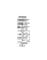
図12は、特別図柄プロセス処理における第2実施形態の変動パターン設定処理(ステップS302)を示すフローチャートである。変動パターン設定処理において、CPU56は、確変状態中であるか否かを確認する(ステップSA70)。確変状態中であるときには確変時変動パターン選択テーブル(図6(B)参照)を選択し(ステップSA71)、確変状態でないときには、通常時変動パターン選択テーブル(図6(A)参照)を選択する(ステップSA72)。
【0102】
次いで、大当りフラグがセットされている場合には(ステップSA73)、確変大当りか否か判定し(ステップSA74)、確変大当りの場合には選択された変動パターン選択テーブルの確変大当り時変動パターンテーブルを選択する(ステップSA75)。ステップSA74で確変大当りではない場合(非確変大当り)には選択された変動パターン選択テーブルの非確変大当り時変動パターンテーブルを選択する(ステップSA76)。また、ステップSA73で大当りフラグがセットされていない場合には、始動口スイッチ通過処理(ステップS312)で抽出したリーチ判定用乱数を読み出し、リーチするか否かを判定する(ステップSA77)。つまり、抽出したリーチ判定用乱数がリーチ判定値と一致するか否かを判定する。リーチする場合には(ステップSA78)、リーチ時変動パターンテーブルを選択し(ステップSA79)、リーチしない場合には(ステップSA78)、はずれ時変動パターンテーブルを選択する(ステップSA80)。
【0103】
この実施の形態においても、図6に示す変動パターン選択テーブルを備えている。また、この実施の形態では、予め定められた複数種類の特定表示結果(大当り図柄)として大当り遊技状態終了後に大当り遊技状態とは異なる遊技状態であって遊技者にとって有利な特別遊技状態(例えば、確変状態、等)となる第1特定表示結果としての確変図柄と、大当り遊技状態終了後に特別遊技状態および大当り遊技状態とは異なる通常遊技状態となる第2特定表示結果としての非確変図柄と、が設定されている。
【0104】
また、上記した表示結果事前決定手段(ステップS301)により確変図柄とすることが決定されたときに後述する可変表示パターン事前決定手段(ステップSA82)によって再抽選可変表示パターンとするか否かの決定に用いる第1特定判定テーブルとしての確変大当り時変動パターンテーブルと、表示結果事前決定手段(ステップS301)により非確変図柄とすることが決定されたときに後述する可変表示パターン事前決定手段(ステップSA82)によって再抽選可変表示パターンとするか否かの決定に用いる第2特定判定テーブルとしての非確変大当り時変動パターンテーブルと、を備えている。
【0105】
そして、同一の変動パターンコマンド(EXT)によって指示される異なる複数の変動パターンにおいて、確変大当り時変動パターンテーブルにおける再抽選可変表示パターンを行う旨の決定がなされる割合は非確変大当り時変動パターンテーブルにおける割合よりも高くなるように再抽選可変表示パターンを行う決定に用いる判定データとしての通常時変動パターン選択テーブルおよび確変時変動パターン選択テーブルが構成されている。例えば、通常時変動パターン選択テーブルにおけるリーチAを実行する同一の変動パターンコマンドによって指定される変動パターンのうち再抽選可変表示パターンとしての変動パターン14を確変大当りとなるときに実行する割合は、非確変時大当りとなるときに実行される割合よりも高くなるように構成されている。
【0106】
変動パターン設定処理において、変動パターンテーブルを選択すると(ステップSA70〜SA80)、変動パターン決定用乱数カウンタをロードし(ステップSA81)、選択された変動パターンテーブルに基づいて変動パターンを決定し(ステップSA82:可変表示パターン事前決定手段)、決定された変動パターンに基づく変動時間を特別図柄プロセスタイマ55bに設定する(ステップSA83)。
【0107】
次いで、CPU56は、決定された変動パターンが同一の変動パターンコマンド(EXT)によって指示される変動パターンのうち変動パターンコマンドに基づく変動時間とは異なる変動時間が設定されている変動パターンであるか否かを判定する(ステップSA84)。つまり、変動パターン3,4,6,7,11〜13,15〜17,19のいずれかに決定された否か判定する。これらのいずれかに決定された場合には、短縮コマンドに応じたコマンド送信テーブルのアドレスをポインタにセットする(ステップSA85)。短縮コマンドとは、変動パターンコマンドに基づく変動時間とは異なる変動時間(この実施の形態では、変動パターンコマンドに基づく変動時間よりも短い変動時間)で変動が行われることを示すコマンドであり、変動時間を指定する情報は含まれない。そのため、演出制御用CPU111は、変動時間が短縮されることのみを把握することが可能となるが、短縮された変動時間を特定することはできない。
【0108】
次いで、CPU56は、決定された変動パターンが同一の変動パターンコマンド(EXT)によって指示される変動パターンであるか否か判定する(ステップSA86)。つまり、決定された変動パターンが3〜8および11〜20のうちのいずれかに含まれるかを判定し、含まれる場合には変動パターンコマンドとして対応するEXTを選択する(ステップSA87:可変表示データ選択手段)。つまり、上述したように、この実施の形態では、変動パターンと変動パターンコマンドはそれぞれ個々に対応して設けられていないため、例えば、変動パターン3〜5は同一の変動パターンコマンド(02H)によって指示される。ゆえに、同一の変動パターンコマンド(EXT)によって指示される異なる複数の変動パターンのうちいずれかが選択されたときには、異なる複数の変動パターンを指示する変動パターンコマンドを選択する可変表示データ選択手段(ステップSA87)を備えている。
【0109】
次いで、CPU56は、決定された変動パターンに基づく変動パターンコマンドに応じたコマンド送信テーブルのアドレスをポインタにセットし(ステップSA88)、サブルーチンであるコマンドセット処理を実行する(ステップSA89)。そして、特別図柄プロセスタイマ55bをスタートさせ(ステップS90)、特別図柄プロセスフラグの値を特別図柄変動処理に対応した値に更新する(ステップS91)。
【0110】
以上の処理によって、可変表示パターン事前決定手段(ステップSA82)によって変動パターンコマンド(EXT)に基づく変動時間とは異なる変動時間で変動が行われる変動パターンが選択されたときには、演出制御基板80に短縮コマンドが送信される。
【0111】
図13は、表示制御プロセス処理における第2実施形態の飾り図柄演出設定処理(ステップS801)を示すフローチャートである。飾り図柄演出設定処理において、演出制御用CPU111は、飾り図柄9a〜9cの停止図柄を決定する(ステップSA801a)。このとき、変動パターンコマンドにもとづく特別図柄10aの変動態様に合致するように、飾り図柄9a〜9cの停止図柄を決定する。そして、飾り図柄9a〜9cの変動パターンを決定する(ステップSA801b)。この例では、使用テーブルとして設定されている飾り図柄変動パターンテーブルに、受信した変動パターンコマンドに対応して設けられている変動パターンとする。従って、受信した変動パターンコマンドにもとづく特別図柄10aの変動パターンに対応して設けられている飾り図柄9a〜9cの変動パターンに決定される。そして、受信した変動パターンコマンドに基づく変動時間を変動時間タイマ112aにセットし(ステップSA801c)、受信した変動パターンコマンド(EXT)が02H,03Hおよび06H〜08Hのうちのいずれかであるか判定し(ステップSA801d)、これらいずれかの変動パターンである場合には短縮コマンドを受信したか否かを判定する(ステップSA801e)。
【0112】
この実施の形態では、同一の変動パターンコマンド(EXT)によって指示される変動パターンには、再抽選演出を実行する再抽選可変表示パターンが含まれている。そして、変動パターンコマンドに基づく変動時間で図柄の変動が行われない場合、つまり、再抽選演出を実行しない場合には、短縮コマンドを送信する。ゆえに、短縮コマンドを受信していない場合には、再抽選演出が実行される。再抽選演出では、表示結果事前決定手段(ステップS301)で決定された特定表示結果と同一または異なる特定表示結果を一旦導出させる。そのため、短縮コマンドを受信していない場合には、演出制御用CPU111は、一旦導出させる図柄、つまり、飾り図柄9a〜9cの仮停止図柄を決定する(ステップSA801f)。そして、表示制御プロセスフラグの値を図柄変動開始処理(ステップS802)に対応した値に変更する(ステップS801g)。
【0113】
なお、この実施の形態においても、変動時間タイマ112aにセットされる変動時間は可変表示パターン事前決定手段(ステップSA82)によって決定された変動パターンに基づく変動時間ではなく、変動パターンコマンド(EXT00H〜09H)に基づく変動時間である。
【0114】
図14は、第2実施形態における変動パターンコマンドによって実行される変動パターンのタイミングチャートであり、(A)変動パターンコマンド(EXT)02H、(B)変動パターンコマンド(EXT)03H、(C)変動パターンコマンド(EXT)06H、(D)変動パターンコマンド(EXT)07H、(E)変動パターンコマンド(EXT)08H、である。図14に示すように、同一の変動パターンコマンドによって指定される異なる複数の変動パターンは同一の変動パターンデータ(プロセスデータ113a)で構成される。具体的には、変動パターン3〜5は、同一のプロセスデータ113aで構成され、変動パターンそれぞれに対応して設けられている変動時間で確定コマンドを受信することにより表示結果を導出表示させる。
【0115】
上述したように、異なる複数の変動パターンを含んだ変動パターンコマンドのうち大当りとなる変動パターンコマンド(EXT)06H〜08Hには、再抽選演出を行う再抽選可変表示パターンが含まれている。つまり、変動パターンコマンド(EXT)に基づく変動時間で図柄の変動が行われるときに再抽選演出が実行される。
【0116】
異なる複数の変動パターンを含んだ変動パターンコマンド(EXT)のうち大当りとなる変動パターンコマンド(EXT)の一例として変動パターンコマンド(EXT)06Hには、変動パターンコマンドによって指示される変動パターンのうち最も変動時間が長い変動パターン14に基づく変動時間(56秒)を指示する情報が含まれている。演出制御用CPU111は、変動パターンコマンド(EXT)06Hを受信すると、変動パターンコマンド(EXT)に基づく変動時間56秒の変動を開始させる。主基板31のCPU56は、可変表示パターン事前決定手段(ステップSA82)によって決定された変動パターンに基づく変動時間を特別図柄プロセスタイマ55bに設定し、特別図柄プロセスタイマ55bがタイムアウトしたことに基づいて、特別図柄10aの変動を停止させて表示結果事前決定手段(ステップS301)によって決定された表示結果を導出表示させる確定コマンドを演出制御基板80に送信する。そして、演出制御手段の導出表示手段(ステップS804)は、確定コマンドを受信したことに基づいて特別図柄表示部10および飾り図柄表示部9に表示結果を導出表示させる。
【0117】
なお、上述したように第2実施形態では、変動パターンコマンドに基づく変動時間で図柄の変動が行われない場合には、主基板31のCPU56は、短縮コマンドを送信する。なお、上述したように短縮コマンドは、変動パターンコマンドに基づく変動時間よりも短い変動時間で図柄の変動が行われる旨を示すものであり、変動時間を特定する情報は含まれない。つまり、変動パターンコマンド(EXT)06Hにおいて、変動パターン11〜13のうちいずれかの変動パターンを行うことが決定されると主基板31のCPU56は短縮コマンドを送信する。しかし、演出制御用CPU111は、短縮コマンドを受信しても、変動パターン11〜13のうちいずれかの変動パターンが実行されることを認識することができるだけであり、確定コマンドが送信される変動時間(例えば、変動パターン11で確定コマンドが送信されるC1のタイミング:変動時間20秒)を特定することはできない。つまり、短縮コマンドは、再抽選演出を行うか否かを指定するコマンドである。
【0118】
更に、この実施の形態では、変動パターンコマンドに基づく変動時間で表示結果を導出表示しない場合には、確定コマンドを受信する前に特別図柄10aを停止させる残りの変動時間を示す(確定コマンドを受信するまでの時間を示す)準備コマンドが主基板31から送信される。演出制御用CPU111は、準備コマンドを受信することにより、変動時間タイマ112aがタイムアウトしていなくても特別図柄停止待ち処理(ステップS804)に移行制御する。
【0119】
また、異なる複数の変動パターンを含んだ変動パターンコマンド(EXT)のうち大当りとなる変動パターンコマンド(EXT)において、短縮コマンドを受信していない場合には、演出制御用CPU111は、飾り図柄9a〜9cの仮停止図柄を決定する。変動パターンコマンド(EXT)06Hの場合には、C3のタイミング、つまり、変動時間46秒が経過したときに、ステップSA801fにて決定された飾り図柄9a〜9cの仮停止図柄を一旦導出する。そして、飾り図柄9a〜9cを再び変動させ、特別図柄プロセスタイマ55bがタイムアウトしたことに基づいて送信される確定コマンドを受信したことに基づいて特別図柄表示部10に表示結果事前決定手段(ステップS301)にて決定された特定表示結果を導出表示するとともに、飾り図柄表示部9にステップSA801aにて決定された特定表示結果を導出表示させる。
【0120】
なお、このとき導出される仮停止図柄は表示結果事前決定手段(ステップS301)にて決定された大当り図柄(特定表示結果)と同一または異なる大当り図柄が表示される。つまり、この実施の形態では、大当り遊技状態終了後に大当り遊技状態とは異なる遊技状態であって遊技者にとって有利な確変状態に制御される確変図柄と、大当り終了後に大当り遊技状態および確変状態とは異なる通常遊技状態に制御される非確変図柄と、を備えており、遊技者は、確変図柄が表示されることを期待しつつ遊技を行う。そこで、確変図柄で大当り遊技状態となるときに、仮停止図柄として非確変図柄を表示させ、確定コマンドを受信したときに確変図柄を表示させることにより、遊技者の興趣を向上させることができる。
【0121】
また、この実施の形態で用いられる準備コマンドはすべての変動パターンコマンド(EXT02H,03H,06H〜08H)に共通して用いられる1つのコマンドであるため、コマンド数の増加を抑えることができる。例えば、変動パターンコマンド02Hで、変動パターン3のときに送信される準備コマンドと、変動パターン4のときに送信される準備コマンドと、変動パターンコマンド08Hで変動パターン19のときに送信される準備コマンドと、はすべて共通のコマンドである。
【0122】
このように、本実施形態においては、同一の変動パターンコマンド(EXT)によって指示される異なる複数の変動パターンは、同一のプロセスデータ113aによって構成され、表示結果を導出表示させる変動時間を異ならせることにより異なる複数の変動パターンを実行することが可能となっている。
【0123】
また、第2実施形態では、異なる複数の変動パターンを含んだ変動パターンコマンド(EXT)のうち大当りとなる変動パターンコマンド(EXT)すべてに再抽選可変表示パターンが含まれている。そのため、異なる複数の変動パターンを含んだ変動パターンコマンド(EXT)のうち大当りとなる変動パターンコマンド(EXT)の再抽選可変表示パターンとした場合には、ステップSA801fで決定された仮停止図柄が一旦導出された後、確定コマンドを受信したことに基づいてステップSA801aで決定された確定図柄が導出表示される。しかし、異なる複数の変動パターンを含んだ変動パターンコマンド(EXT)のうち大当りとなる変動パターンコマンド(EXT)の再抽選可変表示パターンとしない場合には、再抽選可変表示パターンの一旦導出させるタイミングよりも前でステップSA801aで決定された確定図柄が導出表示されるように制御するため、再抽選パターンとするか否かを事前に演出制御用CPU111に伝えておく必要がある。ゆえに、この実施の形態では、再抽選可変表示パターンとしない場合には短縮コマンドが主基板31から演出制御基板80に送信されることで演出制御用CPU111に認識させているが、異なる複数の変動パターンを含んだ変動パターンコマンド(EXT)のうち再抽選可変表示パターンを含まない変動パターンコマンド(例えば、EXT02H,03H)が選択された場合には、短縮コマンドを送信しない構成としてもよい。この場合には、主基板31から演出制御基板80に可変表示パターン事前決定手段(例えば、ステップSA82)によって決定された変動パターンに基づく変動時間で可変表示装置8の特別図柄10aの変動を停止させる確定コマンドを送信することにより、演出制御用CPU111は、変動パターンに基づく変動時間で可変表示装置8の特別図柄10aの変動を停止させる制御を行う。
【0124】
なお、上述した第1実施形態および第2実施形態では、主基板31から演出制御基板80に準備コマンドを送信することにより、変動を停止させるタイミングを認識させるようにしているが、準備コマンドを送信しないようにしてもよい。この実施の形態では、準備コマンドを演出制御基板80に送信することで、演出制御用CPU111が特定の可変表示データに基づく可変表示時間が経過していなくても停止タイミングを予め(準備コマンドを受信した時点で)判断できるため、遊技者に、より違和感を感じさせることなく停止図柄の導出表示を実現することができる。
【0125】
【発明の効果】
以上のように、請求項1記載の発明では、複数の可変表示パターンを含む可変表示パターンに対し、確定信号の送信タイミングによって複数の演出に用いることが可能となるため、データ量および信号種類の軽減を図ることができる。
【0126】
請求項2記載の発明では、複数の可変表示パターンを含む可変表示パターンに対し、確定信号の送信タイミングによって複数の演出に用いることが可能となるため、データ量および信号種類の軽減を図ることができる。
【0127】
請求項3記載の発明では、表示結果事前決定手段により第1特定表示結果を表示することが決定されたときには再抽選演出が実行されやすくなり、第1特定表示結果を表示する前には再抽選演出を実行することにより、遊技者に遊技に対する興趣を長引かせることができ、興趣を向上させることができる。
【0128】
請求項4記載の発明では、表示結果事前決定手段により特定表示結果を表示することが決定されたときには、可変表示時間が長くなるような可変表示パターンが選択されやすくなり、可変表示時間が長くなることにより、遊技者に遊技に対する興趣を長引かせることができ、興趣を向上させることができる。
【0129】
請求項5記載の発明では、表示制御手段は、識別情報信号を受信したことによって当該識別情報信号によって指定される識別情報を準備し、確定信号に基づいて可変表示中の識別情報と差し替えることにより、予め定められた表示結果を確定表示結果として表示することが可能となる。
【図面の簡単な説明】
【図1】本実施形態に係る弾球遊技機を正面からみた正面図である。
【図2】本実施形態に係る弾球遊技機1の回路構成の概要を表したブロック図である。
【図3】第1実施形態の変動パターンの一例を示す説明図である。
【図4】特別図柄プロセス処理を示すフローチャートである。
【図5】第1実施形態の変動パターン設定処理を示すフローチャートである。
【図6】変動パターン選択テーブルの一例を示す説明図である。
【図7】表示制御プロセス処理を示すフローチャートである。
【図8】第1実施形態の飾り図柄演出設定処理を示すフローチャートである。
【図9】図柄変動中処理を示すフローチャートである。
【図10】第1実施形態のタイミングチャートを示す説明図である。
【図11】第2実施形態の変動パターンの一例を示す説明図である。
【図12】第2実施形態の変動パターン設定処理を示すフローチャートである。
【図13】第2実施形態の飾り図柄演出設定処理を示すフローチャートである。
【図14】第2実施形態のタイミングチャートを示す説明図である。
【符号の説明】
1 弾球遊技機
8 可変表示装置
9 飾り図柄表示部
10 特別図柄表示部
14 始動入賞口
15 可変入賞球装置
31 主基板
56 CPU
80 演出制御基板
111 演出制御用CPU[0001]
TECHNICAL FIELD OF THE INVENTION
The present invention includes a variable display device that variably displays a plurality of types of identification information each of which can be identified based on establishment of a predetermined start condition and derives and displays a display result, wherein the display result of the identification information is predetermined. The present invention relates to a gaming machine that controls a specific gaming state advantageous to a player when a specific display result is obtained.
[0002]
[Prior art]
Conventionally, in a gaming machine equipped with a variable display device that performs variable display of a plurality of types of identification information each of which can be identified based on establishment of a predetermined starting condition and derives and displays a display result, for example, in a ball game machine, Before the start of the variable display of the variable display device, the game control means includes a variable pattern command including a variable display time and a variable mode (with or without reach, with or without re-variation, etc.) and a display control capable of specifying a stop symbol. And the command to the display control means, and after the display control means having received these commands performs symbol replacement control, when the variable display time ends, the game control means causes the display control command to indicate that all symbols have been stopped. In some cases, the display control means causes the display control means to display a fixed symbol (for example, see Patent Document 1).
[0003]
[Patent Document 1]
Japanese Patent Application Laid-Open No. 2001-17677 (pages 9-11, FIG. 21)
[0004]
[Problems to be solved by the invention]
In the gaming machine having the above-described configuration, it is possible to execute a plurality of effects by changing a display control command capable of specifying a stop symbol for one variation pattern. The number of variation patterns to be transmitted has been reduced, and it has become possible to reduce the burden of control on the symbol display of the game control means. Since there are two types, that is, the case where none is provided, the variation pattern command is not significantly reduced, and the amount of data in the game control means cannot be significantly reduced. Further, the display control means also needs to have data for each of the fluctuation patterns transmitted from the game control means, so that the data amount has increased. The present invention has been made in view of the above-described circumstances, and an object of the present invention is to provide a gaming machine that can be used for a plurality of effects by changing a variable display time of one variation pattern. .
[0005]
[Means for Solving the Problems]
In order to achieve the above object, in the invention according to
[0006]
Further, in the invention according to
[0007]
Further, in the invention according to
[0008]
Further, in the invention according to
[0009]
In the invention according to
[0010]
BEST MODE FOR CARRYING OUT THE INVENTION
Hereinafter, an embodiment of the present invention will be described with reference to the drawings. First, the overall configuration of a
[0011]
The
[0012]
As shown in FIG. 1, the
[0013]
In the vicinity of the center of the
[0014]
It should be noted that the
[0015]
The specific display result includes a first specific display result (probable variable design) and a second specific display result (non-probable variable design) other than the first specific display result, and the
[0016]
In addition, by controlling the special game state to the time saving state, the state may be made more advantageous for the player. In the time saving state, the special
[0017]
In addition, the special game state is not limited to the above, and the game control that is advantageous to the player may be set to the special game state. Hereinafter, the game control will be described by dividing into those that are not directly related to the big hit (except during the specific game state) and those that are directly related to the big hit (during the specific game state). That is, the special game state added to the specific game state may be a special game state different from the specific game state, or may be a special game state including the specific game state. First, as the game control not directly related to the big hit, time reduction (time saving) control or probability variation (probable change) control for the special symbol 10a to the ordinary symbol, electric power (for example, the variable winning ball device 15) Control of the opening period of the special symbol or the addition control of the starting passage area for the special symbol or the ordinary symbol (for example, the winning prize holes 29, 30, 33, 39 installed on the
[0018]
On the upper part of the
[0019]
In this embodiment, the number of effective start winnings is four, but the number is not limited to four. For example, the number of effective start winnings may be set to 30. In this case, the start memory display area may be configured to display the number of start memories for 30 times, and only a predetermined number (for example, 5) of the 30 times of start memories may be displayed. Is also good.
[0020]
Further, in the
[0021]
Below the
[0022]
An opening /
[0023]
When a game ball is won at the gate 32 and detected by the gate switch, a predetermined random number value is extracted unless the normal symbol starting memory, which is the initial memory of the
[0024]
In this embodiment, variable display of a normal symbol is performed by alternately lighting left and right lamps (designs become visible at the time of lighting) marked with ○ and ×, and the variable display is performed for a predetermined time (for example, 29 seconds). .2 seconds). Then, if the left lamp marked with a circle is turned on at the end of the variable display, it is a hit. Whether or not to win is determined by whether or not the value of the random number extracted when the gaming ball has won the gate 32 matches a predetermined hit determination value. When the display result of the variable display on the ordinary
[0025]
Further, in the probable change state as the special game state, the probability that the stop symbol of the special symbol 10a in the special
[0026]
At the left and right sides of the
[0027]
Next, the reach state will be described. The reach state in the present embodiment means that when the stopped symbols form a part of the big hit symbol, the symbols that have not been stopped are displayed in a variable manner (variable display), and all or one of them is displayed. This is a state in which the symbol of the part is synchronously changed and displayed while composing all or a part of the big hit symbol.
[0028]
In the present embodiment, an effective line that becomes a big hit when the predetermined symbol stops is determined in the decorative symbol display unit 9 as a plurality of predetermined display areas, and a part of the effective line is displayed. A state in which the variable display is performed in the display area on the active line that has not been stopped when the predetermined symbol is stopped in the area (for example, left, right, and left of the left, middle, and right display areas) Is a part of the big hit symbol (for example, “7”) is displayed in a stopped state, and the right display area is still in a variable display state). A state in which all or part of the symbols are variably displayed while forming all or part of the big hit symbol (for example, variably displayed in all of the left, middle, and right display areas, and is always displayed. A state in which the same symbols are aligned Refers to the state) variable display is being carried out.
[0029]
Since the special
[0030]
At the time of the reach, an unusual effect may be performed by a lamp or sound. This production is called reach production. In addition, at the time of the reach, a character (an effect display imitating a person or the like, which is different from the design) may be displayed, or the display mode of the background may be changed. This change in the display of the character and the display of the background is called reach effect display.
[0031]
A game ball fired from the hit ball firing device enters the
[0032]
The variable display of the special symbol 10a on the special
[0033]
When the special symbol 10a in the special
[0034]
FIG. 2 is a block diagram illustrating an outline of a circuit configuration of the
[0035]
Although not shown in FIG. 2, a switch circuit for giving signals from the gate switch, starting port switch, V winning switch, count switch, full switch, count switch short circuit signal and clear switch to the
[0036]
A part or all of the RAM (may be a CPU built-in RAM) 55 is a backup RAM backed up by a backup power supply created on a power supply board. That is, even if the power supply to the gaming machine is stopped, a part or all of the content of the RAM 55 is stored for a predetermined period.
[0037]
The RAM 55 mounted on the main board 31 has a big hit flag memory 55a for storing a big hit flag, which will be described later, and a change (variable display) of the special symbol 10a in the special
[0038]
Further, based on a command from a game control means (for example, CPU 56) provided on the main board 31, an effect control CPU 111 as an effect control means provided on the
[0039]
In this embodiment, the display control means 111a included in the effect control means (for example, the effect control CPU 111) mounted on the
[0040]
The
[0041]
The RAM 112 according to the present embodiment controls the special
[0042]
The ROM 113 according to the present embodiment is referred to when the variation pattern command is transmitted from the main board 31 and stores data for executing the variable display of the decorative symbols 9a to 9c on the decorative symbol display unit 9. Process data 113a. That is, when receiving the variation pattern command output from the main board 31, the display control means 111a of the effect control CPU 111 refers to the process data 113a based on the received variation pattern command stored in the ROM 113, and refers to the referenced process data 113a. Display control of the decorative symbol display unit 9 is controlled according to 113a.
[0043]
The effect control CPU 111 controls display of the decorative symbol display unit 9 using the LCD via the
[0044]
FIG. 3 is an explanatory diagram illustrating an example of a variation pattern (variable display pattern) used in the first embodiment. In FIG. 3, “EXT” indicates EXT data of the second byte in the effect control command having a 2-byte configuration. In this embodiment, each variation pattern of the special symbol 10a is not associated with the effect control command on a one-to-one basis. More specifically, the
[0045]
As described above, the variation pattern command (EXT) as the same variable display data signal includes the plurality of variation patterns described above as the specific variable display pattern, and the variable display command specified by the variation pattern command (variable display pattern command). Deriving and displaying the display result at a plurality of timings different from the time (variation time) results in a plurality of variation patterns. That is, different fluctuation times (variable display times) are predetermined for the fluctuation patterns specified by the same fluctuation pattern command (EXT). Specifically, the
[0046]
As described above, the variation pattern command (EXT) transmitted from the main board 31 is not provided corresponding to each variation pattern. Therefore, the variation time set in the variation time timer 112a by the effect control CPU 111 when the variation pattern command is received is a variation time based on the variation pattern command (EXT), and is designated by the same variation pattern command (EXT). In the variation pattern performed, the variation time based on the variation pattern with the longest variation time is set in the variation time timer 112a.
[0047]
The “normal fluctuation” is a fluctuation pattern that does not involve the reach mode. Further, in this embodiment, a shortened variation pattern is used. The shortened variation pattern is a variation pattern in which the variation time of the special symbol 10a is extremely short, for example, 1.0 second.
[0048]
Further, in this embodiment, the
[0049]
Next, the operation of the gaming machine will be described. FIG. 4 is a flowchart showing an example of a special symbol processing program executed by the game control means (for example, the CPU 56) on the main board 31. These processes are executed in an interrupt process performed every 2 ms in the main process executed by the game control means of the main board 31. When performing the special symbol process, the CPU 56 turns on the start-up switch for detecting that the game ball has won the
[0050]
In the starting port switch passage processing, the CPU 56 checks whether or not the number of stored memories has reached the maximum value (for example, 4, etc.). If the number of stored memories has not reached the maximum value, the CPU 56 sets the number of stored memories to one. A process of increasing the number of random numbers, such as a random number for jackpot determination, and extracting them and storing them in a storage area (starting
[0051]
Special symbol normal processing (step S300: display result pre-determination means): Waits for a state where variable display of special symbol 10a can be started. When the state in which the variable display of the special symbol 10a can be started is determined, the CPU 56 checks the number of start storages. If the starting storage number is not 0, it is determined whether or not a big hit is to be made as a result of the variable display of the special symbol 10a (display result pre-determination means). Then, the internal state (special symbol process flag) is updated so as to shift to step S301.
[0052]
Special symbol stop symbol setting processing (step S301: display result advance determination means): A stop symbol of the special symbol 10a after variable display is determined (display result advance determination means). Then, the internal state (special symbol process flag) is updated so as to shift to step S302.
[0053]
Variation pattern setting process (step S302): The variation pattern (variable display mode) of variable display of the special symbol 10a is determined according to the value of the variation pattern determining random number. Further, the special symbol process timer 55b is started. At this time, a stop symbol of the special symbol 10a and information instructing a variation mode (variation pattern) are transmitted to the
[0054]
Special symbol variation processing (step S303): When a predetermined time (time indicated by the special symbol process timer 55b in step S302) has elapsed, the internal state (special symbol process flag) is updated so as to shift to step S304. Also, a preparation command described later is transmitted.
[0055]
Special symbol stop processing (step S304): Control is performed so that the special symbol 10a variably displayed on the special
[0056]
Preliminary winning opening processing (step S305): Control for opening the winning opening is started. Specifically, the counter and the flag are initialized, and the large winning opening is opened by driving the
[0057]
Processing during opening of the special winning opening (step S306): Control for transmitting an effect control command for displaying the special winning opening round to the
[0058]
Specific area effective time process (step S307): A process of monitoring whether or not the V winning switch has passed is performed to confirm whether the big hit game state continuation condition is satisfied. If the condition of the big hit game state continuation is satisfied and there are still remaining rounds, the internal state is updated to shift to step S305. If the jackpot gaming state continuation condition is not satisfied within the predetermined effective time, or if all rounds have been completed, the internal state is updated to shift to step S308.
[0059]
Big hit end processing (step S308): Control is performed to cause the effect control means to perform display control for notifying the player that the big hit gaming state has ended. Then, the internal state is updated so as to shift to step S300.
[0060]
FIG. 5 is a flowchart showing the variation pattern setting process (step S302) of the first embodiment in the special symbol process process. In the variation pattern setting process, the CPU 56 confirms whether or not a probable variation state is present (step S70). If it is in the probable change state, the probabilistic fluctuation pattern selection table (see FIG. 6B) is selected (step S71). If it is not in the probable change state, the normal fluctuation pattern selection table (see FIG. 6A) is selected. (Step S72).
[0061]
Next, when the big hit flag is set (step S73), it is determined whether or not the big hit is a variable hit (step S74). Select (step S75). That is, when the current gaming state is the normal gaming state, the probability variation large hitting variation table in the normal variation pattern selection table (FIG. 6A) is selected, and when the current gaming state is the probability varying state, Then, the probable variation big hit variation pattern table of the probable variation variation pattern selection table (FIG. 6B) is selected.
[0062]
If it is not the probability change big hit in step S74 (non-probability change big hit), the non-probability change big hit variation pattern table of the selected variation pattern selection table is selected (step S76). In other words, when the current gaming state is the normal gaming state, the non-probable variable big hit variation pattern table of the normal variation pattern selection table (FIG. 6A) is selected, and when the current gaming state is the stable variation state. Selects the non-probable variable large hit variation pattern table in the variable probability variation pattern selection table (FIG. 6B).
[0063]
If the big hit flag has not been set in step S73, the reach determination random number extracted in the starting port switch passage processing (step S312) is read out, and it is determined whether or not to reach (step S77). That is, it is determined whether or not the extracted reach determination random number matches the reach determination value. When the li-zhi is to be reached (step S78), a vari- ation pattern table during the reach is selected (step S79). In other words, when the current gaming state is the normal gaming state, the reach variation pattern table of the normal variation pattern selection table (FIG. 6A) is selected, and when the current gaming state is the probable variation state, The fluctuation pattern table at the time of the probability change big hit of the fluctuation pattern selection table at the time of the reach (FIG. 6B) is selected.
[0064]
If the li-zhi is not reached (step S78), a variation pattern table at the time of losing is selected (step S80). That is, when the current gaming state is the normal gaming state, the out-of-place variation pattern table of the normal variation pattern selection table (FIG. 6A) is selected, and when the current gaming state is the probable variation state, The variation pattern table at the time of deviation from the variation pattern selection table at the time of the probability variation (FIG. 6B) is selected.
[0065]
FIG. 6 shows an example of the variation pattern selection table. As shown in FIG. 6, the fluctuation pattern selection table is selected when the state of the gaming machine is the normal game state and the normal fluctuation pattern selection table (FIG. 6A). And a variation pattern selection table at the time of probable change (FIG. 6B). Each of the variation pattern selection tables is provided with a variation pattern table selected according to the determination result of the display result pre-determination means (step S300).
[0066]
In the present embodiment, the winning state determination table when the current gaming state is the normal gaming state includes a probability variation big hit variation pattern table and a non-probability variation big success variation pattern table. As the non-winning determination table in the gaming state, there are provided a reach variation pattern table and a loss variation pattern table. In addition, there is a fluctuation pattern table at the time of winning when the current gaming state is the probability change state, and a fluctuation pattern table at the time of the winning time when the current gaming state is the probability changing state. As the determination table, there are provided a variation pattern table at the time of reach and a variation pattern table at the time of disconnection. That is, in each game state, there is a table selected when a big hit occurs and a table selected when a big hit occurs.
[0067]
Then, in a plurality of different fluctuation patterns indicated by the same fluctuation pattern command (EXT), the ratio of the fluctuation time (variable display time) determined as the short fluctuation pattern in the winning determination table is determined by the non-winning determination table. The normal variation pattern selection table and the positive variation variation pattern selection table are used as determination data used for determining the variation pattern so that the variation time is lower than the ratio determined for the short variation pattern. For example, among the variation patterns designated by the same variation pattern command for executing reach A in the normal variation pattern selection table,
[0068]
In the variation pattern setting process, when a variation pattern table is selected (Steps S70 to S80), a variation pattern determination random number counter is loaded (Step S81), and a variation pattern is determined based on the selected variation pattern table (Step S81). S82: Variable display pattern pre-determination means), and sets a variation time based on the determined variation pattern in the special symbol process timer 55b (step S83).
[0069]
Next, the CPU 56 determines whether or not the determined variation pattern is a variation pattern specified by the same variation pattern command (EXT) (Step S84). That is, it is determined whether the determined variation pattern is included in any of 3-8 and 11-20, and if it is included, the corresponding EXT is selected as the variation pattern command (step S85: variable display data). Selection means). That is, as described above, in this embodiment, the fluctuation pattern and the fluctuation pattern command are not provided corresponding to each other, and therefore, for example, the
[0070]
Next, the CPU 56 sets the address of the command transmission table corresponding to the variation pattern command based on the determined variation pattern in the pointer (Step S86), and executes a command setting process as a subroutine (Step S87). Then, the special symbol process timer 55b is started (step S88), and the value of the special symbol process flag is updated to a value corresponding to the special symbol variation process (step S89).
[0071]
The effect control command is transmitted to the
[0072]
According to the above-described processing, when one of a plurality of fluctuation patterns having different fluctuation times indicated by the same fluctuation pattern command (EXT) is selected by the variable display pattern pre-determining means (step S82), the variable display data selection is performed. Means (step S85), a variation pattern command (EXT) corresponding to the variation pattern command determined by the variable display pattern pre-determination means is selected based on the variation pattern command specifying table, and the same variation pattern command is sent to the
[0073]
FIG. 7 is a flowchart showing a display control process in the main process executed by the effect control CPU 111 mounted on the
[0074]
Variation pattern command reception waiting process (step S800): It is confirmed whether or not an effect control command (variation pattern command) has been received by the command reception interruption process. Specifically, it is confirmed whether or not a flag indicating that the variation pattern command has been received (variation pattern reception flag) has been set. The variation pattern reception flag is set when it is confirmed that the effect control command for designating the variation pattern has been received by the command analysis process executed in the interrupt process in the main process executed by the effect control CPU 111. .
[0075]
Decoration symbol effect setting processing (step S801): The stop symbols and the variation patterns of the decoration symbols 9a to 9c are determined. Further, the variation patterns of the decorative symbols 9a to 9c are determined to match the variation patterns of the special symbol 10a indicated by the variation pattern command for the variation time of the special symbol 10a. Further, a fluctuation time based on the received fluctuation pattern command is set in the fluctuation time timer 112a.
[0076]
Symbol variation start processing (step S802): Control is performed so that the variation of the special symbol 10a and the decorative symbols 9a to 9c is started. Further, the variable time timer 112a is started.
[0077]
Symbol variation processing (step S803): The switching timing of each variation state (variation speed) constituting the variation pattern is controlled, and the end of the variation time is monitored. Further, the process shifts to a process of stopping the special symbol 10a and the decorative symbols 9a to 9c based on the fact that the variable time timer 112a has timed out or received the preparation command.
[0078]
Symbol stop wait setting process (step S804: derivation display means): If an effect control command (fixing command) for instructing symbol stop has been received, the control of stopping the change of the symbol and displaying the stopped symbol (fixed symbol) is performed. .
[0079]
Big hit display processing (step S805): After displaying the fixed symbol, the control of the probability change big hit display or the normal big hit display is performed.
[0080]
Big hit game processing (step S806): Control during the big hit game. For example, upon receiving an effect control command for display before opening the special winning opening or display when opening the special winning opening, display control of the number of rounds is performed.
[0081]
FIG. 8 is a flowchart showing the decorative symbol effect setting process (step S801) of the first embodiment in the display control process process. In the decorative symbol effect setting process, the effect control CPU 111 determines the stop symbols of the decorative symbols 9a to 9c (step S801a). At this time, the stop symbols of the decorative symbols 9a to 9c are determined so as to match the variation mode of the special symbol 10a based on the variation pattern command. Then, the variation patterns of the decorative symbols 9a to 9c are determined (step S801b). In this example, it is assumed that the decorative pattern variation pattern table set as the use table is a variation pattern provided in correspondence with the received variation pattern command. Therefore, the variation patterns of the decorative symbols 9a to 9c provided corresponding to the variation pattern of the special symbol 10a based on the received variation pattern command are determined. Then, the variation time based on the received variation pattern command is set in the variation time timer 112a (step S801c), and the value of the display control process flag is changed to a value corresponding to the symbol variation start process (step S802d) (step S801d). .
[0082]
Here, the fluctuation time set in the fluctuation time timer 112a is not the fluctuation time based on the fluctuation pattern determined by the variable display pattern pre-determining means (step S82), but the fluctuation time based on the fluctuation pattern commands (EXT00H to 09H). Time. That is, when any one of a plurality of different fluctuation patterns indicated by the same fluctuation pattern command (EXT) is selected by the variable display pattern pre-determining means (step S82), a fluctuation pattern indicating different plural fluctuation patterns is selected. Since the same variation pattern command (EXT) is selected by the variable display data selection means (step S85) for selecting a command, any one of a plurality of different variation patterns specified by the same variation pattern command (EXT) is selected. Even if a pattern is selected, the same variation pattern command (EXT) is transmitted. Then, since only information indicating one variation time based on the variation pattern command (EXT) is transmitted to the variation pattern command (EXT), the effect control CPU 111 performs processing based on the received variation pattern command (EXT). The fluctuation time is set in the fluctuation time timer 112a.
[0083]
FIG. 9 is a flowchart showing the symbol change process (step S803) in the effect control process process. In the symbol change processing, the effect control CPU 111 switches the display control execution data when the process timer times out (step S803a) (step S803b). That is, in the process data 113a, the process timer set next is started, and the
[0084]
If the fluctuation time timer 112a has timed out (step S803c), a monitoring timer for monitoring the reception of an effect control command (confirmation command) for stopping the fluctuation of the special symbol 10a is started (step S803e), and the display control is performed. The value of the process flag is set to a value corresponding to the symbol stop waiting process (step S803f).
[0085]
If the fluctuation time timer 112a has not timed out, it is determined whether or not a preparation command indicating the time until the finalization command is transmitted (indicating that fluctuation is stopped after a predetermined time has elapsed) has been received. (Step S803d) If the preparation command has been received, the process of Step S803e is executed, and the process flag is set to a value corresponding to the symbol stop waiting process (Step S803f).
[0086]
By receiving the preparation command, the effect control CPU 111 prepares for stopping the fluctuation of the special symbol 10a and the decorative symbols 9a to 9c. For example, deceleration control of the changing special symbol 10a and decorative symbols 9a to 9c is performed. In this case, the address of the process data 113a being executed may be changed to a predetermined address (for example, a position corresponding to the remaining time specified by the preparation command).
[0087]
As described above, in this embodiment, even if the variable time timer 112a has not timed out, the special symbol 10a that stops the special symbol 10a that is performing variable display based on the reception of the preparation command is monitored. In order to execute the symbol stop waiting process (step S804), any one of a plurality of variation patterns having different variation times indicated by the same variation pattern command (EXT) is executed by the variable display pattern pre-determining means (step S82). When it is determined that the variable pattern time (variation time) based on the variation pattern command (EXT) has not elapsed, the determination-time determination signal transmitting means (set in the special symbol process timer 55b in step S83). Based on the fact that the fluctuation time has timed out in step S303, Transition control to-up S304, transmits the confirmation command in step S304) by being controlled to derive display the display results based on the reception of the confirmation command sent.
[0088]
FIG. 10 is a timing chart of a variation pattern executed by the variation pattern command according to the first embodiment. (A) Variation pattern command (EXT) 02H, (B) Variation pattern command (EXT) 03H, (C) Variation Pattern command (EXT) 06H, (D) fluctuation pattern command (EXT) 07H, and (E) fluctuation pattern command (EXT) 08H. As shown in FIG. 10, a plurality of different fluctuation patterns specified by the same fluctuation pattern command are constituted by the same fluctuation pattern data (process data 113a). More specifically, the
[0089]
As an example of the variation pattern command including a plurality of different variation patterns, the variation pattern command (EXT) 02H is based on the
[0090]
In this embodiment, when the display result is not derived and displayed based on the fluctuation time based on the fluctuation pattern command, the remaining fluctuation time for stopping the special symbol 10a before the confirmation command is received is indicated. A preparation command is sent from the main board 31. By receiving the preparation command, the effect control CPU 111 performs the transition control to the special symbol stop waiting process (step S804) even if the fluctuation time timer 112a has not timed out.
[0091]
Further, since the preparation command used in this embodiment is one command commonly used for all the variation pattern commands (EXT02H, 03H, 06H to 08H), an increase in the number of commands can be suppressed. For example, in the
[0092]
Further, the CPU 56 specifies the display result determined by the display result pre-determining means (step S301) almost simultaneously with the fluctuation pattern command instructing the start of the fluctuation (for example, within the same interrupt processing in the main interrupt processing). Command (special symbol designating command) to be transmitted. Then, the effect control CPU 111 prepares the special symbol 10a designated by the special symbol designation command based on the reception of the preparation command, and performs the variable display based on the receipt of the finalization command. A process for replacing with 10a is executed (identification information replacing means). The effect control CPU 111 determines the stop symbols of the decorative symbols 9a to 9c in the decorative symbol display unit 9 in step S801a (see FIG. 8) based on the reception of the special symbol designation command. Then, based on the reception of the preparation command, the stop symbols of the decorative symbols 9a to 9c determined in step S801a are prepared, and based on the reception of the confirmation command, the special symbols 10a and the decorative symbols 9a to 9c are determined. The process of stopping the variation (variable display) and replacing the special symbol 10a performing the variation display with the display result determined by the display result predetermining means (step S301), and the process of changing the decorative symbol (variable display) (Any or all of 9a to 9c) are replaced with the stop symbols of the decorative symbols 9a to 9c determined in step S801a (identification information replacing means).
[0093]
As described above, in the present embodiment, a plurality of different fluctuation patterns instructed by the same fluctuation pattern command (EXT) are constituted by the same process data 113a, and the fluctuation time for deriving and displaying the display result is different. , It is possible to execute a plurality of different fluctuation patterns.
[0094]
Note that, among the plurality of different variation patterns designated by the same variation pattern command (EXT), for the variation pattern commands 06H to 08H which are the big hits, the display result pre-determination means ( The specific display result (big hit symbol) determined by the display result pre-determination means (step S301) after once deriving the display result (big hit symbol) which is the same or different from the specific display result (big hit symbol) determined in step S301). May be executed to elicit and display a re-lottery effect. Hereinafter, a second embodiment for executing a re-lottery effect will be described.
[0095]
(2nd Embodiment)
FIG. 11 is an explanatory diagram illustrating an example of a variation pattern (variable display pattern) used in the second embodiment. In FIG. 11, “EXT” indicates EXT data of the second byte in the effect control command having a 2-byte configuration. In this embodiment, each variation pattern of the special symbol 10a is not associated with the effect control command on a one-to-one basis. More specifically, the
[0096]
As described above, the variation pattern command (EXT) as the same variable display data includes the plurality of variation patterns described above as the specific variable display pattern, and the variable display time specified by the variation pattern command (variable display pattern command). By deriving and displaying the display result at a plurality of timings different from (variation time), a plurality of variation patterns are obtained. That is, different fluctuation times (variable display times) are predetermined for the fluctuation patterns specified by the same fluctuation pattern command (EXT). Specifically, the
[0097]
As described above, the variation pattern command (EXT) transmitted from the main board 31 is not provided corresponding to each variation pattern. Therefore, the variation time set in the variation time timer 112a by the effect control CPU 111 when the variation pattern command is received is a variation time based on the variation pattern command (EXT), and is designated by the same variation pattern command (EXT). In the variation pattern performed, the variation time based on the variation pattern with the longest variation time is set in the variation time timer 112a.
[0098]
Further, in this embodiment, the re-lottery effect described above is executed in the variation pattern commands 06H to 08H which are the big hits among the variation patterns designated by the same variation pattern command (EXT). That is, the
[0099]
The “normal fluctuation” is a fluctuation pattern that does not involve the reach mode. Further, in this embodiment, a shortened variation pattern is used. The shortened variation pattern is a variation pattern in which the variation time of the special symbol 10a is extremely short, for example, 1.0 second.
[0100]
Further, in this embodiment, the
[0101]
FIG. 12 is a flowchart showing the variation pattern setting process (step S302) of the second embodiment in the special symbol process process. In the variation pattern setting process, the CPU 56 confirms whether or not the state is in the probability variation state (step SA70). If it is in the probable change state, the probabilistic variation pattern selection table (see FIG. 6B) is selected (step SA71). If it is not in the probable change state, the normal fluctuation pattern selection table (see FIG. 6A) is selected. (Step SA72).
[0102]
Next, when the big hit flag is set (step SA73), it is determined whether or not a large hit is determined (step SA74). Select (step SA75). If it is not the probability change big hit in step SA74 (non-probability change big hit), the non-probability change big hit variation pattern table of the selected variation pattern selection table is selected (step SA76). If the big hit flag has not been set in step SA73, the reach determination random number extracted in the starting port switch passage processing (step S312) is read, and it is determined whether or not to reach (step SA77). That is, it is determined whether or not the extracted reach determination random number matches the reach determination value. If a reach is to be made (step SA78), a variation pattern table at the time of reach is selected (step SA79). If a reach is not made (step SA78), a variation pattern table at the time of loss is selected (step SA80).
[0103]
This embodiment also has the variation pattern selection table shown in FIG. Further, in this embodiment, a special game state (for example, a special game state that is different from the big hit game state after the big hit game state and is advantageous to the player as the predetermined plurality of types of specific display results (big hit symbols) A probability change state, etc.) as a first specific display result, and a non-probability change pattern as a second specific display result which becomes a normal game state different from the special game state and the big hit game state after the big hit game state ends, Is set.
[0104]
Further, when it is determined by the above-described display result pre-determining means (step S301) that the pattern is to be a positively-variable symbol, the variable display pattern pre-determining means (step SA82) described later decides whether or not to use the re-lottery variable display pattern. And a variable display pattern pre-determining means (step SA82) which will be described later when the display result pre-determining means (step S301) determines that a non-probable variable symbol is used. ), A non-probable variable big hit variation pattern table as a second specific determination table used to determine whether or not to use the re-lottery variable display pattern.
[0105]
Then, in a plurality of different fluctuation patterns indicated by the same fluctuation pattern command (EXT), the rate at which the re-lottery variable display pattern is determined to be performed in the fluctuation pattern table at the time of the large hit is determined by the non-probable variable time pattern table. , A normal variation pattern selection table and a probable variation variation pattern selection table are provided as determination data used for determination of performing a re-lottery variable display pattern so as to be higher than the ratio in. For example, among the fluctuation patterns specified by the same fluctuation pattern command that executes the reach A in the normal fluctuation pattern selection table, the ratio of the
[0106]
In the variation pattern setting process, when a variation pattern table is selected (steps SA70 to SA80), a variation pattern determination random number counter is loaded (step SA81), and a variation pattern is determined based on the selected variation pattern table (step SA82). : Variable display pattern pre-determination means), and sets a variation time based on the determined variation pattern in the special symbol process timer 55b (step SA83).
[0107]
Next, the CPU 56 determines whether or not the determined variation pattern is a variation pattern in which a variation time different from the variation time based on the variation pattern command is set among variation patterns specified by the same variation pattern command (EXT). Is determined (step SA84). That is, it is determined whether or not any of the
[0108]
Next, the CPU 56 determines whether or not the determined variation pattern is a variation pattern specified by the same variation pattern command (EXT) (step SA86). That is, it is determined whether the determined variation pattern is included in any of 3-8 and 11-20, and if it is included, the corresponding EXT is selected as the variation pattern command (step SA87: variable display data). Selection means). That is, as described above, in this embodiment, the fluctuation pattern and the fluctuation pattern command are not provided corresponding to each other, and therefore, for example, the
[0109]
Next, the CPU 56 sets the address of the command transmission table corresponding to the variation pattern command based on the determined variation pattern in the pointer (step SA88), and executes a command setting process as a subroutine (step SA89). Then, the special symbol process timer 55b is started (step S90), and the value of the special symbol process flag is updated to a value corresponding to the special symbol variation process (step S91).
[0110]
By the above processing, when the variable display pattern pre-determining means (step SA82) selects the fluctuation pattern in which the fluctuation is performed with the fluctuation time different from the fluctuation time based on the fluctuation pattern command (EXT), the
[0111]
FIG. 13 is a flowchart showing a decorative symbol effect setting process (step S801) of the second embodiment in the display control process process. In the decorative symbol effect setting process, the effect control CPU 111 determines a stop symbol of the decorative symbols 9a to 9c (step SA801a). At this time, the stop symbols of the decorative symbols 9a to 9c are determined so as to match the variation mode of the special symbol 10a based on the variation pattern command. Then, the variation patterns of the decorative symbols 9a to 9c are determined (step SA801b). In this example, it is assumed that the decorative pattern variation pattern table set as the use table is a variation pattern provided in correspondence with the received variation pattern command. Therefore, the variation patterns of the decorative symbols 9a to 9c provided corresponding to the variation pattern of the special symbol 10a based on the received variation pattern command are determined. Then, the fluctuation time based on the received fluctuation pattern command is set in the fluctuation time timer 112a (step SA801c), and it is determined whether the received fluctuation pattern command (EXT) is any of 02H, 03H and 06H to 08H. (Step SA801d) If it is any of these fluctuation patterns, it is determined whether or not a shortening command has been received (Step SA801e).
[0112]
In this embodiment, the variation pattern specified by the same variation pattern command (EXT) includes a re-lottery variable display pattern for executing a re-lottery effect. Then, when the symbol is not changed in the changing time based on the changing pattern command, that is, when the re-lottery effect is not performed, the shortening command is transmitted. Therefore, when the short command has not been received, a re-lottery effect is executed. In the re-lottery effect, a specific display result that is the same as or different from the specific display result determined by the display result pre-determining means (step S301) is once derived. Therefore, when the shortening command is not received, the effect control CPU 111 determines a symbol to be derived once, that is, a temporary stop symbol of the decorative symbols 9a to 9c (step SA801f). Then, the value of the display control process flag is changed to a value corresponding to the symbol change start process (step S802) (step S801g).
[0113]
Also in this embodiment, the fluctuation time set in the fluctuation time timer 112a is not the fluctuation time based on the fluctuation pattern determined by the variable display pattern pre-determining means (step SA82), but the fluctuation pattern commands (EXT00H to 09H). ).
[0114]
FIG. 14 is a timing chart of a variation pattern executed by the variation pattern command in the second embodiment, where (A) variation pattern command (EXT) 02H, (B) variation pattern command (EXT) 03H, and (C) variation. Pattern command (EXT) 06H, (D) fluctuation pattern command (EXT) 07H, and (E) fluctuation pattern command (EXT) 08H. As shown in FIG. 14, a plurality of different fluctuation patterns specified by the same fluctuation pattern command are constituted by the same fluctuation pattern data (process data 113a). More specifically, the
[0115]
As described above, among the variation pattern commands including a plurality of different variation patterns, the variation pattern commands (EXT) 06H to 08H which are the big hits include a re-lottery variable display pattern for performing a re-lottery effect. That is, a re-lottery effect is executed when the symbol is changed for a change time based on the change pattern command (EXT).
[0116]
The variation pattern command (EXT) 06H as an example of the variation pattern command (EXT) which becomes a big hit among the variation pattern commands (EXT) including a plurality of different variation patterns includes the most variation pattern designated by the variation pattern command. Information indicating a fluctuation time (56 seconds) based on the
[0117]
Note that, as described above, in the second embodiment, when the symbols do not fluctuate in the fluctuation time based on the fluctuation pattern command, the CPU 56 of the main board 31 transmits a shortening command. Note that, as described above, the shortened command indicates that the symbol is changed in a change time shorter than the change time based on the change pattern command, and does not include information for specifying the change time. That is, in the variation pattern command (EXT) 06H, when it is determined that any of the
[0118]
Further, in this embodiment, when the display result is not derived and displayed with the variation time based on the variation pattern command, the remaining variation time for stopping the special symbol 10a before receiving the confirmation command is indicated (the confirmation command is received). A preparation command is sent from the main board 31. By receiving the preparation command, the effect control CPU 111 performs the transition control to the special symbol stop waiting process (step S804) even if the fluctuation time timer 112a has not timed out.
[0119]
Further, in the variation pattern command (EXT) which is a big hit among variation pattern commands (EXT) including a plurality of different variation patterns, if no shortened command is received, the effect control CPU 111 sets the decorative symbols 9a to 9 The temporary stop symbol of 9c is determined. In the case of the variation pattern command (EXT) 06H, the temporary stop symbols of the decorative symbols 9a to 9c determined in step SA801f are once derived at the timing of C3, that is, when the variation time of 46 seconds has elapsed. Then, the decorative symbols 9a to 9c are changed again, and the special
[0120]
The temporary stop symbol derived at this time is the same as or different from the big hit symbol (specific display result) determined by the display result pre-determining means (step S301). In other words, in the present embodiment, after the big hit game state is over, the probable pattern that is different from the big hit game state and is controlled to the probable change state that is advantageous to the player, and the big hit game state and the probable change state after the big hit end And a non-probable variable symbol controlled to a different normal game state, and the player plays the game while expecting the probable variable symbol to be displayed. Therefore, when a jackpot game state is established with a probable variable symbol, a non-probable variable symbol is displayed as a temporary stop symbol, and a probable variable symbol is displayed when a confirmation command is received, thereby improving the interest of the player.
[0121]
Further, since the preparation command used in this embodiment is one command commonly used for all the variation pattern commands (EXT02H, 03H, 06H to 08H), an increase in the number of commands can be suppressed. For example, in the
[0122]
As described above, in the present embodiment, a plurality of different fluctuation patterns instructed by the same fluctuation pattern command (EXT) are constituted by the same process data 113a, and the fluctuation time for deriving and displaying the display result is different. , It is possible to execute a plurality of different fluctuation patterns.
[0123]
Further, in the second embodiment, among the variation pattern commands (EXT) including a plurality of different variation patterns, all of the variation pattern commands (EXT) to be a big hit include the re-lottery variable display pattern. Therefore, when the re-lottery variable display pattern of the variation pattern command (EXT) that becomes a big hit among the variation pattern commands (EXT) including a plurality of different variation patterns, the temporary stop symbol determined in step SA801f is temporarily determined. After being derived, the confirmed symbol determined in step SA801a based on the reception of the confirmed command is derived and displayed. However, when the re-lottery variable display pattern of the fluctuation pattern command (EXT) that becomes a big hit among the fluctuation pattern commands (EXT) including a plurality of different fluctuation patterns is not used, the timing of once deriving the re-lottery variable display pattern is determined. In order to control the derived symbol determined in step SA801a to be derived and displayed in advance, it is necessary to inform the effect control CPU 111 in advance whether or not to use the re-lottery pattern. Therefore, in this embodiment, when the re-lottery variable display pattern is not used, the shortening command is transmitted from the main board 31 to the
[0124]
In the first and second embodiments described above, the preparation command is transmitted from the main board 31 to the
[0125]
【The invention's effect】
As described above, according to the first aspect of the present invention, a variable display pattern including a plurality of variable display patterns can be used for a plurality of effects depending on the transmission timing of the confirmation signal. Reduction can be achieved.
[0126]
According to the second aspect of the present invention, a variable display pattern including a plurality of variable display patterns can be used for a plurality of effects depending on the transmission timing of the confirmation signal, so that the data amount and signal type can be reduced. it can.
[0127]
In the invention according to
[0128]
According to the fourth aspect of the present invention, when it is determined that the specific display result is to be displayed by the display result predetermining means, it is easy to select a variable display pattern that makes the variable display time longer, and the variable display time becomes longer. Thereby, the interest in the game can be prolonged by the player, and the interest can be improved.
[0129]
In the invention according to
[Brief description of the drawings]
FIG. 1 is a front view of a ball game machine according to an embodiment, as viewed from the front.
FIG. 2 is a block diagram illustrating an outline of a circuit configuration of the
FIG. 3 is an explanatory diagram illustrating an example of a fluctuation pattern according to the first embodiment.
FIG. 4 is a flowchart showing a special symbol process process.
FIG. 5 is a flowchart illustrating a variation pattern setting process according to the first embodiment.
FIG. 6 is an explanatory diagram showing an example of a variation pattern selection table.
FIG. 7 is a flowchart showing a display control process.
FIG. 8 is a flowchart illustrating a decorative symbol effect setting process according to the first embodiment.
FIG. 9 is a flowchart showing a symbol change process.
FIG. 10 is an explanatory diagram showing a timing chart of the first embodiment.
FIG. 11 is an explanatory diagram illustrating an example of a fluctuation pattern according to the second embodiment.
FIG. 12 is a flowchart illustrating a variation pattern setting process according to the second embodiment.
FIG. 13 is a flowchart illustrating a decorative symbol effect setting process according to the second embodiment.
FIG. 14 is an explanatory diagram showing a timing chart of the second embodiment.
[Explanation of symbols]
1 ball and ball game machine
8 Variable display device
9 Decoration design display
10 Special symbol display
14 Start Winner
15 Variable winning ball device
31 Main board
56 CPU
80 Production control board
111 Effect Control CPU
Claims (5)
遊技の進行を制御する遊技制御手段と、
該遊技制御手段から送信された制御信号に基づいて前記可変表示装置における前記識別情報の可変表示を含む表示を制御する表示制御手段と、を備え、
前記遊技制御手段は、
前記表示制御手段に制御信号を送信する信号送信手段と、
前記始動条件の成立に基づいて前記表示結果をその導出表示以前に決定する表示結果事前決定手段と、
前記始動条件の成立に基づいて前記可変表示装置に表示結果を導出表示する際に実行される識別情報の可変表示パターンをその導出表示以前に特定可変表示パターンを含む予め定められた複数の可変表示パターンの内より決定する可変表示パターン事前決定手段と、
可変表示開始からの可変表示時間を計測する可変表示時間計測手段と、
該可変表示時間計測手段によって前記可変表示パターン事前決定手段によって決定された可変表示パターンに基づく可変表示時間が経過したことを判定する可変表示時間判定手段と、を含み、
前記複数の可変表示パターンを示す特定可変表示データを含む複数の可変表示データを記憶するメインデータ記憶手段をさらに含み、
前記可変表示パターン事前決定手段は、前記特定可変表示パターンと決定したときに該特定可変表示パターンを示す特定可変表示データを選択する可変表示データ選択手段を含み、
前記信号送信手段は、
前記可変表示データ選択手段によって選択された可変表示データを指定する可変表示データ信号と、
前記表示結果事前決定手段により決定された前記表示結果の導出表示を指示する確定信号と、を送信する機能を有し、
前記表示制御手段は、
前記遊技制御手段から送信される制御信号を受信する信号受信手段と、
前記可変表示データ信号に対応して設けられる可変表示パターンデータを含むデータを記憶するサブデータ記憶手段と、
前記可変表示データ信号を受信したことに基づいて当該可変表示データ信号に対応する可変表示パターンデータを前記サブデータ記憶手段から選択する可変表示パターン選択手段と、
前記確定信号を受信したことに基づいて前記表示結果を導出表示する導出表示手段と、を含み、
前記信号送信手段は、前記可変表示データ信号として前記特定可変表示データを指定する信号を送信したときには前記可変表示時間計測手段によって計測された可変表示時間が前記可変表示パターン事前決定手段の決定結果に応じた可変表示時間を経過したことを前記可変表示時間判定手段が判定したときに前記確定信号を送信する判定時確定信号送信手段を含み、
前記導出表示手段は、前記信号受信手段によって前記可変表示データ信号として前記特定可変表示データを指定する信号を受信したときには、前記特定可変表示データを指定する信号の受信によって可変表示時間として設定された時間が経過していなくても前記判定時確定信号送信手段によって送信された前記確定信号を受信したことに基づき前記表示結果を導出表示することを特徴とする遊技機。A variable display device for variably displaying a plurality of types of identification information each of which is identifiable based on establishment of a predetermined starting condition and deriving and displaying a display result, wherein the display result of the identification information is a predetermined display A gaming machine that controls a specific gaming state advantageous to the player when a result is obtained,
Game control means for controlling the progress of the game,
Display control means for controlling display including variable display of the identification information on the variable display device based on a control signal transmitted from the game control means,
The game control means,
Signal transmission means for transmitting a control signal to the display control means,
Display result pre-determination means for determining the display result before its derivation display based on the establishment of the start condition,
The variable display pattern of the identification information executed when the display result is derived and displayed on the variable display device based on the establishment of the start condition is a plurality of predetermined variable displays including a specific variable display pattern before the derived display. Variable display pattern pre-determining means to be determined from among the patterns,
A variable display time measuring means for measuring a variable display time from the start of the variable display,
A variable display time determination unit that determines that a variable display time based on the variable display pattern determined by the variable display pattern pre-determination unit has elapsed by the variable display time measurement unit,
Further comprising a main data storage means for storing a plurality of variable display data including the specific variable display data indicating the plurality of variable display patterns,
The variable display pattern pre-determination means, includes a variable display data selection means for selecting the specific variable display data indicating the specific variable display pattern when determined as the specific variable display pattern,
The signal transmitting means,
A variable display data signal that specifies the variable display data selected by the variable display data selection unit,
Having a function of transmitting a confirmation signal instructing derivation display of the display result determined by the display result pre-determination means,
The display control means,
Signal receiving means for receiving a control signal transmitted from the game control means,
Sub-data storage means for storing data including variable display pattern data provided corresponding to the variable display data signal,
A variable display pattern selecting unit that selects variable display pattern data corresponding to the variable display data signal from the sub data storage unit based on receiving the variable display data signal;
Derivation display means for deriving and displaying the display result based on the reception of the confirmation signal,
The signal transmission means, when transmitting a signal designating the specific variable display data as the variable display data signal, the variable display time measured by the variable display time measurement means to the variable display pattern pre-determination means determination results A determination-time determination signal transmitting unit that transmits the determination signal when the variable display time determination unit determines that the corresponding variable display time has elapsed,
The derivation display unit, when a signal specifying the specific variable display data is received as the variable display data signal by the signal receiving unit, is set as a variable display time by receiving the signal specifying the specific variable display data. A gaming machine characterized in that the display result is derived and displayed based on the reception of the confirmation signal transmitted by the determination-time confirmation signal transmitting means even if time has not elapsed.
前記特定可変表示データは、前記表示結果事前決定手段により表示結果を前記特定表示結果とすることが決定されたときに、当該特定表示結果と同一または当該特定表示結果と異なる特定表示結果を一旦導出したあとに前記表示結果事前決定手段により決定された前記特定表示結果を導出表示させる再抽選演出を実行する再抽選可変表示パターンと、該再抽選演出を実行しない非再抽選可変表示パターンを含む再抽選データとすることを特徴とする請求項1記載の遊技機。The specific display result includes a plurality of predetermined specific display results,
The specific variable display data, when the display result is determined by the display result pre-determining means to be the specific display result, once derives a specific display result that is the same as or different from the specific display result. After that, a re-lottery variable display pattern for executing a re-lottery effect for deriving and displaying the specific display result determined by the display result pre-determining means, and a non-re-lottery variable display pattern for not performing the re-lottery effect 2. The gaming machine according to claim 1, wherein the data is lottery data.
前記遊技制御手段は、
前記表示結果事前決定手段により前記第1特定表示結果とすることが決定されたときに前記可変表示パターン事前決定手段により前記再抽選可変表示パターンとするか否かの決定に用いる第1特定判定テーブルと、
前記表示結果事前決定手段により前記第2特定表示結果とすることが決定されたときに前記可変表示パターン事前決定手段により前記再抽選可変表示パターンとするか否かの決定に用いる第2特定判定テーブルと、を備え、
前記第1特定判定テーブルにおける前記再抽選可変表示パターンを行う旨の決定がなされる割合は前記第2特定判定テーブルにおける前記再抽選可変表示パターンを行う旨の決定がなされる割合よりも高くなるように再抽選可変表示パターンを行う決定に用いる判定データを構成することを特徴とする請求項2記載の遊技機。The plurality of types of specific display results are a first specific display result, which is a game state different from the specific game state after the specific game state ends, and becomes a special game state advantageous to the player, and after the specific game state ends. A second specific display result of a normal game state,
The game control means,
When the display result pre-determination means determines that the first specific display result is to be used, a first specification determination table used by the variable display pattern pre-determination means to determine whether to use the re-lottery variable display pattern. When,
A second specification determination table used when the variable display pattern pre-determination means determines whether or not to use the re-lottery variable display pattern when the display result pre-determination means determines the second specific display result. And
The rate at which the determination to perform the re-lottery variable display pattern in the first specification determination table is made higher than the rate at which the determination to perform the re-lottery variable display pattern in the second specification determination table is made. 3. The gaming machine according to claim 2, wherein the determination data is used to determine whether to perform a re-lottery variable display pattern.
前記遊技制御手段は、
前記表示結果事前決定手段によって前記特定表示結果とすることが決定されたときに前記可変表示パターン事前決定手段により異なる複数の可変表示パターンのうちいずれの可変表示パターンとするかの決定に用いる当選時判定テーブルと、
前記表示結果事前決定手段によって前記非特定表示結果とすることが決定されたときに前記可変表示パターン事前決定手段により異なる複数の可変表示パターンのうちいずれの可変表示パターンとするかの決定に用いる非当選時判定テーブルと、を備え、
前記当選時判定テーブルにおける前記複数の可変表示パターンのうち前記可変表示時間が短い可変表示パターンに決定される割合は、前記非当選時判定テーブルにおける前記可変表示時間が短い可変表示パターンに決定される割合よりも低くなるように可変表示パターンの決定に用いる判定データを構成することを特徴とする請求項1乃至請求項3のいずれかに記載の遊技機。The different variable display patterns specified by the specific variable display data are different variable display times are predetermined,
The game control means,
At the time of winning, when the display result pre-determining means determines that the specific display result is to be used, the variable display pattern pre-determining means uses the variable display pattern pre-determining means to determine which of the plurality of different variable display patterns to use. A judgment table;
When the display result pre-determination means determines that the non-specific display result is to be used, the variable display pattern pre-determination means uses the non-specific display result to determine which of the plurality of different variable display patterns to use as the variable display pattern. And a winning judgment table.
The ratio determined as the variable display pattern having the shorter variable display time among the plurality of variable display patterns in the winning determination table is determined as the variable display pattern having the shorter variable display time in the non-winning determination table. 4. The gaming machine according to claim 1, wherein the determination data used for determining the variable display pattern is configured to be lower than the ratio.
前記表示制御手段は、前記識別情報信号を受信し、前記判定時確定信号送信手段によって送信された前記確定信号を受信したことに基づいて当該可変表示中の識別情報を前記識別情報信号によって指定された識別情報に差し替える識別情報差替手段を有することを特徴とする請求項1乃至請求項4のいずれかに記載の遊技機。The signal transmission unit further has a function of transmitting an identification information signal indicating a display result determined by the display result pre-determination unit,
The display control means receives the identification information signal, and specifies the identification information in the variable display by the identification information signal based on receiving the determination signal transmitted by the determination-time determination signal transmission means. The gaming machine according to any one of claims 1 to 4, further comprising identification information replacement means for replacing the identification information with the identification information.
Priority Applications (1)
| Application Number | Priority Date | Filing Date | Title |
|---|---|---|---|
| JP2003119300A JP2004321428A (en) | 2003-04-24 | 2003-04-24 | Game machine |
Applications Claiming Priority (1)
| Application Number | Priority Date | Filing Date | Title |
|---|---|---|---|
| JP2003119300A JP2004321428A (en) | 2003-04-24 | 2003-04-24 | Game machine |
Publications (1)
| Publication Number | Publication Date |
|---|---|
| JP2004321428A true JP2004321428A (en) | 2004-11-18 |
Family
ID=33498557
Family Applications (1)
| Application Number | Title | Priority Date | Filing Date |
|---|---|---|---|
| JP2003119300A Withdrawn JP2004321428A (en) | 2003-04-24 | 2003-04-24 | Game machine |
Country Status (1)
| Country | Link |
|---|---|
| JP (1) | JP2004321428A (en) |
Cited By (19)
| Publication number | Priority date | Publication date | Assignee | Title |
|---|---|---|---|---|
| JP2006197973A (en) * | 2005-01-18 | 2006-08-03 | Samii Kk | Pinball game machine |
| JP2006325903A (en) * | 2005-05-26 | 2006-12-07 | Daiichi Shokai Co Ltd | Game machine |
| JP2006325971A (en) * | 2005-05-26 | 2006-12-07 | Daiichi Shokai Co Ltd | Game machine |
| JP2007029573A (en) * | 2005-07-28 | 2007-02-08 | Daiichi Shokai Co Ltd | Game machine |
| JP2007037560A (en) * | 2005-07-29 | 2007-02-15 | Sankyo Kk | Game machine |
| JP2007044144A (en) * | 2005-08-08 | 2007-02-22 | Sankyo Kk | Game machine |
| JP2007044145A (en) * | 2005-08-08 | 2007-02-22 | Sankyo Kk | Game machine |
| JP2009254604A (en) * | 2008-04-17 | 2009-11-05 | Sankyo Co Ltd | Game machine |
| JP2010046540A (en) * | 2009-12-01 | 2010-03-04 | Sankyo Co Ltd | Game machine |
| JP2010088718A (en) * | 2008-10-09 | 2010-04-22 | Sankyo Co Ltd | Game machine |
| JP2012179457A (en) * | 2012-06-26 | 2012-09-20 | Sankyo Co Ltd | Game machine |
| JP2013215303A (en) * | 2012-04-05 | 2013-10-24 | Newgin Co Ltd | Game machine |
| JP2014061343A (en) * | 2013-09-09 | 2014-04-10 | Sankyo Co Ltd | Game machine |
| JP2015208647A (en) * | 2014-04-30 | 2015-11-24 | 株式会社三洋物産 | Game machine |
| JP2018042982A (en) * | 2016-12-29 | 2018-03-22 | 株式会社三洋物産 | Game machine |
| JP2018047210A (en) * | 2016-09-15 | 2018-03-29 | 株式会社三洋物産 | Game machine |
| JP2020014964A (en) * | 2009-10-29 | 2020-01-30 | 株式会社三洋物産 | Game machine |
| JP2020032294A (en) * | 2019-01-07 | 2020-03-05 | 株式会社三洋物産 | Gaming machine |
| JP7621151B2 (en) | 2021-03-26 | 2025-01-24 | 株式会社平和 | Gaming Machines |
-
2003
- 2003-04-24 JP JP2003119300A patent/JP2004321428A/en not_active Withdrawn
Cited By (24)
| Publication number | Priority date | Publication date | Assignee | Title |
|---|---|---|---|---|
| JP2006197973A (en) * | 2005-01-18 | 2006-08-03 | Samii Kk | Pinball game machine |
| JP2006325903A (en) * | 2005-05-26 | 2006-12-07 | Daiichi Shokai Co Ltd | Game machine |
| JP2006325971A (en) * | 2005-05-26 | 2006-12-07 | Daiichi Shokai Co Ltd | Game machine |
| JP2007029573A (en) * | 2005-07-28 | 2007-02-08 | Daiichi Shokai Co Ltd | Game machine |
| JP2007037560A (en) * | 2005-07-29 | 2007-02-15 | Sankyo Kk | Game machine |
| JP2007044144A (en) * | 2005-08-08 | 2007-02-22 | Sankyo Kk | Game machine |
| JP2007044145A (en) * | 2005-08-08 | 2007-02-22 | Sankyo Kk | Game machine |
| JP4675392B2 (en) * | 2008-04-17 | 2011-04-20 | 株式会社三共 | Game machine |
| JP2009254604A (en) * | 2008-04-17 | 2009-11-05 | Sankyo Co Ltd | Game machine |
| JP2010088718A (en) * | 2008-10-09 | 2010-04-22 | Sankyo Co Ltd | Game machine |
| JP2020014964A (en) * | 2009-10-29 | 2020-01-30 | 株式会社三洋物産 | Game machine |
| JP2022009640A (en) * | 2009-10-29 | 2022-01-14 | 株式会社三洋物産 | Game machine |
| JP2010046540A (en) * | 2009-12-01 | 2010-03-04 | Sankyo Co Ltd | Game machine |
| JP2013215303A (en) * | 2012-04-05 | 2013-10-24 | Newgin Co Ltd | Game machine |
| JP2012179457A (en) * | 2012-06-26 | 2012-09-20 | Sankyo Co Ltd | Game machine |
| JP2014061343A (en) * | 2013-09-09 | 2014-04-10 | Sankyo Co Ltd | Game machine |
| JP2015208647A (en) * | 2014-04-30 | 2015-11-24 | 株式会社三洋物産 | Game machine |
| JP2019048235A (en) * | 2016-09-15 | 2019-03-28 | 株式会社三洋物産 | Game machine |
| JP2018047210A (en) * | 2016-09-15 | 2018-03-29 | 株式会社三洋物産 | Game machine |
| JP2021049463A (en) * | 2016-09-15 | 2021-04-01 | 株式会社三洋物産 | Game machine |
| JP2023029498A (en) * | 2016-09-15 | 2023-03-03 | 株式会社三洋物産 | game machine |
| JP2018042982A (en) * | 2016-12-29 | 2018-03-22 | 株式会社三洋物産 | Game machine |
| JP2020032294A (en) * | 2019-01-07 | 2020-03-05 | 株式会社三洋物産 | Gaming machine |
| JP7621151B2 (en) | 2021-03-26 | 2025-01-24 | 株式会社平和 | Gaming Machines |
Similar Documents
| Publication | Publication Date | Title |
|---|---|---|
| JP2004357878A (en) | Game machine | |
| JP2004321428A (en) | Game machine | |
| JP5086185B2 (en) | Game machine | |
| JP2004321593A (en) | Game machine | |
| JP2009195468A (en) | Game machine | |
| JP2009233171A (en) | Game machine | |
| JP2006263094A (en) | Pachinko game machine | |
| JP2004344462A (en) | Game machine | |
| JP4198700B2 (en) | Bullet ball machine | |
| JP2007117417A (en) | Pinball game machine | |
| JP2005000239A (en) | Game machine | |
| JP2006263095A (en) | Pachinko game machine | |
| JP2004321537A (en) | Game machine | |
| JP5405776B2 (en) | Game machine | |
| JP2005034509A (en) | Game machine | |
| JP5129033B2 (en) | Game machine | |
| JP4942830B2 (en) | Game machine | |
| JP2005046224A (en) | Game machine | |
| JP2010115547A5 (en) | ||
| JP4458283B2 (en) | Bullet ball machine | |
| JP2014111011A (en) | Game machine | |
| JP5340356B2 (en) | Game machine | |
| JP5198158B2 (en) | Game machine | |
| JP7314011B2 (en) | game machine | |
| JP3877289B2 (en) | Pachinko machine |
Legal Events
| Date | Code | Title | Description |
|---|---|---|---|
| A621 | Written request for application examination |
Free format text: JAPANESE INTERMEDIATE CODE: A621 Effective date: 20060320 |
|
| A761 | Written withdrawal of application |
Free format text: JAPANESE INTERMEDIATE CODE: A761 Effective date: 20090415 |