JP2004309088A - Refrigerating or air-conditioning system and its replacement method - Google Patents
Refrigerating or air-conditioning system and its replacement method Download PDFInfo
- Publication number
- JP2004309088A JP2004309088A JP2003106523A JP2003106523A JP2004309088A JP 2004309088 A JP2004309088 A JP 2004309088A JP 2003106523 A JP2003106523 A JP 2003106523A JP 2003106523 A JP2003106523 A JP 2003106523A JP 2004309088 A JP2004309088 A JP 2004309088A
- Authority
- JP
- Japan
- Prior art keywords
- refrigerant
- connection pipe
- heat source
- air
- refrigeration
- Prior art date
- Legal status (The legal status is an assumption and is not a legal conclusion. Google has not performed a legal analysis and makes no representation as to the accuracy of the status listed.)
- Granted
Links
Images


Classifications
-
- F—MECHANICAL ENGINEERING; LIGHTING; HEATING; WEAPONS; BLASTING
- F25—REFRIGERATION OR COOLING; COMBINED HEATING AND REFRIGERATION SYSTEMS; HEAT PUMP SYSTEMS; MANUFACTURE OR STORAGE OF ICE; LIQUEFACTION SOLIDIFICATION OF GASES
- F25B—REFRIGERATION MACHINES, PLANTS OR SYSTEMS; COMBINED HEATING AND REFRIGERATION SYSTEMS; HEAT PUMP SYSTEMS
- F25B2400/00—General features or devices for refrigeration machines, plants or systems, combined heating and refrigeration systems or heat-pump systems, i.e. not limited to a particular subgroup of F25B
- F25B2400/18—Refrigerant conversion
-
- F—MECHANICAL ENGINEERING; LIGHTING; HEATING; WEAPONS; BLASTING
- F25—REFRIGERATION OR COOLING; COMBINED HEATING AND REFRIGERATION SYSTEMS; HEAT PUMP SYSTEMS; MANUFACTURE OR STORAGE OF ICE; LIQUEFACTION SOLIDIFICATION OF GASES
- F25B—REFRIGERATION MACHINES, PLANTS OR SYSTEMS; COMBINED HEATING AND REFRIGERATION SYSTEMS; HEAT PUMP SYSTEMS
- F25B2500/00—Problems to be solved
- F25B2500/06—Damage
Abstract
Description
【0001】
【発明の属する技術分野】
この発明は、冷凍または空気調和装置、特に熱源機と室内機とを接続する冷媒配管に、旧冷媒用の既設の冷媒配管を流用し、熱源機と室内機を新冷媒用の機器に更新する冷凍または空気調和装置に関するものである。
【0002】
【従来の技術】
従来のこの種冷凍または空気調和装置は、おおむね次のような装置及び作用を有する冷媒回路を備えている。即ち、圧縮機と、この圧縮機から吐出された高温高圧のガス冷媒を冷房運転時と暖房運転時とで流れる方向を切り換える四方切換弁と、冷房時には凝縮器として作用し、暖房時には蒸発器として作用する熱源側熱交換器と、蒸発器から戻ってきたガス冷媒を気液分離して圧縮機に戻すアキュムレータとから構成される熱源機、及び冷房時には蒸発器として作用し、暖房時には凝縮器として作用する負荷側熱交換器と、この負荷側熱交換器に接続された絞り装置等の流量制御装置とからなる室内機、並びに熱源機と室内機とを接続する第1、第2の接続配管により冷媒回路が構成されている。
【0003】
このような冷媒回路を有する冷凍または空気調和装置において、冷房運転を実施する場合の冷媒の流れについて説明する。圧縮機から吐出された高温、高圧のガス冷媒は四方切換弁を経て熱源側熱交換器に流入し、ここで凝縮、液化する。
液化した冷媒は液管である第1の接続配管を経て室内機の絞り装置に流入し、ここで低圧まで絞られた後、負荷側熱交換器に流入し、蒸発、気化する。
負荷側熱交換器を出た低圧のガス冷媒は、ガス管である第2の接続配管を経て熱源機の四方切換弁に至り、ここからアキュムレータを経て圧縮機に戻る。
【0004】
次に、暖房運転を実施する場合の冷媒の流れについて説明する。圧縮機から吐出された高温、高圧のガス冷媒は四方切換弁で流路が切り換えられ、ガス管である第2の接続配管を経て室内機の負荷側熱交換器に流入し、ここで凝縮、液化する。液化した冷媒は絞り装置で低圧まで絞られて低圧の二相冷媒となり、液管である第1の接続配管を経て熱源機の熱源側熱交換器に流入する。ここで二相冷媒は蒸発、気化した後、低圧のガス冷媒が四方切換弁及びアキュムレータを経て圧縮機に戻るようにされている。(例えば特許文献1参照)。
【0005】
【特許文献1】
特許第3361765号公報(段落0063−0073、図1)
【0006】
【発明が解決しようとする課題】
従来の冷凍または空気調和装置は以上のように構成されているため、冷房運転時と暖房運転時とでは四方切換弁が切り換わり、室内機へ流れる冷媒の流れが逆転する。この結果、熱源機と室内機を接続する第1、第2の接続配管は、冷房時は液管である第1の接続配管が高圧、ガス管である第2の接続配管が低圧となるのに対し、暖房時は液管である第1の接続配管が低圧、ガス管である第2の接続配管が高圧となる。ここで、一般に市場で使用されている空気調和装置用の冷媒配管の許容圧力は配管径により異なり、表1に一例を示すように、配管径が太い程、許容圧力は低くなる。
【表1】

一方、冷媒にR22やR407Cを使用するビル用マルチエアコンでは、表2に示すように高圧の設計圧力はガス管の許容圧力に近いため、熱源機と室内機を更新する場合には、更新後の熱源機と室内機が、更新前の熱源機と室内機の動作圧力に近い冷媒を用いるものに限られていた。
【表2】
更に、年々、省エネ性への要求が高まる中、機器に使用される要素の性能改善だけでは、これらの要求を満足することができず、また、機器のコスト耐力が低下するなどの問題点があった。
【0008】
この発明は、上記のような問題点を解消するためになされたもので、既設冷媒配管を流用して更新工事の工期を短縮し、更新コストを低減すると共に、冷媒配管での圧力損失を低減して装置の効率を改善し、地球環境保護にも役立つ冷凍または空気調和装置及びその更新方法を提供することを目的とする。
【0009】
【課題を解決するための手段】
この発明に係る冷凍または空気調和装置は、圧縮機と、この圧縮機から吐出された冷媒の流路を切り換える四方切換弁と、この四方切換弁に接続された熱源側熱交換器とを有する熱源機、負荷側熱交換器と、これに接続された流量制御装置とを有する室内機、及び上記熱源機と室内機とを第1及び第2の接続配管を介して接続すると共に、上記負荷側熱交換器の一方の端部を上記第1及び第2の接続配管に切り換え可能に接続する弁装置を有する分流コントローラを備えた冷凍または空気調和装置において、上記第1および第2の接続配管を旧冷媒用の既設の接続配管とし、上記熱源機及び室内機の少なくとも一方を上記旧冷媒より動作圧力が高い新冷媒用の更新機としたことを特徴とするものである。
【0010】
【発明の実施の形態】
実施の形態1.
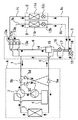
以下、この発明の実施の形態1を図にもとづいて説明する。図1は、実施の形態1による冷凍または空気調和装置の構成を示す冷媒回路図で、熱源機1台に対して複数台の室内機を接続する多室型ヒートポンプ空気調和装置の例を示しており、各室内機毎に冷暖房を選択的に行なうことができ、冷房を行なう室内機と、暖房を行なう室内機とを同時に運転することができる例を示している。なお、図1では熱源機1台に室内機2台、分流コントローラ1台を接続した場合について説明するが、3台以上の室内機、及び2台以上の分流コントローラを接続した場合でも同様に実施できることは云うまでもない。
【0011】
図1において、Aは熱源機、B、Cは後述するように互いに並列接続された室内機で、それぞれ同じ構成とされている。Dは熱源機Aと室内機B、Cとを接続する分流コントローラで、構成については後述する。
熱源機Aは以下に述べる各構成要素によって構成されている。即ち、圧縮機1と、この圧縮機1に接続され、冷媒の流通方向を切り換える四方切換弁2と、熱源側熱交換器3と、四方切換弁2及び圧縮機1の間に接続されたアキュムレータ4と、熱源側熱交換器3及び後述する第1の接続配管6の間に設けられ、熱源側熱交換器3から第1の接続配管6の方向へのみ冷媒流通を許容する第1の逆止弁5aと、四方切換弁2及び後述する第2の接続配管7の間に設けられ、第2の接続配管7から四方切換弁2の方向へのみ冷媒流通を許容する第2の逆止弁5bと、四方切換弁2及び第1の接続配管6の間に設けられ、四方切換弁2から第1の接続配管6の方向へのみ冷媒流通を許容する第3の逆止弁5cと、熱源側熱交換器3及び第2の接続配管7の間に設けられ、第2の接続配管7から熱源側熱交換器3の方向へのみ冷媒流通を許容する第4の逆止弁5dとから構成されている。
【0012】
また、室内機B、Cは、それぞれ負荷側熱交換器11b、11cと、各負荷側熱交換器11b、11cに直列接続された絞り装置等の流量制御装置12b、12cとで構成されている。なお、各流量制御装置12b、12cは、冷房時は負荷側熱交換器11b、11cの出口側の過熱度により、暖房時は同じく出口側の過冷却度により開閉状態が制御されるようにされている。更に、分流コントローラDは四方切換弁2と接続された太い第2の接続配管7及び熱源側熱交換器3と接続され、第2の接続配管7より細い第1の接続配管6によって熱源機Aと接続され、室内機B、Cの負荷側熱交換器11b、11cと接続された負荷側の第2の接続配管7b、7c及び室内機B、Cの流量制御装置12b、12cに接続された負荷側の第1の接続配管6b、6cによって各室内機B、Cと接続されると共に、以下に述べるような内部構成を有する。
【0013】
即ち、13は負荷側の第2の接続配管7b、7cを、第1の接続配管6または第2の接続配管7に切り換え可能に接続する弁装置で、一端が負荷側の第2の接続配管7b、7cにそれぞれ接続され、他端が一括接続されて第1の接続配管6に接続された2個の第1の弁装置13aと、一端が負荷側の第2の接続配管7b、7cにそれぞれ接続され、他端が一括接続されて第2の接続配管7に接続された2個の第2の弁装置13bとから構成され、第1の弁装置13aを開路、第2の弁装置13bを閉路することにより、負荷側の第2の接続配管7b、7cを第1の接続配管6に接続し、また、第1の弁装置13aを閉路、第2の弁装置13bを開路することにより、負荷側の第2の接続配管7b、7cを第2の接続配管7に接続するものである。
【0014】
また、第1の接続配管6の途中に気液分離器14が設けられ、その気相部が、第1の接続配管6の後半部を経て第1の弁装置13aに接続され、その液相部が第1の熱交換部15、開閉自在な第2の流量制御装置16及び第2の熱交換部17を介して負荷側の第1の接続配管6b、6cに接続されている。また、バイパス配管18に設けられた第3の流量制御装置19を経て気液分離器14からの液冷媒の一部が第2の熱交換部17及び第1の熱交換部15で熱交換し、気液分離器14からの液冷媒を過冷却して第2の接続配管7に戻るようにされている。
【0015】
このように構成された実施の形態1の冷凍または空気調和装置によって、上述したように大きく分けて3つの形態の運転が行なわれる。即ち、複数の室内機の総てで冷房運転を行なう場合と、複数の室内機の総てで暖房運転を行なう場合と、複数の室内機のうち一部は冷房運転を行ない、他の一部は暖房運転を行なう場合(冷暖房同時運転)とである。更に、冷暖房同時運転については、2つの形態の運転が行なわれる。即ち、複数の室内機のうち大部分の室内機が暖房運転を行なう場合(暖房主体運転)と、複数の室内機のうち大部分の室内機が冷房運転を行なう場合(冷房主体運転)とである。
【0016】
まず、図2を用いて総ての室内機を冷房運転する全冷房運転について説明する。即ち、図2に冷媒の流れを実線矢印で示すように、圧縮機1より吐出された高温高圧の冷媒ガスは四方切換弁2を通り、熱源側熱交換器3で熱交換して凝縮された後、第1の逆止弁5a、第1の接続配管6を通り、分流コントローラDへ流入する。分流コントローラDへ流入した冷媒は気液分離器14、第2の流量制御装置16の順に通り、負荷側の第1の接続配管6b、6cを通り、各室内機B、Cに流入し、各負荷側熱交換器11b、11cの出口の過熱度により制御される流量制御装置12b、12cにより低圧まで減圧されて負荷側熱交換器11b、11cで室内空気と熱交換して蒸発しガス化され室内を冷房する。
そして、ガス状態となった冷媒は、負荷側の第2の接続配管7b、7c、第2の弁装置13bを通り、第2の接続配管7、第2の逆止弁5b、四方切換弁2、アキュムレータ4を経て圧縮機1に吸入される循環サイクルを構成し、冷房運転を行なう。この時、第1の弁装置13aは閉路、第2の弁装置13bは開路されている。
【0017】
また、第2の接続配管7は低圧、第1の接続配管6は高圧のため必然的に第1の逆止弁5a、第2の逆止弁5bへ冷媒が流通する。
更に、このサイクルの時、第2の流量制御装置16を通過した冷媒の一部が第2の熱交換部17及び第3の流量制御装置19を経てバイパス配管18へ入り、第3の流量制御装置19で低圧まで減圧されて、第2の熱交換部17で負荷側の第1の接続配管6b、6cに流入する冷媒との間で熱交換を行ない、また、第1の熱交換部15で第2の流量制御装置16に流入する冷媒との間で熱交換を行ない蒸発した冷媒は、第2の接続配管7へ入り、第2の逆止弁5b、四方切換弁2、アキュムレータ4を経て圧縮機1に吸入される。一方、第1の熱交換部15で熱交換し、過冷却度が増大された冷媒は、負荷側の第1の接続配管6b、6cを経由して冷房しようとしている室内機B、Cへ流入する。
【0018】
次に、図3を用いて総ての室内機を暖房運転する全暖房運転について説明する。この場合は、四方切換弁2が切り換えられ、冷媒の流れが図3に実線矢印で示すようになる。即ち、圧縮機1より吐出された高温高圧の冷媒ガスは四方切換弁2を通り、第3の逆止弁5c、第1の接続配管6を通り、分流コントローラDへ流入する。分流コントローラDへ流入した冷媒は気液分離器14、第1の接続配管6の後半部を経て第1の弁装置13a、負荷側の第2の接続配管7b、7cを通り、各室内機B、Cに流入し、室内空気と熱交換して凝縮液化し、室内を暖房する。
【0019】
そして、液状態となった冷媒は、各負荷側熱交換器11b、11cの出口の過冷却度により制御される流量制御装置12b、12cを通り、負荷側の第1の接続配管6b、6cからバイパス配管18の第3の流量制御装置19に流入して低圧の気液二相状態まで減圧される。低圧まで減圧された冷媒は、第2の熱交換部17、第1の熱交換部15を経た後、第2の接続配管7を通り、第4の逆止弁5d、熱源側熱交換器3に流入し熱交換して蒸発しガス状態となった冷媒は、四方切換弁2、アキュムレータ4を経て圧縮機1に吸入される循環サイクルを構成し、暖房運転を行なう。この時、第1の弁装置13aは開路、第2の弁装置13bは閉路されている。また、第2の接続配管7は低圧、第1の接続配管6は高圧のため必然的に第3の逆止弁5c、第4の逆止弁5dへ冷媒が流通する。
【0020】
次に、冷暖房同時運転における暖房主体の場合について図4を用いて説明する。ここでは、室内機Bが暖房、室内機Dが冷房しようとしている場合について説明する。即ち、図4に冷媒の流れを実線矢印で示すように、圧縮機1より吐出された高温高圧の冷媒ガスは四方切換弁2、第3の逆止弁5c、第1の接続配管6を通り、分流コントローラDに流入する。分流コントローラDに流入した冷媒は気液分離器14、第1の接続配管6の後半部を経て第1の弁装置13a、負荷側の第2の接続配管7bの順に通り、暖房しようとしている室内機Bに流入し、負荷側熱交換器11bで室内空気と熱交換して凝縮液化し、室内を暖房する。
そして、液状態となった冷媒は、負荷側熱交換器11bの出口の過冷却度により制御され、ほぼ全開状態の流量制御装置12bを通り少し減圧されて高圧と低圧の中間の圧力(中間圧)になり、負荷側の第1の接続配管6bに流入した冷媒の一部が矢印Rのように第2の熱交換部17を経て冷房しようとしている室内機Cに接続された負荷側の第1の接続配管6cを通り、負荷側熱交換器11cの出口の過熱度により制御される流量制御装置12cにより減圧された後に室内機Cの負荷側熱交換器11cに入り熱交換して蒸発しガス状態となって室内を冷房し、室内機Cに接続された第2の弁装置13bを介して第2の接続配管7に流入する。
【0021】
一方、室内機Bから分流コントローラDの第2の熱交換部17に流入した室内機Bの暖房用の冷媒の他の一部は、バイパス配管18を経て第1の接続配管6の高圧と流量制御装置12bの出口の中間圧との差を一定にするように制御される開閉自在な第3の流量制御装置19を通って上述のように第2の接続配管7に至るため、ここで室内機Cを冷房した冷媒と合流して太い第2の接続配管7に流入し、第4の逆止弁5d、熱源側熱交換器3に流入し熱交換して蒸発しガス状態となった冷媒は、四方切換弁2、アキュムレータ4を経て圧縮機1に吸入される循環サイクルを構成し、暖房主体運転を行なう。
【0022】
この時、暖房しようとしている室内機Bに接続されている第1の弁装置13aは開路、第2の弁装置13bは閉路され、冷房しようとしている室内機Cに接続されている第1の弁装置13aは閉路、第2の弁装置13bは開路されている。
また、第2の接続配管7は低圧、第1の接続配管6は高圧のため必然的に第3の逆止弁5c、第4の逆止弁5dへ冷媒が流通する。
【0023】
また、このサイクルの時、バイパス配管18へ入った冷媒は、第3の流量制御装置19で低圧まで減圧されて、第2の熱交換部17で負荷側の第1の接続配管6cへ流入する冷媒との間で熱交換を行ない、更に第1の熱交換部15で第2の流量制御装置16へ流入する冷媒との間で熱交換を行ない蒸発した冷媒は、第2の接続配管7へ入り、第4の逆止弁5dを経て、熱源側熱交換器3に流入し熱交換して蒸発しガス状態となる。そして、この冷媒は四方切換弁2、アキュムレータ4を経て圧縮機1に吸入される。一方、第2の熱交換部17で熱交換し過冷却度が増大された冷媒は、上述のように、冷房しようとしている室内機Cへ流入する。
【0024】
次に、冷暖房同時運転における冷房主体の場合について図5を用いて説明する。ここでは、室内機Bが暖房、室内機Cが冷房しようとしている場合について説明する。即ち、図5に冷媒の流れを実線矢印で示すように、圧縮機1より吐出された高温高圧の冷媒ガスは四方切換弁2を通り、熱源側熱交換器3で任意量熱交換して気液2相の高温高圧冷媒となり、第1の逆止弁5a、第1の接続配管6を通り、分流コントローラDに流入する。分流コントローラDに流入した冷媒は気液分離器14へ送られ、ここで、ガス冷媒と液冷媒に分離される。分離されたガス冷媒は、第1の接続配管6の後半部を経て分流コントローラDの弁装置13の第1の弁装置13a、負荷側の第2の接続配管7bの順に通り、暖房しようとしている室内機Bに流入し、負荷側熱交換器11bで室内空気と熱交換して凝縮液化し、室内を暖房する。
【0025】
更に、負荷側熱交換器11bの出口の過冷却度により制御されほぼ全開状態の流量制御装置12bを通り少し減圧されて、高圧と低圧の中間の圧力(中間圧)となり、負荷側の第1の接続配管6bを経てバイパス配管18に流入し、第3の流量制御装置19で低圧まで減圧されて、第2の熱交換部17で負荷側の第1の接続配管6cに流入する冷媒との間で熱交換を行ない、また、第1の熱交換部15で第2の流量制御装置16へ流入する冷媒との間で熱交換を行ない蒸発した冷媒は、第2の接続配管7に至る。一方、分流コントローラDの気液分離器14で分離された残りの液冷媒は、第1の熱交換部15で熱交換して過冷却度が増大された後、高圧と中間圧の差を一定にするように制御される第2の流量制御装置16を通って矢印で示すように、負荷側の第1の接続配管6cを通り、室内機Cに流入する。そして、この冷媒は、室内機Cの負荷側熱交換器11cの出口の過熱度により制御される流量制御装置12cにより低圧まで減圧されて負荷側熱交換器11cで室内空気と熱交換して蒸発しガス化され室内を冷房する。
そして、ガス状態となった冷媒は、負荷側の第2の接続配管7c、第2の弁装置13bを経て第2の接続配管7へ流入し、バイパス配管18を経て第2の接続配管7に流入する上述の室内機Bの暖房用冷媒と合流した後、第2の逆止弁5b、四方切換弁2、アキュムレータ4を経て圧縮機1に吸入される循環サイクルを構成し、冷房主体運転を行なう。
【0026】
この時、冷房しようとしている室内機Cに接続されている第1の弁装置13aは閉路、第2の弁装置13bは開路され、暖房しようとしている室内機Bに接続されている第1の弁装置13aは開路、第2の弁装置13bは閉路されている。また、第2の接続配管7は低圧、第1の接続配管6は高圧のため必然的に第1の逆止弁5a、第2の逆止弁5bへ冷媒が流通する。
【0027】
この実施の形態による冷凍または空気調和装置は、以上のように構成されているため、液冷媒が流通する冷媒配管である第1の接続配管6は常に高圧で使用され、ガス冷媒が流通する冷媒配管である第2の接続配管7は常に低圧で使用される。従って、第1の接続配管6は高圧の設計圧力、第2の接続配管7は低圧の設計圧力で設計することができる。なお、一般にビル用マルチエアコンで使用されている冷媒としてR22があるが、この冷媒は高圧の設計圧力が約3MPa、低圧側で約1.6MPaであるため、冷媒にR22を使用する空気調和装置の既設配管として、市場で使用されている銅配管の許容圧力は表2に示されるようになっている。この空気調和装置の熱源機と室内機を例えばR410Aを冷媒に使用する空気調和装置に更新する場合には、高圧の設計圧力は表2に示すように、約4.2MPa、低圧の設計圧力は約2.2MPaである。
【0028】
このため、この発明における空気調和装置において、第1の接続配管6として径が15.88のものを、また、第2の接続配管7として径が28.6のものを使用すれば、両接続配管は、各々、設計圧力が配管の許容値以下となり、使用が可能である。従って、冷媒にR22を使用する冷凍または空気調和装置で使用していた既設配管がR410Aを使用する空気調和装置で流用可能となるので、空気調和装置の更新時に生じる既設の冷媒配管の廃材化や新規の冷媒配管を施工するための既設構造物の取り壊し等をなくすることができる他、工事期間も短縮することができる。
【0029】
また、一般に、動作圧力が高い冷媒では、配管を流れる冷媒の密度が大きくなり、同じ径の冷媒配管を使用しても、動作圧力が低い冷媒よりも動作圧力が高い冷媒の方が、圧力損失が小さくなる傾向がある。図6は、配管長に対する能力の低下比率を動作圧力の異なる冷媒に関して比較した図である。この図から、動作圧力が低い冷媒(R407C)よりも動作圧力が高い冷媒(R410A)の方が、能力が高くなることが分かる。従って、既設の冷媒配管を流用して動作圧力が高い冷媒を使用する冷凍または空気調和装置に更新することにより、冷凍または空気調和装置の効率を向上させることができる。
【0030】
更に、このような冷凍または空気調和装置を施工する場合の施工フローを図7に示す。手順は、まず、ステップS1で既設ユニット内の旧冷媒を回収する。
次に、ステップS2で既設の熱源機と室内機を撤去する。その後、ステップS3で既設の冷媒配管を洗浄する。次に、ステップS4で新規の熱源機と室内機を据え付ける。続いてステップS5で熱源機と室内機を既設もしくは新規の冷媒配管で接続する。次にステップS6で冷媒配管内を真空引きし、冷媒チャージを行なう。その後、ステップS7で試運転を実施し、更新工事を終了する。
これによって、既設配管内に残留するコンタミを除去した状態で既設配管を流用することができるので、冷凍または空気調和装置におけるコンタミ物質による装置の劣化や膨張弁の詰まりを防止し、機器の信頼性を高めることができる。
【0031】
また、冷媒としてR410Aを使用する場合には、冷凍または空気調和装置の運転を行なう時の動作圧力が高いため、上述のように、圧力損失が小さくなる。
この結果、熱源機と室内機とを接続する冷媒配管での圧力損失が小さくなることで、ロスが削減され、冷凍または空気調和装置の効率を向上させることができる。この効果は、更新前の冷凍または空気調和装置に使用される冷媒の動作圧力が更新後の装置に使用される冷媒の動作圧力よりも低いものであれば、R407C、R134a、R12、R13等、どのような冷媒を使用した場合にも期待することができる。また、R22は塩素を含む冷媒であるが、R410Aに置き換えることでオゾン破壊係数が0の冷媒となるので、地球環境保護にも役立つものである。
【0032】
更に、更新後の冷媒をR32とすることによって、地球温暖化係数を小さくすることができるので、この場合にも地球環境保護に役立つものである。
また、流用する既設冷媒配管を装置の更新時に洗浄することにより、既設システムで発生し既設冷媒配管中に残留していた冷凍機油の劣化物等のコンタミを除去した状態で、新しいシステムを構成することができるので、冷凍または空気調和装置の信頼性を高めることができる。
【0033】
【発明の効果】
この発明に係る冷凍または空気調和装置によれば、既設の冷媒配管を用いて更新前の冷凍または空気調和装置の設計圧力よりも高い設計圧力を持つ冷凍または空気調和装置に更新するようにしているため、熱源機及び室内機の少なくとも一方を更新する場合における更新工事の工期を短縮し、更新コストを低減することができる。また、冷媒配管での圧力損失を低減することで冷凍または空気調和装置の効率を改善することができる。更に、R22のように塩素を含む冷媒をR410Aのようにオゾン破壊係数が0の冷媒と置き換えれば地球環境保護にも役立つことができ、さらに、更新後の冷媒をR32とすれば、地球温暖化係数を小さくすることができ、地球環境保護に役立つものである。
また、流用する既設冷媒配管を洗浄することにより、既設システムで発生し既設冷媒配管中に残留していた冷凍機油の劣化物等のコンタミを除去した状態で新しいシステムを構成することができるので、冷凍または空気調和装置の信頼性を高めることができる。
【図面の簡単な説明】
【図1】この発明の実施の形態1による冷凍または空気調和装置の構成を示す冷媒回路図である。
【図2】実施の形態1における全冷房運転時の冷媒の流れを示す説明図である。
【図3】実施の形態1における全暖房運転時の冷媒の流れを示す説明図である。
【図4】実施の形態1における暖房主体運転時の冷媒の流れを示す説明図である。
【図5】実施の形態1における冷房主体運転時の冷媒の流れを示す説明図である。
【図6】配管長に対する冷媒の性能比率を示す説明図である。
【図7】この発明における装置更新時の手順を示すフロー図である。
【符号の説明】
1 圧縮機、 2 四方切換弁、 3 熱源側熱交換器、4 アキュムレータ、 5a 第1の逆止弁、 5b 第2の逆止弁、5c 第3の逆止弁、 5d 第4の逆止弁、 6 第1の接続配管、6b、6c 負荷側の第1の接続配管、 7 第2の接続配管、7b、7c 負荷側の第2の接続配管、11b、11c 負荷側熱交換器、 12b、12c 流量制御装置、13 弁装置、 13a 第1の弁装置、 13b 第2の弁装置、14 気液分離器、 15 第1の熱交換部、16 第2の流量制御装置、 17 第2の熱交換部、18 バイパス配管、 19 第3の流量制御装置、 A 熱源機、B、C 室内機、 D 分流コントローラ。[0001]
TECHNICAL FIELD OF THE INVENTION
The present invention diverts an existing refrigerant pipe for an old refrigerant to a refrigerant pipe connecting a refrigeration or air conditioning apparatus, particularly, a heat source unit and an indoor unit, and updates the heat source unit and the indoor unit to equipment for a new refrigerant. It relates to a refrigeration or air conditioner.
[0002]
[Prior art]
This type of conventional refrigeration or air conditioner generally includes a refrigerant circuit having the following devices and functions. That is, a compressor, a four-way switching valve that switches the direction in which the high-temperature and high-pressure gas refrigerant discharged from the compressor flows between a cooling operation and a heating operation, and acts as a condenser during cooling, and as an evaporator during heating. A heat source side heat exchanger that acts, and a heat source unit composed of an accumulator that separates the gas refrigerant returned from the evaporator into gas-liquid and returns it to the compressor, and acts as an evaporator during cooling and as a condenser during heating An indoor unit including a load-side heat exchanger that operates and a flow control device such as a throttle device connected to the load-side heat exchanger, and first and second connection pipes that connect the heat source unit and the indoor unit. Constitute a refrigerant circuit.
[0003]
In the refrigeration or air-conditioning apparatus having such a refrigerant circuit, the flow of the refrigerant when performing the cooling operation will be described. The high-temperature, high-pressure gas refrigerant discharged from the compressor flows into the heat source side heat exchanger via the four-way switching valve, where it is condensed and liquefied.
The liquefied refrigerant flows through the first connection pipe, which is a liquid pipe, into the expansion device of the indoor unit, where it is throttled to a low pressure, flows into the load side heat exchanger, and evaporates and evaporates.
The low-pressure gas refrigerant that has exited the load-side heat exchanger reaches the four-way switching valve of the heat source unit via the second connection pipe, which is a gas pipe, and then returns to the compressor via the accumulator.
[0004]
Next, the flow of the refrigerant when performing the heating operation will be described. The flow path of the high-temperature, high-pressure gas refrigerant discharged from the compressor is switched by a four-way switching valve, flows into the load-side heat exchanger of the indoor unit via the second connection pipe that is a gas pipe, and condenses there. Liquefy. The liquefied refrigerant is throttled to a low pressure by the expansion device to become a low-pressure two-phase refrigerant, and flows into the heat source side heat exchanger of the heat source device via the first connection pipe which is a liquid pipe. Here, after the two-phase refrigerant evaporates and evaporates, the low-pressure gas refrigerant returns to the compressor via the four-way switching valve and the accumulator. (See, for example, Patent Document 1).
[0005]
[Patent Document 1]
Japanese Patent No. 3361765 (paragraphs 0063-0073, FIG. 1)
[0006]
[Problems to be solved by the invention]
Since the conventional refrigeration or air-conditioning apparatus is configured as described above, the four-way switching valve switches between the cooling operation and the heating operation, and the flow of the refrigerant flowing to the indoor unit is reversed. As a result, in the first and second connection pipes connecting the heat source unit and the indoor unit, the first connection pipe, which is a liquid pipe, has a high pressure and the second connection pipe, which is a gas pipe, has a low pressure during cooling. On the other hand, during heating, the first connection pipe, which is a liquid pipe, has a low pressure, and the second connection pipe, which is a gas pipe, has a high pressure. Here, the allowable pressure of a refrigerant pipe for an air conditioner generally used in the market differs depending on the pipe diameter, and as shown in Table 1, as the pipe diameter increases, the allowable pressure decreases.
[Table 1]
On the other hand, in a multi-air conditioner for buildings using R22 or R407C as a refrigerant, as shown in Table 2, the design pressure of the high pressure is close to the allowable pressure of the gas pipes. Of the heat source units and the indoor units are limited to those using a refrigerant close to the operating pressure of the heat source unit and the indoor units before the update.
[Table 2]
Furthermore, as the demand for energy savings has been increasing year by year, it has not been possible to satisfy these demands simply by improving the performance of the elements used in the equipment, and the cost tolerance of the equipment has been reduced. there were.
[0008]
The present invention has been made to solve the above-described problems, and the existing refrigerant piping is diverted to shorten the period of renewal work, reduce renewal costs, and reduce pressure loss in the refrigerant piping. Accordingly, it is an object of the present invention to provide a refrigeration or air-conditioning apparatus that improves the efficiency of the apparatus and also contributes to protection of the global environment, and a method of updating the same.
[0009]
[Means for Solving the Problems]
A refrigeration or air-conditioning apparatus according to the present invention is a heat source having a compressor, a four-way switching valve for switching a flow path of a refrigerant discharged from the compressor, and a heat source side heat exchanger connected to the four-way switching valve. Unit, an indoor unit having a load-side heat exchanger and a flow control device connected thereto, and connecting the heat source unit and the indoor unit via first and second connection pipes, In a refrigeration or air conditioner equipped with a flow dividing controller having a valve device for switchably connecting one end of a heat exchanger to the first and second connection pipes, the first and second connection pipes are connected to each other. An existing connection pipe for the old refrigerant is provided, and at least one of the heat source unit and the indoor unit is an updater for a new refrigerant having a higher operating pressure than the old refrigerant.
[0010]
BEST MODE FOR CARRYING OUT THE INVENTION
Hereinafter, a first embodiment of the present invention will be described with reference to the drawings. FIG. 1 is a refrigerant circuit diagram illustrating a configuration of a refrigeration or air-conditioning apparatus according to
[0011]
In FIG. 1, A is a heat source unit, and B and C are indoor units connected in parallel to each other as described later, and have the same configuration. D is a shunt controller that connects the heat source unit A and the indoor units B and C, and the configuration will be described later.
The heat source device A is constituted by the components described below. That is, a
[0012]
Further, the indoor units B and C are respectively constituted by load-
[0013]
That is,
[0014]
Further, a gas-
[0015]
With the refrigeration or air-conditioning apparatus of the first embodiment configured as described above, the three types of operation are roughly divided as described above. That is, when the cooling operation is performed by all of the plurality of indoor units, when the heating operation is performed by all of the plurality of indoor units, a part of the plurality of indoor units performs the cooling operation, and the other Is the case where the heating operation is performed (simultaneous cooling and heating operation). Further, for simultaneous cooling and heating operation, two modes of operation are performed. That is, a case where most of the indoor units among the plurality of indoor units perform the heating operation (heating-main operation), and a case where most of the indoor units among the plurality of indoor units perform the cooling operation (cooling-main operation). is there.
[0016]
First, a cooling only operation for cooling all the indoor units will be described with reference to FIG. That is, as shown by a solid line arrow in FIG. 2, the high-temperature and high-pressure refrigerant gas discharged from the
The gaseous refrigerant passes through the
[0017]
Further, since the
Further, during this cycle, a part of the refrigerant that has passed through the second
[0018]
Next, a heating only operation for heating all the indoor units will be described with reference to FIG. In this case, the four-
[0019]
Then, the refrigerant in the liquid state passes through the
[0020]
Next, the case of mainly heating in the simultaneous cooling and heating operation will be described with reference to FIG. Here, a case where the indoor unit B is about to heat and the indoor unit D is about to cool will be described. That is, as shown by the solid arrows in FIG. 4, the high-temperature and high-pressure refrigerant gas discharged from the
The refrigerant in the liquid state is controlled by the degree of supercooling at the outlet of the load side heat exchanger 11b, and is slightly reduced in pressure through the
[0021]
On the other hand, another part of the refrigerant for heating the indoor unit B flowing from the indoor unit B to the second
[0022]
At this time, the
In addition, since the
[0023]
In this cycle, the refrigerant that has entered the
[0024]
Next, a case where cooling is mainly performed in simultaneous cooling and heating operation will be described with reference to FIG. Here, a case where the indoor unit B is about to heat and the indoor unit C is about to cool will be described. That is, as shown by the solid line arrows in FIG. 5, the high-temperature and high-pressure refrigerant gas discharged from the
[0025]
Further, the pressure is controlled by the degree of supercooling at the outlet of the load-side heat exchanger 11b, and is slightly reduced through the
Then, the gaseous refrigerant flows into the
[0026]
At this time, the
[0027]
Since the refrigeration or air-conditioning apparatus according to this embodiment is configured as described above, the
[0028]
For this reason, in the air conditioner of the present invention, if the
[0029]
Also, in general, in a refrigerant having a high operating pressure, the density of the refrigerant flowing through the pipe increases, and even when a refrigerant pipe having the same diameter is used, a refrigerant having a high operating pressure has a higher pressure loss than a refrigerant having a low operating pressure. Tend to be smaller. FIG. 6 is a diagram comparing the rate of decrease in capacity with respect to pipe length for refrigerants having different operating pressures. From this figure, it can be seen that the capacity of the refrigerant (R410A) having a higher operating pressure is higher than that of the refrigerant (R407C) having a lower operating pressure. Therefore, the efficiency of the refrigeration or air-conditioning apparatus can be improved by diverting the existing refrigerant pipe to a refrigeration or air-conditioning apparatus using a refrigerant having a high operating pressure.
[0030]
FIG. 7 shows a construction flow when such a refrigeration or air-conditioning apparatus is constructed. The procedure first recovers the old refrigerant in the existing unit in step S1.
Next, in step S2, the existing heat source unit and indoor unit are removed. Then, the existing refrigerant pipe is washed in step S3. Next, in step S4, a new heat source unit and an indoor unit are installed. Subsequently, in step S5, the heat source unit and the indoor unit are connected by an existing or new refrigerant pipe. Next, in step S6, the inside of the refrigerant pipe is evacuated to charge the refrigerant. Thereafter, a trial operation is performed in step S7, and the renewal work ends.
As a result, the existing pipes can be reused in a state where the contaminants remaining in the existing pipes are removed, thereby preventing equipment deterioration and clogging of expansion valves due to contaminants in the refrigeration or air-conditioning apparatus, and reliability of the equipment. Can be increased.
[0031]
Further, when R410A is used as the refrigerant, the operating pressure during operation of the refrigeration or air conditioner is high, so that the pressure loss is reduced as described above.
As a result, the pressure loss in the refrigerant pipe connecting the heat source unit and the indoor unit is reduced, so that the loss is reduced and the efficiency of the refrigeration or air conditioner can be improved. This effect can be obtained if the operating pressure of the refrigerant used in the refrigeration or air-conditioning apparatus before the update is lower than the operating pressure of the refrigerant used in the apparatus after the update, such as R407C, R134a, R12, R13, and the like. This can be expected when any refrigerant is used. Further, R22 is a refrigerant containing chlorine, but since it becomes a refrigerant having an ozone depletion coefficient of 0 by replacing it with R410A, it is also useful for protecting the global environment.
[0032]
Furthermore, by setting the refrigerant after the update to R32, the global warming potential can be reduced, which is also useful for protecting the global environment.
In addition, a new system is configured by cleaning existing refrigerant pipes to be diverted at the time of updating the apparatus, thereby removing contaminants such as deterioration of refrigerating machine oil generated in the existing system and remaining in the existing refrigerant pipes. Therefore, the reliability of the refrigeration or air conditioner can be improved.
[0033]
【The invention's effect】
According to the refrigeration or air-conditioning apparatus according to the present invention, the refrigeration or air-conditioning apparatus having a design pressure higher than the design pressure of the refrigeration or air-conditioning apparatus before the update is updated using the existing refrigerant pipe. Therefore, it is possible to shorten the period of the renewal work when renewing at least one of the heat source unit and the indoor unit, and to reduce the renewal cost. Further, the efficiency of the refrigeration or air conditioner can be improved by reducing the pressure loss in the refrigerant pipe. Further, replacing a refrigerant containing chlorine such as R22 with a refrigerant having an ozone depletion potential of 0, such as R410A, can also help protect the global environment. Further, if the updated refrigerant is R32, global warming can be achieved. The coefficient can be reduced, which is useful for protecting the global environment.
In addition, by cleaning the existing refrigerant pipe to be diverted, a new system can be configured in a state in which contamination such as deterioration of refrigerating machine oil generated in the existing system and remaining in the existing refrigerant pipe has been removed, The reliability of the refrigeration or air conditioner can be improved.
[Brief description of the drawings]
FIG. 1 is a refrigerant circuit diagram showing a configuration of a refrigeration or air-conditioning apparatus according to
FIG. 2 is an explanatory diagram showing a flow of a refrigerant during a cooling only operation in the first embodiment.
FIG. 3 is an explanatory diagram illustrating a flow of a refrigerant during a heating only operation in the first embodiment.
FIG. 4 is an explanatory diagram illustrating a flow of a refrigerant during a heating-main operation according to the first embodiment.
FIG. 5 is an explanatory diagram showing a flow of a refrigerant during a cooling main operation in the first embodiment.
FIG. 6 is an explanatory diagram showing a performance ratio of a refrigerant to a pipe length.
FIG. 7 is a flowchart showing a procedure at the time of updating a device according to the present invention.
[Explanation of symbols]
Claims (4)
Priority Applications (1)
| Application Number | Priority Date | Filing Date | Title |
|---|---|---|---|
| JP2003106523A JP4393786B2 (en) | 2003-04-10 | 2003-04-10 | Refrigeration or air conditioner and method for updating the same |
Applications Claiming Priority (1)
| Application Number | Priority Date | Filing Date | Title |
|---|---|---|---|
| JP2003106523A JP4393786B2 (en) | 2003-04-10 | 2003-04-10 | Refrigeration or air conditioner and method for updating the same |
Publications (2)
| Publication Number | Publication Date |
|---|---|
| JP2004309088A true JP2004309088A (en) | 2004-11-04 |
| JP4393786B2 JP4393786B2 (en) | 2010-01-06 |
Family
ID=33468689
Family Applications (1)
| Application Number | Title | Priority Date | Filing Date |
|---|---|---|---|
| JP2003106523A Expired - Lifetime JP4393786B2 (en) | 2003-04-10 | 2003-04-10 | Refrigeration or air conditioner and method for updating the same |
Country Status (1)
| Country | Link |
|---|---|
| JP (1) | JP4393786B2 (en) |
Cited By (5)
| Publication number | Priority date | Publication date | Assignee | Title |
|---|---|---|---|---|
| JP2008298335A (en) * | 2007-05-30 | 2008-12-11 | Fujitsu General Ltd | Refrigerating device, additional refrigerant filling kit used in the same, and additional refrigerant filling method of refrigerating device |
| JP2009299910A (en) * | 2008-06-10 | 2009-12-24 | Hitachi Appliances Inc | Air conditioner |
| WO2013145013A1 (en) * | 2012-03-29 | 2013-10-03 | 三菱電機株式会社 | Branch controller and air-conditioning device provided therewith |
| WO2014103173A1 (en) | 2012-12-28 | 2014-07-03 | ダイキン工業株式会社 | Air conditioner and air conditioner construction method |
| US9506674B2 (en) | 2009-01-15 | 2016-11-29 | Mitsubishi Electric Corporation | Air conditioner including a bypass pipeline for a defrosting operation |
-
2003
- 2003-04-10 JP JP2003106523A patent/JP4393786B2/en not_active Expired - Lifetime
Cited By (10)
| Publication number | Priority date | Publication date | Assignee | Title |
|---|---|---|---|---|
| JP2008298335A (en) * | 2007-05-30 | 2008-12-11 | Fujitsu General Ltd | Refrigerating device, additional refrigerant filling kit used in the same, and additional refrigerant filling method of refrigerating device |
| JP2009299910A (en) * | 2008-06-10 | 2009-12-24 | Hitachi Appliances Inc | Air conditioner |
| US9506674B2 (en) | 2009-01-15 | 2016-11-29 | Mitsubishi Electric Corporation | Air conditioner including a bypass pipeline for a defrosting operation |
| WO2013145013A1 (en) * | 2012-03-29 | 2013-10-03 | 三菱電機株式会社 | Branch controller and air-conditioning device provided therewith |
| WO2014103173A1 (en) | 2012-12-28 | 2014-07-03 | ダイキン工業株式会社 | Air conditioner and air conditioner construction method |
| JP2014129948A (en) * | 2012-12-28 | 2014-07-10 | Daikin Ind Ltd | Air conditioner and air conditioner construction method |
| CN104870906A (en) * | 2012-12-28 | 2015-08-26 | 大金工业株式会社 | Air conditioner and air conditioner construction method |
| AU2013368096B2 (en) * | 2012-12-28 | 2016-05-05 | Daikin Industries, Ltd. | Air conditioner and air conditioner construction method |
| US10184676B2 (en) | 2012-12-28 | 2019-01-22 | Daikin Industries, Ltd. | Air conditioner having simultaneous heating and cooling |
| US10443869B2 (en) | 2012-12-28 | 2019-10-15 | Daikin Industries, Ltd. | Air conditioner construction method |
Also Published As
| Publication number | Publication date |
|---|---|
| JP4393786B2 (en) | 2010-01-06 |
Similar Documents
| Publication | Publication Date | Title |
|---|---|---|
| JP5239824B2 (en) | Refrigeration equipment | |
| US9791193B2 (en) | Air conditioner and method of controlling the same | |
| JP4888500B2 (en) | Refrigeration equipment | |
| KR100688171B1 (en) | Multiple air conditioner and refrigerant withdrawing method | |
| JP6003635B2 (en) | AIR CONDITIONER AND AIR CONDITIONER CONSTRUCTION METHOD | |
| US9677790B2 (en) | Multi-room air-conditioning apparatus | |
| JP2007240025A (en) | Refrigerating device | |
| JP5125611B2 (en) | Refrigeration equipment | |
| JP2014129947A (en) | Air conditioner | |
| WO2017010007A1 (en) | Air conditioner | |
| KR20100032200A (en) | Air conditioner | |
| WO2004013550A1 (en) | Refrigeration equipment | |
| JP6539560B2 (en) | Air conditioner | |
| JP4393786B2 (en) | Refrigeration or air conditioner and method for updating the same | |
| JP2010169309A (en) | Air conditioner | |
| JPH10160299A (en) | Freezer | |
| KR100526204B1 (en) | A refrigerator | |
| CN114450528B (en) | Air conditioner | |
| JP2010014343A (en) | Refrigerating device | |
| JP4063229B2 (en) | Piping cleaning method and piping cleaning device | |
| JP2006125762A (en) | Indoor unit, air conditioning device comprising the same, and its operating method | |
| KR100702040B1 (en) | Multiple air conditioner | |
| JP4279080B2 (en) | Refrigeration air conditioner and update method thereof | |
| JP2006125761A (en) | Indoor machine and air conditioner comprising the same | |
| KR100463549B1 (en) | Multi-type air conditioner for cooling/heating the same time |
Legal Events
| Date | Code | Title | Description |
|---|---|---|---|
| A621 | Written request for application examination |
Free format text: JAPANESE INTERMEDIATE CODE: A621 Effective date: 20060203 |
|
| A977 | Report on retrieval |
Free format text: JAPANESE INTERMEDIATE CODE: A971007 Effective date: 20080428 |
|
| A131 | Notification of reasons for refusal |
Free format text: JAPANESE INTERMEDIATE CODE: A131 Effective date: 20090203 |
|
| A521 | Request for written amendment filed |
Free format text: JAPANESE INTERMEDIATE CODE: A523 Effective date: 20090331 |
|
| RD02 | Notification of acceptance of power of attorney |
Free format text: JAPANESE INTERMEDIATE CODE: A7422 Effective date: 20090331 |
|
| A02 | Decision of refusal |
Free format text: JAPANESE INTERMEDIATE CODE: A02 Effective date: 20090602 |
|
| A521 | Request for written amendment filed |
Free format text: JAPANESE INTERMEDIATE CODE: A523 Effective date: 20090821 |
|
| A911 | Transfer to examiner for re-examination before appeal (zenchi) |
Free format text: JAPANESE INTERMEDIATE CODE: A911 Effective date: 20090909 |
|
| TRDD | Decision of grant or rejection written | ||
| A01 | Written decision to grant a patent or to grant a registration (utility model) |
Free format text: JAPANESE INTERMEDIATE CODE: A01 Effective date: 20091013 |
|
| A01 | Written decision to grant a patent or to grant a registration (utility model) |
Free format text: JAPANESE INTERMEDIATE CODE: A01 |
|
| A61 | First payment of annual fees (during grant procedure) |
Free format text: JAPANESE INTERMEDIATE CODE: A61 Effective date: 20091014 |
|
| R150 | Certificate of patent or registration of utility model |
Ref document number: 4393786 Country of ref document: JP Free format text: JAPANESE INTERMEDIATE CODE: R150 Free format text: JAPANESE INTERMEDIATE CODE: R150 |
|
| FPAY | Renewal fee payment (event date is renewal date of database) |
Free format text: PAYMENT UNTIL: 20121023 Year of fee payment: 3 |
|
| FPAY | Renewal fee payment (event date is renewal date of database) |
Free format text: PAYMENT UNTIL: 20131023 Year of fee payment: 4 |
|
| R250 | Receipt of annual fees |
Free format text: JAPANESE INTERMEDIATE CODE: R250 |
|
| R250 | Receipt of annual fees |
Free format text: JAPANESE INTERMEDIATE CODE: R250 |
|
| R250 | Receipt of annual fees |
Free format text: JAPANESE INTERMEDIATE CODE: R250 |
|
| R250 | Receipt of annual fees |
Free format text: JAPANESE INTERMEDIATE CODE: R250 |
|
| R250 | Receipt of annual fees |
Free format text: JAPANESE INTERMEDIATE CODE: R250 |
|
| R250 | Receipt of annual fees |
Free format text: JAPANESE INTERMEDIATE CODE: R250 |
|
| R250 | Receipt of annual fees |
Free format text: JAPANESE INTERMEDIATE CODE: R250 |
|
| R250 | Receipt of annual fees |
Free format text: JAPANESE INTERMEDIATE CODE: R250 |
|
| EXPY | Cancellation because of completion of term |