JP2004305440A - Game system and game machine - Google Patents
Game system and game machine Download PDFInfo
- Publication number
- JP2004305440A JP2004305440A JP2003103483A JP2003103483A JP2004305440A JP 2004305440 A JP2004305440 A JP 2004305440A JP 2003103483 A JP2003103483 A JP 2003103483A JP 2003103483 A JP2003103483 A JP 2003103483A JP 2004305440 A JP2004305440 A JP 2004305440A
- Authority
- JP
- Japan
- Prior art keywords
- game
- gaming machine
- cpu
- display
- signal
- Prior art date
- Legal status (The legal status is an assumption and is not a legal conclusion. Google has not performed a legal analysis and makes no representation as to the accuracy of the status listed.)
- Pending
Links
Images


Classifications
-
- G—PHYSICS
- G07—CHECKING-DEVICES
- G07F—COIN-FREED OR LIKE APPARATUS
- G07F17/00—Coin-freed apparatus for hiring articles; Coin-freed facilities or services
- G07F17/32—Coin-freed apparatus for hiring articles; Coin-freed facilities or services for games, toys, sports, or amusements
Landscapes
- Physics & Mathematics (AREA)
- General Physics & Mathematics (AREA)
- Slot Machines And Peripheral Devices (AREA)
- Display Devices Of Pinball Game Machines (AREA)
- Pinball Game Machines (AREA)
Abstract
Description
【0001】
【発明の属する技術分野】
本発明は、遊技システム及び遊技機に関する。
【0002】
【従来の技術】
遊技場では、スロットマシンを始めとする様々な遊技機が設置され、また、ポーカゲーム、ルーレット、キノなどの所謂テーブルゲームが行われている。このため、例えばスロットマシンの遊技のみを連続して行うことに遊技者が単調さを感じ、他の遊技を行いたいと感じる場合があり得る。
【0003】
しかし、スロットマシンを離れて、遊技内容の異なる、他の場所に設置された遊技に参加することに煩わしさがあり、遊技者に同じスロットマシンで遊技を継続させることが難しかった。
【0004】
そこで、この問題を解決するため、スロットマシンの可変表示部の他に、第二の遊技のために別の表示部を設け、可変表示部での停止図柄に数字を対応させてビンゴゲームを行う遊技機が提案されている(例えば特許文献1参照)。
【0005】
【特許文献1】
特開平11−253610号公報
【0006】
【発明が解決しようとする課題】
しかしながら、このような遊技では、遊技者の遊技内容の異なる他の遊技を行いたいという意思を満足させることができず、結果として、第二の遊技に対しても退屈感を抱かせてしまうおそれがある。
【0007】
一例として、遊技者に対し、遊技内容の異なる、他の場所に設置された遊技、すなわち競馬ゲーム、ルーレット、キノなど、複数の遊技者により参加可能な遊技に参加したいとさせる場合がある。しかし、これらの遊技がスロットマシンとは異なる場所で行われていると、遊技者が遊技機を移動する煩わしさがある。また、競馬ゲーム、ルーレット、キノなどの遊技には参加可能人数に限りがあるため、スロットマシンの遊技者がスロットを中断して、競馬ゲーム、ルーレット、キノなどの遊技に参加しようとしても遊技に参加できない場合があり、気軽に遊技内容の異なる遊技に参加することはできない。
【0008】
本発明は、上記の如き問題に鑑みてなされたものであり、スロットマシンなどの第一の遊技を行っている遊技者が、遊技機を移動することなく、遊技内容の異なる第二の遊技に参加可能とならしめる遊技システム及び遊技機を提供するものである。
【0009】
【課題を解決するための手段】
以上のような目的を達成するために、本発明の遊技システム及び遊技機において、第一の遊技機は、第一の遊技を表示する可変表示部とは別の第二の表示部を設け、第二の遊技機と通信可能な状態に接続され前記第二の遊技機で制御される第二の遊技に関する情報を送受信し、遊技者に対し前記第二の遊技に関する情報に基づき前記第二の表示部において第二の遊技を行い得る機能を有することを特徴とする。
【0010】
より具体的には、本発明では、以下のようなものを提供する。
【0011】
(1) 遊技者により操作可能な操作部を有して第一の遊技を提供する第一の遊技機と、当該第一の遊技とは異なり、複数の遊技者により参加可能な第二の遊技を提供する第二の遊技機と、が通信可能な状態に接続された遊技システムであって、前記第二の遊技機は、前記第二の遊技を制御するプログラムを格納するプログラム格納手段と、前記プログラムを実行するプログラム実行手段と、前記第二の遊技に関する画像データを記憶する画像データ記憶手段と、前記第二の遊技に関する画像データを前記第一の遊技機に対して送信する画像データ送信手段と、を含む第二の遊技制御手段を備え、前記第一の遊技機は、第一の遊技を制御する第一の遊技制御手段と、前記第一の遊技に必要な複数の図柄を可変表示する第一の表示手段と、前記第二の遊技機から送信された前記第二の遊技に関する画像データを受信する画像データ受信手段と、前記第二の遊技に関する画像データに基づく画像を表示する第二の表示手段と、前記第二の遊技の遊技制御手段を操作する遊技操作手段と、を備えたことを特徴とする遊技システム。
【0012】
(2) 遊技者により操作可能な操作部を有して第一の遊技を提供する第一の遊技機であって、前記第一の遊技とは異なり、複数の遊技者により参加可能な第二の遊技を提供する第二の遊技機と通信可能な状態に接続され、第一の遊技を制御する第一の遊技制御手段と、前記第一の遊技に必要な複数の図柄を可変表示する第一の表示手段と、前記第二の遊技機から送信された前記第二の遊技に関する画像データを受信する画像データ受信手段と、前記第二の遊技に関する画像データに基づく画像を表示する第二の表示手段と、前記第二の遊技の遊技内容を操作するための遊技操作手段と、を備えたことを特徴とする遊技機。
【0013】
(1)及び(2)の発明によれば、第一の遊技機は「第一の遊技に必要な複数の図柄を可変表示する第一の表示手段と、前記第二の遊技機から送信された前記第二の遊技に関する画像データを受信する画像データ受信手段と、前記第二の遊技に関する画像データに基づく画像を表示する第二の表示手段と」を備えるため、第一の遊技を行う遊技者に対し、その第一の遊技に単調さを感じさせた場合において、第二の遊技を行うべく他の遊技機に移動することを試みることがあり、このとき他の遊技機に移動する煩わしさがあると、第二の遊技を行う意思が減殺される可能性があるが、他の場所に設置された遊技機に移動することなく第一の遊技を行っていた遊技機において第二の遊技へ参加可能とさせることにより、遊技者の第二の遊技への参加が促進され、遊技者による遊技の選択性を向上させることになり、遊技場全体の稼働効率を高めることができる。
【0014】
また、より多くの遊技者に対し、第二の遊技への参加の機会を提供することができる。
【0015】
更に、「前記第二の遊技の内容を操作するための遊技操作手段」を備えたため、第一の遊技機において第二の遊技機により制御される遊技の操作が可能となり、遊技者に対し、第二の遊技機から離れた場所で第二の遊技の内容を操作可能とさせることができる。
【0016】
また、第二の遊技機は「前記第二の遊技を制御するプログラムを格納するプログラム格納手段と、前記プログラムを実行するプログラム実行手段と、前記第二の遊技に関する画像データを記憶する画像データ記憶手段と、前記第二の遊技に関する画像データを前記第一の遊技機に対して送信する画像データ送信手段と」を備えたため、第一の遊技機において第二の遊技の制御を行う必要がなく、簡便な制御構造を以って第一の遊技機において第二の遊技が実行可能となる。
【0017】
例えば、競馬ゲーム、ルーレット、キノなどの複数の遊技者により参加可能な遊技の場合、これらの遊技機がスロットマシンとは異なる場所に配置されていると、スロットマシンの遊技者が遊技を中断して競馬ゲーム、ルーレット、キノなどの遊技に参加したいときに遊技機を移動しなければならない煩わしさがある。また、競馬ゲーム、ルーレット、キノなどの遊技への参加可能人数には限りがあるため、スロットマシンの遊技者がスロットを中断して、競馬ゲーム、ルーレット、キノなどの遊技に参加しようとしても、遊技に参加できない場合がある。しかし、本発明を利用することにより、遊技機を移動しなければならない煩わしさから解放され、気軽に複数の遊技者により参加可能な遊技に参加が可能となり、スロットマシンの遊技者が、遊技を中断してその他の遊技に参加したいときに、遊技機を移動することなく、その他の遊技に参加可能となる。そのため、競馬ゲーム、ルーレット、キノなどの複数の遊技者により参加可能な遊技への参加を促進することになり、遊技者によりスロット、または競馬ゲーム、ルーレット、キノなどの複数の遊技者により参加可能な遊技のいずれかが選択されて遊技を行う選択性が向上するので、遊技場全体の稼働効率を高めることができる。
【0018】
【発明の実施の形態】
以下に、本発明に好適な3つの実施形態について図面に基づいて説明する。
【0019】
以下の実施形態では、遊技価値を表す媒体として「コイン」を用いて説明するが、例えば「通貨」、「トークン」、「磁気カードまたはICチップに記憶された遊技価値情報」、「遊技球」、「メダル」、その他「コイン」に代わる遊技価値を持ち得る、いずれの媒体を用いてもよい。
【0020】
[第一の実施形態]
第一の実施形態では、本発明の第一の遊技を「スロット」とし、第二の遊技を「競馬ゲーム」とした場合を示す。
【0021】
[遊技機のネットワーク構成]
図1に示す遊技システムS1は、ネットワークNと、複数の遊技機100と、遊技機200と、から構成される。
【0022】
本実施形態におけるネットワークNは、本遊技システムS1の所定のプロトコルに基づく専用回線で構成されたネットワークである。
【0023】
なお、ネットワークNは特定のプロトコル及び専用回線によるものに限定されるものではなく、TCP/IPまたはUDP/IPプロトコル及び公衆回線網で構成されるインターネットで構成されてもよい。
【0024】
本実施形態における遊技機100及び遊技機200は、各遊技場に設置され、遊技者により遊技の操作が行なわれるものである。遊技機100は一般的なスロットマシンであり、遊技機200は、複数人数が参加可能の一般的な競馬ゲームである。それらの構成要素及び機能については後述する。
【0025】
[遊技機100の概観]
本実施形態の遊技機100の概観を図2に示す。
【0026】
遊技機100の全体を形成している筐体199の正面には、略垂直に形成された縦長矩形の3つの表示窓198(198L、198C、198R)が設けられている。これらの表示窓198(198L,198C,198R)には、5本の入賞ライン、即ち、水平に3本(中央L1、上下L2、L3)、及び斜めに2本(斜め右下がりL4、斜め右上がりL5)の入賞ライン(図5参照)が設けられている。これらの入賞ラインL1〜L5の左端部と右端部とには、投入されたコインの枚数により有効となった入賞ライン(以下、「有効ライン」と称する)と、コインの賭け枚数と、を表示するための賭け枚数表示部(図示せず)が、上から順に「3」、「2」、「1」、「2」、「3」の如く、設けられている。
【0027】
後述する1−BETスイッチ111が遊技者により操作されたときには、5本の入賞ラインのうちの1本、例えば入賞ラインL1を有効化し、1−BETスイッチ111を2回操作したときには、5本の入賞ラインのうちの3本、例えば入賞ラインL1〜L3を有効化し、1−BETスイッチ111を3回操作したとき、若しくは、最大BETスイッチ112を操作したときには、5本の入賞ラインの全て、即ちL1〜L5を有効化する。有効化された入賞ラインは、賭け枚数表示部の背面に設けられている有効ライン表示ランプ(図示せず)を点灯することにより明示される。
【0028】
筐体199の内部には、各々の外周面に複数種類の図柄が描かれた3個のリール197L、197C、197Rが回転自在に設けられている。これらのリール197L、197C、197Rの各々は、前述した表示窓198L、198C、198Rを介して遊技者に対して視認可能なように設けられている。後述する如く、リール197L、197C、197Rは、表示窓198L、198C、198Rにおいて、リール197L、197C、197Rの外周面に描かれた図柄が上から下に向かって移動するように回転駆動される。
【0029】
また、前述した表示窓198L、198C、198Rの下方には、液晶ディスプレイパネルからなる表示装置128が設けられている。この表示装置128においては、遊技に関する各種演出が表示される。
【0030】
なお、前述した表示装置128は、液晶ディスプレイパネルからなるものであってもブラウン管からなるものであってもよい。また、前述した実施形態においては、表示装置128は、遊技機100の前面の中央に設けられている場合を示したが、遊技者に対して視認可能な位置であれば遊技機の何処の位置に表示装置128を設けることとしてもよい。
【0031】
筐体199の右側には、スタートレバー196が傾動可能に設けられている。このスタートレバー196が遊技者により傾動されることにより、前述した3つのリール197L、197C、197Rの回転が一斉に開始される。3つのリール197L、197C、197Rが回転したときには、リール197L、197C、197Rの各々の外周面に描かれている図柄が、表示窓198L、198C、198Rの各々において変動表示されることとなる。
【0032】
筐体199前面には、スピンスイッチ110と、1−BETスイッチ111と、最大BETスイッチ112と、が設けられている。このスピンスイッチ110、1−BETスイッチ111及び最大BETスイッチ112が遊技者により操作されることにより、後述する如く、コインのクレジットが減少されるとともに、入賞ラインが有効化される。
【0033】
なお、スピンスイッチ110とは、前回遊技時のコインのBET数情報を後述するRAM108(図6参照)に記憶し、スピンスイッチ110を押下することにより、前回遊技時のコインのBET数情報を読み出して、今回の遊技のBET数として前回BET数情報を遊技機100に入力するスイッチである。
【0034】
このスピンスイッチ110、1−BETスイッチ111及び最大BETスイッチ112の右側には、C/P(Credit/Pay)スイッチ113が設けられている。
【0035】
このC/Pスイッチの状態が「On」のとき、C/Pスイッチ113が遊技者により押下されることによりC/Pスイッチの状態が「Off」となり、クレジット数に応じたコインが、後述する如きコイン排出口194から下皿193へと排出される。
【0036】
逆に、C/Pスイッチの状態が「Off」のとき、C/Pスイッチ113が遊技者により押下されることによりC/Pスイッチの状態が「On」となり、遊技者により遊技機100に投入されたコインが、所定の枚数までCREDITされる。
【0037】
このC/Pスイッチ113の右側にはコイン投入口195が設けられている。
【0038】
筐体199の前面下方には、コインを払い出すためのコイン排出口194と、その払い出されたコインを受け取るための下皿193と、が設けられている。コインのクレジット数が上限に至った、または、C/Pスイッチ113が操作されたときに、コイン排出口194からコインが排出される。
【0039】
筐体199の前面には、スピーカ126(126R及び126L)が設けられている。このスピーカ126から、遊技演出のための音が発せられる。
【0040】
筐体199の上部には、第二の表示装置としての液晶表示器138が設けられている。この液晶表示器138には、第二の遊技(競馬ゲーム)に関する遊技画面が表示される。
【0041】
筐体199の上方には、タワーライト192が設けられている。このタワーライト192は、遊技演出のために点灯する。
【0042】
図3は、リール197(197L、197C、197R)に配置された図柄の配置例を示すテーブルである。なお、この図3に示したテーブルにおいては、図柄の種類を簡略化して「A」〜「H」の符号で表している。リール197L、197C、197Rの各々の外周面には、図3に示す如く、テーブルのコード番号の順に、そのコード番号に対応する図柄が描かれているのである。これにより、リールとコード番号とが定まれば、図柄の種類を特定することができるのである。例えば、リール197Rにおけるコード番号「16」の図柄は「C」である。
【0043】
このテーブルは、後述する如く、リール197L、197C、197Rの各々の回転角度位置と各種図柄とを対応づける際に用いるものである。例えば、リール197L、197C、197Rが停止したときに、リール197L、197C、197Rの各々の回転角度位置の情報に基づいて図3に示したテーブルを参照することにより、表示窓198L、198C、198Rの入賞ラインL1〜L5上に停止表示されている各種図柄を特定することができるのである。
【0044】
また、当たりとして入賞する図柄の組合せと、その図柄の組合せとなったときに通常配当として払い出されるコインの配当枚数と、の関係を示す入賞図柄組合せテーブルの一例を図4に示す。この図4も、図3と同様に、図柄の種類を簡略化して「A」〜「H」の符号で表したものである。
【0045】
例えば、3つのリール197L、197C、197Rの全てが停止したときには、この入賞図柄組合せテーブルが参照され、有効ライン上に停止した図柄の組合せが、例えば「A」−「A」−「A」である場合には、所定の枚数、例えば15枚のコインが払い出されることとなるのである。また、この入賞図柄組合せテーブルは、3つのリール197L、197C、197Rの全てが停止したときに参照される。
【0046】
図5は、遊技者によるスタートレバー196の傾動により遊技機100のスタートスイッチ109が押下され、3つのリール197L、197C、197Rが回転駆動され、時間経過とともに順を追って停止していく態様を示したものである。
【0047】
図5を参照して、(A)、(B)、(C)は、この順番で3つのリール197L、197C、197Rが停止していく態様をしている。
【0048】
[遊技機100の電気的構成]
図6は、遊技機100のハードウェアブロック図である。
【0049】
図6を参照して、遊技機100の制御構造は、大別して、第一の遊技(スロット遊技)を制御する主制御回路101と、第二の遊技(競馬ゲーム)の画像表示を制御する制御回路131と、から構成される。
【0050】
なお、遊技機100において、第一の遊技(スロット遊技)の制御は行うが、第二の遊技(競馬ゲーム)の遊技自体の制御は行わない。すなわち、第二の遊技の実行にかかる制御は遊技機200が行い、遊技機100の制御回路131は、遊技機200から、遊技に関する画像データと、BETに関するデータと、遊技機200における遊技結果と、に関する情報を受信して、かかる情報に基づいた情報を制御して表示するのみである。
【0051】
図6の破線で囲まれた第一の部分は、遊技機100の第一の遊技、すなわち「スロット」遊技の主制御回路101である。主制御回路101は、予め設定されたプログラムに従って制御動作を行うCPU(Central Processing Unit)102と、記憶手段であるROM(Read Only Memory)107及びRAM(Random Access Memory)108と、通信制御回路130を含むものである。
【0052】
ROM107は、遊技機の遊技全体の流れを制御する制御プログラムを記録する。また、ROM107は、制御プログラムを実行するための初期データや、各種ランプ129の点滅動作パターンを制御するプログラムや、表示装置128における表示制御をするプログラム等を記憶する。更には、スタートレバー196(図2参照)を操作(スタート操作)する毎に行われるサンプリング乱数の判定に用いられる確率抽選テーブル、そのサンプリング乱数に応じてリールの停止態様を決定するための停止制御テーブル、各種周辺機器に対して信号を送信するための各種制御指示(コマンド)等が格納されている。
【0053】
なお、本実施形態でのプログラムはROM107に記録されていたが、本発明はこれに限らず、CPU102に各種処理を、手順、手段、機能として実行させることができ、CPU102に接続された各種読み取り装置により読み取り可能な記録媒体であればよく、例えばハードディスク装置、CD−ROM及びDVD等の記憶媒体に記録されていてもよい。また、これらのプログラムは、予め記録されているものでなくとも、電源投入後にRAM108等に記憶されるものでもよい。更にまた、プログラムの各々が別々の記憶媒体に記録されていてもよい。
【0054】
RAM108では、前述したプログラム本体を実行時に記憶し、またプログラムで使用するフラグや変数の値を一時記憶する。
【0055】
CPU102には、所定のインターフェイス回路群(図示せず)を介して、各種の周辺機器が接続されている。
【0056】
CPU102には、乱数サンプリング回路106が接続されている。
【0057】
乱数サンプリング回路106には、乱数発生器105が接続されており、乱数発生器105で一定の周期で発生される乱数が、乱数サンプリング回路106によりサンプリングされ、当該乱数の情報がCPU102に供給される。
【0058】
なお、乱数発生器105において一定の周期により乱数を発生させるために、乱数発生器105に一定周期のパルスを供給するため、乱数発生器105に分周器104が接続され、分周器104にはクロックパルス発生回路103が接続されている。このような構成をとり、クロックパルス発生回路103にて、遊技機100の主制御回路101とは独立したパルスを以って乱数を発生させる。クロックパルス発生回路103が、遊技機100の主制御回路101とは独立した周期を持つパルスを発生させ、そのパルスを分周器104に入力して分周し、その分周されたパルスに基づき乱数発生器105で乱数を発生させるのである。
【0059】
なお、本実施形態では、遊技機100は乱数発生器105を備えた構成をとり、その乱数発生器105から発生された乱数をCPU102がRAM108に記憶させるとしたが、本発明はこれに限らず、CPU102が、ROM107に記録されたプログラムに基づいて乱数を発生させるようにしてもよい。
【0060】
CPU102には、モータ駆動回路117が接続されている。モータ駆動回路117には、前述した3つのリール197L、197C、197Rの各々を回転駆動するステッピングモータ116L、116C、116Rが接続されている。ステッピングモータ116L、116C、116Rの各々は、3つのリール197L、197C、197Rの内部に設けられ、ステッピングモータ116L、116C、116Rの回転シャフトがリール197L、197C、197Rの回転中心となるように、リール197L、197C、197Rがステッピングモータ116L、116C、116Rに設けられている。
【0061】
CPU102から発せられる駆動制御命令は、モータ駆動回路117により駆動信号に変換され、駆動信号はステッピングモータ116L、116C、116Rに供給される。なお、駆動制御命令には、回転速度の命令も含まれており、ステッピングモータ116L、116C、116Rの回転制御及び停止制御を行うとともに、回転速度の制御も行う。
【0062】
CPU102が、前述した如き、ステッピングモータ116L、116C、116Rに対する制御をすることにより、リール197L、197C、197Rの回転制御及び停止制御を行うとともに、回転速度の制御を行うことができるのである。
【0063】
リール197L、197C、197Rの各々には、各リールの回転角度位置を検出するための回転角度位置センサ(図示せず)が設けられており、回転角度位置センサは、リール位置検出回路115に接続されている。リール197L、197C、197Rの各々の回転角度位置を示す信号が回転角度位置センサから発せられたときには、リール位置検出回路115に供給され、所定の信号に変換された後、CPU102に供給される。
【0064】
CPU102は、供給された回転角度位置から図柄のコード番号を算出し、図3に示したテーブルを参照することにより、表示窓198L、198C、198Rの各々に表示される図柄を特定することができるのである。
【0065】
また、コイン投入口195(図2参照)近傍に備えられたコインセンサ114がCPU102に接続されている。このコインセンサ114は、コイン投入口195からコインが投入されたことを検出する投入コイン算出信号をCPU102に供給する。
【0066】
更にまた、スピンスイッチ110と、1−BETスイッチ111と、最大BETスイッチ112と、がCPU102に接続されている。遊技者による、スピンスイッチ110、1−BETスイッチ111及び最大BETスイッチ112の操作に基づいて、BET信号をCPU102に供給する。
【0067】
なお、BETとは、遊技において「コインを賭ける」という意味を表す。
【0068】
更にまた、C/Pスイッチ113がCPU102に接続されている。C/Pスイッチ113は、遊技者の操作に基づいて、C/P信号をCPU102に供給する。
【0069】
更にまた、スタートレバー196の近傍に備えられたスタートスイッチ109がCPU102に接続されている。スタートスイッチ109は、スタートレバー196の操作に基づいて、スタート信号をCPU102に供給する。
【0070】
更に、CPU102には、サウンドCPU122が接続されている。このサウンドCPU122は、CPU102から供給される音声発生指示信号を受け取ることにより、スピーカ126(126L、126R)から音声を発生させるものである。
【0071】
サウンドCPU122には、ROM123、RAM124及びサウンド発生部125が接続されている。更に、サウンド発生部125には、スピーカ126(126L、126R)が接続されている。
【0072】
このROM123には、音声データが記憶されており、サウンドCPU122は、前述した音声発生指示信号を受け取ることにより、その信号に基づいた音声データをROM123から読み出す。なお、サウンドCPU122は、CPU102から供給されたデータや、ROM123から読み出した音声データをRAM124に一時記憶させる。更に、サウンドCPU122は、読み出した音声データを所定のタイミングでサウンド発生部125に供給し、このサウンド発生部125が音声データを所定の信号に変換し、スピーカ126に供給することにより音声が発生する。
【0073】
更にまた、CPU102には、表示制御装置127が接続されている。この表示制御装置127は、CPU102から供給された画像表示指示信号を受け取ることにより、その表示制御装置127に接続された表示装置128、各種ランプ129を制御する。なお、この各種ランプ129には、タワーライト192(図2参照)が含まれている。
【0074】
また、CPU102には、ホッパー駆動回路118が接続されており、このホッパー駆動回路118には、ホッパー119が接続されている。図4に示した如く、内部当選した役の入賞成立を示す停止態様となれば、CPU102は、払出し指示信号をホッパー駆動回路118に供給してホッパー119から所定枚数のコインの払出しを行う。その際、コイン検出部121は、ホッパー119から払い出されるコインの枚数を計数し、その計数値が指定された数に達したときに、コイン払出し完了信号を払出し完了信号回路120へ供給し、払出し完了信号回路120が当該コイン払出し完了信号をCPU102に供給する。なお、本実施形態における遊技機100では、500枚のコインをクレジットすることができ、それ以上となった場合には、無条件で払出しが行われる。また、前述した如く、C/Pスイッチ113がC/P信号をCPU102に供給した場合にもコインの払出しが行われる。これにより、CPU102は、ホッパー駆動回路118を介してホッパー119の駆動を停止し、コインの払出し処理を終了する。
【0075】
また、CPU102には、通信制御回路130が接続されている。この通信制御回路130は、後述する第二の遊技(競馬ゲーム)の制御回路131を構成する通信制御回路135と通信を行い、後述するように、第二の遊技の制御回路131との間で、第二の遊技(競馬ゲーム)における遊技媒体の投入及び払出しに関する情報の送受信を行う。
【0076】
図6の破線で囲まれた第二の部分は、遊技機100の第二の遊技、すなわち「競馬ゲーム」遊技の制御回路131である。制御回路131は、通信制御回路135を介して、遊技機200から送信される制御情報に従って制御動作を行うCPU132と、記憶手段であるROM133及びRAM134と、通信制御回路135と、を含むものである。
【0077】
ROM133には、遊技機100の制御回路131に接続された接続機器、すなわちタッチセンサ136と、液晶駆動回路137と、液晶表示器138と、を制御する制御プログラム及び各種制御指示(コマンド)が記録されている。また、ROM133は、制御プログラムを実行するための初期データが記録されている。
【0078】
RAM134では、前述した制御プログラム本体を実行時に記憶し、また制御プログラムで使用する変数の値を一時記憶する。
【0079】
CPU132には、所定のインターフェイス回路群(図示せず)を介して、各種の周辺機器が接続されている。
【0080】
CPU132には、タッチセンサ136が接続されている。遊技者の操作により、後述する液晶表示器に表示された操作表示部が操作されると、タッチセンサ136はその操作を検知し、当該検知信号をCPU132に供給する。
【0081】
なお、本実施形態では、タッチセンサ136が「第二の遊技の遊技制御手段を操作する遊技操作手段」の一部を構成するが、本発明はこれに限らず、遊技者による操作をスイッチ等が検知し、当該検知信号をCPU132に供給することにより「第二の遊技の遊技制御手段を操作する遊技操作手段」を構成するようにしてもよい。
【0082】
また、CPU132には、液晶駆動回路137が接続されている。CPU132から液晶駆動回路に対し、表示画像に関する情報の信号が供給されると、当該信号に基づき、後述する液晶表示器138に、表示画像の信号を供給する。
【0083】
前述の液晶駆動回路137には、液晶表示器138が接続されている。液晶駆動回路137から供給される表示画像にかかる信号を受信し、当該画像を表示するものである。
【0084】
なお、本実施形態では、液晶駆動回路137及び液晶表示器138を以って、第二の遊技の表示装置を構成するとしているが、本発明はこれに限らず、例えば、CRT(Cathode Ray Tube)ディスプレイ、EL(Electronic Luminescence)ディスプレイ、プラズマディスプレイ等を以って表示装置を構成してもよい。
【0085】
[遊技機200の概観]
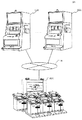
本実施形態の遊技機200の概観を図7に示す。
【0086】
遊技機200は、競馬ゲームを行うための遊技機であり、概観上、遊技処理を行う装置と、遊技に関する画像を表示する表示装置と、を備えた筐体299と、前記筐体299と対向して設置され、複数の遊技者に対し操作可能な操作部を提供する操作端末であって、筐体299と通信可能な状態に接続された複数の操作端末298と、から構成される。
【0087】
遊技機200の本体を構成している筐体299の正面には、略矩形の表示装置216が備えられている。この表示装置は、液晶表示器とするが、本発明はこれに限らず、例えば、CRTディスプレイ、ELディスプレイ、プラズマディスプレイ等であってもよい。
【0088】
この表示装置216は、競馬ゲームに関する画像、例えば馬券配当率状況(所謂オッズ)や、競馬のレース実況や、競馬のレース結果等が表示され、操作端末298で遊技に関する操作を行う複数の遊技者に対し、競馬ゲームに関する遊技画像を視認せしめるものである。
【0089】
遊技機200の本体を構成している筐体299の上部には、2個のスピーカ214(214L、214R)が備えられている。このスピーカは、操作端末298で遊技に関する操作を行い遊技に参加している遊技者に対し、遊技の演出を行う音声を発するものである。
【0090】
なお、表示装置216に表示される表示画像は、画像データとしてネットワークN(図1参照)を介して遊技機200から遊技機100へ送信され、遊技機100側で、制御回路131(図6参照)を構成する通信制御回路135(図6参照)が当該画像データを受信して液晶表示器138(図6参照)に表示する表示画像と同一の画像である。
【0091】
なお、本実施形態では、遊技機200は、表示装置216を液晶表示器とし、この液晶表示器に、予めROM203に記憶された画像データから合成された競馬のレース実況や競馬のレース結果等の画像を表示するとしている。本発明では、これに限定されず、競馬場の模型を設けて模型の馬を競走させる構成を追加させてもよい。この場合、遊技機200の表示装置216及び遊技機100の液晶表示器138に表示させる競馬のレース実況の画像表示は、予めROM203に記憶された画像データから合成した画像を表示する手段によるものでも、CCDカメラ等により模型のレース場での模型の馬の競走を撮影した画像を表示する手段によるものでも、いずれでもよい。
【0092】
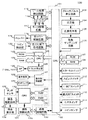
[遊技機200の電気的構成]
図8は、遊技機200のハードウェアブロック図である。
【0093】
図8の破線で囲まれた部分は、遊技機200の主制御回路201である。第二の遊技制御手段を構成する主制御回路201は、予め設定されたプログラムに従って制御動作を行うCPU202と、記憶手段であるROM203及びRAM205と、通信制御回路218を含むものである。
【0094】
ROM203には、遊技機200の遊技全体の流れを制御する制御プログラムと、遊技に関する画像データと、を記録する。また、ROM203は、制御プログラムを実行するための初期データや、表示装置216における表示制御を行うプログラム等を記憶する。更には、各種周辺機器に対して信号を送信するための各種制御指示(コマンド)等が格納されている。
【0095】
なお、本実施形態でのプログラムはROM203に記録されていたが、本発明はこれに限らず、CPU202に各種処理を、手順、手段、機能として実行させることができ、CPU202に接続された各種読み取り装置により読み取り可能な記録媒体であればよく、例えばハードディスク装置、CD−ROM及びDVD等の記憶媒体に記録されていてもよい。また、これらのプログラムは、予め記録されているものでなくとも、電源投入後にRAM205等に記録されるものでもよい。更にまた、プログラムの各々が別々の記憶媒体に記録されていてもよい。
【0096】
RAM205は、前述したプログラムで使用するフラグや変数の値を一時記憶する。
【0097】
CPU202には、所定のインターフェイス回路群(図示せず)を介して、各種の周辺機器が接続されている。
【0098】
CPU202には、乱数サンプリング回路209が接続されている。
【0099】
乱数サンプリング回路209には、乱数発生器208が接続されており、乱数発生器208で一定の周期で発生される乱数が、乱数サンプリング回路209によりサンプリングされ、当該乱数の情報がCPU202に供給される。
【0100】
なお、乱数発生器208において一定の周期により乱数を発生させるために、乱数発生器208に一定周期のパルスを供給するため、乱数発生器208に分周器207が接続され、分周器207にはクロックパルス発生回路206が接続されている。このような構成をとり、クロックパルス発生回路206にて、遊技機200の主制御回路201とは独立したパルスを以って乱数を発生させる。クロックパルス発生回路206が、遊技機200の主制御回路201とは独立した周期を持つパルスを発生させ、そのパルスを分周器207に入力して分周し、その分周されたパルスに基づき乱数発生器208で乱数を発生させるのである。
【0101】
なお、本実施形態では、遊技機200は乱数発生器208を備えた構成をとり、その乱数発生器208から発生された乱数をCPU202がRAM205に記憶させるとしたが、本発明はこれに限らず、CPU202が、ROM203に記録されたプログラムに基づいて乱数を発生させるようにしてもよい。
【0102】
また、CPU202には、サウンドCPU210が接続されている。このサウンドCPU210は、CPU202から供給される音声発生指示信号を受け取ることにより、スピーカ214から音声を発生させる。
【0103】
また、サウンドCPU210には、ROM211、RAM212、及びサウンド発生部213が接続されている。更に、サウンド発生部213には、スピーカ214(214L及び214R)が接続されている。
【0104】
このROM211には、音声データが記憶されており、サウンドCPU210は、前述した音声発生指示信号を受け取ることにより、その信号に基づいた音声データをROM211から読み出す。なお、サウンドCPU210は、CPU202から供給されたデータや、ROM211から読み出した音声データをRAM212に一時記憶させる。更に、サウンドCPU210は、読み出した音声データを所定のタイミングでサウンド発生部213に供給し、このサウンド発生部213が音声データを所定の信号に変換し、スピーカ214に供給することにより、音声が発生する。
【0105】
また、CPU202には、表示制御装置215が接続されている。この表示制御装置215は、CPU202から供給された画像表示指示信号を受け取ることにより、その表示制御装置215に接続された表示装置216、各種ランプ217を制御する。各種ランプ217とは、遊技機200の筐体299に備えられ、遊技(競馬ゲーム)に関する各種演出を行うランプ群の総称である。
【0106】
また、CPU202には、通信制御回路218が接続されている。この通信制御回路218は、遊技機100の第二の遊技(競馬ゲーム)の制御回路131を構成する通信制御回路135と通信を行い、第二の遊技の制御回路131との間で、第二の遊技(競馬ゲーム)における遊技に関する各種情報(遊技画像情報、BET情報、遊技抽選結果情報、配当決定情報)の送受信を行う。
【0107】
また、前記通信制御回路218は、操作端末298の制御回路(図示せず)を構成する通信制御回路(図示せず)と通信を行い、当該制御回路との間で、競馬ゲームにおける遊技に関する各種情報(遊技画像情報、BET情報、遊技抽選結果情報、配当決定情報)の送受信を行う。
【0108】
[遊技機の動作]
先ず、遊技機100の主制御回路において実行されるBET処理を制御するサブルーチンを図9に示す。
【0109】
なお、本サブルーチンは、遊技機100において、遊技者により第一の遊技(スロット)及び第二の遊技(競馬ゲーム)のBET時に呼び出される処理である。
【0110】
このように、第一の遊技(スロット)と第二の遊技(競馬ゲーム)において、BET処理を共通化するのは、遊技機100において、コインのBET及び払出しに関してホッパーを共有化し、コインを共用するためである。すなわち、遊技者により遊技機100に投入された若しくはCREDITされたコインは、第一の遊技及び第二の遊技いずれにおいてもBET可能であり、第一の遊技または第二の遊技を問わず、配当が付与されコインが払出される場合は、ホッパーを共用してコインが払出されるためである。
【0111】
図9を参照して、ステップS11で、コインの投入があったか否かを判定する。この処理で、遊技機100のコインセンサ114(図6参照)が、遊技者によるコインの投入を検知したときに、検知信号をCPU102へ供給する。コインセンサ114がコインの投入を検知した場合はステップS12へ処理を移し、コインセンサ114がコインの投入を検知しない場合はステップS16へ処理を移す。
【0112】
次に、ステップS12では、投入コイン数データ加算処理を行う。この処理で、遊技機100のCPU102は、RAM108に配置された投入コイン数のデータを格納する変数をインクリメント(1を加算)する。この処理が終了すると、ステップS13へ処理を移す。
【0113】
次に、ステップS13では、ステップS12で記憶された投入コイン数データを参照して、BET数の上限を超過しているか否かの判定を行う。この処理で、遊技機100のCPU102は、ROM107に記録されたBET数上限値をRAM108へ読み出し、RAM108に記憶された投入コイン数データとの比較を行い、投入コイン数データがBET数上限値を超過していると判定される場合はステップS15へ処理を移す。一方、投入コイン数データがBET数上限値を超過していると判定されない場合は、ステップS14へ処理を移す。
【0114】
次に、ステップS14では、BET数データ加算処理を行う。この処理で、遊技機100のCPU102は、RAM108に配置されたBET数データを格納する変数をインクリメントする。この処理が終了すると、ステップS16へ処理を移す。
【0115】
一方、ステップS15では、CREDIT数データ加算処理を行う。この処理では、ステップS13でBET数上限を超過していると判定された投入コインについて、CREDIT数への加算処理を行う。遊技機100のCPU102は、RAM108に配置されたCREDIT数データを格納する変数をインクリメントする。この処理が終了後、ステップS16へ処理を移す。
【0116】
次に、ステップS16では、BET操作されたか否かの判定を行う。この処理では、遊技機100のスピンスイッチ110(図6参照)または1−BETスイッチ111または最大BETスイッチ112のいずれかのスイッチが遊技者により操作され、CPU102に対し操作信号が供給された場合ステップS17へ処理を移し、一方、操作信号が供給されなかった場合直ちに本サブルーチンを終了する。
【0117】
次に、ステップS17では、CREDIT数が無い、または、BET数上限超過のいずれかの条件に該当するかの判定を行う。この処理では、遊技機100のCPU102が、RAM108に配置されたCREDIT数データを格納する変数及びBET数データを格納する変数を参照して、CREDIT数が「0」またはBET数データが上限超過していると判定する場合は直ちに本サブルーチンを終了し、一方判定しない場合はステップS18へ処理を移す。
【0118】
次に、ステップS18では、BET数データの加算処理を行う。この処理では、遊技機100のCPU102が、RAM108に配置されたBET数データを格納する変数をインクリメントする。この処理が終了すると、ステップS19へ処理を移す。
【0119】
次に、ステップS19では、CREDIT数減算処理を行う。この処理では、遊技機100のCPU102が、RAM108に配置されたCREDIT数データを格納する変数をデクリメント(1を減算)する。この処理が終了すると、本サブルーチンは終了する。
【0120】
[スロット遊技処理]
次に、遊技機100の主制御回路において実行されるスロット遊技処理を制御するサブルーチンを図10に示す。
【0121】
図10を参照して、ステップS21では、BET数データが「0」であるか否かを判定する。この処理において、遊技機100のCPU102は、RAM108に記憶されたBET数データを読み出し、そのBET数データが「0」であると判定した場合には、再度、ステップS21に処理を移し、そのBET数データが「0」であるとは判定しなかった場合には、ステップS22に処理を移す。
【0122】
次に、ステップS22では、遊技開始の操作がなされたか判定する。この処理において、遊技機100のCPU102は、スタートスイッチ109から供給されるスタート信号を受け取ったか否かを判定することとなる。この結果、CPU102は、スタート信号を受け取ったと判定した場合には、ステップS23に処理を移し、スタート信号を受け取ったとは判定しない場合には、ステップS21に処理を戻す。これにより、スタートレバー196(図2参照)が操作されるまでは遊技を開始しない。
【0123】
次に、ステップS23では、乱数抽選処理を実行する。この処理において、抽選される乱数により、後述するステップS24のリール回転停止処理での回転速度、停止図柄が決定される。本実施形態では、遊技機100の乱数発生器105は0〜16383(=214通り)の範囲の乱数を発生させて乱数サンプリング回路106が一乱数をサンプリングし、サンプリングした乱数をCPU102へ供給し、CPU102はRAM108に配置された変数にその乱数及びその乱数に基づいた内部抽選データを記憶させる。この処理が終了した場合には、ステップS24に処理を移す。
【0124】
次に、ステップS24では、リール回転停止処理を実行する。この処理において、遊技機100のCPU102は、モータ駆動回路117(図6参照)に対して駆動制御命令を行う。また、この処理は、ステップS23の処理によりRAM108に記録された内部抽選データに基づいて、その回転速度、停止図柄等が決定しており、そのリール197L、197C、197R(図2参照)が停止した場合には、ステップS25に処理を移す。
【0125】
なお、遊技機100のCPU102は、ステップS23の処理によりRAM108に記録された内部抽選データに基づいて、表示窓198L、198C、198R(図2参照)に所定の図柄が表示されるようにリール197L、197C、197Rを停止させる。
【0126】
次に、ステップS25では、入賞有りか否かを判定する。この処理において、遊技機100のCPU102は、有効ラインに停止表示されたリール197L、197C、197Rの図柄が、図4に示した如く、内部当選した役の入賞成立を示す停止態様であると判定した場合には、ステップS26に処理を移し、有効ラインに停止表示されたリール197L、197C、197Rの図柄が、内部当選した役の入賞成立を示す停止態様であるとは判定しない場合には、ステップS29に処理を移す。
【0127】
次に、ステップS26では、配当数データの算出処理を実行する。この処理では、遊技機100のCPU102は、有効ラインに停止表示されたリール197L、197C、197Rの図柄を検出し、図4に示す如く、配当数データを算出し、その旨のデータをRAM108に記録する。この処理が終了した場合には、ステップS27に処理を移す。
【0128】
次に、ステップS27では、配当処理を実行する。この処理では、遊技機100のCPU102は、ステップS26の処理によりRAM108に記録された配当数データに基づいて、クレジット数データを増加更新する、または、ホッパー駆動回路118(図6参照)に払出し指示信号を供給することにより、所定個数のコインの払出しを行う。その際、コイン検出部121(図6参照)は、ホッパー119から払い出されるコインの枚数を計数し、その計数値が指定された数に達したときに、コイン払出し完了信号がCPU102に供給される。この処理が終了した場合には、ステップS28に処理を移す。
【0129】
次に、ステップS28では、配当累積データの累積記録処理を実行する。この処理では、遊技機100のCPU102は、ステップS26の処理によりRAM108に記録された配当数データを読み出し、RAM108に配置された配当累積データを格納する変数へ加算する。この処理が終了した場合には、ステップS29に処理を移す。
【0130】
次に、ステップS29では、C/Pスイッチ113(図6参照)の押下の判定を行う。この処理では、遊技機100のC/Pスイッチ113が操作され、操作信号が遊技機100のCPU102に供給された場合は、CREDITされたコインの払出しを行って本サブルーチンの処理を終了し、一方操作信号がCPU102に供給されなかった場合はステップS21へ処理を戻す。
【0131】
[第二の遊技に関する遊技データ及び画像データの送受信処理]
次に、遊技機100と、遊技機200との間で通信を行い、第二の遊技に関する遊技データ及び画像データの送受信処理を制御するサブルーチンを図11に示す。
【0132】
本サブルーチンで送受信処理される遊技データ及び画像データの一例を図15に示す。
【0133】
なお、この処理は、後述するように、遊技機100において第二の遊技(競馬ゲーム)のBET操作が可能である間、遊技機200のCPU202が制御するタイマにより一定時間の間隔で実行されるサブルーチンである。
【0134】
また、図9に示すBET処理及び図10に示すスロット遊技処理とは独立したサブルーチンである。
【0135】
図11を参照して、ステップS31では、遊技機200が遊技機100に対して、遊技データ及び画像データを送信する処理を行う。遊技機200のCPU202が、タイマをカウントアップさせ、所定時間経過と判断したとき本サブルーチンが起動され、本ステップが実行される。この処理では、遊技機200のCPU202が、遊技機100に対し、通信制御回路218を介して、BET状況などの最新の遊技に関するデータ及び最新の遊技状況を表示するための画像データを信号化して送信する。この処理が終了すると、遊技機200側での処理は終了し、タイマのカウンタをクリアして再びタイマのカウントアップを開始する。
【0136】
一方、ステップS32では、遊技機100側で、ステップS31で遊技機200から送信された信号を受信する処理を行う。この処理では、遊技機100の第二の遊技の制御回路において、通信制御回路135を介してCPU132が前記信号の受信を検知した場合ステップS33へ処理を移す。
【0137】
次に、ステップS33では、ステップS32で受信した受信信号に基づき、遊技に関するデータ及び画像データを表示する処理を行う。この処理では、遊技機100の第二の遊技の制御回路のCPU132が、液晶駆動回路137に前記受信信号を供給する。当該受信信号を受信した液晶駆動回路137は、受信信号を液晶表示器138に表示可能な信号に変換した信号を液晶表示器138に供給し、液晶表示器138で当該供給信号に基づく画像を表示する。この処理が終了すると、本サブルーチンが終了する。
【0138】
[第二の遊技に関するBETデータの送受信処理]
次に、遊技機100と、遊技機200との間で通信を行い、第二の遊技に関するBETデータの送受信処理を制御するサブルーチンを図12に示す。
【0139】
本サブルーチンでは、遊技機100における第二の遊技において、遊技者によりBETされる処理を示すサブルーチンである。
【0140】
このサブルーチンは、図10に示すスロット遊技処理及び図11に示す遊技データ及び画像データの送受信処理とは独立したサブルーチンであり、遊技者によるBET操作を遊技機100及び遊技機200において受け付けている限り実行可能なサブルーチンである。
【0141】
図12を参照して、ステップS41では、遊技機100が遊技機200に対して、BET数データを送信する処理を行う。この処理では、遊技機100の液晶表示器138における図15の如き表示画面に対し、遊技者がBET操作を行う、例えば、図15の操作表示部150及び156はいずれも遊技者によるBET数入力の操作を行う操作表示部であるが、これらの操作表示部に対し遊技者がBET数入力を行うべく触接すると、その操作がタッチセンサ136により検知され、検知信号が遊技機100の第二の遊技の制御回路131のCPU132へ供給される。遊技機100のCPU132が検知信号を供給された場合ステップS42へ処理を移し、検知信号を供給されなかった場合直ちに本サブルーチンを終了する。
【0142】
なお、前記遊技者によるBET数入力処理は、遊技機100に対してコインの投入された、またはCREDITが「0」でないことを前提として行われる処理である。
【0143】
次に、ステップS42では、BET処理を行う。この処理では、遊技機100のCPU102は図9で示したBET処理と同様のサブルーチンを呼び出して実行する。この処理が終了すると、ステップS43へ処理を移す。
【0144】
次に、ステップS43では、ステップS42で遊技者により入力されたBETデータを、遊技機200に対して送信する処理を行う。この処理では、ステップS42で遊技者がBETするべく入力したBET数を、遊技機100のCPU132が、通信制御回路135を介して遊技機200へ送信する処理を行う。この処理が終了すると、本サブルーチンでの遊技機100における処理は終了する。
【0145】
一方、遊技機200側では、ステップS44で、遊技機100から送信されてきたBETデータを受信する処理を行う。この処理では、遊技機200の通信制御回路218が、遊技機100から送信されてきたBETデータに関する信号の受信を検知し、当該受信信号をCPU202へ供給する処理を行う。この処理が終了すると、ステップS45へ処理を移す。
【0146】
次に、ステップS45では、遊技機200のCPU202が、ステップS44で受信したBETデータを、RAM205に配置されたBETデータを格納する変数へ記憶する。この処理が終了すると本サブルーチンは終了する。
【0147】
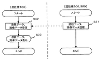
[第二の遊技の実行処理に関するデータの送受信処理]
次に、遊技機100と、遊技機200との間で通信を行い、第二の遊技の実行処理に関するデータの送受信処理を制御するサブルーチンを図13に示す。
【0148】
先ず、遊技機200側で、ステップS51において、BET受付終了通知情報送信処理を行う。この処理では、遊技機200のCPU202が、遊技機200で制御される第二の遊技の実行に際し、遊技機100からのBET操作を受け付けないようにする信号を、通信制御回路218を介して遊技機100に対して送信する。この処理が終了すると、遊技機200においてはステップS55へ処理を移す。
【0149】
一方、ステップS52では、遊技機200から送信されてきたBET受付終了通知情報の受信処理を行う。この処理では、遊技機100の通信制御回路135が、当該信号の受信を検知し、検知信号をCPU132へ供給する処理を行う。この処理の終了後、遊技機100においてはステップS53へ処理を移す。
【0150】
次に、ステップS53では、ステップS52でのBET受付終了通知情報の信号受信に基づき、遊技機100の液晶表示器138における操作表示部での一切の操作の受付を中止する処理を行う。この処理では、遊技機100のCPU132は、液晶駆動回路137に対し、液晶表示器138の操作表示部の操作受付を中止するよう信号を供給し、当該信号に基づき液晶駆動回路137は、液晶表示器138に対し操作表示部の操作受付が不可能となるように、液晶表示器138に対し画像信号を供給する。この処理が終了すると、ステップS54へ処理を移す。
【0151】
次に、ステップS54では、BET操作受付中止情報表示処理を行う。この処理では、ステップS53で実行されたBET操作受付中止処理に基づき、当該処理を行った旨を遊技機100の液晶表示器138に表示を行う。一例では、図15において表示部153において、「NOW BET」と表示されているときは、この画面からBET数入力操作可能であるが、ステップS54の処理により「NOW RACE」と表示されると、「現在レース中」を意味し、液晶表示器138から操作表示部150及び156からのBET数入力操作が不可能となっていることを示すことができる。この処理が終了すると、ステップS56へ処理を移す。
【0152】
一方、遊技機200においては、遊技機100におけるステップS54の処理の終了後に、ステップS55を実行する。すなわち、第二遊技実行処理を行う。この処理では、遊技機200のCPU202が制御を行う第二の遊技の実行処理を行う。第二の遊技が競馬ゲームの場合の処理は、後述する図14で示す第二遊技実行処理(競馬ゲーム)のサブルーチンで詳述する。この第二遊技実行処理のサブルーチンで第二の遊技(競馬ゲーム)の実行結果が得られ、当該実行結果と、各遊技者がBETしたBET情報に基づき付与される配当が決定され、遊技機100に対し、前記配当に関する情報の信号が送信される。この処理の終了後、遊技機200においてはステップS58へ処理を移す。
【0153】
一方、遊技機100においてはステップS56が実行され、遊技機200において実行されたステップS55で、遊技機200から送信されてきた配当に関する情報に基づき、配当の有無を判定する処理を行う。この処理では、遊技機100のCPU132が、RAM134に配置された配当に関する情報を格納した変数を参照して、配当の有無を判定する。配当が有りと判定される場合はステップS57へ処理を移し、配当が無しと判定される場合はステップS59へ処理を移す。
【0154】
次に、ステップS57では、ステップS56で配当ありと判定されたため、遊技者に対し配当を付与する配当処理を行う。この処理では、遊技機100のCPU132が、RAM134に配置された配当に関する情報を格納した変数を参照して、配当数を判定し、付与相当数のコインを払い出すべく、通信制御回路135を介して遊技機100の第一の遊技の主制御回路101に対して、コインの配当指示と配当枚数に関する信号を送信する。当該信号の受信を検知した遊技機100の第一の遊技の主制御回路101の通信制御回路130は、主制御回路101のCPU102に対し、コインの配当指示と配当枚数に関する信号を供給する。当該信号の供給を受けた遊技機100のCPU102は、CREDIT上限までCREDIT数を加算し、なお余りある配当に関してはホッパー駆動回路118にコインの払出しを指示する信号を供給し、ホッパー119は実際にコインの払出しを行う。このコインの払出しに対して、コイン検出部121は払出しコインの枚数をカウントし、所定払出し枚数に達したことを検知すると、当該検知信号を払出し完了信号回路120へ供給する。当該信号を供給された払出し完了信号回路120は、CPU102に対し払出しの停止信号を供給する。そして、払出しの停止信号を供給されたCPU102はホッパー駆動回路118に対してコインの払出しを停止する信号を供給し、当該信号を供給されたホッパー駆動回路118はホッパー119の駆動を停止し、コインの払出しが終了する。この処理が終了すると、ステップS59へ処理を移す。
【0155】
一方、遊技機200においては、遊技機100におけるステップS57の処理の終了後、ステップS58を実行する。この処理では、BET操作受付開始通知情報を送信する。すなわち、遊技機200における遊技の処理が終了したので、次の遊技の実行まで遊技機100の液晶表示器138の操作表示部150または156におけるBET操作を受け付けることができるようにする。遊技機200のCPU202は、遊技機100に対し通信制御回路218を介してBET操作受付開始通知情報の信号を送信する。この処理が終了すると、遊技機200における本サブルーチンの処理は終了する。
【0156】
一方、遊技機100において、ステップS59では、ステップS58で遊技機200から送信されてきたBET受付開始通知情報の受信処理を行う。遊技機100の通信制御回路135が当該情報信号の受信を検知すると、検知信号をCPU132へ供給する。この処理が終了すると、ステップS60へ処理を移す。
【0157】
次に、ステップS60では、BET操作受付開始処理を行う。この処理で、CPU132は当該信号に基づき液晶駆動回路137に対し、液晶表示器138に表示される操作表示部150または156の操作受付開始を指示する信号を供給する。当該指示信号の供給を受けた液晶駆動回路137は、液晶表示器138の操作表示部150または156の操作受付中止を解除する。この処理が終了すると、ステップS61へ処理を移す。
【0158】
次に、ステップS61では、BET操作受付開始表示処理を行う。この処理では、ステップS60で実行された液晶表示器138の操作表示部の操作受付中止解除処理にともない、当該処理が実行され、液晶表示器138の操作表示部のBET操作受付が可能であることを、液晶駆動回路137の供給する信号に基づき液晶表示器138に表示する。一例では、図15に示すような液晶表示器138の表示画面において、表示部153の表示を「NOW RACE」から「NOWBET」に変更することにより、液晶表示器138の操作表示部のBET操作受付が可能となったことを表示する。この処理が終了すると、本サブルーチンは終了する。
【0159】
[第二遊技実行処理及び当該処理に関するデータの送受信処理]
次に、遊技機100と、遊技機200との間で通信を行い、第二遊技実行処理及び当該処理に関するデータの送受信処理を制御するサブルーチンを図14に示す。
【0160】
図14を参照して、遊技機200において、先ずステップS71を実行する。この処理は、遊技機200における競馬ゲームの内部抽選処理である。RAM205に配置された変数に記憶された各遊技者のBET情報と、抽選される乱数に基づき、競馬のレース結果が決定される。本実施形態では、遊技機200の乱数発生器208は0〜16383(=214通り)の範囲の乱数を発生させて乱数サンプリング回路209が一乱数をサンプリングし、サンプリングした乱数をCPU202へ供給し、CPU202はRAM205に配置された変数にその乱数及びその乱数に基づいた内部抽選データを記憶する。この処理が終了した場合には、ステップS72に処理を移す。
【0161】
次に、ステップS72では、競馬のレース開始処理が実行される。ここで言う開始処理とは、競馬のレース結果はあくまでステップS71で決定されているので、ステップS72では、競馬レースの実況を想定して、レース実行状況の中継画像として遊技機100へ送信される画像をデータ化して、遊技機100に対して送信する準備を意味する。この処理では、遊技機200のCPU202が、ROM203に記録された画像データを読み出し、送信に適切な画像データを合成し、合成結果をRAM205に格納する処理を行う。この処理が終了すると、ステップS73へ処理を移す。
【0162】
次に、ステップS73では、レース状況情報送信処理を行う。この処理では、ステップS72で合成され記憶された、レース実況を表示するに適切な画像データを、遊技機100に対して連続送信する処理である。遊技機200のCPU202は、通信制御回路218を介して、RAM205に格納された当該画像データを、遊技機100に送信する処理を行う。この処理が終了すると、遊技機200においてはステップS76へ処理を移す。
【0163】
一方、遊技機100においてステップS74では、遊技機200から送信されてきた画像データを受信する処理を行う。この処理では、遊技機100の通信制御回路135が画像データの信号の受信を検知すると、CPU132に検知信号を供給する。この処理が終了すると、ステップS75へ処理を移す。
【0164】
次に、ステップS75では、遊技機100の通信制御回路135から検知信号の供給を受けたCPU132が液晶駆動回路137に対し、液晶表示器138への当該画像データに基づく表示を指示する信号を供給する。当該指示信号を供給された液晶駆動回路137は液晶表示器138に、当該画像データに基づく表示を行う。この処理が終了すると、遊技機100においては、ステップS80へ処理を移す。
【0165】
一方、遊技機200においては、ステップS76のレース終了か否かの判定を行う。CPU202がレース終了であるか否かを判定し、レース終了と判定する場合はステップS77へ処理を移し、レース終了と判定しない場合はステップS73へ処理を戻す。このようにして、全ての画像データを送信終了するまで、ステップS73の処理を継続する。
【0166】
次に、ステップS77では、レース終了処理を行う。この処理では、ステップS72で画像データの合成のために使用したRAM205に配置された変数の初期化及び記憶領域の初期化を行う。CPU202が、RAM205に配置された変数の初期化及び記憶領域の初期化を行う。この処理が終了すると、ステップS78へ処理を移す。
【0167】
次に、ステップS78では、配当数決定処理を行う。この処理では、ステップS71で決定されたレース結果に基づき、遊技機200のCPU202が各遊技者に対し付与する配当数を決定し、決定配当数をRAM205に配置された変数に記憶する。この処理が終了すると、ステップS79へ処理を移す。
【0168】
次に、ステップS79では、ステップS71で決定されたレース結果及びステップS78で決定された配当結果を、遊技機100に対し送信する処理を行う。この処理では、遊技機200のCPU202は、RAM205に配置されたレース結果及び配当結果に関する情報を格納した変数を読み出し、当該情報を、通信制御回路218を介して、遊技機100に対し送信する。この処理が終了すると、遊技機200においては、本サブルーチンは終了する。
【0169】
一方、遊技機100においてステップS80では、ステップS79で遊技機200が送信してきたレース結果及び配当結果の情報を受信する処理を行う。この処理では、遊技機100の通信制御回路135が当該情報の信号の受信を検知すると、CPU132に対し検知信号を供給する。この処理が終了すると、ステップS81へ処理を移す。
【0170】
次に、ステップS81では、ステップS80で受信したレース結果及び配当結果の情報を、遊技機100の液晶表示器138に表示する処理を行う。この処理では、レース結果及び配当結果の情報信号の検知信号を供給された遊技機100のCPU132が、液晶駆動回路137に対し当該受信信号に基づく表示を表示する指示の信号を供給する。当該信号を供給された液晶駆動回路137は、液晶表示器138に対し、レース結果及び配当結果の情報信号に基づく表示を表示する。この処理が終了すると、本サブルーチンが終了する。
【0171】
[遊技機100の第二の表示装置に表示される表示について]
図15は、遊技機の第二の表示装置、すなわち液晶表示器138に表示される第二の遊技(競馬ゲーム)の表示イメージである。
【0172】
操作表示部150は、各々の略矩形の操作表示部に触接することにより、遊技者が所望する勝ち馬投票を行うことができる。各々の略矩形の操作表示部に1回触接するごとに、各々のパターンの勝ち馬投票に際し、BETするコインの枚数が1枚ずつ増加するようになっている。「WIN」は単勝、「Quinella」は連勝複式、「Exacta」は連勝単式を表す。
【0173】
表示部151は、競馬のレース結果を表示する表示部である。この表示画面では6頭立ての競馬を行うので、1位から6位までの着順を馬番号で表示する。
【0174】
表示部152は、競馬レースが実行されているときのレース状況を実況する表示部である。レース実行中にこの表示部152に表示される表示画像は、図7の競馬ゲーム本体の表示装置216に表示される画像と同一である。
【0175】
表示部153は、「NOW BET」または「NOW RACE」のいずれかの表示を行い、「NOW BET」と表示されているときは、操作表示部150の操作が可能であり、「NOW RACE」と表示されているときは、表示部152にレース状況が表示され、操作表示部150の操作は不可となる。
【0176】
表示部154は、遊技機にCREDITされているコインの枚数を表示する。この表示は、遊技機100の表示装置128に表示されるCREDIT表示と一致する。
【0177】
表示部155は、レース結果により、この表示画面からBETして得た賞金の総額を表示する。
【0178】
操作表示部156は所謂「BOXBET」のための操作表示である。
【0179】
表示部157には、遊技者が操作表示部150または156を操作してBETしたコインの枚数の合計が表示される。
【0180】
以上のように遊技機を構成し、各遊技機に処理を行わせることによって、スロットの遊技者に対し、他の場所に設置された競馬ゲームの遊技機に移動することなくスロットを行っていた遊技機において競馬ゲームへ参加可能とすることができる。このことにより、スロットの遊技者の競馬ゲームへの参加が促進され、スロットの遊技者による遊技の選択性を向上させることになり、遊技場全体の稼働効率を高めることができる。また、より多くの遊技者に対し、競馬ゲームへの参加の機会を提供することができる。
【0181】
[第二の実施形態]
以下に、本発明の第二の実施形態について図面に基づいて説明する。
【0182】
第二の実施形態では、本発明の第一の遊技を「スロット」とし、第二の遊技を「ルーレット」ゲームとした場合を示す。
【0183】
[第二の実施形態のネットワーク構成図]
図16に示す遊技システムS2は、ネットワークNと、複数の遊技機100と、遊技機300と、から構成される。
【0184】
第二の実施形態における遊技機100及び遊技機300は、各遊技場に設置され、遊技者により遊技の操作が行なわれるものである。遊技機100は(第一の)実施形態と同様のスロットマシンであり、遊技機300は、複数人数が参加可能の一般的なルーレットゲームである。遊技機300の構成要素及び機能については後述する。
【0185】
[遊技機300の概観]
第二の実施形態の遊技機300の概観を図17に示す。
【0186】
遊技機300は、ルーレットゲームを行うための遊技機であり、ルーレット遊技を行う筐体399があって、前記筐体399は、ルーレット装置398と、ルーレット装置全景を上部から撮影するためのCCD(Change Coupled Device)カメラ313と、直近の所定回数(本実施形態では一例として5回)のルーレット遊技結果を表示する表示装置309と、から構成される。
【0187】
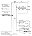
[遊技機300の電気的構成]
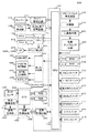
図18は、遊技機300のハードウェアブロック図である。
【0188】
図18の破線で囲まれた部分は、遊技機300の主制御回路301である。第二の遊技制御手段を構成する主制御回路301は、予め設定されたプログラムに従って制御動作を行うCPU302と、記憶手段であるROM303及びRAM304と、通信制御回路314を含むものである。
【0189】
ROM303には、遊技機300を制御する各種制御プログラムを記録する。また、ROM303は、制御プログラムを実行するための初期データや、表示装置309における表示制御を行うプログラム等を記憶する。更には、各種周辺機器に対して信号を送信するための各種制御指示(コマンド)等が格納されている。
【0190】
RAM304は、前述した各種制御プログラムで使用するフラグや変数の値を一時記憶する。
【0191】
CPU302には、所定のインターフェイス回路群(図示せず)を介して、各種の周辺機器が接続されている。
【0192】
CPU302にはインターフェイス回路群を介してルーレット始動スイッチ307が接続されている。これはルーレットのディーラにより操作され、スイッチ操作のタイミングでCPU302にルーレット始動信号が供給されるものである。
【0193】
また、CPU302にはインターフェイス回路群を介して表示制御装置308が接続されている。この表示制御装置308は、CPU302から供給された数値表示指示信号を受け取ることにより、その表示制御装置308に接続された表示装置309を制御する。
【0194】
また、CPU302にはインターフェイス回路群を介してルーレット駆動回路310が接続されている。このルーレット駆動回路310は、CPU302から供給されたルーレット駆動指示信号を受け取ることにより、そのルーレット駆動回路310に接続されたルーレット駆動モータ311を制御する。
【0195】
また、CPU302にはインターフェイス回路群を介してCCD制御回路312が接続されている。このCCD制御回路312は、CPU302から供給されたCCD制御信号を受け取ることにより、そのCCD制御回路312に接続されたCCD313を制御する。
【0196】
更にまた、CPU302にはインターフェイス回路群を介して球停止センサ315が接続されている。この球停止センサ315は、ルーレット装置の数値表示の近傍にある球停止のための各格子の底部に配置され、ルーレットの球が停止した位置の検出を行う装置である。ルーレットの球が停止した位置の検出を行い、その停止位置の情報をCPU302へ供給する装置である。
【0197】
なお、この球停止センサを備えない構成であってもよく、その場合は、たとえば、ルーレットのスピンにより球が回転し、球が停止した位置をディーラの目視により確認し、インターフェイス回路群を介して接続された球の停止番号を入力する入力装置から球の停止番号を入力する構成をとってもよい。
【0198】
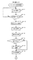
[遊技機の動作]
第二の実施形態の遊技機の動作は、第一の実施形態と同様であるが、図13における第二遊技実行処理で呼び出されるサブルーチンが異なるため、図19を参照して、第二遊技実行処理(ルーレットゲーム)の処理を説明する。
【0199】
先ず、遊技機300においてステップS91で、遊技機300のCPU302が、ディーラによりルーレット始動スイッチ307が操作され、その操作信号がCPU302に供給されたか否かの判定を行う。ディーラによりルーレット始動スイッチが操作され、その操作信号がCPU302に供給されたと判定する場合、ステップS92へ処理を移し、判定されない場合ステップS91を再実行する。
【0200】
次に、ステップS92では、スピン開始処理を行う。この処理では、CPU302にルーレット始動スイッチ307の操作信号が供給され、ルーレット駆動回路310がルーレット駆動モータ311を駆動し、スピンを開始する処理を行う。この処理が終了すると、ステップS93へ処理を移す。
【0201】
次にステップS93では、スピン状況画像情報送信処理を行う。この処理では、遊技機300のCPU302がCCD制御回路312に対しCCD313の撮影指示信号の供給を開始する。この信号を受信したCCD制御回路312は、CCD313に対し撮影指示信号の供給を開始し、当該信号を受信したCCD313は、ルーレット装置全景の撮影を開始する。CCD制御回路312を介して撮影データを供給されたCPU302はこの撮影データを信号化し、通信制御回路314を介して遊技機100に対して送信する。この処理が終了すると、遊技機300においては、ステップS95へ処理を移す。
【0202】
一方、遊技機100においてはステップS94で、遊技機300のステップS93で送信されたスピン状況画像情報受信処理を行う。この処理では、通信制御回路135(図6参照)が、当該信号の受信を検知し、検知信号をCPU132に供給する。この処理が終了すると、遊技機100においてステップS96へ処理を移す。
【0203】
次に、ステップS96では、スピン状況画像情報表示処理を行う。この処理では、ステップS94で受信したスピン状況画像情報に基づき、遊技機100のCPU132が液晶駆動回路137に対し画像表示信号を供給し、当該信号を供給された液晶表示器138は、当該情報に基づく画像を表示する。この処理が終了すると、遊技機100においてはステップS98へ処理を移す。
【0204】
一方、遊技機300においてステップS95では、球停止位置検知の処理を行う。遊技機300の球停止センサ315(図18参照)が、ルーレットの球の停止位置を検知する。この処理が終了すると、遊技機300においてはステップS97へ処理を移す。
【0205】
次に、ステップS97では、球停止位置情報、球停止状況画像情報送信処理を行う。この処理では、ステップS95で遊技機300の球停止センサ315が検知した球停止位置の情報の信号がCPU302に対し供給され、CCDカメラ313が撮影した球停止状況が撮影信号として、CCDカメラ制御回路312を介してCPU302に対し供給される。当該信号を供給されたCPU302は、通信制御回路314を介して遊技機100に対して当該信号を送信する。この処理が終了すると、遊技機300においては、ステップS100へ処理を移す。
【0206】
一方、遊技機100においてはステップS98で、遊技機300のステップS97で送信された球停止位置情報、球停止状況画像情報受信処理を行う。この処理では、通信制御回路135(図6参照)が、当該信号の受信を検知し、検知信号をCPU132に供給する。この処理が終了すると、遊技機100においてステップS99へ処理を移す。
【0207】
次に、ステップS99では、球停止位置情報、球停止状況画像情報表示処理を行う。この処理では、ステップS98で受信した球停止位置情報、球停止状況画像情報に基づき、遊技機100のCPU132が液晶駆動回路137に対し画像表示信号を供給し、当該信号を供給された液晶表示器138は、当該情報に基づく画像を表示する。この処理が終了すると、遊技機100においてはステップS101へ処理を移す。
【0208】
一方、遊技機300のステップS100では、ゲーム結果送信処理を行う。この処理において、球停止センサ315が検知した球の停止位置に関する情報及び配当数に関する情報の信号がCPU302に供給され、さらにその情報が表示制御装置308に供給され、遊技機300の表示装置309の最新球停止番号表示に表示されるともに、当該球の停止位置に関する情報及び配当数に関する情報の信号が遊技機100に対して送信される。この処理が終了すると、遊技機300においては、本サブルーチンは終了する。
【0209】
一方、遊技機100においてステップS101で、ゲーム結果受信処理を行う。この処理では、遊技機300のステップS100において遊技機100に対し送信してきた球停止位置に関する情報及び配当数に関する情報の信号を、遊技機100の通信制御回路135が受信し、その検知信号をCPU132に供給し、当該信号の供給を受けたCPU132は、通信制御回路135を介して遊技機100の第一の遊技の主制御回路101に対して配当に関する情報信号に基づいてCREDITの増減情報またはCREDIT上限を超える配当付与の場合には、ホッパー駆動回路118に対しコインの払出し指示の信号を供給する。当該信号を、通信制御回路130を介して受信した遊技機100の主制御回路101は、CPU102がホッパー駆動回路118に対しコイン払出し信号を供給し、当該コイン払出し信号を供給されたホッパー駆動回路118はホッパー119を駆動してコインの払出しを行う。コイン検出部121が所定の枚数のコインをカウントし、払出し完了信号回路120に払出し完了信号を供給し、当該払出し完了信号の供給を受けた払出し完了信号回路120がCPU102に対し払出し完了信号を供給し、CPU102が払出し完了信号の供給を受けホッパー駆動回路118に対し払出し完了信号を供給して、コインの払出しが終了する。また、CPU132は液晶駆動回路137に対し当該球停止位置に関する情報及び配当数に関する情報に該当する情報を液晶表示器138に表示するよう指示信号を供給し、また、配当数に関する情報に基づきCREDITの増減がある場合には、CREDIT情報を更新して、液晶駆動回路137に対し表示指示の信号を供給する。当該指示信号の供給を受けた液晶表示器138は、停止位置に関する情報、配当数に関する情報及び更新されたCREDIT情報を表示する。この処理が終了すると、本サブルーチンが終了する。
【0210】
[第二の実施形態において遊技機100の第二の表示装置に表示される表示について]
図20は、遊技機の第二の表示装置、すなわち液晶表示器138に表示される第二の実施形態における第二の遊技(ルーレットゲーム)の表示イメージである。
【0211】
操作表示部397は、コインをBETする実際のルーレット台に準じた升目表示である。操作表示部394に表示されたコインに一枚ずつ触接し、そのコインを操作表示部397で遊技者がBET所望の賭け位置までドラッグすることにより、BETするコインを遊技者がBET所望の賭け位置に置く、タッチパネル方式を採用している。
【0212】
表示部396は、CCD313により撮影された、実際のルーレット台のルーレットの全景画像である。ルーレットがスピンしている間、この部分にルーレットの最像画像が表示され、遊技者の目視により球の停止位置が確認可能となっている。
【0213】
表示部395は、「NOW BET」または「NOW SPIN」のいずれかの表示が表示される、「NOW BET」が表示されているときは、表示部396の表示は無く、遊技者によるBET操作が可能な状態であり、「NOW SPIN」が表示されているときは、表示部396の表示が現れ、遊技者によるBET操作が不可能な状態である。
【0214】
操作表示部394は、遊技者がコインをBETする場合、触接によりこの位置からコインを所望の賭け位置までドラッグするものである。
【0215】
表示部393は、遊技機にCREDITされているコインの枚数を表示する。この表示は、遊技機100の表示装置128に表示されるCREDIT表示と一致する。
【0216】
表示部392には、遊技者が操作表示部394及び397を操作してBETしたコインの枚数の合計が表示される。
【0217】
以上のように遊技機を構成し、各遊技機に処理を行わせることによって、スロットの遊技者に対し、他の場所に設置されたルーレットゲームの遊技台に移動することなくスロットを行っていた遊技機においてルーレットゲームへ参加可能とすることができる。このことにより、スロットの遊技者のルーレットゲームへの参加が促進され、スロットの遊技者による遊技の選択性を向上させることになり、遊技場全体の稼働効率を高めることができる。また、より多くの遊技者に対し、ルーレットゲームへの参加の機会を提供することができる。
【0218】
[第三の実施形態]
以下に、本発明の第三の実施形態について図面に基づいて説明する。
【0219】
第三の実施形態では、本発明の第一の遊技を「ビデオポーカ」とし、第二の遊技を「キノ」ゲームとした場合を示す。
【0220】
[第三の実施形態のネットワーク構成図]
図21に示す遊技システムS3は、ネットワークNと、複数の遊技機400と、遊技機500と、から構成される。
【0221】
第三の実施形態における遊技機400及び遊技機500は、各遊技場に設置され、遊技者により遊技の操作が行なわれるものである。遊技機400は一般的な「ビデオポーカ」マシンであり、遊技機500は、複数人数が参加可能の一般的な「キノ」ゲームである。それらの構成要素及び機能については後述する。
【0222】
[遊技機400の概観]
第三の実施形態の遊技機400の概観を図22に示す。
【0223】
遊技機400の全体を構成する筐体499には、主表示装置427が備えられている。
【0224】
この主表示装置427には、図22に示す様に5枚のトランプカードが区画に分かれて表示される。このトランプカードは、ポーカゲームのルールに則って、遊技開始時に全て裏向きの状態から始まり、ポーカゲームの進行に伴って順に表向きとして表示が行われる。
【0225】
この主表示装置427の画面内に、タッチパネル式の5個の「HOLD」(ホールド)操作表示部498が表示されている。
【0226】
この5個の「HOLD」操作表示部498は、主表示装置427に表示される5枚のトランプカードの区画それぞれの下方に対応して1個ずつ位置するように表示されている。
【0227】
この5個の「HOLD」操作表示部498が遊技者により触接されると、遊技機400のタッチセンサ450(図23参照)が触接を検知し、検知信号を遊技機400のCPU402に供給する。この5個の「HOLD」操作表示部498は、トランプカード配布時に、遊技者がホールド(交換しない)するカードを選択するときに用いられる。
【0228】
なお、本発明ではこの5個の「HOLD」操作表示部498はタッチパネル式に限らず、5個のスイッチを筐体499の前面に備えられた後述する各種スイッチの近傍に備えるようにしてもよい。
【0229】
また、主表示装置427の上方には、CREDIT数を表示するCREDIT数表示装置428及びBET数を表示するBET数表示装置429が備えられている。
【0230】
このCREDIT数表示装置428及びBET数表示装置429は、遊技者により遊技機400にCREDITされたコイン数と、BETコイン数を表示するものである。
【0231】
更にまた、CREDIT数表示装置428及びBET数表示装置429の上方には、第二の表示装置として液晶表示器449が備えられている。
【0232】
第三の実施形態では主表示装置427、CREDIT数表示装置428及びBET数表示装置429がLCDにより構成されるとするが、本発明における主表示装置427、CREDIT数表示装置428及びBET数表示装置429の種類はこれに限らず、CRT(Cathode Ray Tube)ディスプレイ、プラズマディスプレイ、7セグ、ドットマトリックス、ランプ、LED(Light Emitting Diode)、蛍光灯、EL(Electronic Luminescence)ディスプレイ、リール、ディスクなどを用い、1又は複数種類の表示装置を複数用いて構成してもよい。
【0233】
筐体499の最上方には、タワーライト494が設けられている。このタワーライト494は、所定のポーカの役が成立した場合に点灯するが、遊技機400のCPU402(図23参照)の制御のもと表示制御装置426(図23参照)により制御される各種ランプ430に含まれるランプ類の一種である。
【0234】
筐体499の前面には、遊技者によりポーカゲームに賭けるコインが投入されるコイン投入口497、前回遊技のBET数を記憶し、その記憶情報に基づいてBET数を設定するスピンスイッチ410、投入コイン又はCREDITコインのうちポーカゲームに賭けるコイン数を1枚ずつ設定する1−BETスイッチ411、同様に投入コイン又はCREDITコインのうちポーカゲームに賭けるコインを賭け数上限数に設定する最大BETスイッチ412、コインの賭け数が決まり、実際にポーカゲームをスタートするためのDEALスイッチ413、HOLD処理後にHOLDボタンが押下されていないカードを交換する処理を開始するDRAWスイッチ414、CREDITコインの払出しを指示するためのC/Pスイッチ415を備える。
【0235】
筐体499の前面下方には、スピーカ425(425R及び425L)が設けられている。このスピーカ425から所定の遊技演出のための音声が発生される。
【0236】
筐体499の前面最下方には、コインを払い出すためのコイン排出口496と、その払い出されたコインを受け取るための下皿495と、が設けられている。このコイン排出口496からは、クレジットが上限に至り、又は、C/Pスイッチ415が操作されたときにコインが排出される。
【0237】
[遊技機400の電気的構成]
図23は、遊技機400のハードウェアブロック図である。
【0238】
図23を参照して、遊技機400の制御構造は、大別して、第一の遊技(ビデオポーカ)を制御する主制御回路401と、第二の遊技(キノ遊技)の画像表示を制御する制御回路432と、から構成される。
【0239】
なお、遊技機400において、第一の遊技(ビデオポーカ)の制御は行うが、第二の遊技(キノ遊技)の遊技自体の制御は行わない。すなわち、第二の遊技の実行にかかる制御は遊技機500が行い、遊技機400の制御回路432は、遊技機500から、遊技に関する画像データと、BETに関するデータと、遊技機200における遊技結果と、に関する情報を受信して、かかる情報に基づいた情報を制御して表示するのみである。
【0240】
図23の破線で囲まれた第一の部分は、遊技機100の第一の遊技、すなわち「ビデオポーカ」遊技の主制御回路401である。主制御回路401は、予め設定されたプログラムに従って制御動作を行うCPU402と、記憶手段であるROM407及びRAM408と、通信制御回路431を含むものである。
【0241】
ROM407は、遊技機の遊技全体の流れを制御する制御プログラムを記録する。また、ROM407は、制御プログラムを実行するための初期データや、各種ランプ129の点滅動作パターンを制御するプログラムや、主表示装置427と、CREDIT数表示装置428と、BET数表示装置429と、における表示制御をするプログラム等を記憶する。更には、DEALスイッチ413またはDRAWスイッチ414を操作する毎に行われるサンプリング乱数の判定に用いられる確率抽選テーブル、そのサンプリング乱数に応じて主表示装置427に表示させる5枚のトランプカードの表示態様を決定するための表示制御テーブル、各種周辺機器に対して信号を送信するための各種制御指示(コマンド)等が格納されている。
【0242】
なお、本実施形態でのプログラムはROM407に記録されていたが、本発明はこれに限らず、CPU402に各種処理を、手順、手段、機能として実行させることができ、CPU402に接続された各種読み取り装置により読み取り可能な記録媒体であればよく、例えばハードディスク装置、CD−ROM及びDVD等の記憶媒体に記録されていてもよい。また、これらのプログラムは、予め記録されているものでなくとも、電源投入後にRAM408等に記憶されるものでもよい。更にまた、プログラムの各々が別々の記憶媒体に記録されていてもよい。
【0243】
RAM408では、前述したプログラム本体を実行時に記憶し、またプログラムで使用するフラグや変数の値を一時記憶する。
【0244】
CPU402には、所定のインターフェイス回路群(図示せず)を介して、各種の周辺機器が接続されている。
【0245】
CPU402には、乱数サンプリング回路406が接続されている。
【0246】
乱数サンプリング回路406には、乱数発生器405が接続されており、乱数発生器405で一定の周期で発生される乱数が、乱数サンプリング回路406によりサンプリングされ、当該乱数の情報がCPU402に供給される。
【0247】
なお、乱数発生器405において一定の周期により乱数を発生させるために、乱数発生器405に一定周期のパルスを供給するため、乱数発生器405に分周器404が接続され、分周器404にはクロックパルス発生回路403が接続されている。このような構成をとり、クロックパルス発生回路403にて、遊技機400の主制御回路401とは独立したパルスを以って乱数を発生させる。クロックパルス発生回路403が、遊技機400の主制御回路401とは独立した周期を持つパルスを発生させ、そのパルスを分周器404に入力して分周し、その分周されたパルスに基づき乱数発生器405で乱数を発生させるのである。
【0248】
なお、本実施形態では、遊技機400は乱数発生器405を備えた構成をとり、その乱数発生器405から発生された乱数をCPU402がRAM407に記憶させるとしたが、本発明はこれに限らず、CPU402が、ROM407に記録されたプログラムに基づいて乱数を発生させるようにしてもよい。
【0249】
また、コイン投入口497(図22参照)近傍に備えられたコインセンサ416がCPU402に接続されている。このコインセンサ416は、コイン投入口497からコインが投入されたことを検出する投入コイン算出信号をCPU402に供給する。
【0250】
更にまた、スピンスイッチ410と、1−BETスイッチ411と、最大BETスイッチ412と、がCPU402に接続されている。遊技者による、スピンスイッチ410、1−BETスイッチ411及び最大BETスイッチ412の操作に基づいて、BET信号をCPU402に供給する。
【0251】
なお、BETとは、遊技において「コインを賭ける」という意味を表す。
【0252】
また、CPU402には、DEALスイッチ413と、DRAWスイッチ414と、が接続されている。遊技者によりこれらのスイッチが押下されることにより、当該スイッチからCPU402に対してDEAL信号、またはDRAW信号が供給され、遊技者に配布されるトランプカードが決定され、主表示装置427に表示される。
【0253】
なお、ポーカゲームにおいて、DEALとは、最初のトランプカード配布の処理であり、DRAWとは、DEALされたトランプカードのうちHOLDされていないトランプカードを交換する処理である。
【0254】
更にまた、C/Pスイッチ415がCPU402に接続されている。C/Pスイッチ415は、遊技者の操作に基づいて、C/P信号をCPU402に供給する。
【0255】
更に、CPU402には、サウンドCPU421が接続されている。このサウンドCPU421は、CPU402から供給される音声発生指示信号を受け取ることにより、スピーカ425(425L、425R)から音声を発生させるものである。
【0256】
サウンドCPU421には、ROM422、RAM423及びサウンド発生部424が接続されている。更に、サウンド発生部424には、スピーカ425(425L、425R)が接続されている。
【0257】
このROM422には、音声データが記憶されており、サウンドCPU421は、前述した音声発生指示信号を受け取ることにより、その信号に基づいた音声データをROM422から読み出す。なお、サウンドCPU421は、CPU402から供給されたデータや、ROM422から読み出した音声データをRAM423に一時記憶させる。更に、サウンドCPU421は、読み出した音声データを所定のタイミングでサウンド発生部424に供給し、このサウンド発生部424が音声データを所定の信号に変換し、スピーカ425に供給することにより音声が発生する。
【0258】
更にまた、CPU402には、表示制御装置426が接続されている。この表示制御装置426は、CPU402から供給された画像表示指示信号を受け取ることにより、その表示制御装置426に接続された主表示装置427、CREDIT数表示装置428、BET数表示装置429、各種ランプ430を制御する。なお、この各種ランプ430には、タワーライト494(図2参照)が含まれている。
【0259】
また、CPU402には、ホッパー駆動回路417が接続されており、このホッパー駆動回路417には、ホッパー418が接続されている。内部当選した役の入賞成立を示す表示態様となれば、CPU402は、払出し指示信号をホッパー駆動回路417に供給してホッパー418から所定枚数のコインの払出しを行う。その際、コイン検出部420は、ホッパー418から払い出されるコインの枚数を計数し、その計数値が指定された数に達したときに、コイン払出し完了信号を払出し完了信号回路419へ供給し、払出し完了信号回路419がCPU402に対しコイン払出し完了信号を供給する。なお、本実施形態における遊技機400では、500枚のコインをクレジットすることができ、それ以上となった場合には、無条件で払出しが行われる。また、前述した如く、C/Pスイッチ415がC/P信号をCPU402に供給した場合にもコインの払出しが行われる。これにより、CPU402は、ホッパー駆動回路417を介してホッパー418の駆動を停止し、コインの払出し処理を終了する。
【0260】
また、CPU402には、通信制御回路431が接続されている。この通信制御回路431は、後述する第二の遊技(キノゲーム)の制御回路432を構成する通信制御回路446と通信を行い、後述するように、第二の遊技の制御回路432との間で、第二の遊技(キノゲーム)における遊技媒体の投入及び払出しに関する情報の送受信を行う。
【0261】
図23の破線で囲まれた第二の部分は、遊技機400の第二の遊技、すなわち「キノゲーム」遊技の画像表示のための制御回路432である。制御回路432は、通信制御回路446を介して、遊技機500から送信される制御情報に従って制御動作を行うCPU433と、記憶手段であるROM444及びRAM445と、通信制御回路446と、を含むものである。
【0262】
ROM444には、遊技機400の制御回路432に接続された接続機器、すなわちタッチセンサ447と、液晶駆動回路448と、液晶表示器449と、を制御する制御プログラム及び各種制御指示(コマンド)が記録されている。また、ROM444は、制御プログラムを実行するための初期データが記録されている。
【0263】
RAM445では、前述した制御プログラム本体を実行時に記憶し、また制御プログラムで使用する変数の値を一時記憶する。
【0264】
CPU433には、所定のインターフェイス回路群(図示せず)を介して、各種の周辺機器が接続されている。
【0265】
CPU433には、タッチセンサ447が接続されている。遊技者の操作により、後述する液晶表示器に表示された操作表示部が操作されると、タッチセンサ447はその操作を検知し、当該検知信号をCPU433に供給する。
【0266】
なお、本実施形態では、タッチセンサ447が「第二の遊技の遊技制御手段を操作する遊技操作手段」の一部を構成するが、本発明はこれに限らず、遊技者による操作をスイッチ等が検知し、当該検知信号をCPU433に供給することにより「第二の遊技の遊技制御手段を操作する遊技操作手段」を構成するようにしてもよい。
【0267】
また、CPU433には、液晶駆動回路448が接続されている。CPU433から液晶駆動回路448に対し、表示画像に関する情報の信号が供給されると、当該信号に基づき、後述する液晶表示器449に、表示画像の信号を供給する。
【0268】
前述の液晶駆動回路448には、液晶表示器449が接続されている。液晶駆動回路448から供給される表示画像にかかる信号を受信し、当該画像を表示するものである。
【0269】
なお、本実施形態では、液晶駆動回路448及び液晶表示器449を以って、第二の遊技の表示装置を構成するとしているが、本発明はこれに限らず、例えば、CRT(Cathode Ray Tube)ディスプレイ、EL(Electronic Luminescence)ディスプレイ、プラズマディスプレイ等を以って表示装置を構成してもよい。
【0270】
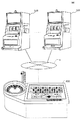
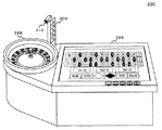
[遊技機500の概観]
第三の実施形態の遊技機500の概観を図24に示す。
【0271】
遊技機500は、キノゲームを行うための遊技機であり、キノの抽選を行う抽選筐体590があり、この抽選筐体590とは電気的に独立した7セグメントディスプレイにより構成された表示装置508と、表示装置508と電気的に接続された数字入力装置595と、の3つの部分から構成される。
【0272】
なお、前記表示装置508は、内部に図25の主制御回路501に相当する機器を備える筐体の役目も持っている。
【0273】
前記抽選筐体590は、ガラス容器に1から80の数字が書かれた球589が入っており、電気的にガラス容器内で球を自動的に攪拌する攪拌棒591により攪拌した球を、球取り出し口592から人手を介して1つずつ抽選し、合計20個の球を抽選する。その抽選の都度、球に書かれた数字に該当する数字入力装置595の数字入力スイッチ594を操作する。ケーブル596により電気的に数字入力装置595と接続された表示装置508には、1から80までの数字を表示する当選数字表示部599が備えられており、数字入力装置595で入力された数値に該当する数字の当選数字表示部599が点灯して数字を表示する仕組みになっている。なお、抽選された球は、球固定孔593に、数字が手前に目視可能になるように、1個ずつ合計20個を、固定していく。
【0274】
また、表示装置508には、現在の賞金の金額を表示する賞金表示部598が備えられている。
【0275】
[遊技機500の電気的構成]
図25は、遊技機500のハードウェアブロック図である。
【0276】
図25の破線で囲まれた部分は、遊技機500の主制御回路501である。第二の遊技制御手段を構成する主制御回路501は、予め設定されたプログラムに従って制御動作を行うCPU502と、記憶手段であるROM503及びRAM504と、通信制御回路509を含むものである。
【0277】
ROM503には、遊技機500を制御する各種制御プログラムを記録する。また、ROM503は、制御プログラムを実行するための初期データや、表示装置508における表示制御を行うプログラム等を記憶する。更には、各種周辺機器に対して信号を送信するための各種制御指示(コマンド)等が格納されている。
【0278】
RAM504は、前述した各種制御プログラムで使用するフラグや変数の値を一時記憶する。
【0279】
CPU502には、所定のインターフェイス回路群(図示せず)を介して、各種の周辺機器が接続されている。
【0280】
CPU502にはインターフェイス回路群を介して数字入力スイッチ594が接続されている。これはキノのディーラにより操作され、スイッチ操作のタイミングでCPU502に数字表示信号が供給されるものである。
【0281】
また、CPU502にはインターフェイス回路群を介して表示制御装置507が接続されている。この表示制御装置507は、CPU502から供給された数値表示指示信号を受け取ることにより、その表示制御装置507に接続された表示装置508を制御する。
【0282】
[遊技機400の動作]
上述した遊技機400の主制御回路401において実行される遊技機400を制御するドローポーカ処理を図26及び図27に示す。
【0283】
なお、遊技機400において以下の処理を行う前に、遊技機400の電源が投入され、主処理を実行するプログラムがRAM408にロードされ、RAM408に格納された各変数は初期化されているものとする。
【0284】
図26に示す如く、ステップS111では、BET処理を行う。この処理では、図9に示すBET処理と同様のサブルーチンが呼び出される。この処理により、遊技者により遊技機400へBETするコイン数が決定される。この処理の終了後、ステップS112へ処理を移す。
【0285】
ステップS112では、BET数の判定処理を行う。この処理により、遊技者の操作によりBETされたコイン数が1以上であるか否かの判定をする。CPU402が、BET数が1以上であるかと判定する場合はステップS113に処理を移し、一方判定しない場合はステップS111へ処理を戻す。
【0286】
次に、ステップS113は、遊技者によるDEALスイッチの押下操作の検知処理である。この処理により、遊技者によりDEALスイッチが押下されたことを遊技機400のDEALスイッチ413が検知し、検知信号がCPU402に供給される。この処理の終了後、ステップS114へ処理を移す。
【0287】
次に、ステップS114では、DEAL処理を行う。この処理により、遊技機400のCPU402が、遊技者に対し5枚のカードを配布する。この処理の終了後、ステップS115へ処理を移す。
【0288】
次に、ステップS115では、1回目の役判定処理を行う。この処理により、遊技機400のCPU402が、遊技者に対し1回目に配布された5枚のカードの組み合わせが、ポーカ役に相当するか否かの判定を行う。この処理の終了後、ステップS116へ処理を移す。
【0289】
次に、ステップS116では、HOLDスイッチ押下操作が行なわれる。遊技者によりステップS114で配布された5枚のカードのうち、HOLDするカードが決定され、HOLDするカードに相当する「HOLD」操作表示部498に触接された場合、タッチセンサ450が触接信号を検知し、信号がCPU402に供給され、CPU402が当該信号を受信した場合には、CPU402はステップS117へ処理を移し、HOLDするカードに相当する「HOLD」操作表示部498に触接されなかった場合にはステップS118へ処理を移す。
【0290】
次に、ステップS117では、カードHOLD処理を行う。この処理では、ステップS116でのCPU402の信号検知に基づき、カードのHOLD処理を行う。この処理の終了後、ステップS118へ処理を移す。
【0291】
次に、ステップS118では、DRAW処理が行なわれる。この処理により、遊技機400のCPU402が、ステップS117でHOLDされたカード以外のカードの交換を行う。この処理の終了後、ステップS119へ処理を移す。
【0292】
図27に示す如く、ステップS119では、2回目の役判定処理を行う。この処理により、遊技機400のCPU402が、遊技者に対しステップS118でカードの交換が行われた後の5枚のカードの組み合わせが、ポーカ役に相当するか否かの判定を行う。この処理はステップS115と同様である。この処理の終了後、ステップS120へ処理を移す。
【0293】
次に、ステップS120は、ステップS115又はステップS119の役判定処理の結果を判定する処理を行う。この処理により、遊技機400のCPU402が、ステップS115又はステップS119の役判定処理の結果がポーカ役に相当すると判定する場合はステップS121へ処理を移し、判定しない場合はステップS127へ処理を移す。
【0294】
次に、ステップS121は、遊技者による「DOUBLE UPゲーム」を行うかの判定処理である。「DOUBLE UPゲーム」とは、或る役が成立し遊技者に対し相当する配当が付与された後、その獲得配当を賭けて行う勝負のことである。遊技機400のCPU402により制御されるディーラと遊技者により、1枚ずつトランプカードが引かれ、そのカードの優劣により勝敗を決定するもので、遊技者のカードが勝っていた場合には遊技者の獲得配当は2倍になり、遊技者のカードが劣っていた場合には遊技者の獲得配当は0になるものである。この「DOUBLE UPゲーム」を行うか否かの決定は遊技者にゆだねられ、操作部の操作により、遊技者が「DOUBLE UPゲーム」を行うと判定される場合はステップS122へ処理を移し、一方判定されない場合はステップS126へ処理を移す。
【0295】
次に、ステップS122では、DOUBLE UPゲーム処理を行う。この処理の終了後、ステップS123へ処理を移す。
【0296】
次に、ステップS123では、ステップS122のDOUBLE UPゲーム結果を判定する処理を行う。この処理では、遊技機400のCPU402がステップS122のDOUBLE UPゲーム結果を判定し、遊技者の勝ちの場合はステップS124へ処理を移し、遊技者の負けの場合は、ステップS125へ処理を移し、引き分けの場合にはステップS121へ処理を戻す。
【0297】
次に、ステップS124では、ステップS123のDOUBLE UPゲームで遊技者の勝ちであったため、遊技機400のCPU402は遊技者の配当を2倍にする処理を行う。この処理の終了後、ステップS121へ処理を戻す。
【0298】
また、ステップS125では、ステップS123のDOUBLE UPゲームで遊技者の負けであったため、遊技機400のCPU402は遊技者の配当を0にする処理を行う。この処理の終了後、ステップS127へ処理を移す。
【0299】
一方、ステップS126では、配当払出し処理を行う。遊技者に対しポーカ役成立により相当する配当を付与するため、遊技機400のCPU402は配当に相当するコインをクレジットし、最大クレジット枚数を超過するコインは、ホッパー駆動回路417にコイン払出し信号を供給し、その信号を受信したホッパー駆動回路417はホッパー418を駆動しコインの払出しを、コイン排出口496より行う。このとき、コイン検出部420は、コイン排出口496より払出されるコインの枚数を計数し、所定の枚数に達したと検知した場合に、払出し信号完了回路419にコインの払出しを停止する信号を供給し、払出し信号完了回路419はCPU402に対し、コインの払出しを停止する信号を供給する。当該信号を供給されたCPU402は、ホッパー駆動回路417に対し、コインの払出しを停止する信号を供給する。この処理の終了後、ステップS127へ処理を移す。
【0300】
次に、ステップS127では、各種変数初期化処理を行う。遊技機400のCPU402は、RAM408に配置された各種変数の初期化を行う。この処理の終了後、本ルーチンが終了する。
【0301】
[遊技機500の動作]
第三の実施形態の遊技機500の動作は、第一及び第二の実施形態と同様であるが、図13における第二遊技実行処理で呼び出されるサブルーチンが異なるため、図28を参照して、第二遊技実行処理(キノゲーム)の処理を説明する。
【0302】
先ず、遊技機500においてステップS131で、ディーラによりキノ抽選を開始する場合ステップS132へ処理を移し、開始されない場合ステップS131を再実行する。
【0303】
次に、ステップS132ではディーラによるキノ抽選を行う。この処理の終了後、ステップS133へ処理を移す。
【0304】
次に、ステップS133では、抽選された球の番号を入力する処理を行う。キノのディーラにより、数字入力装置595の数字入力スイッチ594が操作され、操作された数字のスイッチに該当する、表示装置508の当選数字表示部599が点灯される。この処理の終了後、ステップS134へ処理を移す。
【0305】
次に、ステップS134では、ステップS133で入力され、表示装置508の当選数字表示部599に点灯された球の番号の情報を信号化して、遊技機400へ送信する処理を行う。遊技機500のCPU502は、当該球の番号の情報を信号化し、通信制御回路509を介して、遊技機400に対し送信する。この処理の終了後、遊技機500においてはステップS136へ処理を移す。
【0306】
一方、遊技機400のステップS135では、遊技機500のステップS134で送信されてきた球の番号の情報の信号を受信する処理を行う。遊技機400の通信制御回路446が、当該信号の受信を検知すると、検知信号をCPU433へ供給する。この処理が終了すると、遊技機400においてはステップS137へ処理を移す。
【0307】
次に、ステップS137では抽選されたボールの番号の表示処理を行う。この処理では、ステップS135でCPU433に供給された、球の番号の情報の信号の検知信号に基づき、CPU433は液晶駆動回路448に対し当該情報の表示指示信号を供給し、当該指示信号を供給された液晶駆動回路448は、液晶表示器449において、抽選されたボールの番号の表示処理を行う。この処理が終了すると、遊技機400においては、本サブルーチンの処理が終了する。
【0308】
一方、遊技機500のステップS136では、キノの抽選が20回に達しているかの判定を行う。すなわち、キノ抽選が20回に達するまで、ステップS132からステップS134の処理を繰り返す。キノ抽選が20回に達したならば、本サブルーチンを終了する。
【0309】
[第三の実施形態において遊技機400の第二の表示装置に表示される表示について]
図29は、遊技機の第二の表示装置、すなわち液晶表示器449に表示される第三の実施形態における第二の遊技(キノゲーム)の表示イメージである。
【0310】
操作表示部456は、遊技者が選択するキノの数字を表示する表示部である。遊技者は、選択したい番号の区画に触接することにより、選択された数字の区画に「チェックマーク」が表示される。また、キノの抽選が行われ、当選番号となった数字の区画は反転表示され、他の区画と識別できるように表示される。
【0311】
操作表示部451は、キノにおける各種BET方法を選択する触接部である。遊技者が選択したいBET方法に該当する操作表示部に触接し、該当操作表示部の表示を反転表示させた状態において、そのBET方法が有効となる。
【0312】
表示部452は、遊技者により選択された数字の個数を表示する表示部である。
【0313】
表示部453は、遊技者によりBET可能なコインの枚数の範囲を表示する表示部である。
【0314】
表示部454は、遊技者によりBETされたコインの枚数を表示する表示部である。CREDITと表示された下方に位置するコインの表示部から、コインを一枚ずつ触接により表示部453へドラッグすることにより、遊技者はコインのBETが可能となる。
【0315】
操作表示部455は、コインのCREDIT枚数を視覚的に表示した表示部である。この表示部におけるCREDIT数と、遊技機400のCREDIT数表示装置に表示されるCREDIT数は一致する。
【0316】
以上のように遊技機を構成し、各遊技機に処理を行わせることによって、ビデオポーカの遊技者に対し、他の場所に設置されたキノゲームの遊技台に移動することなくスロットを行っていた遊技機においてキノゲームへ参加可能とすることができる。このことにより、ビデオポーカの遊技者のキノゲームへの参加が促進され、ビデオポーカの遊技者による遊技の選択性を向上させることになり、遊技場全体の稼働効率を高めることができる。また、より多くの遊技者に対し、キノゲームへの参加の機会を提供することができる。
【0317】
[その他の変形実施例]
上記第一、第二及び第三の実施形態では、第一の遊技をスロットとし、第二の遊技を競馬ゲームまたはルーレットとする組み合わせ、または第一の遊技をポーカとし、第二の遊技をキノとする組み合わせであったが、本発明はこれらの組み合わせに限らず、第一の遊技と第二の遊技を自由に組み合わせて実施可能である。例えば、スロット、ビデオポーカ、競馬ゲーム、ルーレット、キノに限らず、麻雀、ブラックジャック、花札、ビンゴ、バカラなどの遊技でもよく、これらの遊技のうち2つを選択し組み合わせた形態が実施可能である。このとき、いずれの遊技が第一の遊技および第二の遊技に相当するかは問わない。
【0318】
また、上記第一、第二及び第三の実施形態では、1つの遊技機に組み込まれる第二の遊技は1つとしたが、本発明はこれに限らず、複数の第二の遊技の中から選択可能であってもよい。例えば、遊技機100の第二の表示装置としての液晶表示器138、または遊技機400の第二の表示装置としての液晶表示装器449において、図30に示すような画面を表示させて、複数の第二の遊技を選択して行わせることが可能としてもよい。図30においては、操作表示部701を触接すると競馬ゲームが実行可能であり、操作表示部702を触接するとルーレットが実行可能であり、操作表示部703を触接するとキノが実行可能となる表示画面である。
【0319】
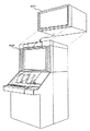
また、上記第一、第二及び第三の実施形態では、遊技機100及び遊技機400の筐体形状をアップライト型としたが、本発明はこれに限らず、図31に示すようなアップライト型筐体800にも適用可能である。このとき、図31に示すように、第二の遊技に関するシステム構成部分801は、スラント型筐体に物理的に追加するように配置するようになる。
【0320】
【発明の効果】
本発明によれば、他の場所に設置された遊技機に移動することなく第一の遊技を行っていた遊技機において第二の遊技へ参加可能となるので、遊技者による遊技の選択性が向上し、遊技場全体の稼働効率を高めることができる。
【図面の簡単な説明】
【図1】本発明の第一の実施形態のネットワーク構成図である。
【図2】本発明の第一の実施形態の遊技機100の概観図である。
【図3】本発明の第一の実施形態の遊技機100の停止図柄のデータテーブルを示す図である。
【図4】本発明の第一の実施形態の遊技機100の入賞停止態様と対応する配当コイン枚数を示す図である。
【図5】本発明の第一の実施形態の遊技機100のリールの回転及び停止の概要を示す図である。
【図6】本発明の第一の実施形態の遊技機100のハードブロック図である。
【図7】本発明の第一の実施形態の遊技機200の概観を示す図である。
【図8】本発明の第一の実施形態の遊技機200のハードブロック図である。
【図9】本発明の第一の実施形態の遊技機100における処理を示すフローチャートである。
【図10】本発明の第一の実施形態の遊技機100における処理を示すフローチャートである。
【図11】本発明の第一の実施形態の遊技機100及び遊技機200または300が通信して行う処理を示すフローチャートである。
【図12】本発明の第一の実施形態の遊技機100及び遊技機200または300が通信して行う処理を示すフローチャートである。
【図13】本発明の第一の実施形態の遊技機100及び遊技機200または300または500が通信して行う処理を示すフローチャートである。
【図14】本発明の第一の実施形態の遊技機100及び遊技機200が通信して行う処理を示すフローチャートである。
【図15】本発明の第一の実施形態の遊技機100の第二の表示装置に表示される第二の遊技の表示イメージ図である。
【図16】本発明の第二の実施形態のネットワーク構成図である。
【図17】本発明の第二の実施形態の遊技機300の概観図である。
【図18】本発明の第二の実施形態の遊技機300のハードブロック図である。
【図19】本発明の第二の実施形態の遊技機100及び遊技機300が通信して行う処理を示すフローチャートである。
【図20】本発明の第二の実施形態の遊技機100の第二の表示装置に表示される第二の遊技の表示イメージ図である。
【図21】本発明の第三の実施形態のネットワーク構成図である。
【図22】本発明の第三の実施形態の遊技機400の概観を示す図である。
【図23】本発明の第三の実施形態の遊技機400のハードブロック図である。
【図24】本発明の第三の実施形態の遊技機500の概観図である。
【図25】本発明の第三の実施形態の遊技機500のハードブロック図である。
【図26】本発明の第三の実施形態の遊技機400における処理を示すフローチャートである。
【図27】本発明の第三の実施形態の遊技機400における処理を示すフローチャートである。
【図28】本発明の第三の実施形態の遊技機400及び遊技機500が通信して行う処理を示すフローチャートである。
【図29】本発明の第三の実施形態の遊技機400の第二の表示装置に表示される第二の遊技の表示イメージ図である。
【図30】本発明の変形実施形態の遊技機100または400の第二の表示装置に表示される第二の遊技の表示イメージ図である。
【図31】本発明の変形実施形態のスラント型遊技機の概観図及びスラント型遊技機に第二の遊技に関するシステムを物理的に追加するイメージ図である。
【符号の説明】
100、200、300、400、500 遊技機
101、201、301、401、501 主制御回路
102、132、202、302、402、433、502 CPU
127、215、308、426、507 表示制御装置
128、216、309、508 表示装置
130、135、218、314、431、446、509 通信制御回路
131、432 制御回路
136、447、450 タッチセンサ
137、448 液晶駆動回路
138、449 液晶表示器
199、299、399、499 筐体
800 アップライト型筐体
801 第二の遊技に関するシステム構成部分
N ネットワーク
S1、S2、S3 遊技システム[0001]
TECHNICAL FIELD OF THE INVENTION
The present invention relates to a gaming system and a gaming machine.
[0002]
[Prior art]
In the amusement arcade, various gaming machines such as slot machines are installed, and so-called table games such as poker games, roulette, and kino are played. For this reason, for example, the player may feel monotonous to continuously play only the game of the slot machine, and may want to play another game.
[0003]
However, it is troublesome to leave the slot machine and participate in a game installed in another place having a different game content, and it is difficult for the player to continue the game with the same slot machine.
[0004]
Therefore, in order to solve this problem, in addition to the variable display section of the slot machine, another display section is provided for the second game, and a bingo game is performed by associating numbers with symbols stopped on the variable display section. A gaming machine has been proposed (for example, see Patent Document 1).
[0005]
[Patent Document 1]
JP-A-11-253610
[0006]
[Problems to be solved by the invention]
However, in such a game, it is not possible to satisfy the intention of the player to perform another game having different game contents, and as a result, the second game may be bored. There is.
[0007]
As an example, there is a case where the player wants to participate in a game that is different from the game content and is installed in another place, that is, a game that can be participated by a plurality of players, such as a horse racing game, a roulette, and a kino. However, when these games are played in a place different from the slot machine, there is a trouble that the player moves the gaming machines. Also, since the number of people who can participate in games such as horse racing games, roulette, keno, etc. is limited, even if a slot machine player interrupts the slot and tries to participate in games such as horse racing games, roulette, keno, etc. In some cases, it is not possible to participate, and it is not possible to easily participate in games with different game contents.
[0008]
The present invention has been made in view of the above problems, and a player playing a first game such as a slot machine can move to a second game having a different game content without moving the gaming machine. It is intended to provide a gaming system and a gaming machine that enable participation.
[0009]
[Means for Solving the Problems]
In order to achieve the above object, in the gaming system and the gaming machine of the present invention, the first gaming machine is provided with a second display unit different from the variable display unit for displaying the first game, It is connected to a second gaming machine in a communicable state and transmits and receives information related to a second game controlled by the second gaming machine, and transmits the second information to a player based on the information related to the second game. The display unit has a function of performing a second game.
[0010]
More specifically, the present invention provides the following.
[0011]
(1) A first gaming machine having an operation unit operable by a player to provide a first game, and a second game different from the first game and capable of participating by a plurality of players A second gaming machine that provides a game system, wherein the second gaming machine is communicably connected, wherein the second gaming machine stores a program for controlling the second game, Program execution means for executing the program, image data storage means for storing image data relating to the second game, and image data transmission for transmitting image data relating to the second game to the first gaming machine Means, the first game machine, the first game machine, the first game control means for controlling the first game, and a plurality of symbols required for the first game is variable First display means for displaying; Image data receiving means for receiving image data related to the second game transmitted from the second gaming machine, second display means for displaying an image based on the image data related to the second game, A game system comprising: game operation means for operating game control means for a game.
[0012]
(2) A first gaming machine having an operation unit operable by a player to provide a first game, and unlike the first game, a second gaming machine capable of participating by a plurality of players. A first game control means connected to a second gaming machine that provides the first game and capable of controlling the first game, and a plurality of symbols required for the first game being variably displayed. One display means, an image data receiving means for receiving image data related to the second game transmitted from the second gaming machine, and a second means for displaying an image based on the image data related to the second game A gaming machine comprising: display means; and game operation means for operating game contents of the second game.
[0013]
According to the inventions of (1) and (2), the first gaming machine is transmitted from the first display means for variably displaying a plurality of symbols necessary for the first game and the second gaming machine. Game data for receiving the image data related to the second game, and second display means for displaying an image based on the image data related to the second game. If the player feels monotonous in the first game, he may try to move to another gaming machine to perform the second game, If so, the intention to play the second game may be diminished, but the second machine in the gaming machine that played the first game without moving to the gaming machine installed in another place By making it possible to participate in the game, the player Pressure is promoted, will be to improve the game of selectivity by the player, it is possible to increase the operating efficiency of the entire game field.
[0014]
Further, it is possible to provide more players with an opportunity to participate in the second game.
[0015]
Furthermore, since the game device includes the "game operation means for operating the content of the second game", it is possible to operate the game controlled by the second game machine in the first game machine, and to the player, The content of the second game can be made operable at a location away from the second gaming machine.
[0016]
In addition, the second gaming machine may include “program storage means for storing a program for controlling the second game, program execution means for executing the program, and image data storage for storing image data related to the second game. Means, and image data transmitting means for transmitting image data relating to the second game to the first gaming machine '', thus eliminating the need to control the second game at the first gaming machine. The first game machine can execute the second game with a simple control structure.
[0017]
For example, in the case of a game that can be participated by a plurality of players, such as a horse racing game, a roulette wheel, a kino, and the like, if these gaming machines are arranged in locations different from the slot machine, the player of the slot machine interrupts the game. When a player wants to participate in a game such as a horse racing game, roulette, keno, or the like, the player must move the gaming machine. Also, since there is a limit to the number of people who can participate in games such as horse racing games, roulette, keno, etc., even if a slot machine player interrupts the slot and tries to participate in games such as horse racing games, roulette, keno, etc. You may not be able to participate in the game. However, by using the present invention, the trouble of having to move the gaming machine is relieved, and it becomes possible to easily participate in a game that can be participated by a plurality of players, and the player of the slot machine can play the game. When interrupting and wanting to participate in other games, it becomes possible to participate in other games without moving the gaming machine. Therefore, participation in games that can be participated by multiple players such as horse racing games, roulette, keno, etc. will be promoted, and players can participate in slots, or multiple players such as horse racing games, roulette, keno, etc. Since the selectivity of selecting one of the various games and playing the game is improved, the operating efficiency of the entire game hall can be increased.
[0018]
BEST MODE FOR CARRYING OUT THE INVENTION
Hereinafter, three preferred embodiments of the present invention will be described with reference to the drawings.
[0019]
In the following embodiments, description will be made using “coin” as a medium representing a game value. For example, “currency”, “token”, “game value information stored on a magnetic card or IC chip”, “game ball” , "Medals", and other media that can have a game value in place of "coins" may be used.
[0020]
[First embodiment]
In the first embodiment, a case will be described in which the first game of the present invention is a “slot” and the second game is a “horse racing game”.
[0021]
[Network configuration of gaming machines]
The gaming system S1 shown in FIG. 1 includes a network N, a plurality of
[0022]
The network N in the present embodiment is a network configured with a dedicated line based on a predetermined protocol of the gaming system S1.
[0023]
Note that the network N is not limited to a specific protocol and a dedicated line, but may be configured by the Internet constituted by a TCP / IP or UDP / IP protocol and a public line network.
[0024]
The
[0025]
[Overview of gaming machine 100]
FIG. 2 shows an overview of the
[0026]
On the front surface of the
[0027]
When a later-described 1-
[0028]
Inside the
[0029]
Further, below the
[0030]
The
[0031]
On the right side of the
[0032]
On the front surface of the
[0033]
The
[0034]
A C / P (Credit / Pay)
[0035]
When the state of the C / P switch is “On”, the state of the C / P switch is “Off” when the player presses the C /
[0036]
Conversely, when the state of the C / P switch is “Off”, when the C /
[0037]
A
[0038]
A
[0039]
On the front surface of the
[0040]
A
[0041]
A
[0042]
FIG. 3 is a table showing a layout example of symbols arranged on the reels 197 (197L, 197C, 197R). In the table shown in FIG. 3, the types of symbols are simplified and represented by reference numerals “A” to “H”. As shown in FIG. 3, symbols corresponding to the code numbers of the table are drawn on the outer peripheral surface of each of the
[0043]
As will be described later, this table is used for associating each rotation angle position of the
[0044]
FIG. 4 shows an example of a winning symbol combination table showing a relationship between a symbol combination winning as a winning and the number of coins to be paid out as a normal dividend when the symbol combination is achieved. In FIG. 4 as well, the types of symbols are simplified and represented by reference numerals “A” to “H”, similarly to FIG.
[0045]
For example, when all of the three
[0046]
FIG. 5 shows a mode in which the start switch 109 of the
[0047]
Referring to FIG. 5, (A), (B), and (C) show a mode in which three
[0048]
[Electrical Configuration of Gaming Machine 100]
FIG. 6 is a hardware block diagram of the
[0049]
Referring to FIG. 6, the control structure of
[0050]
The
[0051]
The first part surrounded by a broken line in FIG. 6 is the
[0052]
The
[0053]
Although the program according to the present embodiment is stored in the
[0054]
In the RAM 108, the above-described program body is stored at the time of execution, and the values of flags and variables used in the program are temporarily stored.
[0055]
Various peripheral devices are connected to the
[0056]
A random number sampling circuit 106 is connected to the
[0057]
A random number generator 105 is connected to the random number sampling circuit 106. A random number generated by the random number generator 105 at a constant period is sampled by the random number sampling circuit 106, and information on the random number is supplied to the
[0058]
Note that a frequency divider 104 is connected to the random number generator 105 so that a pulse with a constant cycle is supplied to the random number generator 105 so that the random number generator 105 generates a random number at a constant cycle. Is connected to a clock pulse generating circuit 103. With such a configuration, the clock pulse generation circuit 103 generates a random number using a pulse independent of the
[0059]
In the present embodiment, the
[0060]
The
[0061]
The drive control command issued from the
[0062]
By controlling the stepping
[0063]
Each of the
[0064]
The
[0065]
A
[0066]
Furthermore, a
[0067]
Note that BET means "betting a coin" in a game.
[0068]
Further, a C /
[0069]
Furthermore, a start switch 109 provided near the
[0070]
Further, a
[0071]
The
[0072]
The sound data is stored in the
[0073]
Furthermore, a
[0074]
A
[0075]
Further, a
[0076]
A second part surrounded by a broken line in FIG. 6 is a
[0077]
The control program for controlling the connected devices connected to the
[0078]
In the
[0079]
Various peripheral devices are connected to the
[0080]
The
[0081]
In the present embodiment, the
[0082]
Further, a liquid
[0083]
A
[0084]
In this embodiment, the liquid
[0085]
[Overview of gaming machine 200]
FIG. 7 shows an overview of the
[0086]
The
[0087]
A substantially
[0088]
The
[0089]
Two speakers 214 (214L, 214R) are provided on an upper portion of a housing 299 constituting a main body of the
[0090]
The display image displayed on the
[0091]
In the present embodiment, the
[0092]
[Electrical Configuration of Gaming Machine 200]
FIG. 8 is a hardware block diagram of the
[0093]
8 is a
[0094]
In the
[0095]
Although the program according to the present embodiment is recorded in the
[0096]
The
[0097]
Various peripheral devices are connected to the
[0098]
A random
[0099]
A
[0100]
Note that a
[0101]
In the present embodiment, the
[0102]
Further, a
[0103]
The
[0104]
The sound data is stored in the
[0105]
Further, a
[0106]
Further, a
[0107]
Further, the
[0108]
[Operation of gaming machine]
First, FIG. 9 shows a subroutine for controlling the BET processing executed in the main control circuit of the
[0109]
This subroutine is a process called by the player at the time of BET of the first game (slot) and the second game (horse racing game) in the
[0110]
As described above, BET processing is shared between the first game (slot) and the second game (horse racing game) because the
[0111]
Referring to FIG. 9, in step S11, it is determined whether or not a coin has been inserted. In this process, when the coin sensor 114 (see FIG. 6) of the
[0112]
Next, in step S12, an insertion coin number data addition process is performed. In this process, the
[0113]
Next, in step S13, it is determined with reference to the inserted coin number data stored in step S12 whether or not the upper limit of the BET number has been exceeded. In this process, the
[0114]
Next, in step S14, BET number data addition processing is performed. In this process, the
[0115]
On the other hand, in step S15, CREDIT number data addition processing is performed. In this process, for the inserted coin determined to exceed the upper limit of the number of bets in step S13, an addition process to the number of CREDIT is performed. The
[0116]
Next, in step S16, it is determined whether a BET operation has been performed. In this processing, if any one of the spin switch 110 (see FIG. 6), the 1-
[0117]
Next, in step S17, it is determined whether the number of CREDITs does not exist or the condition of exceeding the BET number upper limit is satisfied. In this process, the
[0118]
Next, in step S18, an addition process of the BET number data is performed. In this process, the
[0119]
Next, in step S19, a CREDIT number subtraction process is performed. In this process, the
[0120]
[Slot game processing]
Next, FIG. 10 shows a subroutine for controlling a slot game process executed in the main control circuit of the
[0121]
Referring to FIG. 10, in step S21, it is determined whether or not the bet amount data is “0”. In this process, the
[0122]
Next, in step S22, it is determined whether a game start operation has been performed. In this process, the
[0123]
Next, in a step S23, a random number lottery process is executed. In this process, the rotation speed and the stop symbol in the reel rotation stop process in step S24 described later are determined by the random numbers selected by lottery. In the present embodiment, the random number generator 105 of the
[0124]
Next, in step S24, a reel rotation stop process is executed. In this process, the
[0125]
The
[0126]
Next, in step S25, it is determined whether or not there is a winning. In this process, the
[0127]
Next, in step S26, a calculation process of payout number data is executed. In this process, the
[0128]
Next, in step S27, a payout process is executed. In this process, the
[0129]
Next, in step S28, a cumulative recording process of payout cumulative data is executed. In this process, the
[0130]
Next, in step S29, it is determined whether the C / P switch 113 (see FIG. 6) is pressed. In this process, when the C /
[0131]
[Transmission / reception processing of game data and image data related to second game]
Next, FIG. 11 shows a subroutine for performing communication between the
[0132]
FIG. 15 shows an example of game data and image data transmitted and received in this subroutine.
[0133]
Note that, as described later, this processing is executed at regular intervals by a timer controlled by the
[0134]
Further, it is a subroutine independent of the bet processing shown in FIG. 9 and the slot game processing shown in FIG.
[0135]
Referring to FIG. 11, in step S31,
[0136]
On the other hand, in step S32, the
[0137]
Next, in step S33, a process of displaying game-related data and image data is performed based on the reception signal received in step S32. In this process, the
[0138]
[Transfer processing of BET data related to the second game]
Next, FIG. 12 shows a subroutine for performing communication between the
[0139]
This subroutine is a subroutine showing a process bet by a player in a second game in the
[0140]
This subroutine is a subroutine independent of the slot game processing shown in FIG. 10 and the transmission / reception processing of game data and image data shown in FIG. 11, as long as a BET operation by a player is accepted in the
[0141]
Referring to FIG. 12, in step S41,
[0142]
The bet number input process by the player is a process performed on the assumption that a coin has been inserted into the
[0143]
Next, in step S42, a BET process is performed. In this process, the
[0144]
Next, in step S43, a process of transmitting the BET data input by the player in step S42 to the
[0145]
On the other hand, on the
[0146]
Next, in step S45,
[0147]
[Data transmission / reception processing related to the execution processing of the second game]
Next, FIG. 13 shows a subroutine for performing communication between the
[0148]
First, on the
[0149]
On the other hand, in step S52, a process of receiving the BET acceptance end notification information transmitted from the
[0150]
Next, in step S53, based on the signal reception of the BET reception end notification information in step S52, a process of stopping reception of any operation on the operation display unit of the
[0151]
Next, in step S54, a BET operation acceptance stop information display process is performed. In this process, based on the BET operation acceptance stop process executed in step S53, the fact that the process has been performed is displayed on the
[0152]
On the other hand, in the
[0153]
On the other hand, in the
[0154]
Next, in step S57, since it is determined in step S56 that there is a payout, a payout process for giving a payout to the player is performed. In this process, the
[0155]
On the other hand, in the
[0156]
On the other hand, in the
[0157]
Next, in step S60, a BET operation acceptance start process is performed. In this process, the
[0158]
Next, in step S61, a BET operation acceptance start display process is performed. In this process, the process is executed in accordance with the operation acceptance cancellation release process of the operation display unit of the
[0159]
[Second game execution process and data transmission / reception process]
Next, FIG. 14 shows a subroutine for performing communication between the
[0160]
Referring to FIG. 14, in
[0161]
Next, in step S72, a horse racing race start process is executed. The start process referred to here is that the result of the horse race is determined in step S71, and therefore, in step S72, the actual state of the horse race is transmitted to the
[0162]
Next, in step S73, a race status information transmission process is performed. This process is a process of continuously transmitting image data suitable for displaying a live race condition, which is synthesized and stored in step S72, to the
[0163]
On the other hand, in step S74 of the
[0164]
Next, in step S75, the
[0165]
On the other hand, in the
[0166]
Next, in step S77, a race end process is performed. In this processing, initialization of variables and storage areas arranged in the
[0167]
Next, in step S78, a payout number determination process is performed. In this process, the
[0168]
Next, in step S79, a process of transmitting the race result determined in step S71 and the payout result determined in step S78 to the
[0169]
On the other hand, in step S80 in the
[0170]
Next, in step S81, a process of displaying the information on the race result and the payout result received in step S80 on the
[0171]
[About Display Displayed on Second Display Device of Gaming Machine 100]
FIG. 15 is a display image of the second game (horse racing game) displayed on the second display device of the gaming machine, that is, the
[0172]
The
[0173]
The
[0174]
The
[0175]
The
[0176]
The
[0177]
The
[0178]
The
[0179]
The
[0180]
By configuring the gaming machine as described above and causing each gaming machine to perform processing, the slot player was slotted without moving to the horse racing game gaming machine installed elsewhere. It is possible to enable the gaming machine to participate in a horse racing game. Thereby, the participation of the slot player in the horse racing game is promoted, the selectivity of the game by the slot player is improved, and the operating efficiency of the entire game hall can be improved. Further, it is possible to provide more players with an opportunity to participate in the horse racing game.
[0181]
[Second embodiment]
Hereinafter, a second embodiment of the present invention will be described with reference to the drawings.
[0182]
In the second embodiment, a case is described in which the first game of the present invention is a “slot” and the second game is a “roulette” game.
[0183]
[Network Configuration Diagram of Second Embodiment]
The gaming system S2 shown in FIG. 16 includes a network N, a plurality of
[0184]
The
[0185]
[Overview of gaming machine 300]
FIG. 17 shows an overview of a
[0186]
The
[0187]
[Electrical Configuration of Gaming Machine 300]
FIG. 18 is a hardware block diagram of the
[0188]
The portion surrounded by the broken line in FIG. 18 is the
[0189]
Various control programs for controlling the
[0190]
The
[0191]
Various peripheral devices are connected to the
[0192]
A
[0193]
A
[0194]
A
[0195]
Further, a
[0196]
Furthermore, a
[0197]
Note that the configuration may not include the ball stop sensor. In this case, for example, the ball is rotated by spin of a roulette wheel, and the position where the ball has stopped is visually checked by a dealer, and the ball is stopped via an interface circuit group. A configuration may be adopted in which the stop number of the ball is input from an input device for inputting the stop number of the connected ball.
[0198]
[Operation of gaming machine]
The operation of the gaming machine of the second embodiment is the same as that of the first embodiment, but the subroutine called in the second game execution processing in FIG. 13 is different. The processing (roulette game) will be described.
[0199]
First, in step S91 of the
[0200]
Next, in step S92, a spin start process is performed. In this process, an operation signal of the
[0201]
Next, in step S93, a spin status image information transmission process is performed. In this process, the
[0202]
On the other hand, in the
[0203]
Next, in step S96, a spin status image information display process is performed. In this process, based on the spin status image information received in step S94, the
[0204]
On the other hand, in step S95, the
[0205]
Next, in step S97, ball stop position information and ball stop state image information transmission processing are performed. In this processing, a signal of the information of the ball stop position detected by the
[0206]
On the other hand, in the
[0207]
Next, in step S99, ball stop position information and ball stop state image information display processing are performed. In this process, the
[0208]
On the other hand, in step S100 of the
[0209]
On the other hand, in the
[0210]
[Regarding Display Displayed on Second Display Device of
FIG. 20 is a display image of the second game (roulette game) in the second embodiment, which is displayed on the second display device of the gaming machine, that is, the
[0211]
The
[0212]
The
[0213]
The
[0214]
When the player bets a coin, the
[0215]
The
[0216]
The
[0219]
By configuring a gaming machine as described above and causing each gaming machine to perform processing, a slot player was able to perform a slot without moving to a roulette game gaming table installed in another place. It is possible to enable a gaming machine to participate in a roulette game. As a result, the participation of the slot player in the roulette game is promoted, the selectivity of the game by the slot player is improved, and the operating efficiency of the entire game hall can be increased. Further, it is possible to provide more players with an opportunity to participate in the roulette game.
[0218]
[Third embodiment]
Hereinafter, a third embodiment of the present invention will be described with reference to the drawings.
[0219]
In the third embodiment, a case where the first game of the present invention is “Video Poker” and the second game is “Kino” game is shown.
[0220]
[Network Configuration Diagram of Third Embodiment]
The gaming system S3 shown in FIG. 21 includes a network N, a plurality of
[0221]
The
[0222]
[Overview of gaming machine 400]
FIG. 22 shows an overview of a
[0223]
A
[0224]
On the
[0225]
On the screen of the
[0226]
The five “HOLD”
[0227]
When the five “HOLD”
[0228]
In the present invention, the five “HOLD”
[0229]
Above the
[0230]
The CREDIT
[0231]
Further, above the CREDIT
[0232]
In the third embodiment, it is assumed that the
[0233]
A
[0234]
On the front surface of the
[0235]
Speakers 425 (425R and 425L) are provided below the front surface of the
[0236]
A
[0237]
[Electrical Configuration of Gaming Machine 400]
FIG. 23 is a hardware block diagram of the
[0238]
Referring to FIG. 23, the control structure of
[0239]
In the
[0240]
The first portion surrounded by a broken line in FIG. 23 is the
[0241]
The
[0242]
Although the program according to the present embodiment is recorded in the
[0243]
In the
[0244]
Various peripheral devices are connected to the
[0245]
The
[0246]
A random number generator 405 is connected to the random
[0247]
Note that a frequency divider 404 is connected to the random number generator 405 in order to supply a pulse with a constant cycle to the random number generator 405 so that the random number generator 405 generates a random number at a constant cycle. Is connected to a clock
[0248]
In the present embodiment, the
[0249]
A
[0250]
Furthermore, a
[0251]
Note that BET means "betting a coin" in a game.
[0252]
Further, a
[0253]
In the poker game, DEAL is a process of distributing playing cards at the beginning, and DRAW is a process of exchanging playing cards that are not held among the DEAL playing cards.
[0254]
Furthermore, a C /
[0255]
Further, a sound CPU 421 is connected to the
[0256]
The
[0257]
The sound data is stored in the
[0258]
Furthermore, a
[0259]
A hopper drive circuit 417 is connected to the
[0260]
Further, a
[0261]
A second portion surrounded by a broken line in FIG. 23 is a
[0262]
In the
[0263]
The
[0264]
Various peripheral devices are connected to the
[0265]
The
[0266]
In the present embodiment, the
[0267]
Further, a liquid
[0268]
A
[0269]
In the present embodiment, the liquid
[0270]
[Overview of gaming machine 500]
FIG. 24 shows an overview of a
[0271]
The
[0272]
Note that the
[0273]
The
[0274]
Further, the
[0275]
[Electrical Configuration of Gaming Machine 500]
FIG. 25 is a hardware block diagram of the
[0276]
The portion surrounded by the broken line in FIG. 25 is the
[0277]
Various control programs for controlling the
[0278]
The
[0279]
Various peripheral devices are connected to the
[0280]
A
[0281]
A
[0282]
[Operation of gaming machine 400]
FIGS. 26 and 27 show the draw poker process for controlling the
[0283]
Before the following processing is performed in the
[0284]
As shown in FIG. 26, in step S111, a BET process is performed. In this process, a subroutine similar to the BET process shown in FIG. 9 is called. By this processing, the number of coins bet on the
[0285]
In step S112, a process of determining the number of BETs is performed. By this processing, it is determined whether or not the number of coins bet by the operation of the player is one or more. If the
[0286]
Next, step S113 is detection processing of a pressing operation of the DEAL switch by the player. By this processing, the
[0287]
Next, in step S114, a DEAL process is performed. By this processing, the
[0288]
Next, in step S115, a first winning combination determination process is performed. By this processing, the
[0289]
Next, in step S116, a HOLD switch pressing operation is performed. When the player selects a card to be held among the five cards distributed in step S114 and touches the “HOLD”
[0290]
Next, in step S117, a card HOLD process is performed. In this process, the HOLD process of the card is performed based on the signal detection of the
[0291]
Next, in step S118, DRAW processing is performed. By this processing, the
[0292]
As shown in FIG. 27, in step S119, a second winning combination determination process is performed. By this processing, the
[0293]
Next, in step S120, a process of determining the result of the combination determination process in step S115 or step S119 is performed. By this process, the
[0294]
Next, step S121 is a process of determining whether or not the player plays the “DOUBLE UP game”. The “DOUBLE UP game” is a game in which after a certain role is established and a corresponding payout is awarded to a player, the player wins the obtained payout. The playing card is drawn one by one by the dealer and the player controlled by the
[0295]
Next, in a step S122, a DOUBLE UP game process is performed. After the end of this process, the process moves to step S123.
[0296]
Next, in step S123, a process of determining a DOUBLE UP game result in step S122 is performed. In this process, the
[0297]
Next, in step S124, since the player has won in the DOUBLE UP game in step S123, the
[0298]
In step S125, since the player lost in the DOUBLE UP game in step S123, the
[0299]
On the other hand, in step S126, a payout payout process is performed. The
[0300]
Next, in step S127, various variable initialization processing is performed. The
[0301]
[Operation of gaming machine 500]
The operation of the
[0302]
First, in the
[0303]
Next, in step S132, a keno lottery is performed by the dealer. After the end of this process, the process moves to step S133.
[0304]
Next, in step S133, a process of inputting the number of the lottery ball is performed. The
[0305]
Next, in step S134, a process of converting the information of the ball number input in step S133 and lit on the winning
[0306]
On the other hand, in step S135 of the
[0307]
Next, in step S137, a process of displaying the number of the lottery ball is performed. In this process, based on the detection signal of the signal of the information of the ball number supplied to the
[0308]
On the other hand, in step S136 of the
[0309]
[Regarding Display Displayed on Second Display Device of
FIG. 29 is a display image of the second game (Kino game) in the third embodiment, which is displayed on the second display device of the gaming machine, that is, the
[0310]
The
[0311]
The
[0312]
The
[0313]
The
[0314]
The
[0315]
The
[0316]
By configuring a gaming machine as described above and causing each gaming machine to perform processing, a game in which a player of Video Poker performs a slot without moving to a kino game gaming table installed in another place It is possible to make it possible to participate in the kino game on the machine. As a result, the participation of the video poker player in the kino game is promoted, the selectivity of the game by the video poker player is improved, and the operating efficiency of the entire game hall can be increased. Further, it is possible to provide more players with an opportunity to participate in the kino game.
[0317]
[Other Modifications]
In the first, second, and third embodiments, the first game is a slot, the second game is a horse racing game or roulette, or the first game is poker, and the second game is a keno. However, the present invention is not limited to these combinations, and can be implemented by freely combining the first game and the second game. For example, the game is not limited to slots, video poker, horse racing games, roulette, and kino, but may be mahjong, blackjack, flower cards, bingo, baccarat, and the like. . At this time, it does not matter which game corresponds to the first game and the second game.
[0318]
In the first, second, and third embodiments, the number of the second game incorporated in one gaming machine is one. However, the present invention is not limited to this, and may include a plurality of second games. It may be selectable. For example, on the
[0319]
In the first, second, and third embodiments, the
[0320]
【The invention's effect】
According to the present invention, since it is possible to participate in the second game in the gaming machine that was playing the first game without moving to the gaming machine installed in another place, the selectivity of the game by the player is improved. It is possible to improve the operation efficiency of the entire game arcade.
[Brief description of the drawings]
FIG. 1 is a network configuration diagram of a first embodiment of the present invention.
FIG. 2 is a schematic view of the
FIG. 3 is a view showing a data table of a stop symbol of the
FIG. 4 is a diagram illustrating a payout coin number corresponding to a winning stop mode of the
FIG. 5 is a diagram showing an outline of rotation and stop of a reel of the
FIG. 6 is a hardware block diagram of the
FIG. 7 is a view showing an overview of the
FIG. 8 is a hardware block diagram of the
FIG. 9 is a flowchart illustrating a process in the
FIG. 10 is a flowchart illustrating a process in the
FIG. 11 is a flowchart illustrating a process performed by the
FIG. 12 is a flowchart illustrating a process performed by the
FIG. 13 is a flowchart illustrating a process performed by the
FIG. 14 is a flowchart illustrating a process performed by the
FIG. 15 is a display image diagram of a second game displayed on the second display device of the
FIG. 16 is a network configuration diagram according to a second embodiment of the present invention.
FIG. 17 is a schematic view of a
FIG. 18 is a hardware block diagram of the
FIG. 19 is a flowchart illustrating a process performed by the
FIG. 20 is a display image diagram of a second game displayed on a second display device of the
FIG. 21 is a network configuration diagram according to a third embodiment of the present invention.
FIG. 22 is a view illustrating an overview of a
FIG. 23 is a hardware block diagram of a
FIG. 24 is a schematic view of a
FIG. 25 is a hardware block diagram of a
FIG. 26 is a flowchart illustrating processing in the
FIG. 27 is a flowchart showing processing in the
FIG. 28 is a flowchart showing processing performed by the
FIG. 29 is a display image diagram of a second game displayed on a second display device of the
FIG. 30 is a display image diagram of a second game displayed on the second display device of the
FIG. 31 is an outline view of a slanted gaming machine according to a modified embodiment of the present invention and an image diagram of physically adding a system relating to a second game to the slanted gaming machine.
[Explanation of symbols]
100, 200, 300, 400, 500 gaming machines
101, 201, 301, 401, 501 Main control circuit
102, 132, 202, 302, 402, 433, 502 CPU
127, 215, 308, 426, 507 Display control device
128, 216, 309, 508 Display device
130, 135, 218, 314, 431, 446, 509 Communication control circuit
131, 432 control circuit
136, 447, 450 Touch sensor
137, 448 LCD drive circuit
138, 449 Liquid crystal display
199,299,399,499 Housing
800 Upright type housing
801 System components related to the second game
N network
S1, S2, S3 game system
Claims (2)
前記第二の遊技機は、
前記第二の遊技を制御するプログラムを格納するプログラム格納手段と、前記プログラムを実行するプログラム実行手段と、前記第二の遊技に関する画像データを記憶する画像データ記憶手段と、前記第二の遊技に関する画像データを前記第一の遊技機に対して送信する画像データ送信手段と、を含む第二の遊技制御手段を備え、
前記第一の遊技機は、
第一の遊技を制御する第一の遊技制御手段と、前記第一の遊技に必要な複数の図柄を可変表示する第一の表示手段と、前記第二の遊技機から送信された前記第二の遊技に関する画像データを受信する画像データ受信手段と、前記第二の遊技に関する画像データに基づく画像を表示する第二の表示手段と、前記第二の遊技の遊技制御手段を操作する遊技操作手段と、を備えたことを特徴とする遊技システム。A first gaming machine having an operation unit operable by a player to provide a first game and a second game different from the first game and capable of participating by a plurality of players. A second gaming machine, and a gaming system connected in a communicable state,
The second gaming machine,
Program storage means for storing a program for controlling the second game, program execution means for executing the program, image data storage means for storing image data relating to the second game, and Image data transmitting means for transmitting image data to the first gaming machine, and a second game control means,
The first gaming machine,
First game control means for controlling the first game, first display means for variably displaying a plurality of symbols necessary for the first game, and the second game machine transmitted from the second game machine Image data receiving means for receiving image data related to the second game, second display means for displaying an image based on the image data related to the second game, and game operation means for operating the game control means for the second game And a game system comprising:
前記第一の遊技とは異なり、複数の遊技者により参加可能な第二の遊技を提供する第二の遊技機と通信可能な状態に接続され、
第一の遊技を制御する第一の遊技制御手段と、前記第一の遊技に必要な複数の図柄を可変表示する第一の表示手段と、前記第二の遊技機から送信された前記第二の遊技に関する画像データを受信する画像データ受信手段と、前記第二の遊技に関する画像データに基づく画像を表示する第二の表示手段と、前記第二の遊技の遊技内容を操作するための遊技操作手段と、を備えたことを特徴とする遊技機。A first gaming machine having an operation unit operable by a player to provide a first game,
Unlike the first game, connected to a second gaming machine that provides a second game that can be participated by a plurality of players, in a communicable state,
First game control means for controlling the first game, first display means for variably displaying a plurality of symbols necessary for the first game, and the second game machine transmitted from the second game machine Image data receiving means for receiving image data related to the second game, second display means for displaying an image based on the image data related to the second game, and a game operation for operating the game content of the second game And a game machine.
Priority Applications (7)
| Application Number | Priority Date | Filing Date | Title |
|---|---|---|---|
| JP2003103483A JP2004305440A (en) | 2003-04-07 | 2003-04-07 | Game system and game machine |
| US10/812,973 US20050101385A1 (en) | 2003-04-07 | 2004-03-31 | Gaming system and gaming machine therefor |
| EP04007959A EP1467329A3 (en) | 2003-04-07 | 2004-04-01 | Gaming system and gaming machine therefor |
| ZA200402598A ZA200402598B (en) | 2003-04-07 | 2004-04-01 | Gaming system and gaming machine therefor. |
| AU2004201397A AU2004201397A1 (en) | 2003-04-07 | 2004-04-05 | Gaming system and gaming machine therefor |
| CNA200410031024XA CN1535746A (en) | 2003-04-07 | 2004-04-07 | Game system and game computer |
| US12/183,846 US20080300057A1 (en) | 2003-04-07 | 2008-07-31 | Gaming system and gaming machine therefor |
Applications Claiming Priority (1)
| Application Number | Priority Date | Filing Date | Title |
|---|---|---|---|
| JP2003103483A JP2004305440A (en) | 2003-04-07 | 2003-04-07 | Game system and game machine |
Publications (1)
| Publication Number | Publication Date |
|---|---|
| JP2004305440A true JP2004305440A (en) | 2004-11-04 |
Family
ID=32866713
Family Applications (1)
| Application Number | Title | Priority Date | Filing Date |
|---|---|---|---|
| JP2003103483A Pending JP2004305440A (en) | 2003-04-07 | 2003-04-07 | Game system and game machine |
Country Status (6)
| Country | Link |
|---|---|
| US (2) | US20050101385A1 (en) |
| EP (1) | EP1467329A3 (en) |
| JP (1) | JP2004305440A (en) |
| CN (1) | CN1535746A (en) |
| AU (1) | AU2004201397A1 (en) |
| ZA (1) | ZA200402598B (en) |
Cited By (2)
| Publication number | Priority date | Publication date | Assignee | Title |
|---|---|---|---|---|
| JP2006231038A (en) * | 2005-01-28 | 2006-09-07 | Aruze Corp | Gaming machine and gaming system |
| JP2010252870A (en) * | 2009-04-21 | 2010-11-11 | Taito Corp | Token game machine and mass token game machine |
Families Citing this family (58)
| Publication number | Priority date | Publication date | Assignee | Title |
|---|---|---|---|---|
| US7273415B2 (en) | 2000-09-07 | 2007-09-25 | Igt | Gaming device having a bonus scheme with multiple selection groups |
| US7666093B2 (en) | 2004-08-03 | 2010-02-23 | Igt | Gaming method and device involving progressive wagers |
| US7963847B2 (en) | 2004-08-19 | 2011-06-21 | Igt | Gaming system having multiple gaming machines which provide bonus awards |
| US8021230B2 (en) | 2004-08-19 | 2011-09-20 | Igt | Gaming system having multiple gaming machines which provide bonus awards |
| US7892093B2 (en) | 2004-08-19 | 2011-02-22 | Igt | Gaming system having multiple gaming machines which provide bonus awards |
| WO2006023401A1 (en) | 2004-08-19 | 2006-03-02 | Igt | Gaming system having multiple gaming machines which provide bonus awards |
| US8251791B2 (en) | 2004-08-19 | 2012-08-28 | Igt | Gaming system having multiple gaming machines which provide bonus awards |
| US8668564B2 (en) | 2005-01-24 | 2014-03-11 | Solution Champion Limited | Jackpot method and system |
| US7922587B2 (en) | 2005-01-24 | 2011-04-12 | Jay Chun | Betting terminal and system |
| US8920238B2 (en) | 2005-01-24 | 2014-12-30 | Jay Chun | Gaming center allowing switching between games based upon historical results |
| US8210920B2 (en) | 2005-01-24 | 2012-07-03 | Jay Chun | Methods and systems for playing baccarat jackpot |
| US8308559B2 (en) | 2007-05-07 | 2012-11-13 | Jay Chun | Paradise box gaming system |
| US9940778B2 (en) | 2005-01-24 | 2018-04-10 | Igt | System for monitoring and playing a plurality of live casino table games |
| US7914368B2 (en) | 2005-08-05 | 2011-03-29 | Jay Chun | Methods and systems for playing baccarat jackpot with an option for insurance betting |
| US9704348B2 (en) | 2005-01-24 | 2017-07-11 | Igt | Jackpot method and system |
| US9640017B2 (en) | 2005-08-31 | 2017-05-02 | Igt | Gaming system and method employing rankings of outcomes from multiple gaming machines to determine awards |
| US7819745B2 (en) | 2005-09-06 | 2010-10-26 | Igt | Gaming system which provides multiple players multiple bonus awards |
| US7828649B2 (en) | 2005-09-06 | 2010-11-09 | Igt | Gaming system and method for providing group play with divided bonus features |
| US7597621B2 (en) | 2005-09-06 | 2009-10-06 | Igt | Gaming device having progressive awards and supplemental awards |
| US7753782B2 (en) | 2005-09-06 | 2010-07-13 | Igt | Gaming system and method for providing multiple players multiple bonus awards |
| US7500913B2 (en) | 2005-09-06 | 2009-03-10 | Igt | Gaming system which provides multiple players multiple bonus awards |
| US8137188B2 (en) | 2005-09-09 | 2012-03-20 | Igt | Server based gaming system having multiple progressive awards |
| US7841939B2 (en) | 2005-09-09 | 2010-11-30 | Igt | Server based gaming system having multiple progressive awards |
| US8128491B2 (en) | 2005-09-09 | 2012-03-06 | Igt | Server based gaming system having multiple progressive awards |
| US7780520B2 (en) | 2006-03-15 | 2010-08-24 | Igt | Gaming device having multiple different types of progressive awards |
| US7677971B2 (en) | 2006-06-09 | 2010-03-16 | Igt | Gaming system and method for enabling a player to select progressive awards to try for and chances of winning progressive awards |
| US7674178B2 (en) | 2006-06-09 | 2010-03-09 | Igt | Gaming system and method for enabling a player to select progressive awards to try for and chances of winning progressive awards |
| AU2007257940B2 (en) | 2006-06-09 | 2013-02-07 | Igt | Gaming System and Method for Enabling a Player to Select Progressive Awards to Try for and Chances of Winning Progressive Awards |
| US8070597B2 (en) | 2006-08-03 | 2011-12-06 | Igt | Gaming device and method having multiple progressive award levels and a secondary game for advancing through the progressive award levels |
| US8012014B2 (en) | 2006-08-22 | 2011-09-06 | Igt | Gaming system having awards provided based on rate of play |
| US7744459B2 (en) | 2006-08-24 | 2010-06-29 | Aruze Gaming America, Inc. | Game system including slot machines and game control method thereof |
| US8523665B2 (en) | 2006-10-11 | 2013-09-03 | Igt | Gaming system and method having multi-level mystery triggered progressive awards |
| US7914377B2 (en) | 2006-11-07 | 2011-03-29 | Igt | Gaming device with dynamic progressive and bonus architecture |
| US7963845B2 (en) | 2006-11-08 | 2011-06-21 | Igt | Gaming system and method with multiple progressive award levels and a skill based determination of providing one of the progressive award levels |
| US20080108430A1 (en) | 2006-11-08 | 2008-05-08 | Igt | Gaming system and method which provides players an opportunity to win a progressive award |
| US9047733B2 (en) | 2006-11-08 | 2015-06-02 | Igt | Gaming system and method for providing multiple level progressive awards with increased odds of winning higher level progressive awards |
| US8105149B2 (en) | 2006-11-10 | 2012-01-31 | Igt | Gaming system and method providing venue wide simultaneous player participation based bonus game |
| AU2015204295B2 (en) * | 2006-11-28 | 2016-06-09 | Aristocrat Technologies Australia Pty Limited | Gaming apparatus and method involving secondary display |
| AU2010203055B2 (en) * | 2006-11-28 | 2013-05-09 | Aristocrat Technologies Australia Pty Ltd | Gaming apparatus and method involving secondary display |
| AU2007234537B8 (en) * | 2006-11-28 | 2010-09-16 | Aristocrat Technologies Australia Pty Ltd | Gaming apparatus and method involving secondary display |
| JP2008178469A (en) * | 2007-01-23 | 2008-08-07 | Aruze Corp | Game apparatus and method of playing games |
| AU2008202090A1 (en) * | 2007-06-07 | 2009-01-08 | Aristocrat Technologies Australia Pty Limited | Method of credit input and a gaming system |
| US20090020951A1 (en) * | 2007-07-19 | 2009-01-22 | John Colacone | One bet poker |
| JP2009213831A (en) * | 2008-03-06 | 2009-09-24 | Aruze Gaming America Inc | Gaming system for betting on any team formed with a predetermined number of characters, gaming machine, and gaming system control method |
| JP2009213829A (en) * | 2008-03-06 | 2009-09-24 | Aruze Gaming America Inc | Gaming system and gaming system control method for betting on payout amount of player who has won award aside from bet to a plurality of characters |
| JP2009213830A (en) * | 2008-03-06 | 2009-09-24 | Aruze Gaming America Inc | Gaming system for betting on any team formed with a predetermined number of characters appearing in racing game of playing a predetermined number of races as one set, gaming machine, and gaming system control method |
| JP2009213827A (en) * | 2008-03-06 | 2009-09-24 | Aruze Gaming America Inc | Gaming system for betting on any team formed with a predetermined number of characters, gaming machine and gaming system control method |
| US8376836B2 (en) | 2008-11-07 | 2013-02-19 | Igt | Server based gaming system and method for providing deferral of bonus events |
| US10002492B2 (en) | 2012-09-18 | 2018-06-19 | Tipping Point Group, Llc | Method of modifying a primary game of an existing legacy gaming machine to include secondary game features |
| US10607441B2 (en) | 2012-09-18 | 2020-03-31 | Tipping Point Group, Llc | Method of modifying a primary game of an existing legacy gaming machine to include secondary game features |
| US8900057B2 (en) | 2012-09-18 | 2014-12-02 | Tipping Point Group, Llc | Seamless initiation of primary and secondary games at modified gaming machines |
| US10614667B2 (en) | 2012-09-18 | 2020-04-07 | Tipping Point Group, Llc | Method of modifying a primary game of an existing legacy gaming machine to include secondary awards |
| US9224268B2 (en) * | 2012-12-10 | 2015-12-29 | Bally Gaming, Inc. | Gaming system with privacy features |
| JP2014209974A (en) | 2013-04-17 | 2014-11-13 | 株式会社ユニバーサルエンターテインメント | Gaming machine |
| US20170301179A1 (en) * | 2016-04-18 | 2017-10-19 | Extreme Live Gaming Ltd | Live online gaming |
| TWI619533B (en) * | 2016-12-27 | 2018-04-01 | Huang yi han | Game method and game device using physical physical probability unit |
| US11605268B2 (en) | 2019-11-22 | 2023-03-14 | Castle Hill Holding Llc | System and method for wagering on past events |
| US11948434B2 (en) | 2021-02-02 | 2024-04-02 | Castle Hill Holding Llc | Method and system for conducting wagers |
Family Cites Families (18)
| Publication number | Priority date | Publication date | Assignee | Title |
|---|---|---|---|---|
| US5393057A (en) * | 1992-02-07 | 1995-02-28 | Marnell, Ii; Anthony A. | Electronic gaming apparatus and method |
| US5242163A (en) * | 1992-08-27 | 1993-09-07 | D.D. Stud Inc. | Casino game system |
| US5762552A (en) * | 1995-12-05 | 1998-06-09 | Vt Tech Corp. | Interactive real-time network gaming system |
| US6050895A (en) * | 1997-03-24 | 2000-04-18 | International Game Technology | Hybrid gaming apparatus and method |
| US6135884A (en) * | 1997-08-08 | 2000-10-24 | International Game Technology | Gaming machine having secondary display for providing video content |
| WO1999045509A1 (en) * | 1998-03-06 | 1999-09-10 | Mikohn Gaming Corporation | Gaming machines with bonusing |
| US6416408B2 (en) * | 1998-06-29 | 2002-07-09 | Anchor Gaming | Method of playing a group participation game |
| US7008324B1 (en) * | 1998-10-01 | 2006-03-07 | Paltronics, Inc. | Gaming device video display system |
| US6386974B1 (en) * | 1998-10-09 | 2002-05-14 | Anchor Gaming | Method of playing game and gaming device with interactive driving game display |
| US6579184B1 (en) * | 1999-12-10 | 2003-06-17 | Nokia Corporation | Multi-player game system |
| CA2403361A1 (en) * | 2000-04-05 | 2001-10-18 | Ods Properties, Inc. | Interactive wagering systems and methods with multiple television feeds |
| US7470196B1 (en) * | 2000-10-16 | 2008-12-30 | Wms Gaming, Inc. | Method of transferring gaming data on a global computer network |
| US20040137978A1 (en) * | 2000-12-28 | 2004-07-15 | Cole Joseph W. | Ergonomically-designed dual station, dual display gaming station with player conveniences |
| US6786824B2 (en) * | 2001-05-25 | 2004-09-07 | Igt | Method, apparatus, and system for providing a player with opportunities to win a feature event award |
| US6652378B2 (en) * | 2001-06-01 | 2003-11-25 | Igt | Gaming machines and systems offering simultaneous play of multiple games and methods of gaming |
| US6984174B2 (en) * | 2001-12-20 | 2006-01-10 | Igt | Method and apparatus for a player-controllable bonus game |
| US8157633B2 (en) * | 2002-08-30 | 2012-04-17 | Igt | Gaming device having a multi-trigger bonus |
| AU2003270756A1 (en) * | 2002-09-16 | 2004-04-30 | Paltronics, Inc. | Multi-game system |
-
2003
- 2003-04-07 JP JP2003103483A patent/JP2004305440A/en active Pending
-
2004
- 2004-03-31 US US10/812,973 patent/US20050101385A1/en not_active Abandoned
- 2004-04-01 EP EP04007959A patent/EP1467329A3/en not_active Withdrawn
- 2004-04-01 ZA ZA200402598A patent/ZA200402598B/en unknown
- 2004-04-05 AU AU2004201397A patent/AU2004201397A1/en not_active Abandoned
- 2004-04-07 CN CNA200410031024XA patent/CN1535746A/en active Pending
-
2008
- 2008-07-31 US US12/183,846 patent/US20080300057A1/en not_active Abandoned
Cited By (3)
| Publication number | Priority date | Publication date | Assignee | Title |
|---|---|---|---|---|
| JP2006231038A (en) * | 2005-01-28 | 2006-09-07 | Aruze Corp | Gaming machine and gaming system |
| JP4615448B2 (en) * | 2005-01-28 | 2011-01-19 | 株式会社ユニバーサルエンターテインメント | Game machine and game system |
| JP2010252870A (en) * | 2009-04-21 | 2010-11-11 | Taito Corp | Token game machine and mass token game machine |
Also Published As
| Publication number | Publication date |
|---|---|
| ZA200402598B (en) | 2004-10-15 |
| EP1467329A3 (en) | 2005-12-07 |
| US20050101385A1 (en) | 2005-05-12 |
| US20080300057A1 (en) | 2008-12-04 |
| AU2004201397A1 (en) | 2004-10-21 |
| EP1467329A2 (en) | 2004-10-13 |
| CN1535746A (en) | 2004-10-13 |
Similar Documents
| Publication | Publication Date | Title |
|---|---|---|
| JP2004305440A (en) | Game system and game machine | |
| US8128484B2 (en) | Game system generating second game according to game result of a device and allowing other devices to participate in second game thus generated | |
| JP4756633B2 (en) | game machine | |
| US7789752B2 (en) | Gaming system including slot machines and gaming control method thereof | |
| JP2002360776A (en) | Game machine | |
| JP2004033615A (en) | Game machine, server, and program | |
| JP2007075528A (en) | Game machine | |
| JP4290443B2 (en) | Game machine | |
| JP2004337508A (en) | Game machine | |
| JP2004337506A (en) | Game machine | |
| US7798897B2 (en) | Gaming system including slot machines and gaming control method thereof | |
| EA010453B1 (en) | Gaming machine | |
| JP2007029642A (en) | Game machine | |
| JP2008062048A (en) | Gaming system including slot machines and gaming control method thereof | |
| US7892086B2 (en) | Gaming system including slot machines and gaming control method thereof | |
| JP4678845B2 (en) | game machine | |
| JP2009100841A (en) | Game system in which a plurality of slot machines scramble for awards | |
| JP2008049119A (en) | Game system and game control method, which include slot machine | |
| JP2006230936A (en) | Game machine | |
| JP2006325651A (en) | Game machine | |
| JP2009125481A (en) | Game machine | |
| JP2009142629A (en) | Gaming machine | |
| JP2006320536A (en) | Game machine | |
| JP2003180941A (en) | Slot machine | |
| JP2006020779A (en) | Game machine |
Legal Events
| Date | Code | Title | Description |
|---|---|---|---|
| A621 | Written request for application examination |
Free format text: JAPANESE INTERMEDIATE CODE: A621 Effective date: 20051110 |
|
| A977 | Report on retrieval |
Free format text: JAPANESE INTERMEDIATE CODE: A971007 Effective date: 20080528 |
|
| A131 | Notification of reasons for refusal |
Free format text: JAPANESE INTERMEDIATE CODE: A131 Effective date: 20080603 |
|
| A521 | Written amendment |
Free format text: JAPANESE INTERMEDIATE CODE: A523 Effective date: 20080731 |
|
| A02 | Decision of refusal |
Free format text: JAPANESE INTERMEDIATE CODE: A02 Effective date: 20090120 |