JP2004239320A - Reduction gear - Google Patents
Reduction gear Download PDFInfo
- Publication number
- JP2004239320A JP2004239320A JP2003027425A JP2003027425A JP2004239320A JP 2004239320 A JP2004239320 A JP 2004239320A JP 2003027425 A JP2003027425 A JP 2003027425A JP 2003027425 A JP2003027425 A JP 2003027425A JP 2004239320 A JP2004239320 A JP 2004239320A
- Authority
- JP
- Japan
- Prior art keywords
- ring
- bearing
- housing
- output shaft
- gear
- Prior art date
- Legal status (The legal status is an assumption and is not a legal conclusion. Google has not performed a legal analysis and makes no representation as to the accuracy of the status listed.)
- Pending
Links
Images


Classifications
-
- F—MECHANICAL ENGINEERING; LIGHTING; HEATING; WEAPONS; BLASTING
- F16—ENGINEERING ELEMENTS AND UNITS; GENERAL MEASURES FOR PRODUCING AND MAINTAINING EFFECTIVE FUNCTIONING OF MACHINES OR INSTALLATIONS; THERMAL INSULATION IN GENERAL
- F16C—SHAFTS; FLEXIBLE SHAFTS; ELEMENTS OR CRANKSHAFT MECHANISMS; ROTARY BODIES OTHER THAN GEARING ELEMENTS; BEARINGS
- F16C35/00—Rigid support of bearing units; Housings, e.g. caps, covers
- F16C35/04—Rigid support of bearing units; Housings, e.g. caps, covers in the case of ball or roller bearings
- F16C35/06—Mounting or dismounting of ball or roller bearings; Fixing them onto shaft or in housing
- F16C35/063—Fixing them on the shaft
-
- F—MECHANICAL ENGINEERING; LIGHTING; HEATING; WEAPONS; BLASTING
- F16—ENGINEERING ELEMENTS AND UNITS; GENERAL MEASURES FOR PRODUCING AND MAINTAINING EFFECTIVE FUNCTIONING OF MACHINES OR INSTALLATIONS; THERMAL INSULATION IN GENERAL
- F16C—SHAFTS; FLEXIBLE SHAFTS; ELEMENTS OR CRANKSHAFT MECHANISMS; ROTARY BODIES OTHER THAN GEARING ELEMENTS; BEARINGS
- F16C19/00—Bearings with rolling contact, for exclusively rotary movement
- F16C19/22—Bearings with rolling contact, for exclusively rotary movement with bearing rollers essentially of the same size in one or more circular rows, e.g. needle bearings
- F16C19/34—Bearings with rolling contact, for exclusively rotary movement with bearing rollers essentially of the same size in one or more circular rows, e.g. needle bearings for both radial and axial load
- F16C19/36—Bearings with rolling contact, for exclusively rotary movement with bearing rollers essentially of the same size in one or more circular rows, e.g. needle bearings for both radial and axial load with a single row of rollers
- F16C19/364—Bearings with rolling contact, for exclusively rotary movement with bearing rollers essentially of the same size in one or more circular rows, e.g. needle bearings for both radial and axial load with a single row of rollers with tapered rollers, i.e. rollers having essentially the shape of a truncated cone
-
- F—MECHANICAL ENGINEERING; LIGHTING; HEATING; WEAPONS; BLASTING
- F16—ENGINEERING ELEMENTS AND UNITS; GENERAL MEASURES FOR PRODUCING AND MAINTAINING EFFECTIVE FUNCTIONING OF MACHINES OR INSTALLATIONS; THERMAL INSULATION IN GENERAL
- F16C—SHAFTS; FLEXIBLE SHAFTS; ELEMENTS OR CRANKSHAFT MECHANISMS; ROTARY BODIES OTHER THAN GEARING ELEMENTS; BEARINGS
- F16C19/00—Bearings with rolling contact, for exclusively rotary movement
- F16C19/54—Systems consisting of a plurality of bearings with rolling friction
- F16C19/546—Systems with spaced apart rolling bearings including at least one angular contact bearing
- F16C19/547—Systems with spaced apart rolling bearings including at least one angular contact bearing with two angular contact rolling bearings
- F16C19/548—Systems with spaced apart rolling bearings including at least one angular contact bearing with two angular contact rolling bearings in O-arrangement
Abstract
Description
【0001】
【発明の属する技術分野】
本発明は、例えば油圧ショベル、油圧クレーン等の建設機械に搭載される旋回装置、走行装置、油圧クレーン等に搭載されるロープウインチ等に用いて好適な減速装置に関する。
【0002】
【従来の技術】
一般に、油圧ショベル、油圧クレーン等の建設機械は、自走可能な下部走行体と、該下部走行体上に旋回可能に搭載された上部旋回体とにより大略構成されている。そして、下部走行体に搭載される走行装置、下部走行体と上部旋回体との間に搭載される旋回装置には、回転源の出力を増大するための遊星歯車式の減速装置が設けられている(例えば、特許文献1参照)。
【0003】
【特許文献1】
実開平4−89150号公報
【0004】
ここで、従来技術による減速装置は、筒状に形成され軸方向の一側(上側)が取付面となったハウジングと、筒状に形成され軸方向の一側に回転源が設けられ軸方向の他側(下側)がハウジングの取付面に取付けられたリングギヤと、該リングギヤ内に収容され回転源の回転を減速する2段の遊星歯車減速機構と、ハウジング内を軸方向に伸長して設けられ軸方向の一側が遊星歯車減速機構の最終段のキャリアに噛合する雄スプラインとなった出力軸と、外輪がハウジングの内周側に嵌合され内輪が該出力軸に嵌合された軸受と、出力軸の雄スプラインと軸受との間に設けられ該軸受を軸方向に与圧する与圧リングとにより構成されている。
【0005】
そして、この減速装置は、油圧モータ等からなる回転源の回転を、遊星歯車減速機構で減速して出力軸に伝えることにより、該出力軸を大きなトルクをもって回転させるものである。
【0006】
ここで、上述の減速装置を組立てる場合には、ハウジングに上,下の軸受を介して出力軸を組付けた後、出力軸の雄スプラインと上側軸受の内輪との間に、半円弧状をなす2枚の分割リングからなる与圧リングを出力軸の径方向から挿入する。これにより、与圧リングが、上側軸受を軸方向に与圧すると共に出力軸を軸方向に抜止めし、出力軸を各軸受によってハウジングに回転可能に支持することができる。
【0007】
次に、出力軸の雄スプラインに、2段目の遊星歯車減速機構のキャリアを組付け、該2段目の遊星歯車減速機構の太陽歯車に、1段目の遊星歯車減速機構のキャリアを組付ける。そして、各遊星歯車減速機構の遊星歯車にリングギヤを噛合させつつ、該リングギヤをハウジングの取付面上に配置した後、リングギヤの上側に回転源となる油圧モータを取付け、これら油圧モータとリングギヤとをボルトを用いてハウジングの取付面に固定する。
【0008】
【発明が解決しようとする課題】
しかし、従来技術による減速装置においては、リングギヤがボルトを用いてハウジングの取付面に取付けられるだけであるため、減速装置の組立時に、上,下の軸受を介してハウジングに取付けられた出力軸の軸中心線とリングギヤの軸中心線とを同一軸線上に配置することが難しく、両者は径方向に位置ずれしてしまうことが多い。
【0009】
そして、出力軸の軸中心線とリングギヤの軸中心線とが位置ずれした場合には、減速装置の作動時に、リングギヤに噛合する遊星歯車が早期に摩耗したり、出力軸を支持する各軸受の寿命が低下してしまい、減速装置の信頼性が損なわれてしまうという問題がある。
【0010】
一方、従来技術による減速装置は、リングギヤを取付けるハウジングの取付面が、上側軸受の外輪よりも上方に突出した位置に設けられている。このため、上述した減速装置の組立時において、ハウジングに上,下の軸受を介して出力軸を組付けたときには、上側軸受の周囲がハウジングによって取囲まれてしまうことになる。
【0011】
従って、出力軸の雄スプラインと上側軸受の内輪との間に出力軸の径方向から与圧リングを挿入する作業を、ハウジングによって囲まれた狭隘な作業スペース内で行なわなければならず、この与圧リングを挿入するときの作業性が著しく低下してしまうという問題がある。
【0012】
本発明は上述した従来技術の問題に鑑みなされたもので、出力軸の軸中心線とリングギヤの軸中心線とをほぼ同軸上に配置することができ、かつ、組立時の作業性を向上させることができるようにした減速装置を提供することを目的としている。
【0013】
【課題を解決するための手段】
上述した課題を解決するため、本発明は、筒状に形成され軸方向の一側が取付面となったハウジングと、筒状に形成され軸方向の一側に回転源が設けられ軸方向の他側が該ハウジングの取付面に取付けられたリングギヤと、該リングギヤ内に収容され回転源の回転を減速する1段または複数段の遊星歯車減速機構と、ハウジング内を軸方向に伸長して設けられ軸方向の一側が該遊星歯車減速機構を構成する最終段のキャリアに噛合する雄スプラインとなった出力軸と、転動体を挟んで外輪がハウジングの内周側に嵌合され内輪が該出力軸に嵌合された軸受とを備えてなる減速装置に適用される。
【0014】
そして、請求項1の発明の特徴は、軸受の外輪はハウジングの取付面よりも突出させて配置し、リングギヤの軸方向他側の内周面は前記軸受の外輪の外周面によって位置決めする構成としたことにある。
【0015】
このように構成したことにより、ハウジングの取付面にリングギヤを取付けるときに、該リングギヤの軸方向他側の内周面を、ハウジングの取付面から突出した軸受の外輪によって径方向に位置決めすることができる。これにより、軸受によって支持された出力軸の軸中心線と、リングギヤの軸中心線とをほぼ同軸上に配置することができる。
【0016】
請求項2の発明は、出力軸の雄スプラインと軸受との間には、該軸受を軸方向に与圧する与圧リングを設ける構成としたことにある。
【0017】
このように構成したことにより、ハウジングに軸受を介して出力軸を取付けたときに、該出力軸の雄スプラインはハウジングの取付面から軸方向一側に突出するようになる。このため、出力軸の雄スプラインと軸受との間に与圧リングを取付ける作業を、ハウジングの外側で広い作業スペースをもって行うことができる。
【0018】
請求項3の発明は、与圧リングは、出力軸の雄スプラインと軸受の内輪との間に出力軸の径方向から挿入される複数枚の分割リングと、該各分割リングの外周側に嵌合してこれらを結束する結束リングとにより構成したことにある。
【0019】
このように構成したことにより、各分割リングを、出力軸の径方向から雄スプラインと軸受の内輪との間に挿入した後、該各分割リングの外周側に結束リングを嵌合させるだけで、軸受を軸方向に与圧する作業を容易に行うことができる。
【0020】
【発明の実施の形態】
以下、本発明に係る減速装置の実施の形態を、油圧ショベルの旋回装置に適用した場合を例に挙げ、図1ないし図6を参照しつつ詳細に説明する。
【0021】
図中、1は油圧ショベルの下部走行体と上部旋回体との間に設けられた旋回輪で、該旋回輪1は、下部走行体側の丸胴2に固着された内輪1Aと、上部旋回体側の旋回フレーム3に固着された外輪1Bと、内輪1Aと外輪1Bとの間に配設された複数の鋼球1C(1個のみ図示)とからなり、内輪1Aの内周側には全周に亘って内歯1Dが形成されている。そして、旋回フレーム3に固着された外輪1Bが内輪1Aの周囲を回転することにより、上部旋回体が下部走行体上で旋回する構成となっている。
【0022】
4は下部走行体と上部旋回体との間に設けられた旋回装置で、該旋回装置4は、旋回輪1に回転力を伝達することにより上部旋回体(旋回フレーム3)を下部走行体(丸胴2)上で旋回させるものである。ここで、旋回装置4は、回転源としての油圧モータ5と、該油圧モータ5のモータ軸5Aの回転を減速し、旋回輪1に大きな回転力(トルク)を伝達する後述の減速装置11とにより大略構成されている。
【0023】
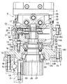
11は油圧モータ5(モータ軸5A)の回転を減速する遊星歯車式の減速装置で、該減速装置11は、後述のハウジング12、リングギヤ14、各遊星歯車減速機構17,21、出力軸25、上側軸受28、下側軸受29、与圧リング30等により構成されている。
【0024】
12は筒状のハウジングで、該ハウジング12は、軸方向に延びる円筒部12Aと、該円筒部12Aの下側に一体形成された大径なフランジ部12Bとにより、全体として段付き円筒状に形成されている。そして、ハウジング12のフランジ部12Bは、ボルト13を用いて旋回フレーム3上に固着されている。
【0025】
ここで、ハウジング12を構成する円筒部12Aの内周側には、後述の上側軸受28が取付けられる軸受取付孔12Cと、後述の下側軸受29が取付けられる軸受取付孔12Dとが、上,下に離間して設けられている。
【0026】
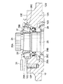
一方、ハウジング12の軸方向一側(上側)の端面は、後述のリングギヤ14が取付けられる取付面12Eとなり、該取付面12Eは、軸受取付孔12Cを取囲む環状な平面として形成されている。そして、取付面12Eは、図2に示すように、後述する与圧リング30(分割リング31)の下面から寸法Lだけ軸方向下側に離間している。また、取付面12Eには、周方向に離間して後述のボルト16が螺入される複数個の雌ねじ孔12F(1個のみ図示)が螺設されている。
【0027】
14はハウジング12の上端側に配設された筒状のリングギヤで、該リングギヤ14は、軸方向に延びる円筒部14Aと、該円筒部14Aの上側の内周面に全周に亘って形成された内歯14Bとにより大略構成されている。そして、円筒部14Aの上端側には、径方向外側に張出したフランジ部14Cが設けられ、該フランジ部14Cには、ボルト15を用いて油圧モータ5が固着される構成となっている。
【0028】
一方、円筒部14Aの下端側には、径方向内側に張出した環状の内向き突起14Dが設けられ、該内向き突起14Dの下面は、ハウジング12の取付面12Eに取付けられる端面となる取付面14Eとなっている。ここで、内向き突起14Dの内周側は、ハウジング12に形成された軸受取付孔12Cの孔径とほぼ等しい孔径を有する軸受嵌合孔14Fとなり、該軸受嵌合孔14Fの内周面は、後述の上側軸受28を構成する外輪28Aの外周面に嵌合する構成となっている。また、内向き突起14Dには、ハウジング12の取付面12Eに螺設された各雌ねじ孔12Fと対応する位置に、ボルト16が挿通される複数個のボルト挿通孔14G(1個のみ図示)が穿設されている。
【0029】
そして、リングギヤ14は、内向き突起14Dの取付面14Eをハウジング12の取付面12Eに当接させ、各ボルト挿通孔14Gに挿通したボルト16を各雌ねじ孔12Fに螺入することにより、上側軸受28の外周側に位置してハウジング12の取付面12E上に固着される構成となっている。
【0030】
17はリングギヤ14内に収容された1段目の遊星歯車減速機構で、該遊星歯車減速機構17は、油圧モータ5のモータ軸5Aにスプライン結合された太陽歯車18と、該太陽歯車18とリングギヤ14の内歯14Bとに噛合し、太陽歯車18の周囲を自転しつつ公転する複数の遊星歯車19(1個のみ図示)と、これら各遊星歯車19を回転可能に支持するキャリア20とにより大略構成されている。
【0031】
21は遊星減速歯車機構17の下側に位置してリングギヤ14内に収容された2段目の遊星歯車減速機構で、該遊星歯車減速機構21は、遊星歯車減速機構17のキャリア20にスプライン結合された太陽歯車22と、該太陽歯車22とリングギヤ14の内歯14Bとに噛合し、太陽歯車22の周囲を自転しつつ公転する複数の遊星歯車23(1個のみ図示)と、これら各遊星歯車23を回転可能に支持するキャリア24とにより大略構成されている。
【0032】
そして、2段目の遊星歯車減速機構21のキャリア24は、後述する出力軸25の雄スプライン26に噛合(スプライン結合)し、各遊星歯車減速機構17,21は、油圧モータ5の回転を2段減速することにより、出力軸25に大きなトルクを伝達するものである。また、キャリア24の下面には、リングギヤ14をハウジング12に固定するボルト16の頭部との干渉を防ぐため、該頭部と対応する位置に上向きに凹設された環状の逃げ溝24Aが設けられている(図2参照)。
【0033】
25はハウジング12内を軸方向に伸長して設けられた出力軸で、該出力軸25は、上側軸受28、下側軸受29を介してハウジング12に回転可能に取付けられ、各遊星歯車減速機構17,21によって減速された油圧モータ5の回転を出力するものである。
【0034】
ここで、出力軸25の軸方向の一側(上側)には、ハウジング12の取付面12Eから上方に突出する雄スプライン26が一体に設けられている。そして、雄スプライン26は、2段目(最終段)の遊星歯車減速機構21のキャリア24に噛合している。
【0035】
一方、出力軸25の下端側には、ハウジング12から下方に突出するピニオン27が一体に設けられている。そして、ピニオン27は、旋回輪1の内歯1Dに噛合し、出力軸25の回転を旋回輪1(内輪1A)に伝達するものである。また、出力軸25のうち雄スプライン26よりも下側の部位には、後述の各分割リング31が挿入される溝部25Aが全周に亘って凹設され、該溝部25Aの外径は、雄スプライン26の外径(歯先径)よりも小径に形成されている。
【0036】
28は雄スプライン26よりも下側に位置して出力軸25とハウジング12との間に設けられた上側軸受を示し、29は上側軸受28から下方に離間して出力軸25とハウジング12との間に設けられた下側軸受を示している。そして、これら上側軸受28と下側軸受29とは、ハウジング12に対して出力軸25を回転可能に支持するものである。
【0037】
ここで、上側軸受28は、図2に示すように、ハウジング12に形成された軸受取付孔12Cの内周面に圧入ばめ、すきまばめ等の手段によって嵌合された外輪28Aと、出力軸25の外周面にすきまばめ、圧入ばめ等の手段によって嵌合された内輪28Bと、外輪28Aと内輪28Bとの間に設けられた複数の転動体としての円錐ころ28Cとを備えた円錐ころ軸受により構成されている。
【0038】
一方、下側軸受29は、ハウジング12に形成された軸受取付孔12Dの内周面に圧入ばめ、すきまばめ等の手段によって嵌合された外輪29Aと、出力軸25の外周面にすきまばめ、圧入ばめ等の手段によって嵌合された内輪29Bと、外輪29Aと内輪29Bとの間に設けられた複数の転動体としての円錐ころ29Cとを備えた円錐ころ軸受により構成されている。
【0039】
ここで、図4等に示すように、上側軸受28を構成する外輪28Aは、ハウジング12の軸受取付孔12Cに嵌合された状態で、ハウジング12の取付面12Eから寸法Sだけ上方(出力軸25の雄スプライン26側)に突出している。これにより、図6に示すように、ハウジング12の取付面12Eにリングギヤ14を取付けるときに、該リングギヤ14の内向き突起14Dに形成した軸受嵌合孔14Fの内周面が、取付面12Eから突出した外輪28Aの外周面に嵌合し、リングギヤ14を径方向に位置決めすることができる。これにより、上側軸受28と下側軸受29とによって支持された出力軸25の軸中心線と、リングギヤ14の軸中心線とをほぼ同一の軸中心線O−O上に配置することができる構成となっている。
【0040】
30は出力軸25の雄スプライン26と上側軸受28の内輪28Bとの間に設けられた与圧リングで、該与圧リング30は、上側軸受28の内輪28B、円錐ころ28C、外輪28Aを軸方向に与圧すると共に、上側軸受28に対して出力軸25を軸方向に抜止めするものである。そして、与圧リング30は、図3等に示すように、2枚の分割リング31,31と、結束リング32とにより構成されている。
【0041】
ここで、各分割リング31は、半円弧状のプレートとして構成され、出力軸25の雄スプライン26と上側軸受28の内輪28Bとの間に、出力軸25の径方向から挿入されるものである。そして、図4等に示すように、分割リング31は、その内周面が出力軸25の溝部25Aに当接するまで径方向に挿入され、上面が雄スプライン26の下面に当接し、下面が上側軸受28の内輪28Bの上面に当接することにより、上側軸受28を軸方向に与圧している。
【0042】
一方、結束リング32は、1枚の環状のプレートとして構成され、出力軸25の雄スプライン26と上側軸受28の内輪28Bとの間に挿入された各分割リング31の外周面に嵌合することにより、該各分割リング31を一体に結束するものである。そして、結束リング32の上面は、遊星歯車減速機構21のキャリア24の下面に僅かな隙間をもって対面し、結束リング32の下面は、上側軸受28の内輪28Bの上面に当接している。
【0043】
本実施の形態による減速装置11は上述の如き構成を有するもので、旋回装置4が作動して油圧モータ5のモータ軸5Aが回転すると、このモータ軸5Aの回転が、減速装置11の遊星歯車減速機構17,21によって2段減速され、この減速された回転が出力軸25に伝わることにより、ピニオン27は大きなトルクをもって回転する。
【0044】
そして、ピニオン27が旋回輪1の内輪1Aに設けた内歯1Dと噛合しつつ内輪1Aに沿って公転し、このピニオン27の公転力が、ハウジング12を介して旋回フレーム3に伝わることにより、該旋回フレーム3を丸胴2上で旋回させることができる。
【0045】
ここで、本実施の形態による減速装置11は、ハウジング12の上端側に、与圧リング30から寸法Lだけ軸方向下側に離間した取付面12Eを設け、上側軸受28の外輪28Aを、ハウジング12の取付面12Eから寸法Sだけ上方に突出させることにより、組立作業の作業性が向上できるようになっており、以下、この減速装置11の組立作業について説明する。
【0046】
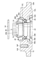
まず、例えば図4に示すように、ハウジング12の軸受取付孔12Cに上側軸受28の外輪28Aを嵌合させ、ハウジング12の軸受取付孔12Dに下側軸受29の外輪29Aを嵌合させた後、下側軸受29の内輪29Bと上側軸受28の内輪28Bとに出力軸25を嵌合させる。このとき、上側軸受28の外輪28Aの上端側は、ハウジング12の取付面12Eから上方に突出し、出力軸25の雄スプライン26と溝部25Aとは、上側軸受28の内輪28Bを通じて取付面12Eよりも上方に突出する。
【0047】
次に、出力軸25の雄スプライン26と上側軸受28の内輪28Bとの間に、出力軸25の径方向から各分割リング31を挿入し、該分割リング31の内周面を、出力軸25の溝部25Aに当接させる。これにより、分割リング31の上面が雄スプライン26の下面に当接すると共に、下面が上側軸受28の内輪28Bの上面に当接し、上側軸受28を軸方向に与圧することができる。
【0048】
このように、本実施の形態では、ハウジング12に上側軸受28と下側軸受29とを介して出力軸25を取付けたときに、該出力軸25の雄スプライン26と溝部25Aとを、ハウジング12の取付面12Eよりも上方に突出させることができる。このため、出力軸25の雄スプライン26と上側軸受28の内輪28Bとの間に径方向から各分割リング31を挿入する作業を、ハウジング12の外側(上側)で広い作業スペースをもって容易に行うことができる。従って、例えば従来技術のように、ハウジングによって囲まれた狭隘な作業スペース内で与圧リングを挿入する作業を行なう場合に比較して、各分割リング31を挿入するときの作業性を向上させることができる。
【0049】
そして、図5に示すように、出力軸25の雄スプライン26と上側軸受28の内輪28Bとの間に2枚の分割リング31,31を挿入した後、各分割リング31の外周面に、雄スプライン26側から結束リング32を挿嵌し、該結束リング32の下面を、上側軸受28の内輪28Bの上面に当接させる。これにより、各分割リング31が、結束リング32によって一体に結束され、これら分割リング31、結束リング32からなる与圧リング30により、上側軸受28を軸方向に与圧すると共に、上側軸受28に対して出力軸25を軸方向に抜止めすることができる。
【0050】
このようにして、与圧リング30を用いて上側軸受28を軸方向に与圧した後、図6に示すように、ハウジング12の取付面12Eに、リングギヤ14を構成する内向き突起14Dの取付面14Eを当接させる。このとき、リングギヤ14の内向き突起14Dに形成した軸受嵌合孔14Fの内周面が、取付面12Eから上方に突出した上側軸受28の外輪28Aの外周面に嵌合することにより、リングギヤ14は、上側軸受28の外輪28Aによって径方向に位置決めされる。
【0051】
この状態で、リングギヤ14のボルト挿通孔14Gにボルト16を挿通し、該ボルト16をハウジング12の雌ねじ孔12Fに螺入することにより、リングギヤ14を、上側軸受28の外周側でハウジング12の取付面12Eに取付けることができる。
【0052】
次に、遊星歯車減速機構21の各遊星歯車23と遊星歯車減速機構17の各遊星歯車19とを、リングギヤ14の内歯14Bに噛合させつつ、該各遊星歯車減速機構21,17をリングギヤ14内に組込み、遊星歯車減速機構21のキャリア24を、出力軸25の雄スプライン26に噛合させる。
【0053】
そして、リングギヤ14内に各遊星歯車減速機構21,17を組込んだ後、リングギヤ14のフランジ部14Cにボルト15を用いて油圧モータ5を取付け、該油圧モータ5のモータ軸5Aを、遊星歯車減速機構17の太陽歯車18に噛合させることにより、図1に示す如くの減速装置11を組立てることができる。
【0054】
ここで、本実施の形態では、上側軸受28を構成する外輪28Aの上端側を、ハウジング12の取付面12Eから寸法Sだけ上方に突出させ、リングギヤ14の内向き突起14Dには、外輪28Aの外周面に嵌合する軸受嵌合孔14Fを設ける構成としている。このため、軸受嵌合孔14Fの内周面が、取付面12Eから突出した外輪28Aの外周面に嵌合することにより、上側軸受28の外輪28Aを利用してリングギヤ14を径方向に位置決めすることができる。
【0055】
これにより、上側軸受28と下側軸受29とによって支持された出力軸25の軸中心線と、リングギヤ14の軸中心線とをほぼ同一の軸中心線O−O上に配置することができる。この結果、減速装置11の作動時に、リングギヤ14の内歯14Bと各遊星歯車19,23とを適正に噛合させることができるので、これら各遊星歯車19,23が早期に摩耗するのを抑えることができ、また、出力軸25を支持する上側軸受28、下側軸受29等の寿命が低下するのを抑えることができ、減速装置11の信頼性を高めることができる。
【0056】
なお、上述した実施の形態では、2段の遊星歯車減速機構17,21を備えた減速装置11を例に挙げて説明したが、本発明はこれに限るものではなく、例えば1段、または3段以上の遊星歯車減速機構を備えた減速装置にも適用することができる。
【0057】
また、上述した実施の形態では、上側軸受28と下側軸受29とを円錐ころ軸受により構成した場合を例示している。しかし、本発明はこれに限るものではなく、例えば円筒ころ軸受、玉軸受等の他の軸受によって構成してもよい。
【0058】
さらに、上述した実施の形態では、減速装置11を油圧ショベルの旋回装置に適用した場合を例に挙げたが、本発明はこれに限らず、例えば油圧ショベル等の下部走行体に搭載される走行装置、あるいは油圧クレーン等に搭載されるロープウインチ等にも適用することができる。
【0059】
【発明の効果】
以上詳述した如く、請求項1の発明によれば、軸受の外輪をハウジングの取付面よりも突出させて配置し、リングギヤの軸方向他側の内周面を、軸受の外輪の外周面によって位置決めする構成としている。このため、ハウジングの取付面にリングギヤを取付けるときに、該リングギヤの軸方向他側の内周面を、ハウジングの取付面から突出した軸受の外輪の外周面によって径方向に位置決めすることができるので、軸受によって支持された出力軸の軸中心線と、リングギヤの軸中心線とをほぼ同軸上に配置することができる。この結果、減速装置の作動時にリングギヤと各遊星歯車とを適正に噛合させることができるので、各遊星歯車が早期に摩耗したり、各軸受の寿命が低下するのを抑えることができ、減速装置の信頼性を高めることができる。
【0060】
また、請求項2の発明によれば、出力軸の雄スプラインと軸受との間に与圧リングを設ける構成としている。このため、ハウジングに軸受を介して出力軸を取付けたときに、該出力軸の雄スプラインを、ハウジングの取付面から軸方向一側に突出させることができる。これにより、出力軸の雄スプラインと軸受との間に与圧リングを取付ける作業を、ハウジングの外側で広い作業スペースをもって行うことができ、この与圧リングを取付けるときの作業性を向上させることができる。
【0061】
さらに、請求項3の発明によれば、与圧リングを、出力軸の雄スプラインと軸受の内輪との間に出力軸の径方向から挿入される複数枚の分割リングと、該各分割リングの外周側に嵌合する結束リングとにより構成している。これにより、各分割リングを、出力軸の径方向から雄スプラインと軸受の内輪との間に挿入した後、該各分割リングの外周側に結束リングを嵌合させるだけで、軸受の内輪を軸方向に与圧する作業を容易に行うことができる。
【図面の簡単な説明】
【図1】本発明に係る減速装置の実施の形態を油圧ショベルの旋回装置に適用した状態で示す縦断面図である。
【図2】図1中のハウジングの取付面、リングギヤ、上側軸受、与圧リング等の要部を拡大して示す要部拡大断面図である。
【図3】与圧リングを構成する2枚の分割リングと結束リングとを、出力軸と共に示す分解斜視図である。
【図4】出力軸の雄スプラインと上側軸受の内輪との間に分割リングを挿入する作業状態を示す断面図である。
【図5】2枚の分割リングの外周面に結束リングを挿嵌する作業状態を示す断面図である。
【図6】ハウジングの取付面にリングギヤを取付ける作業状態を示す断面図である。
【符号の説明】
5 油圧モータ(回転源)
12 ハウジング
12E 取付面
14 リングギヤ
17,21 遊星歯車減速機構
19,23 遊星歯車
20,24 キャリア
25 出力軸
26 雄スプライン
28 上側軸受(軸受)
28A 外輪
28B 内輪
28C 円錐ころ(転動体)
30 与圧リング
31 分割リング
32 結束リング[0001]
TECHNICAL FIELD OF THE INVENTION
The present invention relates to a reduction gear suitable for use in, for example, a swing device mounted on a construction machine such as a hydraulic shovel or a hydraulic crane, a traveling device, a rope winch mounted on a hydraulic crane or the like.
[0002]
[Prior art]
2. Description of the Related Art In general, construction machines such as a hydraulic shovel and a hydraulic crane are generally configured by a lower traveling body that can run on its own and an upper revolving body that is pivotally mounted on the lower traveling body. The traveling device mounted on the lower traveling structure and the revolving device mounted between the lower traveling structure and the upper revolving structure are provided with a planetary gear type reduction device for increasing the output of the rotation source. (For example, see Patent Document 1).
[0003]
[Patent Document 1]
Japanese Utility Model Publication No. 4-89150
[0004]
Here, the reduction gear transmission according to the prior art includes a housing formed in a cylindrical shape and one side (upper side) in the axial direction serving as a mounting surface, and a rotation source provided in a cylindrical shape and provided on one side in the axial direction. A ring gear having the other side (lower side) mounted on the mounting surface of the housing, a two-stage planetary gear reduction mechanism accommodated in the ring gear and reducing the rotation of the rotation source, and extending in the housing in the axial direction. An output shaft provided with a male spline that is provided on one side in the axial direction and meshes with the carrier at the last stage of the planetary gear reduction mechanism, and a bearing in which the outer ring is fitted on the inner peripheral side of the housing and the inner ring is fitted on the output shaft. And a pressurizing ring provided between the male spline of the output shaft and the bearing to pressurize the bearing in the axial direction.
[0005]
In this reduction gear transmission, the rotation of a rotation source such as a hydraulic motor is reduced by a planetary gear reduction mechanism and transmitted to an output shaft to rotate the output shaft with a large torque.
[0006]
Here, when assembling the above-described reduction gear transmission, after assembling the output shaft to the housing via the upper and lower bearings, a semicircular arc is formed between the male spline of the output shaft and the inner ring of the upper bearing. A pressurizing ring made up of two split rings is inserted from the radial direction of the output shaft. Thus, the pressurizing ring pressurizes the upper bearing in the axial direction and prevents the output shaft from coming off in the axial direction, and the output shaft can be rotatably supported on the housing by each bearing.
[0007]
Next, the carrier of the second stage planetary gear reduction mechanism is assembled to the male spline of the output shaft, and the carrier of the first stage planetary gear reduction mechanism is assembled to the sun gear of the second stage planetary gear reduction mechanism. wear. Then, while the ring gear is meshed with the planet gears of each planetary gear reduction mechanism, the ring gear is arranged on the mounting surface of the housing, and a hydraulic motor serving as a rotation source is mounted above the ring gear, and these hydraulic motors and the ring gear are connected. Secure it to the mounting surface of the housing using bolts.
[0008]
[Problems to be solved by the invention]
However, in the speed reducer according to the prior art, the ring gear is merely mounted on the mounting surface of the housing using bolts, so that when the speed reducer is assembled, the output shaft mounted on the housing via the upper and lower bearings is required. It is difficult to arrange the shaft centerline and the ring gear shaft centerline on the same axis, and the two are often displaced in the radial direction.
[0009]
If the shaft center line of the output shaft and the shaft center line of the ring gear are misaligned, the planetary gear meshing with the ring gear may be worn out at the time of operation of the reduction gear, or the bearings of the bearings supporting the output shaft may be damaged. There is a problem that the life is shortened and the reliability of the reduction gear is impaired.
[0010]
On the other hand, in the conventional reduction gear transmission, the mounting surface of the housing for mounting the ring gear is provided at a position protruding above the outer ring of the upper bearing. For this reason, when the output shaft is assembled to the housing via the upper and lower bearings at the time of assembling the above-described reduction gear, the periphery of the upper bearing is surrounded by the housing.
[0011]
Therefore, the work of inserting the pressurizing ring from the radial direction of the output shaft between the male spline of the output shaft and the inner ring of the upper bearing must be performed in a narrow work space surrounded by the housing. There is a problem that workability when inserting the pressure ring is significantly reduced.
[0012]
SUMMARY OF THE INVENTION The present invention has been made in view of the above-described problems of the related art, and can arrange a shaft center line of an output shaft and a shaft center line of a ring gear substantially coaxially, and improve workability during assembly. It is an object of the present invention to provide a reduction gear device capable of performing the above-described operation.
[0013]
[Means for Solving the Problems]
In order to solve the above-described problem, the present invention provides a housing formed in a cylindrical shape and one side in the axial direction serving as a mounting surface, a housing formed in a cylindrical shape and provided with a rotation source on one side in the axial direction, and an axial other side. A ring gear having a side mounted on the mounting surface of the housing, a one or more stages of planetary gear reduction mechanisms accommodated in the ring gear and reducing the rotation of a rotation source, and a shaft extending in the housing in the axial direction. One side in the direction is an output shaft that is a male spline that meshes with the final stage carrier that constitutes the planetary gear reduction mechanism, and an outer ring is fitted to the inner peripheral side of the housing with the rolling element interposed, and the inner ring is connected to the output shaft. The present invention is applied to a speed reducer including a fitted bearing.
[0014]
The invention according to
[0015]
With this configuration, when the ring gear is mounted on the mounting surface of the housing, the inner peripheral surface on the other axial side of the ring gear can be radially positioned by the outer ring of the bearing protruding from the mounting surface of the housing. it can. Thereby, the shaft center line of the output shaft supported by the bearing and the shaft center line of the ring gear can be arranged substantially coaxially.
[0016]
According to a second aspect of the present invention, a pressurizing ring for pressurizing the bearing in the axial direction is provided between the male spline of the output shaft and the bearing.
[0017]
With this configuration, when the output shaft is mounted on the housing via the bearing, the male spline of the output shaft projects from the mounting surface of the housing to one side in the axial direction. For this reason, the work of installing the pressurizing ring between the male spline of the output shaft and the bearing can be performed with a wide working space outside the housing.
[0018]
According to a third aspect of the present invention, the pressurizing ring includes a plurality of split rings inserted between the male spline of the output shaft and the inner ring of the bearing from the radial direction of the output shaft, and is fitted on the outer peripheral side of each of the split rings. And a binding ring that binds them together.
[0019]
With this configuration, after each split ring is inserted between the male spline and the inner ring of the bearing from the radial direction of the output shaft, only by fitting the binding ring to the outer peripheral side of each split ring, The operation of preloading the bearing in the axial direction can be easily performed.
[0020]
BEST MODE FOR CARRYING OUT THE INVENTION
Hereinafter, an embodiment of a speed reducer according to the present invention applied to a turning device of a hydraulic shovel will be described in detail with reference to FIGS. 1 to 6 as an example.
[0021]
In the drawing,
[0022]
Reference numeral 4 denotes a revolving device provided between the lower traveling structure and the upper revolving structure. The revolving device 4 transmits a rotational force to the revolving
[0023]
[0024]
[0025]
Here, on the inner peripheral side of the
[0026]
On the other hand, an end surface on one axial side (upper side) of the
[0027]
[0028]
On the other hand, on the lower end side of the
[0029]
Then, the
[0030]
[0031]
[0032]
The
[0033]
An
[0034]
Here, on one side (upper side) of the
[0035]
On the other hand, a
[0036]
[0037]
Here, as shown in FIG. 2, the
[0038]
On the other hand, the
[0039]
Here, as shown in FIG. 4 and the like, the
[0040]
[0041]
Here, each
[0042]
On the other hand, the binding
[0043]
The
[0044]
Then, the
[0045]
Here, the
[0046]
First, as shown in FIG. 4, for example, after the
[0047]
Next, each
[0048]
As described above, in the present embodiment, when the
[0049]
Then, as shown in FIG. 5, after inserting two split rings 31, 31 between the
[0050]
After pressurizing the
[0051]
In this state, the
[0052]
Next, while each
[0053]
Then, after assembling the planetary
[0054]
Here, in the present embodiment, the upper end side of the
[0055]
Thus, the shaft center line of the
[0056]
In the above-described embodiment, the
[0057]
In the above-described embodiment, the case where the
[0058]
Furthermore, in the above-described embodiment, the case where the
[0059]
【The invention's effect】
As described above in detail, according to the first aspect of the present invention, the outer ring of the bearing is disposed so as to protrude from the mounting surface of the housing, and the inner peripheral surface on the other axial side of the ring gear is formed by the outer peripheral surface of the outer ring of the bearing. Positioning is performed. Therefore, when the ring gear is mounted on the mounting surface of the housing, the inner peripheral surface on the other axial side of the ring gear can be radially positioned by the outer peripheral surface of the outer ring of the bearing protruding from the mounting surface of the housing. The shaft center line of the output shaft supported by the bearing and the shaft center line of the ring gear can be arranged substantially coaxially. As a result, the ring gear and each planetary gear can be properly meshed with each other during operation of the reduction gear, so that each planetary gear can be prevented from being worn out early or the life of each bearing can be reduced, and the reduction gear can be reduced. Reliability can be improved.
[0060]
Further, according to the invention of
[0061]
Further, according to the third aspect of the present invention, the pressurizing ring is inserted between the male spline of the output shaft and the inner ring of the bearing from the radial direction of the output shaft, and a plurality of split rings are provided. And a binding ring fitted on the outer peripheral side. Thus, after each split ring is inserted between the male spline and the inner ring of the bearing from the radial direction of the output shaft, the inner ring of the bearing is rotated by simply fitting the binding ring to the outer peripheral side of each split ring. The operation of prestressing in the direction can be easily performed.
[Brief description of the drawings]
FIG. 1 is a longitudinal sectional view showing a state where an embodiment of a reduction gear transmission according to the present invention is applied to a turning device of a hydraulic shovel.
FIG. 2 is an enlarged sectional view showing a main part of a mounting surface of a housing, a ring gear, an upper bearing, a pressurizing ring and the like in FIG. 1 in an enlarged manner.
FIG. 3 is an exploded perspective view showing two split rings and a binding ring constituting a pressurizing ring together with an output shaft.
FIG. 4 is a sectional view showing a working state of inserting a split ring between a male spline of an output shaft and an inner ring of an upper bearing.
FIG. 5 is a cross-sectional view showing an operation state in which a binding ring is inserted into an outer peripheral surface of two split rings.
FIG. 6 is a cross-sectional view showing a state in which a ring gear is mounted on a mounting surface of a housing.
[Explanation of symbols]
5 Hydraulic motor (rotation source)
12 Housing
12E mounting surface
14 Ring gear
17,21 planetary gear reduction mechanism
19,23 planetary gear
20, 24 career
25 Output shaft
26 Male Spline
28 Upper bearing (bearing)
28A Outer ring
28B Inner ring
28C tapered roller (rolling element)
30 Pressurized ring
31 Split ring
32 Binding Ring
Claims (3)
前記軸受の外輪は前記ハウジングの取付面よりも突出させて配置し、前記リングギヤの軸方向他側の内周面は前記軸受の外輪の外周面によって位置決めする構成としたことを特徴とする減速装置。A housing formed in a cylindrical shape and one side in the axial direction serving as a mounting surface; a ring gear formed in a cylindrical shape and provided with a rotation source on one side in the axial direction and the other side in the axial direction mounted on a mounting surface of the housing; A planetary gear reduction mechanism of one or more stages accommodated in the ring gear to reduce the rotation of the rotation source, and a planetary gear reduction mechanism that is provided extending in the housing in the axial direction and one side in the axial direction is provided. An output shaft that is a male spline that meshes with the carrier of the last stage to be configured, and a bearing in which an outer ring is fitted on the inner peripheral side of the housing with the rolling element interposed and an inner ring is fitted on the output shaft. In the reduction gear
The reduction gear transmission is characterized in that the outer ring of the bearing is arranged so as to protrude from the mounting surface of the housing, and the inner peripheral surface of the other side in the axial direction of the ring gear is positioned by the outer peripheral surface of the outer ring of the bearing. .
Priority Applications (1)
| Application Number | Priority Date | Filing Date | Title |
|---|---|---|---|
| JP2003027425A JP2004239320A (en) | 2003-02-04 | 2003-02-04 | Reduction gear |
Applications Claiming Priority (1)
| Application Number | Priority Date | Filing Date | Title |
|---|---|---|---|
| JP2003027425A JP2004239320A (en) | 2003-02-04 | 2003-02-04 | Reduction gear |
Publications (1)
| Publication Number | Publication Date |
|---|---|
| JP2004239320A true JP2004239320A (en) | 2004-08-26 |
Family
ID=32955159
Family Applications (1)
| Application Number | Title | Priority Date | Filing Date |
|---|---|---|---|
| JP2003027425A Pending JP2004239320A (en) | 2003-02-04 | 2003-02-04 | Reduction gear |
Country Status (1)
| Country | Link |
|---|---|
| JP (1) | JP2004239320A (en) |
Cited By (5)
| Publication number | Priority date | Publication date | Assignee | Title |
|---|---|---|---|---|
| JP2009222111A (en) * | 2008-03-14 | 2009-10-01 | Jtekt Corp | Rolling bearing device and rolling device for continuous casting machine |
| JP2009228820A (en) * | 2008-03-24 | 2009-10-08 | Jtekt Corp | Rolling bearing device and roll device for continuous casting machine |
| JP2011163478A (en) * | 2010-02-11 | 2011-08-25 | Hitachi Constr Mach Co Ltd | Power transmission device |
| JP2014169760A (en) * | 2013-03-04 | 2014-09-18 | Sumitomo Heavy Ind Ltd | Reduction gear |
| US10508727B2 (en) | 2016-08-31 | 2019-12-17 | Spx Flow, Inc. | Drive system and drive sub-assembly for driving a shaft |
-
2003
- 2003-02-04 JP JP2003027425A patent/JP2004239320A/en active Pending
Cited By (5)
| Publication number | Priority date | Publication date | Assignee | Title |
|---|---|---|---|---|
| JP2009222111A (en) * | 2008-03-14 | 2009-10-01 | Jtekt Corp | Rolling bearing device and rolling device for continuous casting machine |
| JP2009228820A (en) * | 2008-03-24 | 2009-10-08 | Jtekt Corp | Rolling bearing device and roll device for continuous casting machine |
| JP2011163478A (en) * | 2010-02-11 | 2011-08-25 | Hitachi Constr Mach Co Ltd | Power transmission device |
| JP2014169760A (en) * | 2013-03-04 | 2014-09-18 | Sumitomo Heavy Ind Ltd | Reduction gear |
| US10508727B2 (en) | 2016-08-31 | 2019-12-17 | Spx Flow, Inc. | Drive system and drive sub-assembly for driving a shaft |
Similar Documents
| Publication | Publication Date | Title |
|---|---|---|
| US8029400B2 (en) | Center crank eccentrically oscillating speed reducer | |
| JP5356462B2 (en) | Turning structure of industrial robot using eccentric rocking type reducer | |
| JP5023606B2 (en) | Electric drive | |
| JP5156961B2 (en) | Reduction gear | |
| JP5832413B2 (en) | Wheel drive device | |
| EP2735462A1 (en) | Wheel drive unit | |
| JP3842525B2 (en) | Planetary gear reducer | |
| JP2004239320A (en) | Reduction gear | |
| JP4908444B2 (en) | Reduction gear | |
| JP2003222205A (en) | Reduction gear | |
| JP2004245356A (en) | Planetary gear reduction gear | |
| JP5820298B2 (en) | Power transmission device and assembly method thereof | |
| JP2002147545A (en) | Hydraulic driving reduction gear | |
| JP4632852B2 (en) | Industrial robot swivel structure | |
| JP2739909B2 (en) | Planetary gear reducer | |
| JPS6116440Y2 (en) | ||
| JP2014058996A (en) | Deceleration device | |
| JP2000337457A (en) | Reduction gear | |
| JPH06249298A (en) | Planetary reduction gear | |
| JP2005061579A (en) | Swing device for construction machinery | |
| JP6131171B2 (en) | Simple planetary gear reducer | |
| JP2002168325A (en) | Reduction gear | |
| JP4837508B2 (en) | Power transmission device for construction machinery | |
| JP2002195389A (en) | Speed reducer | |
| JP3603014B2 (en) | Hydraulic motor |
Legal Events
| Date | Code | Title | Description |
|---|---|---|---|
| A621 | Written request for application examination |
Free format text: JAPANESE INTERMEDIATE CODE: A621 Effective date: 20050722 |
|
| A977 | Report on retrieval |
Free format text: JAPANESE INTERMEDIATE CODE: A971007 Effective date: 20080131 |
|
| A131 | Notification of reasons for refusal |
Free format text: JAPANESE INTERMEDIATE CODE: A131 Effective date: 20080212 |
|
| A521 | Written amendment |
Free format text: JAPANESE INTERMEDIATE CODE: A523 Effective date: 20080410 |
|
| A02 | Decision of refusal |
Free format text: JAPANESE INTERMEDIATE CODE: A02 Effective date: 20080930 |