JP2004236811A - Ankle supporter - Google Patents
Ankle supporter Download PDFInfo
- Publication number
- JP2004236811A JP2004236811A JP2003028415A JP2003028415A JP2004236811A JP 2004236811 A JP2004236811 A JP 2004236811A JP 2003028415 A JP2003028415 A JP 2003028415A JP 2003028415 A JP2003028415 A JP 2003028415A JP 2004236811 A JP2004236811 A JP 2004236811A
- Authority
- JP
- Japan
- Prior art keywords
- tubular member
- sole
- applying means
- belt
- tension applying
- Prior art date
- Legal status (The legal status is an assumption and is not a legal conclusion. Google has not performed a legal analysis and makes no representation as to the accuracy of the status listed.)
- Pending
Links
Images


Landscapes
- Professional, Industrial, Or Sporting Protective Garments (AREA)
- Orthopedics, Nursing, And Contraception (AREA)
Abstract
Description
【0001】
【発明の属する技術分野】
本発明は、足関節における内反または外反捻挫等の外傷の発生予防、再発予防、治療や、拘縮に対する矯正やリハビリテーションのために足首に固定して用いられる医療用、スポーツ用の足関節サポーターに関する。
【0002】
【従来の技術】
足関節における捻挫等の外傷の発生予防、再発予防、治療や、先天性または後天性の疾患が原因で起こる拘縮に対する矯正、リハビリテーションには種々の方法があるが、現在主として、ギプス、副木、テーピングテープ、バンデージ、サポーター等が使用され、場合によってはこれらの複数のものが併用される。これらの各手段にはそれぞれの特徴があり、使用者の患部の状態や使用される状況等によって選択される。その中で、特にサポーターは次のような利点をもつことから、外傷の有用な発生予防、再発予防、治療の手段として様々な場面で利用されている。まず、サポーターは、装着するのに例えばギプス、テーピングテープのように、ある程度の熟練した技術またはそれを有する補助者を特別必要とせず、簡単にしかも短時間に装着ができる。また、患部の状態によって長期的に着用するのが好ましい場合には、サポーターは、連続使用に対する安定性、耐久性がテーピングテープやバンデージに比べ優れており、その結果使用に際してのランニングコストも少なくてすむ。
【0003】
現在使用されている足関節サポーターとしては種々のものがあるが、その1つとして足関節周囲を覆う筒状体と、その外表面に設置され足関節を締め付け固定するベルトからなるサポーターがある。この種のサポーターの具体的な構造として、足関節周囲を覆う筒状体、筒状体の内踝外表面に1端が取り付けられ、足底部から足背部を通り踵部上部に至る伸縮性ベルトを備えたサポーター(例えば、特許文献1参照。)、足関節の上方および下方周囲を覆う筒状体、筒状体の外側面から足底部を通り反対側の外側面まで延びるベルト、筒状体の後部のアキレス腱に対応する部分から足底部を取り巻いて外側面まで延びるベルトを備えたサポーター(例えば、特許文献2参照。)、足関節周囲を覆う筒状体、筒状体の内側の踝を覆う板状部材、板状部材の下部または筒状体の足底部に連結され足底部を通り筒状体の外側面まで回るベルトを備えたサポーター(例えば、特許文献3参照。)等がある。
【0004】
これらのサポーターは、いずれも足背部または足底部周囲を捲回するベルトや支持プレートにより、足関節を中心に特定の方向から力をかけて足関節を固定しようとするものであるが、足底部の動きに対して、サポーターのずれ、よれを十分に抑制すると共に足底部の安定性を十分に維持できるものではなかった。即ち足底部はサポーターとの接触面積が広く、使用者の全体重が集中する部分である上、一般に凹凸のあるアーチ形状を有しているため、サポーターのずれが非常に起こりやすい部分であるが、従来のサポーターはそれを抑制するのに特段有利な構造を備えていなかった。その結果、足底部で発生したサポーターのずれ、よれは、足の動きによりさらにその周辺部に広がるため、適切な位置からずれた位置でサポーターを固定することになり、サポーター本来の機能を十分に発揮することができない。また、この種のサポーターは一般に足関節周囲をより強固に固定するため複数のベルトを使用し、2重、3重に患部を締め付けることが行われるが、足関節サポーターの装着に慣れていない人や高齢者あるいは手先が不自由な人にとっては操作が煩雑になるばかりか、不適切な位置にベルトを固定してしまう可能性もある。
【0005】
また、足底部を安定させる方法としては、足関節全体を覆う筒状体の足底部に対応する部分に足底板を一体的に取り付けたサポーターが提案されている(例えば、特許文献4、特許文献5、参照。)。しかしながら、足底部の形状は個人差が大きいため、この種のサポーターを使用する場合には、使用者に応じて適当な足底板を調整する手間がかかるし、靴を履いて使用する場合には靴との相性も考慮する必要があった。また、足底板を筒状体に一体的に取り付けることで、足底板と筒状体とのずれは防止するという利点はあるが、サポーターそのものを患部からずれないようにする特段の構成は持っていないため、仮に足底板が使用者にフィットするものだとしても、使用と共に徐々にサポーターがずれる可能性があった。
【0006】
更に、脳卒中片麻痺や腓骨神経麻痺等の障害で損なわれた下肢の機能を矯正するため、足に装着した第1の装着体と大腿に装着した第2の装着体との間に伸縮体を掛け渡し、伸縮体の弾性力により足先を上方に持ち上げるようにした装具も提案されている(例えば、引用文献6)。この装具によれば、足の動きを封じることなく足先を上方に持ち上げることができ、歩行の際に足先が床や段差に引っ掛かるのを防止することができるが、2つの装着体を使用するため装着が面倒で、また伸縮体は両装着体間に局部的な力を加えることになるため、損傷した足の機能を十分に保護し得るものではない。又、麻痺による障害では足先が下がると共に、足は内反が起こり易くなり、そのため捻挫等を引き起こす可能性があるが、このサポーターでは内反を十分に抑制する機能を備えていない。
【0007】
【特許文献1】
実開平3−101930号公報(第2〜6頁、第1図、第2図)
【特許文献2】
特表平7−503879号公報(第6〜7頁、図1、図2)
【特許文献3】
特開平11−9754号公報(第2〜3頁、図1、図2)
【特許文献4】
特開平7−184944号公報(第2〜3頁、図1、図2)
【特許文献5】
特開2001−192902号公報(第2〜3頁、図1)
【特許文献6】
特開平9−313553号公報(第2〜5頁、図1〜6)
【0008】
【発明が解決しようとする課題】
本発明の課題は、足関節を適切な位置にずれが起きないように固定し、安定した支持と適切な圧迫を加えることができ、しかも、操作が簡単で扱い易い足関節サポーターを提供することにある。特に、足の底背屈の動きを過度に妨げることなく、内反又は外反の動きを十分に抑制し、足底部の安定性を維持する足関節サポーターを提供することを課題とする。
【0009】
【課題を解決するための手段】
上述の課題を解決するために、本発明においては、踝、足底部の一部および足背部の一部を覆う筒状部材と、筒状部材の一方の外側面から筒状部材の足底部に対応する部分を通り筒状部材の他方の外側面に至る方向に張力を与える張力付与手段とを備え、張力付与手段の筒状部材の一方の外側面に位置する一端の幅とその一端が設置される筒状部材の幅の比が0.4:1.0〜1.0:1.0の範囲であり、張力付与手段により足前部に上向きの力を加え得るようにする。
【0010】
また本発明においては、踝、足底部の一部および足背部の一部を覆う筒状部材と、筒状部材の足底部に対応する部分から筒状部材の足底部に対応する部分を通り筒状部材のいずれか一方の外側面に至る方向に張力を与える張力付与手段とを備え、張力付与手段の筒状部材の足底部に対応する部分に位置する一端の幅とその一端が設置される筒状部材の幅の比が0.4:1.0〜1.0:1.0の範囲であり、張力付与手段により足前部に上向きの力を加え得るようにする。
【0011】
張力付与手段の筒状部材の一方の外側面に位置する一端の幅、又は張力付与手段の筒状部材の足底部に対応する部分に位置する一端の幅は、他端の幅より広く形成するのが好ましい。
【0012】
筒状部材は、天然繊維、化学繊維よりなる織布、編布、不織布、パイル生地や、フォーム材料などを単独または任意に選択組み合わせて形成することができる。その具体的な素材としては、例えば、綿、毛、ウール、レーヨン、アクリル、ポリアミド、ポリエステル、ポリウレタン、ポリ塩化ビニリデン等の繊維を適宜組み合わせてなる、経編みまたは緯編み布のジャージ生地、パワーネットのような弾性糸混紡編物、ダブルラッシェル生地の立体編物等がある。さらに、これらの生地とゴム発泡体(クロロプレンゴム、天然ゴム、ブチルゴム、スチレン・ブタジエンゴム 、イソプレンゴム等)、ウレタン発泡体(圧縮ウレタン)等のフォーム材料を積層した複合材料を用いることができる。
【0013】
筒状部材は上述のような素材を連続した1枚の生地から形成することができるが、適当な大きさに裁断したものを縫製や接着によりつなぎ合わせて形成することもできる。特に、足背上部や踵部のような凹凸の多い部位では体表面との追従性が必要であり、適度な圧迫性や操作性を向上させるために伸縮性の生地を部分的または全面に用いるのが好ましい。この筒状部材の生地の伸縮性は、その生地に用いる繊維の特性やその混紡の割合、生地同士の組合せパターン等により自由に調整することができる。なお、表面生地がポリアミド、ポリエステル、ポリ塩化ビニリデン等の素材でパイル状にしたものは面ファスナとして利用でき、筒状部材同士または筒状部材と他の部材間での着脱やそれらの位置調節に有利である。
【0014】
筒状部材は踝と足底部の一部および足背部の一部を覆うように適当な大きさに略筒状に形成することができるが、この筒状部材は、最初から布帛を筒状に縫製したもののほか、この筒状部材の一部または全部に、開放部分を設けたものを使用することができる。開放部分は、前方側(足背側)または後方側(アキレス腱側)、側方側のいずれの箇所に設けても良く、開放の切れ込みは直線状、曲線状、またはその両方を組み合わせた形状を用いることができる。開放部分を設ける場合には、開放した一方の側片を他方の側片に面ファスナ等で係着して筒状に形成できるようにする。このような開放部分を設けることにより、面ファスナ等の係着の仕方を調節することができ、個人差のある患部に対し最も適切な圧迫力を加えることができる。筒状部材は少なくとも踝と足底部の一部および足背部の一部を覆っていればよく、疾患の状態や使用される状況を考慮して、下腿部の一部をも覆い得るようにしたり、適宜スリットや孔を開けて通気性を向上させたりすることができる。
【0015】
筒状部材に設置される張力付与手段としては特に限定されないが、具体的には、伸縮性または非伸縮性の帯状の材料の1端を筒状部材の外側面または筒状部材の足底部に対応する部分に取り付け、他端を反対側の外側面に引上げられるように設置する方法、筒状部材の外側面または筒状部材の足底部に対応する部分から筒状部材の足底部に対応する部分を通り筒状部分の反対側の外側面の方向に至る領域に、筒状部材の生地より強い弾性をもつ材料を設置する方法等がある。弾性をもつ材料の設置方法としては、その弾性材料の形態により適宜選択でき、例えば、帯状、シート状のものであれば筒状部材の生地の上から(生地が積層構造である場合はその内部に)縫着、接着、溶着等により取り付け、糸状のものであれば筒状部材へ縫い込むことで張力を付与させる。また、弾力性を有する合成樹脂を液状で生地へ含浸、塗布し、その後樹脂を乾燥させる方法も用いることができる。勿論、これらの弾力性のある材料そのもので、筒状部材の上記領域の一部または全部を構成し、張力を付与させてもよい。張力付与手段として特に好ましくは、帯状の材料を設置する方法で、帯状の先端に面ファスナ等の係合手段を取り付け筒状部材と着脱自在にすることで、圧迫や固定の力を調節ができるようになる。それに、帯状部材に使用する材料の性質を適宜選択することでも容易に圧迫や固定の力を変えることができるので、幅広い患者層に適応可能なサポーターとなる。つまり、非伸縮性の材料または弾力性に富む材料を使用すれば、肢位を強固にかつ安定的に固定する場合に有利であり、伸縮性の材料または弾力性に乏しい材料を使用したものであれば、スポーツ選手やリハビリテーションを行う患者等の患部にある程度の可動性が求められ場合に適用できる。
【0016】
また、張力付与手段は、足底部にバランス良く力をかけ、足底部を全体的に支持、安定させるために、筒状部材の外側面または筒状部材の足底部に対応する部分に取り付けられる1端の幅とそれが設置される筒状部材の幅の比が0.4:1.0〜1.0:1.0の範囲であることが好ましく、0.5:1.0〜0.8:1.0の範囲であることがさらに好ましい。張力付与手段の1端の幅が筒状部材の幅に対して0.4以下であると、足底部の安定性が得られ難くなると共に、局所的に圧力がかかり易くなるので使用者に痛みを生じさせたり、筒状部材が磨耗し易くなる可能性がある。また、1.0以上、即ち張力付与手段の幅が筒状部材の幅より広いと、サポーター全体のかさが増え、装着感が悪化すると共に、経済的にも不利である。なお、張力付与手段が、足前部に上向きの力を効果的に加え、内反又は外反の動きを十分に抑制するために、筒状部材の外側面に1端を取り付ける場合には、他端を筒状部材の他方の外側面において前記1端の設置される筒状部材の位置より高い位置に設置すること、また筒状部材の足底部に対応する部分に1端を取り付け、筒状部材の足底部に対応する部分を通り筒状部材のいずれか一方の外側面に至る方向に張力付与手段を設ける場合には、張力付与手段が少なくとも足底の半分以上の部分を通り得る位置に1端を設置し、他端を筒状部材の外側面の足底より高い位置に設置することが好ましい。さらにこの張力付与手段は、内反又は外反の動きのきっかけとなる踵部の動きに対し、その側方の動揺を抑制するために、足底部の踵部近傍に対応する位置を通ることが好ましい。この際、張力付与手段の筒状部材の外側面または筒状部材の足底部に対応する部分に位置する1端の幅は、他端の幅より広く形成されるか、その1端から他端に向かって概ね幅が狭くなっていくよう形成される。このようにすることで、幅広に形成した張力付与手段の1端近傍は足底部を十分支持することができ、一方、それよりも幅を狭くした他端はサポーターと足の追従性を向上させると共に、必要以上に足の動きを制限しないので装着感が向上する。特に、張力付与手段として帯状部材を使用した場合は、その先端幅が狭くなっていれば持ち易く、帯状部材の位置調節の操作がやり易い。さらに、この帯状部材を複数のベルト部材を接合し形成することもできる。ベルト部材は特に張力をかける必要がある部分(例えば、踵や爪先近傍等)にその1端を設置し、他端はばらばらにならないよう1つにまとめて接合する。また、複数のベルト部材に使用する材料を性質の異なるもので形成すれば、加える張力を部分的に変えることもでき、患部の状態に合わせた適用が可能となる。ベルト部材の本数は特に限定されないが、2本を略V字形状に形成したものが好ましく、2本のベルト部材間に間隙ができるので、筒状部材を覆わない部分ができ、足との追従性が向上すると共に、経済的にも有利である。また、ベルト部材は適宜スリットや孔を開ければ、通気性を確保し、足との追従性をさらに高めることができる。
【0017】
張力付与手段として帯状部材を使用する場合、帯状部材の筒状部材への取り付け部分近傍に当て辺を設けることができる。当て辺を設置することで、筒状部材にしわやよれが発生し難くなり、また、帯状部材の筒状部材への取り付けを補強することができる。当て辺は少なくとも帯状部材の筒状部材への取り付け部分を被覆していればよく、形状や大きさは限定されないが、筒状部材の軸方向と平行するように設置されるのが好ましい。当て辺としては、筒状部材に使用する材料と同様のものを使用することができる。
【0018】
さらに、張力付与手段が帯状部材であれば、筒状部材の足底部に対応する部分から左右に延び、足背部に対応する部分上で8の字状に交差して踵部に対応する部分の上部の近傍に至るように巻き付け固定し得るよう帯状部材を形成してもよく、この帯状部材を筒状部材の回りに固定することにより、底屈、背屈を共に制限でき、より強い固定力が得られる。この帯状部材は、2本の帯状部材の1端をそれぞれ足底部に取り付け、左右から立ち上げて他端を筒状部材上に着脱可能に形成するようにしても良いし、1本の帯状部材の中央部を筒状部材の足底部に対応する部分に取り付け、この足底部に対応する部分の左右から立ち上げて両端を筒状部材上に着脱可能に形成するようにしても良い。帯状部材は好ましくは伸縮性で、その端部には筒状部材に着脱できるよう面ファスナ等の係合手段を設けることが好ましい。
【0019】
張力付与手段の表面に滑り止め性を付与させることで、サポーターを装着した状態で靴を履いても靴の中でサポーターがずれ難く、適切な支持、固定を保つことができる。また、靴を脱いだ状態でも床面やスリッパとも滑り難くなり、高齢者のように足腰が弱い人が滑って転倒することも予防することができる。滑り止め性を付与させる手段としては、従来からの方法を利用でき、特にエラストマー材料を種々の形態に加工したものを使用するのが好ましい。具体的には、エラストマー材料を糸状、シート状、フォーム状等の形態に加工したものを張力付与手段の表面の一部または全部に設置したり、液状にしたエラストマー材料を張力付与手段の一部または全部に塗布したりして、滑り止め性を付与する。エラストマー材料として好ましくは、天然ゴム、イソプレンゴム、塩素化ゴム、ブタジエンゴム、ブチルゴム、スチレンゴム、スチレン−ブタジエンゴム、クロロプレンゴム、ニトリルゴム、アクリルゴム、多硫化ゴム、シリコーンゴム、ポリエチレンゴム、フッ素ゴム、ポリウレタンゴム、ABS、エピクロルヒドリンゴム等の原料ゴムや、ポリスチレン系、ポリオレフィン系、ポリウレタン系、ポリエステル系、ポリアミド系、ポリ塩化ビニル系、エチレン−酢酸ビニル系等の熱可塑性エラストマーが使用できる。
【0020】
足関節の内反や外反を抑制する目的で、筒状部材の両側面に金属またはプラスチックから形成される支持体を設けてもよい。この支持体の筒状部材への取り付け方法としては、筒状部材にポケットを設けその内部に挿入したり、筒状部材生地内部に縫込んだり、筒状部材の外側表面に面ファスナ等により着脱自在に取り付けることができる。
【0021】
【発明の実施の形態】
次に本発明の実施の形態を、図面に示す実施例について説明する。
【0022】
図1において、aは左側面図、bは右側面図、cは正面図、dは筒状部材を開放状態にした正面図である。1は筒状部材で、下腿部の一部から踝と足底部の一部および足背部の一部を覆うよう筒状に形成され、装着しやすくするため前開き式に形成され、その後方の踵部に対応する部分Pに開口2を備え、筒状部材の足背部に対応する部分Q、足底部に対応する部分Rは舟状骨、立方骨を覆い得る個所まで延びている。筒状部材1は下腿部に対応する部分Sの一方の側に2個の面ファスナ3、4、足背部に対応する部分Qの一方の側に面ファスナ5が設けられ、筒状部材1を装着して前開きの部分を閉じ、これらの面ファスナを用いて人体上に固定することができる。筒状部材1は表面にポリアミド、ポリウレタンからなるフレンチパイル、芯にポリウレタン発泡体、裏面にポリエステルジャージの3種類の生地を接着により積層させたものを用いて構成され、その表面側の生地により面ファスナを着脱できるようになっている。
【0023】
筒状部材1の外側面には、張力付与手段として織ゴム製の帯状部材6の1端7が、その1端の幅W1と1端7が設置される筒状部材の幅Lの比が0.4:1.0〜1.0:1.0の範囲になるよう固定され、帯状部材6は外側面から筒状部材の足底部に対応する部分Rを通り筒状部材の反対側の外側面の方向に延び、足背部に対応する部分Q上を通り、踵部に対応する部分Pの上部の近傍に至り巻き付けることができる長さを有しており、その先端8には面ファスナ9が設けられ、筒状部材1のフレンチパイル面に係合できるようになっている。帯状部材6は、その1端7の幅W1を他端の先端8の幅W2より幅広に形成すると共に、1端7から他端8に向かって徐々に幅を狭くするように形成する。10は帯状部材6の筒状部材1への取り付け部分に設置される当て辺で、筒状部材1と同様の材料を適当な大きさにカットし、筒状部材1の軸方向と平行するように縫着されている。
【0024】
次に図1の足関節サポーターの装着方法を図2を利用して説明する。先ず筒状部材1の前を開いて装着者の足をその踵部31が開口2に嵌り込むような位置に置き、筒状部材1の前を閉じ、各面ファスナ3、4、5を備えた側を他方の側の上に重ねて面ファスナ3、4、5を筒状部材1上に係着し、下腿部32から足背部33の一部、足底部34の一部が筒状部材1により包まれるように固定する(aの状態)。次いで、筒状部材1の外側面から延びる帯状部材6を足底部34から、足背部33の頂上を添わせ、反対側に引き伸ばし、踵部の上部近傍で面ファスナにより筒状部材1に係着する(bの状態)。このようにして、筒状部材1は足背部と足底部の各一部に確実に固定された上で帯状部材6が筒状部材1の一方の外側面から足底部34を通り、他方の外側面に至り、筒状部材上に係着されることにより、筒状部材1の足底部に対応する部分が帯状部材6により足底部に押し付けられるから筒状部材6が足からずれることがなく、しかも足前部に対し上向きの力が加わる。
【0025】
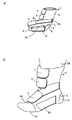
図3、図4は本発明の異なる実施例の、aは左側面図、bは装着状態における斜視図であり、図1と同等部分には同符号を付してある。図3の実施例は図1の実施例に対し、張力付与手段として帯状部材11が2本のベルト部材12、13を略V字形状に接合し構成される点が異なっている。即ち2本のベルトの1端14、15が筒状部材1の外側面に取り付けられ、ベルトの他端が互いに接合され面ファスナ16で筒状部材1上に係着とできるようになっている。装着に当たっては、図1、図2の実施例で説明した係着方法と同様な方法で適用する。図4の実施例は図1の実施例に対し、帯状部材17が2本のベルト部材18、19を略V字形状に接合し構成される点と、その帯状部材17を足底部の中央部分に2本取り付ける点が異なっている。この2本のベルト状部材18、19の足底部に固定する部分の幅W1とその固定される部分の筒状部材17の幅Lとの比は同様に0.4:1.0〜1.0:1.0の範囲になるように選ぶのが好ましい。装着に当たっては、足底部の中央から延びる2本の帯状部材17を足背部上に添わせ、足背部の頂上で互いに8の字に交差するようにして反対側に引き伸ばし、踵部の上部近傍で面ファスナ20により筒状部材1上に係着する。
【0026】
上述の実施例の図1、図3では帯状部材を足の内反を予防する方向に取り付けた例を示したが、帯状部材を図1、図3とは反対側の外側面に取り付け足の外反を予防するようにすることも可能で、その場合の帯状部材の取り付け位置以外の構成については基本的に変るところはない。
【0027】
図5、図6はそれぞれ本発明のさらに異なる実施例の、aは左側面図、bは装着状態における斜視図であり、図1と同等部分には同符号を付してある。これらの実施例は図1の実施例に対し、張力付与手段の構成が異なっている。即ち図5の実施例における張力付与手段21は、筒状部材の外側面から足底部に対応する部分を通り、反対側の外側面の方向に延び、足背部に対応する部分を通り、踵部に対応する部分の上部の近傍に至る領域に、筒状部材の生地より強い弾性を持つ生地を縫着する構成になっている。張力付与手段に用いる生地の弾性の強さは、本サポーターの使用者の疾患の状態や使用される状況(スポーツやリハビリテーション等)を考慮して適宜選択することができる。又、図6の実施例における張力付与手段22は、筒状部材の外側面から足底部に対応する部分を通り、反対側の外側面の方向に延び、足背部に対応する部分を通り、踵部に対応する部分の上部の近傍に至る領域を、筒状部材の他の領域より弾性の強い編み組織にすることで構成されている。弾性の強い編み組織を形成する方法としては、ポリウレタン繊維のような弾性を有する材料で編みを行うか、編みに使用する糸の打ち込み本数を他の領域より増やし形成することができる。この方法によれば、筒状部材に他の材料を重ね合わせしなくてもよいので、張力付与手段の厚みを抑えることができる。これら図5、図6による実施例は、張力付与手段として帯状部材を使ったときに要する張力の強さ調節が特段いらないので、簡単に着脱でき、また、使用時ごとに張力のかかり具合を気にすることなく毎回一定の張力を得ることができる。
【0028】
以上述べた実施例においては、帯状部材の一端は筒状部材の一方の外側面又は筒状部材の足底部に対応する部分の中央に始まっているものを示したが、これらに限るものではない。筒状部材の足底部に対応する部分の任意の位置、即ち足底部の中央に限らず、中央からずれた任意の位置から始まって筒状部材の一方の外側面又は両外側面に至るように帯状部材を設けることができる。
【0029】
【発明の効果】
本発明によれば、筒状部材に足底部を覆う張力付与手段を備えることで、足底部と筒状部材生地とのずれを起こり難くすることができ、長時間使用しても安定した支持、固定を持続させることができる。又、足の底背屈の動きを過度に妨げる構成を有していないため、スポーツやリハビリテーションを行う場合には、足が本来持っている底背屈の機能を有効に使いつつ、内反又は外反の動きを十分に抑制し、足関節及び足底部の安定性を維持することができる。しかも、本体部分は筒状部材だけで、その外には必要最低限のベルトで確実に患部を固定するものであるから操作が簡単で扱い易く、素材の使用量を低減できるため経済的にも有利である。
【図面の簡単な説明】
【図1】本発明の実施例の、aは左側面図、bは右側面図、cは正面図、dは筒状部材を開放状態にした正面図である。
【図2】本発明の装着方法を説明するための斜視図である。
【図3】本発明の別の実施例の、aは左側面図、bは装着状態における斜視図である。
【図4】本発明のさらに別の実施例の、aは左側面図、bは装着状態における斜視図である。
【図5】本発明のさらに異なる実施例の、aは左側面図、bは装着状態における斜視図である。
【図6】本発明のさらに異なる実施例の、aは左側面図、bは装着状態における斜視図である。
【符号の説明】
1 筒状部材
2 開口
3 面ファスナ
4 面ファスナ
5 面ファスナ
6 帯状部材(張力付与手段)
7 帯状部材の1端
8 帯状部材の1端
9 面ファスナ
10 当て辺
11 帯状部材(張力付与手段)
12 ベルト部材
13 ベルト部材
14 ベルトの1端
15 ベルトの1端
16 面ファスナ
17 帯状部材(張力付与手段)
18 ベルト部材
19 ベルト部材
20 面ファスナ
21 張力付与手段
22 張力付与手段
31 踵部
32 下腿部
33 足背部
34 足底部
P 踵部に対応する部分
Q 足背部に対応する部分
R 足底部に対応する部分
S 下腿部に対応する部分[0001]
TECHNICAL FIELD OF THE INVENTION
The present invention relates to a medical or sports ankle joint which is fixed to an ankle for prevention of occurrence, relapse prevention and treatment of trauma such as varus or valgus sprain in an ankle joint, and correction or rehabilitation for contracture. About supporters.
[0002]
[Prior art]
There are various methods for the prevention, recurrence prevention and treatment of trauma such as sprains in the ankle joint, and correction and rehabilitation for contractures caused by congenital or acquired diseases. , A taping tape, a bandage, a supporter, and the like are used, and a plurality of these may be used in some cases. Each of these means has its own characteristics, and is selected according to the condition of the affected part of the user, the situation of use, and the like. Among them, the supporter has the following advantages, and is therefore used in various situations as a useful means for preventing the occurrence of traumatic injury, preventing recurrence and treating. First, the supporter can be mounted easily and in a short time without requiring special skills or an auxiliary person having the same, for example, a cast or a taping tape. In addition, when it is preferable to wear the supporter for a long time depending on the condition of the affected part, the supporter has better stability and durability for continuous use than taping tape and bandage, and as a result, running cost at the time of use is low. Yes.
[0003]
There are various types of ankle supporters currently used. One of them is a tubular body that covers the periphery of the ankle joint, and a supporter that is provided on the outer surface and includes a belt that fastens and fixes the ankle joint. As a specific structure of this type of supporter, a tubular body covering the circumference of the ankle joint, one end is attached to the outer surface of the inner and ankles of the tubular body, and an elastic belt extending from the sole to the upper part of the heel through the back of the foot. A supporter (for example, see Patent Document 1), a tubular body covering the upper and lower periphery of the ankle joint, a belt extending from the outer surface of the tubular body through the sole to the outer surface on the opposite side, and a tubular body. A supporter provided with a belt extending from the portion corresponding to the Achilles tendon at the rear to the outside surface around the sole (for example, see Patent Document 2), a tubular body covering around the ankle joint, and covering the ankle inside the tubular body There is a plate-like member, a supporter provided with a belt connected to the lower part of the plate-like member or the sole of the tubular body and passing through the sole to the outer surface of the tubular body (for example, see Patent Document 3).
[0004]
All of these supporters try to fix the ankle joint by applying force from a specific direction around the ankle joint by using a belt or support plate that winds around the back of the foot or the sole. However, it was not possible to sufficiently prevent the supporter from shifting and swaying, and to sufficiently maintain the stability of the sole. In other words, the sole has a large contact area with the supporter, and is a part where the overall weight of the user is concentrated, and because it generally has an uneven arch shape, it is a part where the displacement of the supporter is very likely to occur. However, conventional supporters did not have a particularly advantageous structure to suppress it. As a result, the shift and twist of the supporter that occurred at the sole part spread further around the foot due to the movement of the foot, so the supporter will be fixed at a position shifted from the appropriate position, and the supporter's original function will be sufficiently Can not demonstrate. In addition, this type of supporter generally uses a plurality of belts to more firmly fix the circumference of the ankle joint, and tightens the affected part two or three times. However, those who are not accustomed to wearing the ankle supporter In addition, for an elderly person or a person with a disability, the operation becomes complicated, and the belt may be fixed at an inappropriate position.
[0005]
Further, as a method of stabilizing the sole, a supporter in which a sole plate is integrally attached to a portion corresponding to the sole of a tubular body that covers the entire ankle joint has been proposed (for example,
[0006]
Furthermore, in order to correct the function of the lower limb damaged by disorders such as stroke hemiplegia and peroneal nerve palsy, an elastic body is inserted between the first wearing body attached to the foot and the second wearing body attached to the thigh. There has also been proposed an orthosis in which the toes are lifted upward by the elastic force of the stretchable body (for example, Patent Document 6). According to this brace, the toes can be lifted upward without blocking the movement of the feet, and the toes can be prevented from being caught on the floor or a step when walking, but two wearing bodies are used. Therefore, the wearing is troublesome, and since the elastic body applies a local force between the two wearing bodies, the function of the damaged foot cannot be sufficiently protected. In addition, in the case of an injury due to paralysis, the tip of the foot is lowered, and the foot is liable to varus, which may cause a sprain. However, this supporter does not have a function to sufficiently suppress the varus.
[0007]
[Patent Document 1]
Japanese Utility Model Laid-Open No. 3-101930 (
[Patent Document 2]
Japanese Patent Publication No. 7-503879 (
[Patent Document 3]
JP-A-11-9754 (pages 2-3, FIGS. 1 and 2)
[Patent Document 4]
JP-A-7-184944 (pages 2-3, FIGS. 1 and 2)
[Patent Document 5]
JP-A-2001-192902 (pages 2-3, FIG. 1)
[Patent Document 6]
JP-A-9-313553 (
[0008]
[Problems to be solved by the invention]
An object of the present invention is to provide an ankle supporter which can fix an ankle joint at an appropriate position so as not to be displaced, apply stable support and appropriate compression, and is easy to operate and easy to handle. It is in. In particular, it is an object of the present invention to provide an ankle supporter that sufficiently suppresses varus or valgus movement without excessively hindering the sole dorsiflexion movement of the foot and maintains the stability of the sole.
[0009]
[Means for Solving the Problems]
In order to solve the above-mentioned problems, in the present invention, the ankle, a tubular member covering a part of the sole and a part of the back of the foot, and from one outer surface of the tubular member to the sole of the tubular member. Tension applying means for applying tension in a direction reaching the other outer surface of the cylindrical member through the corresponding portion, and the width of one end of the cylindrical member of the tension applying means located on one outer surface and the one end thereof are installed. The ratio of the width of the cylindrical member to be formed is in the range of 0.4: 1.0 to 1.0: 1.0, and an upward force can be applied to the forefoot by the tension applying means.
[0010]
Further, in the present invention, the tubular member covering the ankle, a part of the sole, and a part of the back of the foot, and a part corresponding to the sole of the tubular member passing from the part corresponding to the sole of the tubular member. Tension applying means for applying tension in a direction reaching one of the outer surfaces of the tubular member, and the width and one end of one end located at a portion corresponding to the sole of the tubular member of the tension applying means are installed. The ratio of the width of the tubular member is in the range of 0.4: 1.0 to 1.0: 1.0, and an upward force can be applied to the forefoot by the tension applying means.
[0011]
The width of one end located on one outer surface of the tubular member of the tension applying means, or the width of one end located on a portion corresponding to the sole of the tubular member of the tension applying means is formed wider than the width of the other end. Is preferred.
[0012]
The tubular member can be formed by using a woven fabric, a knitted fabric, a nonwoven fabric, a pile fabric, a foam material, or the like made of natural fibers and chemical fibers alone or in any combination. Specific examples thereof include, for example, warp knit or weft knitted jersey fabric, power net made by appropriately combining fibers such as cotton, wool, wool, rayon, acrylic, polyamide, polyester, polyurethane, and polyvinylidene chloride. And three-dimensional knitted fabric of double Raschel fabric. Further, a composite material obtained by laminating a foam material such as a rubber foam (chloroprene rubber, natural rubber, butyl rubber, styrene / butadiene rubber, isoprene rubber, etc.) or a urethane foam (compressed urethane) can be used.
[0013]
The tubular member can be formed from a single piece of continuous cloth of the above-described materials, but can also be formed by cutting and cutting the pieces to an appropriate size by sewing or bonding. In particular, in areas with many irregularities such as the upper back of the foot and the heel, it is necessary to follow the body surface, and a stretchy cloth is used partially or entirely to improve moderate compression and operability. Is preferred. The elasticity of the fabric of the tubular member can be freely adjusted by the characteristics of the fibers used in the fabric, the blend ratio thereof, the combination pattern of the fabrics, and the like. In addition, a surface fabric made of a pile of a material such as polyamide, polyester, or polyvinylidene chloride can be used as a hook-and-loop fastener, and is used for attaching and detaching between cylindrical members or between a cylindrical member and another member, and adjusting their positions. It is advantageous.
[0014]
The tubular member can be formed in a substantially cylindrical shape with an appropriate size so as to cover the ankle, a part of the sole, and a part of the back of the foot. In addition to the sewn one, a part of or the entirety of the tubular member provided with an open portion can be used. The open part may be provided on the anterior side (dorsal side) or the posterior side (Achilles tendon side) or on any side side, and the cut of the opening may be straight, curved, or a combination of both. Can be used. When an open portion is provided, one open side piece is attached to the other side piece with a hook-and-loop fastener or the like so that it can be formed into a cylindrical shape. By providing such an open portion, the manner of attachment of the hook-and-loop fastener or the like can be adjusted, and the most appropriate compression force can be applied to the affected part having individual differences. The tubular member only needs to cover at least a part of the ankle, a part of the sole, and a part of the sole of the foot, and can cover a part of the lower leg in consideration of a disease state or a use condition. Alternatively, slits or holes may be formed as appropriate to improve air permeability.
[0015]
The tension applying means installed on the tubular member is not particularly limited, but specifically, one end of a stretchable or non-stretchable strip-shaped material is attached to the outer surface of the tubular member or the sole of the tubular member. Attach to the corresponding portion and install so that the other end can be pulled up to the opposite outer surface, from the portion corresponding to the outer surface of the tubular member or the sole of the tubular member to the sole of the tubular member There is a method of installing a material having a higher elasticity than the material of the tubular member in a region passing through the portion and extending in the direction of the outer surface opposite to the tubular portion. The method of installing the elastic material can be appropriately selected depending on the form of the elastic material. For example, if the material is a band-like or sheet-like material, the material is placed on the cylindrical material (when the material has a laminated structure, 2) Attachment is performed by sewing, bonding, welding, or the like, and a thread-like material is sewn into a tubular member to apply tension. Further, a method of impregnating and applying a synthetic resin having elasticity to a cloth in a liquid state, and then drying the resin can also be used. Of course, these elastic materials themselves may constitute part or all of the above-mentioned region of the tubular member, and may be applied with tension. Particularly preferably, the tension applying means is a method of installing a band-shaped material, and by attaching and detaching an engaging means such as a hook-and-loop fastener to the end of the band so as to be detachable from the cylindrical member, it is possible to adjust the pressing and fixing force. Become like In addition, since the pressure and the fixing force can be easily changed by appropriately selecting the properties of the material used for the band-shaped member, the supporter can be applied to a wide range of patients. In other words, the use of a non-stretchable material or a material with a high elasticity is advantageous in firmly and stably fixing the limb position, and a stretchy material or a material with a low elasticity is used. If there is, a certain degree of mobility is required for an affected part such as an athlete or a patient performing rehabilitation, and the present invention can be applied.
[0016]
Further, the tension applying means is attached to the outer surface of the tubular member or a portion corresponding to the sole of the tubular member in order to apply a balanced force to the sole and to support and stabilize the sole as a whole. The ratio of the width of the end to the width of the tubular member on which it is installed is preferably in the range of 0.4: 1.0 to 1.0: 1.0, preferably 0.5: 1.0 to 0.1. More preferably, the ratio is in the range of 8: 1.0. If the width of one end of the tension applying means is 0.4 or less with respect to the width of the tubular member, it becomes difficult to obtain stability of the sole portion, and it becomes easy for the local pressure to be applied. And the cylindrical member may be easily worn. On the other hand, if it is 1.0 or more, that is, if the width of the tension applying means is wider than the width of the cylindrical member, the bulk of the entire supporter increases, which deteriorates the feeling of wearing and is economically disadvantageous. In addition, when one end is attached to the outer surface of the tubular member, the tension applying means effectively applies an upward force to the forefoot and sufficiently suppresses varus or valgus movement. The other end is installed at a position higher than the position of the tubular member at the one end on the other outer surface of the tubular member, and one end is attached to a portion corresponding to the sole of the tubular member, When the tension applying means is provided in a direction passing through a portion corresponding to the sole of the tubular member and reaching one of the outer surfaces of the tubular member, the position at which the tension applying means can pass through at least a half or more portion of the sole. It is preferable that one end is installed and the other end is installed at a position higher than the sole on the outer surface of the tubular member. Further, this tension applying means may pass through a position corresponding to the vicinity of the heel portion of the sole, in order to suppress the lateral sway of the heel movement which triggers the varus or valgus movement. preferable. At this time, the width of one end located on the outer surface of the tubular member or the portion corresponding to the sole of the tubular member of the tension applying means is formed to be wider than the width of the other end, or from one end to the other end. Is formed so that the width generally decreases toward. By doing so, the vicinity of one end of the wide tension applying means can sufficiently support the sole portion, while the other end having a narrower width improves the followability between the supporter and the foot. At the same time, the feeling of wearing is improved because the movement of the foot is not unnecessarily restricted. In particular, when a belt-shaped member is used as the tension applying means, it is easy to hold the narrower end width, and the position of the belt-shaped member is easily adjusted. Further, the belt-shaped member may be formed by joining a plurality of belt members. One end of the belt member is installed in a portion that needs to be particularly tensioned (for example, near a heel or a toe), and the other end is joined together so as not to be separated. Further, if the materials used for the plurality of belt members are formed of materials having different properties, the applied tension can be partially changed, and the application according to the condition of the affected part can be performed. Although the number of belt members is not particularly limited, it is preferable that two belt members are formed in a substantially V-shape, and since a gap is formed between the two belt members, a portion that does not cover the tubular member is formed, so that the belt can follow. It is economically advantageous as well as improving the performance. In addition, if the belt member is appropriately provided with slits and holes, air permeability can be secured, and the ability to follow the foot can be further enhanced.
[0017]
When a belt-like member is used as the tension applying means, a contact side can be provided near a portion where the belt-like member is attached to the tubular member. By providing the contact side, wrinkles and warping are less likely to occur in the tubular member, and the attachment of the belt-shaped member to the tubular member can be reinforced. It is sufficient that the contact side covers at least the portion of the belt-shaped member attached to the tubular member, and the shape and size are not limited. However, it is preferable that the contact side is installed so as to be parallel to the axial direction of the tubular member. As the contact side, the same material as that used for the tubular member can be used.
[0018]
Furthermore, if the tension applying means is a belt-shaped member, the portion extending from left to right from the portion corresponding to the sole of the tubular member, crossing the figure of 8 on the portion corresponding to the back of the foot, and A band-shaped member may be formed so that the band-shaped member can be wound and fixed so as to reach the vicinity of the upper portion. By fixing the band-shaped member around the cylindrical member, both plantar flexion and dorsiflexion can be restricted, and a stronger fixing force can be obtained. Is obtained. This band-shaped member may be configured such that one end of each of the two band-shaped members is attached to the sole of the foot, and the band-shaped member is raised from the left and right, and the other end is detachably formed on the tubular member. May be attached to a portion corresponding to the sole of the tubular member, and the both ends may be detachably formed on the tubular member by rising from the left and right of the portion corresponding to the sole. The belt-shaped member is preferably elastic, and it is preferable to provide an engaging means such as a hook-and-loop fastener at an end thereof so that the belt-shaped member can be attached to and detached from the tubular member.
[0019]
By providing the surface of the tension applying means with a non-slip property, even if the shoe is worn while the supporter is attached, the supporter is unlikely to slip in the shoe, and appropriate support and fixation can be maintained. In addition, even when the shoes are taken off, the floor and the slippers are less likely to slip, and it is possible to prevent a person with weak legs such as the elderly from slipping and falling. As a means for imparting anti-slip properties, a conventional method can be used. In particular, it is preferable to use an elastomer material processed into various forms. Specifically, a material obtained by processing an elastomer material into a form such as a thread, a sheet, or a foam is installed on a part or all of the surface of the tension applying means, or a liquid elastomer material is partially applied to the tension applying means. Or, it is applied to all to impart anti-slip properties. Preferably as an elastomer material, natural rubber, isoprene rubber, chlorinated rubber, butadiene rubber, butyl rubber, styrene rubber, styrene-butadiene rubber, chloroprene rubber, nitrile rubber, acrylic rubber, polysulfide rubber, silicone rubber, polyethylene rubber, fluorine rubber Raw rubbers such as polyurethane rubber, ABS and epichlorohydrin rubber, and thermoplastic elastomers such as polystyrene, polyolefin, polyurethane, polyester, polyamide, polyvinyl chloride, and ethylene-vinyl acetate can be used.
[0020]
For the purpose of suppressing varus or valgus of the ankle joint, a support made of metal or plastic may be provided on both side surfaces of the tubular member. As a method of attaching the support to the tubular member, a pocket is provided in the tubular member, inserted into the inside, sewn into the fabric of the tubular member, or attached and detached to the outer surface of the tubular member by a hook-and-loop fastener or the like. Can be mounted freely.
[0021]
BEST MODE FOR CARRYING OUT THE INVENTION
Next, embodiments of the present invention will be described with reference to examples shown in the drawings.
[0022]
In FIG. 1, a is a left side view, b is a right side view, c is a front view, and d is a front view in which the tubular member is in an open state.
[0023]
On the outer surface of the
[0024]
Next, a method of mounting the ankle supporter of FIG. 1 will be described with reference to FIG. First, the front of the
[0025]
3 and 4 show different embodiments of the present invention, wherein a is a left side view, b is a perspective view in a mounted state, and the same parts as those in FIG. 1 are denoted by the same reference numerals. The embodiment of FIG. 3 is different from the embodiment of FIG. 1 in that a belt-shaped
[0026]
FIGS. 1 and 3 of the above-described embodiment show an example in which the band-shaped member is attached in a direction to prevent inversion of the foot. However, the band-shaped member is attached to the outer surface on the opposite side to FIGS. It is also possible to prevent eversion, and there is basically no change in the configuration other than the mounting position of the band-shaped member in that case.
[0027]
FIGS. 5 and 6 each show still another embodiment of the present invention, in which a is a left side view, b is a perspective view in a mounted state, and the same parts as those in FIG. These embodiments differ from the embodiment of FIG. 1 in the configuration of the tension applying means. That is, the
[0028]
In the embodiment described above, one end of the band-shaped member is shown as starting at one of the outer surface of the cylindrical member or the center of the portion corresponding to the sole of the cylindrical member, but is not limited thereto. . Arbitrary position of the portion corresponding to the sole of the tubular member, that is, not only at the center of the sole, but starting from any position deviated from the center and reaching one outer surface or both outer surfaces of the tubular member A strip can be provided.
[0029]
【The invention's effect】
According to the present invention, by providing the tubular member with a tension applying means for covering the sole portion, it is possible to prevent the displacement between the sole portion and the tubular member fabric, and to provide stable support even when used for a long time. Fixation can be sustained. In addition, because it does not have a configuration that excessively hinders the sole dorsiflexion movement of the foot, when performing sports or rehabilitation, effectively use the sole dorsiflexion function that the foot originally has, varus or The valgus movement can be sufficiently suppressed, and the stability of the ankle joint and the sole can be maintained. In addition, the main body is only a cylindrical member, and the affected part is securely fixed with the minimum necessary belt outside, so operation is easy and easy to handle, and the amount of material used can be reduced, so it is economical It is advantageous.
[Brief description of the drawings]
FIG. 1 is a left side view, b is a right side view, c is a front view, and d is a front view in a state where a tubular member is opened in an embodiment of the present invention.
FIG. 2 is a perspective view for explaining a mounting method of the present invention.
FIG. 3 is a left side view of another embodiment of the present invention, and b is a perspective view in a mounted state.
FIG. 4A is a left side view and FIG. 4B is a perspective view in a mounted state of still another embodiment of the present invention.
5A is a left side view and FIG. 5B is a perspective view in a mounted state of still another embodiment of the present invention.
6A is a left side view, and FIG. 6B is a perspective view in a mounted state, in still another embodiment of the present invention.
[Explanation of symbols]
1 tubular member
2 opening
3 side fastener
4 side fastener
5 hook and loop fastener
6 belt-shaped members (tension applying means)
7 One end of the strip
8 One end of the strip
Nine fasteners
10 Hitting edge
11 belt-shaped member (tension applying means)
12 Belt member
13 Belt member
14 One end of the belt
15 One end of the belt
16 fasteners
17 belt-shaped member (tension applying means)
18 Belt member
19 Belt member
20 fasteners
21 Tension applying means
22 Tension applying means
31 Heel
32 lower leg
33 feet back
34 sole
P The part corresponding to the heel
Q The part corresponding to the back of the foot
R The part corresponding to the sole
S The part corresponding to the lower leg
Claims (13)
Priority Applications (1)
| Application Number | Priority Date | Filing Date | Title |
|---|---|---|---|
| JP2003028415A JP2004236811A (en) | 2003-02-05 | 2003-02-05 | Ankle supporter |
Applications Claiming Priority (1)
| Application Number | Priority Date | Filing Date | Title |
|---|---|---|---|
| JP2003028415A JP2004236811A (en) | 2003-02-05 | 2003-02-05 | Ankle supporter |
Publications (1)
| Publication Number | Publication Date |
|---|---|
| JP2004236811A true JP2004236811A (en) | 2004-08-26 |
Family
ID=32955895
Family Applications (1)
| Application Number | Title | Priority Date | Filing Date |
|---|---|---|---|
| JP2003028415A Pending JP2004236811A (en) | 2003-02-05 | 2003-02-05 | Ankle supporter |
Country Status (1)
| Country | Link |
|---|---|
| JP (1) | JP2004236811A (en) |
Cited By (6)
| Publication number | Priority date | Publication date | Assignee | Title |
|---|---|---|---|---|
| JP2006305208A (en) * | 2005-05-02 | 2006-11-09 | Nippon Sigmax Kk | Ankle joint supporter |
| JP2007151663A (en) * | 2005-12-01 | 2007-06-21 | Alcare Co Ltd | Soft supporter, and manufacturing method for french pile for the same |
| WO2009144967A1 (en) * | 2008-05-26 | 2009-12-03 | Harada Masanori | Supporter structure for preventing or treating disease associated with deformity of foot |
| WO2010005861A2 (en) * | 2008-07-08 | 2010-01-14 | 3M Innovative Properties Company | Ankle support |
| JP2012000168A (en) * | 2010-06-15 | 2012-01-05 | Corporation Pearl Star:Kk | Correction strap and leg correction implement using this |
| JP2016003399A (en) * | 2014-06-13 | 2016-01-12 | ダイヤ工業株式会社 | clothing |
Citations (29)
| Publication number | Priority date | Publication date | Assignee | Title |
|---|---|---|---|---|
| JPS6316013U (en) * | 1986-07-17 | 1988-02-02 | ||
| JPS6357076A (en) * | 1986-08-27 | 1988-03-11 | 八島 成一 | Supporter |
| JPS63163826U (en) * | 1987-04-13 | 1988-10-26 | ||
| JPS6348255Y2 (en) * | 1984-03-05 | 1988-12-13 | ||
| JPH019547Y2 (en) * | 1983-08-18 | 1989-03-16 | ||
| JPH0279987U (en) * | 1988-12-08 | 1990-06-20 | ||
| JPH0370558A (en) * | 1989-08-10 | 1991-03-26 | Tokyo Eizai Kenkyusho:Kk | Covering outfit and preparation thereof |
| JPH03101930U (en) * | 1990-02-07 | 1991-10-23 | ||
| JPH04126520U (en) * | 1991-05-02 | 1992-11-18 | 日本シグマツクス株式会社 | knee joint supporter |
| JPH0622993A (en) * | 1992-04-30 | 1994-02-01 | Otto Bock Orthopaed Ind Besitz & Verwalt Kg | Heel joint corrector |
| JPH0620497Y2 (en) * | 1992-03-17 | 1994-06-01 | 日本シグマックス株式会社 | Ankle brace |
| JPH06319791A (en) * | 1993-05-17 | 1994-11-22 | Mitsubishi Rayon Co Ltd | Medical support |
| JPH07503879A (en) * | 1992-02-20 | 1995-04-27 | スミス アンド ネフュー インコーポレーテッド | orthopedic ankle orthosis |
| JPH07194649A (en) * | 1993-12-28 | 1995-08-01 | Iwao Kasahara | Knee supporter with wings |
| JPH0819560A (en) * | 1994-07-08 | 1996-01-23 | Pigeon Corp | Lumbago alleviating band |
| US5501659A (en) * | 1993-02-08 | 1996-03-26 | Smith & Nephew Donjoy, Inc. | Ankle brace |
| JP2534784Y2 (en) * | 1991-04-17 | 1997-05-07 | アルケア株式会社 | Ankle orthosis |
| JPH09294759A (en) * | 1996-05-07 | 1997-11-18 | Mamoru Tonami | Backache treatment belt |
| JPH09313553A (en) * | 1996-05-27 | 1997-12-09 | Hiroshi Okumura | Foot corrector |
| JPH1024055A (en) * | 1996-07-15 | 1998-01-27 | Ashisuto:Kk | Ankle fixing body |
| JPH10512461A (en) * | 1994-10-17 | 1998-12-02 | ロス,アイヴァー,イー. | Equipment for stabilizing the foot |
| JP3056231U (en) * | 1998-07-28 | 1999-02-12 | 博 宇土 | Lumbar orthosis |
| JPH11131306A (en) * | 1997-11-04 | 1999-05-18 | Terukazu Uchida | Belly supporter |
| JP2601089Y2 (en) * | 1993-05-31 | 1999-11-02 | アルケア株式会社 | Auxiliary anchor for ankle anchors |
| JPH11318963A (en) * | 1998-05-14 | 1999-11-24 | Nippon Sigmax Kk | Foot joint supporter and manufacture therefor |
| JP2000175947A (en) * | 1998-12-18 | 2000-06-27 | Kuniaki Goto | Corrective wearing tool of shoulder lowering posture |
| JP2001025479A (en) * | 1999-07-13 | 2001-01-30 | Takura Hotai Kogyo Kk | Right or left hip-joint fixation bandage or fixation bandage for femur head or the like |
| JP2001029372A (en) * | 1999-07-15 | 2001-02-06 | Iwao Kasahara | Joint twist preventive supporter |
| JP2001170094A (en) * | 1999-10-07 | 2001-06-26 | Alcare Co Ltd | Leg joint outfit |
-
2003
- 2003-02-05 JP JP2003028415A patent/JP2004236811A/en active Pending
Patent Citations (29)
| Publication number | Priority date | Publication date | Assignee | Title |
|---|---|---|---|---|
| JPH019547Y2 (en) * | 1983-08-18 | 1989-03-16 | ||
| JPS6348255Y2 (en) * | 1984-03-05 | 1988-12-13 | ||
| JPS6316013U (en) * | 1986-07-17 | 1988-02-02 | ||
| JPS6357076A (en) * | 1986-08-27 | 1988-03-11 | 八島 成一 | Supporter |
| JPS63163826U (en) * | 1987-04-13 | 1988-10-26 | ||
| JPH0279987U (en) * | 1988-12-08 | 1990-06-20 | ||
| JPH0370558A (en) * | 1989-08-10 | 1991-03-26 | Tokyo Eizai Kenkyusho:Kk | Covering outfit and preparation thereof |
| JPH03101930U (en) * | 1990-02-07 | 1991-10-23 | ||
| JP2534784Y2 (en) * | 1991-04-17 | 1997-05-07 | アルケア株式会社 | Ankle orthosis |
| JPH04126520U (en) * | 1991-05-02 | 1992-11-18 | 日本シグマツクス株式会社 | knee joint supporter |
| JPH07503879A (en) * | 1992-02-20 | 1995-04-27 | スミス アンド ネフュー インコーポレーテッド | orthopedic ankle orthosis |
| JPH0620497Y2 (en) * | 1992-03-17 | 1994-06-01 | 日本シグマックス株式会社 | Ankle brace |
| JPH0622993A (en) * | 1992-04-30 | 1994-02-01 | Otto Bock Orthopaed Ind Besitz & Verwalt Kg | Heel joint corrector |
| US5501659A (en) * | 1993-02-08 | 1996-03-26 | Smith & Nephew Donjoy, Inc. | Ankle brace |
| JPH06319791A (en) * | 1993-05-17 | 1994-11-22 | Mitsubishi Rayon Co Ltd | Medical support |
| JP2601089Y2 (en) * | 1993-05-31 | 1999-11-02 | アルケア株式会社 | Auxiliary anchor for ankle anchors |
| JPH07194649A (en) * | 1993-12-28 | 1995-08-01 | Iwao Kasahara | Knee supporter with wings |
| JPH0819560A (en) * | 1994-07-08 | 1996-01-23 | Pigeon Corp | Lumbago alleviating band |
| JPH10512461A (en) * | 1994-10-17 | 1998-12-02 | ロス,アイヴァー,イー. | Equipment for stabilizing the foot |
| JPH09294759A (en) * | 1996-05-07 | 1997-11-18 | Mamoru Tonami | Backache treatment belt |
| JPH09313553A (en) * | 1996-05-27 | 1997-12-09 | Hiroshi Okumura | Foot corrector |
| JPH1024055A (en) * | 1996-07-15 | 1998-01-27 | Ashisuto:Kk | Ankle fixing body |
| JPH11131306A (en) * | 1997-11-04 | 1999-05-18 | Terukazu Uchida | Belly supporter |
| JPH11318963A (en) * | 1998-05-14 | 1999-11-24 | Nippon Sigmax Kk | Foot joint supporter and manufacture therefor |
| JP3056231U (en) * | 1998-07-28 | 1999-02-12 | 博 宇土 | Lumbar orthosis |
| JP2000175947A (en) * | 1998-12-18 | 2000-06-27 | Kuniaki Goto | Corrective wearing tool of shoulder lowering posture |
| JP2001025479A (en) * | 1999-07-13 | 2001-01-30 | Takura Hotai Kogyo Kk | Right or left hip-joint fixation bandage or fixation bandage for femur head or the like |
| JP2001029372A (en) * | 1999-07-15 | 2001-02-06 | Iwao Kasahara | Joint twist preventive supporter |
| JP2001170094A (en) * | 1999-10-07 | 2001-06-26 | Alcare Co Ltd | Leg joint outfit |
Cited By (9)
| Publication number | Priority date | Publication date | Assignee | Title |
|---|---|---|---|---|
| JP2006305208A (en) * | 2005-05-02 | 2006-11-09 | Nippon Sigmax Kk | Ankle joint supporter |
| JP4607655B2 (en) * | 2005-05-02 | 2011-01-05 | 日本シグマックス株式会社 | Ankle supporter |
| JP2007151663A (en) * | 2005-12-01 | 2007-06-21 | Alcare Co Ltd | Soft supporter, and manufacturing method for french pile for the same |
| WO2009144967A1 (en) * | 2008-05-26 | 2009-12-03 | Harada Masanori | Supporter structure for preventing or treating disease associated with deformity of foot |
| KR101261697B1 (en) | 2008-05-26 | 2013-05-06 | 마사노리 하라다 | Support structure for preventing or treating disease associated with deformity of foot |
| WO2010005861A2 (en) * | 2008-07-08 | 2010-01-14 | 3M Innovative Properties Company | Ankle support |
| WO2010005861A3 (en) * | 2008-07-08 | 2010-03-25 | 3M Innovative Properties Company | Ankle support |
| JP2012000168A (en) * | 2010-06-15 | 2012-01-05 | Corporation Pearl Star:Kk | Correction strap and leg correction implement using this |
| JP2016003399A (en) * | 2014-06-13 | 2016-01-12 | ダイヤ工業株式会社 | clothing |
Similar Documents
| Publication | Publication Date | Title |
|---|---|---|
| CA2397552C (en) | Orthopedic ankle brace | |
| US10398584B2 (en) | Ankle supporter | |
| AU2007336920B2 (en) | Foot support device | |
| KR101261697B1 (en) | Support structure for preventing or treating disease associated with deformity of foot | |
| TWI549616B (en) | Foot joint support belt | |
| US20230117491A1 (en) | Foot ankle orthoses | |
| AU2001217945A1 (en) | Orthopedic ankle brace | |
| JP2007332469A (en) | Stocking or cylindrical lower limb supporter | |
| JP2007332470A (en) | Stocking or cylindrical leg supporter | |
| JP2004357791A (en) | Footwear | |
| EA032887B1 (en) | Knee supporter | |
| EA033765B1 (en) | Ankle joint bandage | |
| WO2011029837A1 (en) | An orthopaedic hosiery item | |
| EP3638160A1 (en) | Living hinge for athletic brace or support | |
| JP2004236811A (en) | Ankle supporter | |
| JP5223144B2 (en) | Ankle orthosis | |
| JP3165090U (en) | Supporters for socks or tubular legs | |
| JPH019547Y2 (en) | ||
| JP3864196B2 (en) | Ankle orthosis | |
| JP3237255U (en) | Ankle supporter | |
| JP2004068194A (en) | Foot joint supporter | |
| JP2024056594A (en) | Foot Support | |
| KR20190141918A (en) | Elastic Neutral Ankle Foot Orthosis | |
| JP2018024952A (en) | spats | |
| JP2009057658A (en) | Ankle supporter |
Legal Events
| Date | Code | Title | Description |
|---|---|---|---|
| A977 | Report on retrieval |
Free format text: JAPANESE INTERMEDIATE CODE: A971007 Effective date: 20050630 |
|
| A131 | Notification of reasons for refusal |
Free format text: JAPANESE INTERMEDIATE CODE: A131 Effective date: 20050707 |
|
| A521 | Written amendment |
Free format text: JAPANESE INTERMEDIATE CODE: A523 Effective date: 20050902 |
|
| A02 | Decision of refusal |
Free format text: JAPANESE INTERMEDIATE CODE: A02 Effective date: 20060330 |
|
| A521 | Written amendment |
Free format text: JAPANESE INTERMEDIATE CODE: A523 Effective date: 20060427 |
|
| A521 | Written amendment |
Free format text: JAPANESE INTERMEDIATE CODE: A523 Effective date: 20060526 |
|
| A911 | Transfer of reconsideration by examiner before appeal (zenchi) |
Free format text: JAPANESE INTERMEDIATE CODE: A911 Effective date: 20060601 |
|
| A912 | Removal of reconsideration by examiner before appeal (zenchi) |
Free format text: JAPANESE INTERMEDIATE CODE: A912 Effective date: 20060825 |