【0001】
【発明の属する技術分野】
本発明は空気入り安全タイヤの構造に関し、更に詳しくは空気入り安全タイヤを空気が抜けた状態で走行させても、プライステア成分が著しく大きくならず車輌の片流れが小さい空気入り安全タイヤに関する。
【0002】
【従来の技術】
タイヤ内の空気がパンク等により抜けてしまった後も車両の走行を可能にするランフラット性を付与するようにした空気入り安全タイヤとして、従来、例えば、図7に示すように、サイドウォール部3のカーカス層4とインナーライナー層7との間に高硬度のゴムからなる断面三日月形状のサイド補強層10を設けたタイヤの提案がある。このように高硬度のゴムからなる断面三日月形状のサイド補強層10を配置することにより、サイドウォール部3の剛性を大幅に高め、空気が抜けてもサイドウォール部3をたわみ難くしている(例えば、特許文献1参照。)。
【0003】
しかし、空気が抜けた状態でタイヤを走行させると、タイヤの断面形状が図9に示すように、大きくたわんだ形状となり、タイヤの動荷重半径が小さくなり車両の直進性が低下する。更に耐え難いことには、空気が抜けた状態ではトレッド部のクラウンセンターCの部分が浮き上がるとともに、タイヤショルダー部付近Sが接地するいわゆるバックリング現象をタイヤが起こすため、ベルト層が発生するプライステア成分が極めて大きくなり、車両の片流れ(ハンドルを車両の直進に保舵しても、車両が進行右または左側に偏向してしまう事。)を発生させる。
【0004】
すなわち、従来の空気入り安全タイヤが外傷等によってパンクして走行する場合は、図9に示すような、バックリング現象をトレッド部1に起こしタイヤ内面側に図9のFの方向に大きな張力が働く。この張力が作用するベルト層8はスチールコード等を補強材とする複合材料の2層または3層からなり、張力(または圧縮力)がベルト層8に作用すると面外への応力を生ずる、いわゆる非対称積層構造からなるためプライステアを発生し、特に空気が抜けた状態でタイヤを走行させると、ベルト層が発生するプライステア成分が過大となるため、車両の片流れの原因となっているのである(たとえば、非特許文献1参照。)。
【0005】
【特許文献1】
特開平5−112110号公報、図1
【0006】
【非特許文献1】
社団法人日本機械学会編「先端複合材料」、技法堂出版株式会社1990年5月25日、P147―152
【0007】
【発明が解決しようとする課題】
従って、本発明の課題は空気が抜けた状態で空気入り安全タイヤを走行させても、プライステア成分が著しく大きくならず車両の片流れが小さい、空気入り安全タイヤを提供することにある。
【0008】
【課題を解決するための手段】
本発明によれば、サイドウォール部のカーカス層とインナーライナー層との間にランフラット性を付与するための断面三日月形状のサイド補強層を配置した空気入り安全タイヤであって、ベルト層が発生するプライステア成分とカーカス層が発生するプライステア成分が車両進行方向に対して逆むきである空気入り安全タイヤが提供される。
【0009】
こうすることによって、トレッド部にバックリング現象を生じるような大きな張力Fがトレッド部1に作用する場合であっても、ベルト層が発生するプライステア成分とカーカス層が発生するプライステア成分が車両進行方向に対して逆むきであるため、両者が打ち消しあい、結果としてタイヤ全体のプライステア成分を低減し車両の片流れを小さくすることが可能になる。ここで、プライステア成分とはJASOC607に規定されたタイヤユニフォーミティー試験によりもとめられる値である。
【0010】
また本発明によれば、ベルト層が発生するプライステア成分が車両進行方向左向きである場合は、カーカス層が発生するプライステア成分が車両進行方向右向きであり、ベルト層が発生するプライステア成分が車両進行方向右向きである場合は、カーカス層が発生するプライステア成分が車両進行方向左向きである空気入り安全タイヤが提供される。
【0011】
すなわち、車両が右側通行の国では道路のカント(主に排水を確保するための路面の傾き。)を考慮して、カーカス側ベルト層8aの補強コードの方向をタイヤ外側から見て左下がりとし、踏面側のベルト層8bの補強コードの方向を右下がりとし、ベルト層が発生するプライステア成分を車両進行方向左向きとしており、車両が左側通行の国では逆にカーカス側ベルト層8aの補強コードの方向を右下がりとし踏面側のベルト層8bの補強コードの方向を左下がりとし、ベルト層が発生するプライステア成分を車両進行方向右向きとしている。しかし、空気が抜けた状態でタイヤを走行させると、ベルト層が発生するプライステア成分が過大となる。そこで、カーカス層が発生するプライステア成分を逆向きに発生させる事で、空気が抜けた状態でタイヤを走行させる場合に、タイヤ全体として発生するプライステア成分を小さくし、車両の片流れを小さくすることが可能になる。
【0012】
また本発明によれば2層または3層からなるベルト層が発生するプライステア成分が車両進行方向左向きである場合は、1層からなるカーカス層の補強コードの方向がタイヤ外側から見てタイヤ周方向に対して54.7度超から90度未満の左下がりであり、ベルト層が発生するプライステア成分が車両進行方向右向きである場合は、1層からなるカーカス層の補強コードの方向がタイヤ外側から見てタイヤ周方向に対して54.7度超から90度未満の右下がりである空気入り安全タイヤが提供される。
【0013】
なお、本明細書記載の補強コードの角度とはタイヤ赤道面における、タイヤ周方向に対する鋭角側の角度とする。また、プライステアに影響を与えない範囲でカーカス層の補強コードがラジアル方向のカーカス層が追加されていても良い。
【0014】
こうすることで、ベルト層が発生するプライステア成分とカーカス層が発生するプライステア成分を逆向きとする事が可能になるのであって、54.7度以下あるいは90度以上では両者のプライステア成分が同一方向になり、片流れを小さくすることが不可能になる。更に好ましくは1層からなるカーカス層の補強コードの方向が、タイヤ外側から見てタイヤ周方向に対して70度から85度がタイヤの耐久性の面から好ましい。
【0015】
また本発明によれば2層または3層からなるベルト層が発生するプライステア成分が車両進行方向左向きである場合は、2層からなるカーカス層のベルト側のカーカス層の補強コードの方向がタイヤ外側から見てタイヤ周方向に対して54.7度超から90度未満の右下がりであり、ベルト層が発生するプライステア成分が車両進行方向右向きである場合は、2層からなるカーカス層のベルト側のカーカス層の補強コードの方向がタイヤ外側から見てタイヤ周方向に対して54.7度超から90度未満の左下がりである空気入り安全タイヤが提供される。
【0016】
こうすることで、ベルト層が発生するプライステア成分とカーカス層が発生するプライステア成分を逆向きとする事が可能になるのであって、54.7度以下あるいは90度以上では両者のプライステア成分が同一方向になり、空気が抜けた状態でタイヤを走行させる場合に、タイヤ全体として発生するプライステア成分を減少させ、片流れを小さくすることが不可能になる。更に好ましくは2層からなるカーカス層のベルト側のカーカス層の補強コードの方向がタイヤ外側から見てタイヤ周方向に対して70度から85度がタイヤの耐久性の面から好ましい。また、プライステアに影響を与えない範囲でカーカス層の補強コードがラジアル方向のカーカス層が追加されていても良い。
【0017】
なお、2層のカーカス層の補強コードの方向がタイヤ内面側とベルト側でタイヤ周方向に対する角度が異なっている場合は、2層のカーカス層の補強コードの方向はタイヤ内面側とベルト側でタイヤ周方向に対して逆向きであれば、20度以内で異なっていてもよいが、20度超では特に低内圧走行時の耐久性能が低下し好ましくない。また、プライステアに影響を与えない範囲でカーカス層の補強コードがラジアル方向のカーカス層が追加されていても良い。
【0018】
さらに、ベルト側のカーカス層の補強コードがタイヤ周方向に対する角度が、タイヤ内面側のカーカス層の補強コードがタイヤ周方向に対する角度より、5度以上小さい事が、カーカス層の発生するプライステア成分を大きくしより望ましい。また、プライステアに影響を与えない範囲でカーカス層の補強コードがラジアル方向のカーカス層が追加されていても良い。
【0019】
【発明の実施の形態】
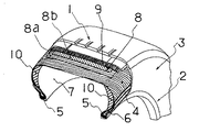
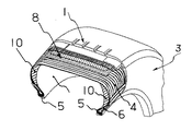
以下、本発明の実施の形態を図面を参照しながら詳細に説明する。図1は、本発明の空気入り安全タイヤの一例を示し、1はトレッド部、2はビード部、3はサイドウォール部である。左右のビード部2に連接してタイヤ径方向外側に左右のサイドウォール部3が延設され、この左右のサイドウォール部3間にタイヤ周方向に延在するトレッド部1が設けられている。タイヤ内側にはカーカス層4が1層配設されている。左右のビード部2にはタイヤラジアル方向断面形状が四角状に形成されたビードコア5がそれぞれ配置され、そのビードコア5の外周にはタイヤラジアル方向断面形状が三角状に形成されたビードフィラー6が設けられている。タイヤ最内層には、空気透過防止層を構成するインナーライナー層7が、タイヤ内側全面にわたって配設されている。
【0020】
トレッド部1のカーカス層外周側には、スチールコードからなる補強コードをタイヤ周方向に対して15度から30度で傾斜すると共に逆向きで互いに交差するように配列した、カーカス側ベルト層8aと踏面側ベルト層8bが埋設されている。このベルト層8の外周には、ベルト層8を保護するベルトカバー層9が積層されている。両サイドウォール部3には、カーカス層4とインナーライナー層7との間に、ランフラット性能を付与するためのタイヤラジアル方向断面形状が三日月状に形成されたサイド補強層10が設けられている。このサイド補強層10はサイドウォール部3の内側で、インナーライナー7の外側にタイヤ周方向に沿って、延設され環状に形成されている。
【0021】
本発明では、上述した構成の空気入り安全タイヤにおいて、カーカス層4の補強コードの方向を特定し、ベルト層の補強コードによって生ずるプライステアをカーカス層4によって生ずるプライステアで相殺することによって、例えタイヤのバックリング現象が大きくてもプライステアを抑制し、車両の片流れの原因となるプライステア成分が、著しく大きくならない構造になっているのである。
【0022】
サイド補強ゴム層は、サイドウォール部のたわみを抑制できる硬度(例えば、JIS A硬度70以上)を示すようなものであればいかなる配合でもよく、配合剤の種類や量も通常用いられる一般的なものを使用することが出来る。
【0023】
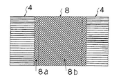
図2は図1のベルト層8とカーカス層4だけを抜き出し、平面に展開した部分展開図であって、ただ一層のカーカス層4がタイヤ外側から見て左下がりで、カーカス層の発生するプライステアは車両進行右向き、カーカス側ベルト層8aの補強コードの方向が左下がり、踏面側ベルト層8bの補強コードの方向が右下がりであり、ベルト層8が発生するプライステアは車両進行左向きである事を示し両者相殺している。
【0024】
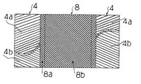
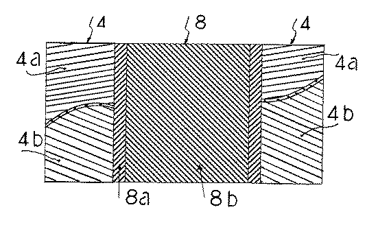
図3は他の本発明空気入り安全タイヤのベルト層8とカーカス層4の部分展開図であって、カーカス層が2層からなりタイヤ内面側のカーカス層4aの補強コードの方向がタイヤ外側から見て左下がり、ベルト層側カーカス層4bの補強コードの方向が右下がりで、カーカス層4が発生するプライステアは車両進行右向きである事を示している。カーカス側ベルト層8aの補強コードの方向が左下がり、踏面側ベルト層8bの補強コードの方向が右下がりであり、ベルト層8が発生するプライステアは車両進行左向きである事を示している。
【0025】
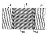
図4は他の本発明空気入り安全タイヤのベルト層8とカーカス層4の部分展開図であって、カーカス層が1層からなりタイヤ外側から見て右下がり、カーカス側ベルト層8aの補強コードの方向が右下がり、踏面側ベルト層8bの補強コードの方向が左下がりであり、ベルト層8が発生するプライステアは車両進行右向きである事を示している。
【0026】
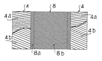
図5は他の本発明空気入り安全タイヤのベルト層8とカーカス層4の部分展開図であって、カーカス層が2層からなりタイヤ内面側のカーカス層4aの補強コードの方向がタイヤ外側から見て左下がり、ベルト層側カーカス層4bの補強コードの方向が右下がりで、しかも10度異なっている場合であって、カーカス側ベルト層8aの補強コードの方向が左下がりで、踏面側ベルト層8bの補強コードの方向が右下がりである事を示している。
【0027】
【実施例】
以下、実施例によって本発明を更に説明するが、本発明の範囲をこれらの実施例に限定するものでないことは言うまでもない。
【0028】
以下の各例に用いた試験タイヤは、次のように作製した。
【0029】
表1に示した配合組成(重量部)からなる、最大厚さ10mm、50%引っ張りモジュラス3.5MPa(JISK6251に準拠)からなる断面三日月形状のサイド補強層10を有するタイヤを図1および図2に示すように配置し、ベルト層をスチール2層としカーカス側ベルト層8aの補強コードの方向を左下がり20度、踏面側ベルト層8bの補強コードの方向を右下がり20度としたベルト補強層8を設置し本発明タイヤ(1)とした。タイヤサイズは245/45ZR17であって本発明タイヤ(1)と、他の本発明タイヤ(2)比較タイヤ(3)および従来タイヤ(4)をベルト層8とカーカス層4以外は同一に作製した。
【0030】
【表1】
【0031】
図2記載の本発明タイヤ(1)のカーカス層は1層で補強コードはポリエステルでタイヤ周方向に対する補強コードの角度は80度で左下がりである。
【0032】
図3記載の他の本発明タイヤ(2)のカーカス層は2層で補強コードはナイロンでタイヤ内面側カーカス層の補強コードのタイヤ周方向に対する角度は80度で左下がり、ベルト側カーカス層の補強コードのタイヤ周方向に対する角度は80度で右下がりで、対称に交差している。ベルト層8は本発明タイヤ(1)と同一である。
【0033】
図6記載の比較例タイヤ(3)のカーカス層は1層で補強コードはポリエステルでタイヤ周方向に対する補強コードの角度は本発明(1)と逆に80度で右下がりである。ベルト層8は本発明タイヤ(1)と同一である。
【0034】
図7および図8記載の従来タイヤ(4)のカーカス層はポリエステル1層で補強コードはラジアル方向である。ベルト層8は本発明タイヤ(1)と同一である。
【0035】
上記で得られた各タイヤを以下の試験に供し、その結果を下記表2に示した。結果は従来タイヤを100とした指数表示とし、数値が小さい方が良好である。
【0036】
(プライステア)
各タイヤを日本自動車タイヤ協会2002年版JATMAイヤーブックの標準リムを使用して、JASOC607に規定されたタイヤユニフォーミティー試験により各タイヤのプライステア量をもとめた。
【0037】
(ランフラット片流れ量試験)
各タイヤを日本自動車タイヤ協会2002年版JATMAイヤーブックの標準リムを使用して、最大負荷能力に対応する空気圧を充填し、前輪右側タイヤの空気を抜いた状態で、後輪駆動2000CCの車に装着して、平坦なコースをテストドライバーが舵を固定し80km/hの速度で50メートルずつ往復走行し、片流れの距離を測定した。従来例を100とする指数で表示し、この指数が小さいほどランフラット片流れ量が少なく優れていることを現す。
【0038】
【表2】
【0039】
【発明の効果】
トレッド部にバックリング現象を生じるような大きな張力がトレッド部に作用する場合であっても、ベルト層が発生するプライステア成分とカーカス層が発生するプライステア成分が逆むきであるため、両者が打ち消しあい結果としてプライステア量れを小さくすることが可能になり、車両の片流れを減少出来る。
【図面の簡単な説明】
【図1】本発明の空気入り安全タイヤの斜視部分断面展開図である。
【図2】本発明の空気入り安全タイヤのベルト層とカーカス層の部分展開図である。
【図3】他の本発明空気入り安全タイヤのベルト層とカーカス層の部分展開図である。
【図4】他の本発明空気入り安全タイヤのベルト層とカーカス層の部分展開図である。
【図5】他の本発明空気入り安全タイヤのベルト層とカーカス層の部分展開図である。
【図6】比較例の本発明空気入り安全タイヤのベルト層とカーカス層の部分展開図である。
【図7】従来の空気入りラジアル安全タイヤの空気入り安全タイヤの斜視部分断面展開図である。
【図8】従来の空気入りラジアル安全タイヤのベルト層とカーカス層の部分展開図である。
【図9】空気が抜けたタイヤのバックリング現象を示すタイヤ部分断面図である。
【符号の説明】
1 トレッド部
2 ビード部
3 サイドウォール部
4 カーカス層
4aタイヤ内面側のカーカス層
4bベルト層側カーカス層
5 ビードコア
6 ビードフィラー
7 インナーライナー層
8 ベルト層
8aカーカス側ベルト層
8b踏面側ベルト層
9 ベルトカバー層
10断面三日月形状のサイド補強層[0001]
TECHNICAL FIELD OF THE INVENTION
The present invention relates to a structure of a pneumatic safety tire, and more particularly, to a pneumatic safety tire in which a plysteer component is not significantly increased and a one-way flow of a vehicle is small even when the pneumatic safety tire is run in a state where air is deflated.
[0002]
[Prior art]
Conventionally, as a pneumatic safety tire having a run-flat property that allows the vehicle to run even after the air in the tire has been released due to a puncture or the like, as shown in FIG. There is a proposal of a tire having a crescent-shaped side reinforcing layer 10 made of high-hardness rubber between the carcass layer 4 and the inner liner layer 3. By arranging the side reinforcing layer 10 made of high-hardness rubber and having a crescent cross section as described above, the rigidity of the sidewall portion 3 is greatly increased, and the sidewall portion 3 is hardly bent even if air escapes ( For example, see Patent Document 1.)
[0003]
However, when the tire is run in a state where air is deflated, the cross-sectional shape of the tire becomes largely bent as shown in FIG. 9, the dynamic load radius of the tire is reduced, and the straightness of the vehicle is reduced. Even more unbearable is that when the air is evacuated, the crown center C portion of the tread rises, and the tire causes a so-called buckling phenomenon in which the vicinity of the tire shoulder S comes into contact with the ground. Becomes extremely large, causing a one-way flow of the vehicle (the vehicle is deflected to the right or to the left even if the steering wheel is kept straight ahead).
[0004]
That is, when the conventional pneumatic safety tire runs punctured due to injury or the like, a buckling phenomenon occurs in the tread portion 1 as shown in FIG. 9 and a large tension is applied to the tire inner surface side in the direction of F in FIG. work. The belt layer 8 on which the tension acts is composed of two or three layers of a composite material using a steel cord or the like as a reinforcing material. When a tension (or a compressive force) acts on the belt layer 8, an out-of-plane stress is generated. Due to the asymmetric laminated structure, ply steer occurs, and especially when the tire is run in a state where air is deflated, the ply steer component generated by the belt layer becomes excessive, which causes one-way flow of the vehicle. (For example, see Non-Patent Document 1.)
[0005]
[Patent Document 1]
JP-A-5-112110, FIG.
[0006]
[Non-patent document 1]
The Japan Society of Mechanical Engineers, "Advanced Composite Materials", Technical Technique Publishing Co., Ltd., May 25, 1990, pp. 147-152
[0007]
[Problems to be solved by the invention]
Accordingly, an object of the present invention is to provide a pneumatic safety tire in which the ply steer component is not significantly increased and the one-way flow of the vehicle is small even when the pneumatic safety tire is run in a state where air is deflated.
[0008]
[Means for Solving the Problems]
According to the present invention, there is provided a pneumatic safety tire in which a crescent-shaped cross-sectional side reinforcing layer for providing run flatness is provided between a carcass layer and an inner liner layer of a sidewall portion, wherein a belt layer is generated. There is provided a pneumatic safety tire in which a plysteer component generated and a plysteer component generated by a carcass layer are opposite to a vehicle traveling direction.
[0009]
By doing so, even when a large tension F that causes a buckling phenomenon on the tread portion acts on the tread portion 1, the plysteer component generated by the belt layer and the plysteer component generated by the carcass layer are not affected by the vehicle. Since they are opposite to each other in the traveling direction, they cancel each other, and as a result, it is possible to reduce the ply steer component of the entire tire and to reduce the one-sided flow of the vehicle. Here, the plysteer component is a value determined by a tire uniformity test specified in JASOC607.
[0010]
Further, according to the present invention, when the plysteer component in which the belt layer is generated is directed leftward in the vehicle traveling direction, the plysteer component in which the carcass layer is generated is directed rightward in the vehicle traveling direction, and the plysteer component in which the belt layer is generated is reduced. When the vehicle is traveling rightward in the vehicle traveling direction, a pneumatic safety tire is provided in which the ply steer component in which the carcass layer is generated is leftwardly traveling in the vehicle traveling direction.
[0011]
That is, in a country where vehicles travel on the right side, the direction of the reinforcing cord of the carcass-side belt layer 8a is set to the left as viewed from the outside of the tire in consideration of the road cant (mainly the inclination of the road surface for securing drainage). The direction of the reinforcing cord of the belt layer 8b on the tread side is lowered to the right, and the ply steer component generated by the belt layer is directed to the left in the vehicle traveling direction. In a country where vehicles travel on the left side, the reinforcing cord of the carcass side belt layer 8a is reversed. Is lowered to the right, the direction of the reinforcing cord of the belt layer 8b on the tread side is lowered to the left, and the ply steer component generated by the belt layer is directed to the right in the vehicle traveling direction. However, when the tire is run in a state where the air is deflated, the plysteer component generated by the belt layer becomes excessive. Therefore, by causing the plysteer component generated by the carcass layer to be generated in the opposite direction, when the tire is run in a state where air is deflated, the plysteer component generated as the whole tire is reduced, and the one-sided flow of the vehicle is reduced. It becomes possible.
[0012]
Further, according to the present invention, when the ply steer component generated by the two or three belt layers is directed to the left in the vehicle traveling direction, the direction of the reinforcing cord of the one carcass layer is the tire circumference when viewed from the outside of the tire. If the plysteer component generated by the belt layer is directed rightward in the vehicle traveling direction, the direction of the reinforcing cord of the one-layer carcass layer is the tire. Provided is a pneumatic safety tire that is inclined downward from more than 54.7 degrees to less than 90 degrees with respect to the tire circumferential direction when viewed from the outside.
[0013]
Note that the angle of the reinforcing cord described in this specification is an angle on the tire equator plane on the acute angle side with respect to the tire circumferential direction. In addition, the carcass layer may be provided with a radially extending carcass layer within a range that does not affect plysteer.
[0014]
This makes it possible to reverse the plysteer component generated by the belt layer and the plysteer component generated by the carcass layer. The components are in the same direction, making it impossible to reduce the one-sided flow. More preferably, the direction of the reinforcing cord of the carcass layer composed of one layer is preferably 70 to 85 degrees with respect to the tire circumferential direction when viewed from the outside of the tire, from the viewpoint of tire durability.
[0015]
According to the present invention, when the plysteer component in which the two or three belt layers are generated is directed leftward in the vehicle traveling direction, the direction of the reinforcement cord of the carcass layer on the belt side of the two carcass layers is the tire. If the plysteer component generated by the belt layer is directed rightward in the vehicle traveling direction, the carcass layer is composed of two layers. A pneumatic safety tire is provided in which the direction of the reinforcement cords of the carcass layer on the belt side is lower than the left side of more than 54.7 degrees to less than 90 degrees with respect to the tire circumferential direction when viewed from the outside of the tire.
[0016]
This makes it possible to reverse the plysteer component generated by the belt layer and the plysteer component generated by the carcass layer. When the tire runs in a state where the components are in the same direction and the air is deflated, it is impossible to reduce the ply steer component generated as the whole tire and to reduce the one-sided flow. More preferably, the direction of the reinforcing cord of the carcass layer on the belt side of the two-layer carcass layer is preferably 70 to 85 degrees with respect to the tire circumferential direction when viewed from the outside of the tire, from the viewpoint of tire durability. In addition, the carcass layer may be provided with a radially extending carcass layer within a range that does not affect plysteer.
[0017]
When the directions of the reinforcing cords of the two carcass layers are different from the tire circumferential direction at the tire inner surface side and the belt side, the directions of the reinforcing cords of the two carcass layers are at the tire inner surface side and the belt side. If it is opposite to the tire circumferential direction, it may be different within 20 degrees, but if it is more than 20 degrees, the durability performance particularly at the time of running at low internal pressure decreases, which is not preferable. In addition, the carcass layer may be provided with a radially extending carcass layer within a range that does not affect plysteer.
[0018]
Furthermore, the plysteer component generated by the carcass layer is that the angle of the reinforcing cord of the carcass layer on the belt side with respect to the tire circumferential direction is smaller than the angle of the reinforcing cord of the carcass layer on the inner surface side of the tire with respect to the tire circumferential direction by 5 degrees or more. Is more desirable. In addition, the carcass layer may be provided with a radially extending carcass layer within a range that does not affect plysteer.
[0019]
BEST MODE FOR CARRYING OUT THE INVENTION
Hereinafter, embodiments of the present invention will be described in detail with reference to the drawings. FIG. 1 shows an example of the pneumatic safety tire of the present invention, wherein 1 is a tread portion, 2 is a bead portion, and 3 is a sidewall portion. Left and right sidewall portions 3 are extended outwardly in the tire radial direction in connection with the left and right bead portions 2, and a tread portion 1 extending in the tire circumferential direction is provided between the left and right sidewall portions 3. One carcass layer 4 is provided inside the tire. A bead core 5 having a square cross section in the tire radial direction is disposed in each of the left and right bead portions 2, and a bead filler 6 having a triangular cross section in the tire radial direction is provided on the outer periphery of the bead core 5. Have been. As the innermost layer of the tire, an inner liner layer 7 constituting an air permeation preventing layer is provided over the entire inner surface of the tire.
[0020]
On the outer peripheral side of the carcass layer of the tread portion 1, a carcass-side belt layer 8a in which reinforcing cords made of steel cords are arranged so as to be inclined at 15 to 30 degrees with respect to the tire circumferential direction and intersect with each other in the opposite direction. The tread side belt layer 8b is buried. A belt cover layer 9 for protecting the belt layer 8 is laminated on the outer periphery of the belt layer 8. In both sidewall portions 3, between the carcass layer 4 and the inner liner layer 7, a side reinforcing layer 10 having a crescent shape in a tire radial cross section for providing run flat performance is provided. . The side reinforcing layer 10 extends in the tire circumferential direction inside the sidewall portion 3 and outside the inner liner 7 and is formed in an annular shape.
[0021]
In the present invention, for example, in the pneumatic safety tire having the above-described configuration, the direction of the reinforcing cord of the carcass layer 4 is specified, and the ply steer generated by the reinforcing cord of the belt layer is offset by the ply steer generated by the carcass layer 4. Even if the buckling phenomenon of the tire is large, ply steer is suppressed, and the ply steer component which causes one-sided flow of the vehicle is not significantly increased.
[0022]
The side reinforcing rubber layer may have any composition as long as it has a hardness (for example, JIS A hardness of 70 or more) capable of suppressing the deflection of the sidewall portion, and the type and amount of the compounding agent are generally used. Things can be used.
[0023]
FIG. 2 is a partial development view in which only the belt layer 8 and the carcass layer 4 of FIG. 1 are extracted and developed on a plane. Only one carcass layer 4 is lowered to the left as viewed from the outside of the tire, and the price at which the carcass layer is generated. The tear is directed to the vehicle traveling right, the direction of the reinforcing cord of the carcass side belt layer 8a is lowered to the left, the direction of the reinforcing cord of the tread side belt layer 8b is lowered to the right, and the ply steer generated by the belt layer 8 is directed to the vehicle traveling left. The facts are offset.
[0024]
FIG. 3 is a partial development view of the belt layer 8 and the carcass layer 4 of another pneumatic safety tire of the present invention, in which the carcass layer is composed of two layers and the direction of the reinforcing cord of the carcass layer 4a on the inner surface side of the tire is from the outside of the tire. When viewed downward, the direction of the reinforcing cords of the belt layer side carcass layer 4b is right downward, indicating that the ply steer in which the carcass layer 4 is generated is directed rightward in the vehicle traveling direction. The direction of the reinforcement cords of the carcass side belt layer 8a is lowered to the left, and the direction of the reinforcement cords of the tread side belt layer 8b is lowered to the right, indicating that the ply steer generated by the belt layer 8 is to the left in the vehicle traveling direction.
[0025]
FIG. 4 is a partial development view of the belt layer 8 and the carcass layer 4 of another pneumatic safety tire according to the present invention. Is downward to the right, the direction of the reinforcing cord of the tread-side belt layer 8b is downward to the left, indicating that the plysteer generated by the belt layer 8 is rightward in the vehicle traveling direction.
[0026]
FIG. 5 is a partial development view of the belt layer 8 and the carcass layer 4 of another pneumatic safety tire of the present invention, in which the carcass layer is composed of two layers and the direction of the reinforcing cord of the carcass layer 4a on the inner side of the tire is from the outside of the tire. When the direction of the reinforcing cords of the carcass side belt layer 8a is lower left and the direction of the reinforcing cords of the carcass side belt layer 8a is lower left, the direction of the reinforcing cord of the carcass side belt layer 8b is lower left. This indicates that the direction of the reinforcing cord of the layer 8b is downwardly rightward.
[0027]
【Example】
Hereinafter, the present invention will be further described with reference to Examples, but it goes without saying that the scope of the present invention is not limited to these Examples.
[0028]
Test tires used in each of the following examples were manufactured as follows.
[0029]
FIGS. 1 and 2 show tires having a crescent-shaped cross-section side reinforcing layer 10 having a maximum thickness of 10 mm and a 50% tensile modulus of 3.5 MPa (based on JIS K6251), having a composition shown in Table 1 (parts by weight). The belt reinforcing layer is arranged as shown in FIG. 2, the belt layer is made of two steel layers, the direction of the reinforcing cord of the carcass side belt layer 8a is lowered leftward by 20 degrees, and the direction of the reinforcing cord of the tread side belt layer 8b is lowered rightward by 20 degrees. 8 were set as tire (1) of the present invention. The tire size is 245 / 45ZR17, and the tire (1) of the present invention, the tire (2) of the present invention, the comparative tire (3), and the conventional tire (4) are manufactured identically except for the belt layer 8 and the carcass layer 4. .
[0030]
[Table 1]
[0031]
The carcass layer of the tire (1) of the present invention shown in FIG. 2 is one layer, the reinforcing cord is polyester, and the angle of the reinforcing cord with respect to the tire circumferential direction is 80 degrees and descends to the left.
[0032]
The carcass layer of the present invention tire (2) shown in FIG. 3 has two layers and the reinforcing cord is nylon, and the angle of the reinforcing cord of the carcass layer on the inner surface side of the tire with respect to the tire circumferential direction is lowered to the left by 80 degrees. The angle of the reinforcing cord with respect to the tire circumferential direction is 80 degrees, and it is sloping downward and crosses symmetrically. The belt layer 8 is the same as the tire (1) of the present invention.
[0033]
The carcass layer of the comparative example tire (3) shown in FIG. 6 is a single layer, the reinforcing cord is polyester, and the angle of the reinforcing cord with respect to the tire circumferential direction is 80 degrees downward to the right, contrary to the present invention (1). The belt layer 8 is the same as the tire (1) of the present invention.
[0034]
The carcass layer of the conventional tire (4) shown in FIGS. 7 and 8 has one layer of polyester and the reinforcing cord is in the radial direction. The belt layer 8 is the same as the tire (1) of the present invention.
[0035]
Each of the tires obtained above was subjected to the following tests, and the results are shown in Table 2 below. The result is expressed as an index with the conventional tire being 100, and the smaller the value, the better.
[0036]
(Price steer)
The ply steer amount of each tire was determined by a tire uniformity test specified in JASOC607 using a standard rim of the Japan Automobile Tire Association 2002 JATMA Yearbook.
[0037]
(Run flat single flow rate test)
Using the standard rims of the Japan Automobile Tire Association 2002 JATMA Yearbook, fill each tire with air pressure corresponding to the maximum load capacity, and deflate the right front tires. Then, the test driver fixed the rudder on a flat course and reciprocated 50 meters each at a speed of 80 km / h, and measured the distance of one-sided flow. The index is represented by an index with the conventional example being 100, and the smaller the index is, the smaller the flow rate of the run flat one is, and the more excellent it is.
[0038]
[Table 2]
[0039]
【The invention's effect】
Even when a large tension that causes a buckling phenomenon acts on the tread portion on the tread portion, the ply steer component generated by the belt layer and the ply steer component generated by the carcass layer are reversely peeled off, so that both are removed. As a result of the cancellation, the amount of plysteer can be reduced, and the one-sided flow of the vehicle can be reduced.
[Brief description of the drawings]
FIG. 1 is a perspective partial cross-sectional developed view of a pneumatic safety tire of the present invention.
FIG. 2 is a partially developed view of a belt layer and a carcass layer of the pneumatic safety tire of the present invention.
FIG. 3 is a partial development view of a belt layer and a carcass layer of another pneumatic safety tire of the present invention.
FIG. 4 is a partial developed view of a belt layer and a carcass layer of another pneumatic safety tire of the present invention.
FIG. 5 is a partially developed view of a belt layer and a carcass layer of another pneumatic safety tire of the present invention.
FIG. 6 is a partial development view of a belt layer and a carcass layer of a pneumatic safety tire of the present invention of a comparative example.
FIG. 7 is a perspective partial sectional development view of a pneumatic safety tire of a conventional pneumatic radial safety tire.
FIG. 8 is a partially developed view of a belt layer and a carcass layer of a conventional pneumatic radial safety tire.
FIG. 9 is a partial cross-sectional view of a tire showing a buckling phenomenon of a deflated tire.
[Explanation of symbols]
Reference Signs List 1 tread portion 2 bead portion 3 sidewall portion 4 carcass layer 4a carcass layer 4b on inner side of tire tire layer side carcass layer 5 bead core 6 bead filler 7 inner liner layer 8 belt layer 8a carcass side belt layer 8b tread side belt layer 9 belt Cover layer 10 crescent-shaped side reinforcement layer in cross section