JP2004206849A - Information recording medium, recorder, reproducing device, recording method, reproduction method - Google Patents
Information recording medium, recorder, reproducing device, recording method, reproduction method Download PDFInfo
- Publication number
- JP2004206849A JP2004206849A JP2003010406A JP2003010406A JP2004206849A JP 2004206849 A JP2004206849 A JP 2004206849A JP 2003010406 A JP2003010406 A JP 2003010406A JP 2003010406 A JP2003010406 A JP 2003010406A JP 2004206849 A JP2004206849 A JP 2004206849A
- Authority
- JP
- Japan
- Prior art keywords
- recording
- area
- information
- format
- recording layer
- Prior art date
- Legal status (The legal status is an assumption and is not a legal conclusion. Google has not performed a legal analysis and makes no representation as to the accuracy of the status listed.)
- Granted
Links
- 238000000034 method Methods 0.000 title claims description 42
- 230000003287 optical effect Effects 0.000 claims description 108
- 230000008569 process Effects 0.000 claims description 16
- 230000001678 irradiating effect Effects 0.000 claims description 6
- 239000010410 layer Substances 0.000 description 410
- 230000007547 defect Effects 0.000 description 42
- 238000012360 testing method Methods 0.000 description 38
- 239000000758 substrate Substances 0.000 description 35
- 239000011295 pitch Substances 0.000 description 23
- 238000010586 diagram Methods 0.000 description 22
- 230000002093 peripheral effect Effects 0.000 description 14
- 238000012545 processing Methods 0.000 description 12
- 230000008859 change Effects 0.000 description 9
- 230000000694 effects Effects 0.000 description 8
- 238000004519 manufacturing process Methods 0.000 description 6
- 239000004840 adhesive resin Substances 0.000 description 5
- 229920006223 adhesive resin Polymers 0.000 description 5
- 239000004417 polycarbonate Substances 0.000 description 5
- 239000002356 single layer Substances 0.000 description 5
- 239000012790 adhesive layer Substances 0.000 description 3
- 230000006378 damage Effects 0.000 description 3
- 238000012937 correction Methods 0.000 description 2
- 238000013461 design Methods 0.000 description 2
- 230000006866 deterioration Effects 0.000 description 2
- 238000006073 displacement reaction Methods 0.000 description 2
- 239000000428 dust Substances 0.000 description 2
- 229920005668 polycarbonate resin Polymers 0.000 description 2
- 239000004431 polycarbonate resin Substances 0.000 description 2
- 230000003252 repetitive effect Effects 0.000 description 2
- 238000002834 transmittance Methods 0.000 description 2
- 230000003321 amplification Effects 0.000 description 1
- 238000000149 argon plasma sintering Methods 0.000 description 1
- 230000005540 biological transmission Effects 0.000 description 1
- 230000015572 biosynthetic process Effects 0.000 description 1
- 230000015556 catabolic process Effects 0.000 description 1
- 238000005520 cutting process Methods 0.000 description 1
- 230000007423 decrease Effects 0.000 description 1
- 238000006731 degradation reaction Methods 0.000 description 1
- 238000001514 detection method Methods 0.000 description 1
- 239000002355 dual-layer Substances 0.000 description 1
- 238000000605 extraction Methods 0.000 description 1
- 230000010365 information processing Effects 0.000 description 1
- 230000002427 irreversible effect Effects 0.000 description 1
- 238000010030 laminating Methods 0.000 description 1
- 238000012986 modification Methods 0.000 description 1
- 230000004048 modification Effects 0.000 description 1
- 238000003199 nucleic acid amplification method Methods 0.000 description 1
- 238000004904 shortening Methods 0.000 description 1
- 230000001360 synchronised effect Effects 0.000 description 1
- 238000012546 transfer Methods 0.000 description 1
- 230000007704 transition Effects 0.000 description 1
Images


Classifications
-
- G—PHYSICS
- G11—INFORMATION STORAGE
- G11B—INFORMATION STORAGE BASED ON RELATIVE MOVEMENT BETWEEN RECORD CARRIER AND TRANSDUCER
- G11B7/00—Recording or reproducing by optical means, e.g. recording using a thermal beam of optical radiation by modifying optical properties or the physical structure, reproducing using an optical beam at lower power by sensing optical properties; Record carriers therefor
- G11B7/007—Arrangement of the information on the record carrier, e.g. form of tracks, actual track shape, e.g. wobbled, or cross-section, e.g. v-shaped; Sequential information structures, e.g. sectoring or header formats within a track
- G11B7/00736—Auxiliary data, e.g. lead-in, lead-out, Power Calibration Area [PCA], Burst Cutting Area [BCA], control information
-
- G—PHYSICS
- G11—INFORMATION STORAGE
- G11B—INFORMATION STORAGE BASED ON RELATIVE MOVEMENT BETWEEN RECORD CARRIER AND TRANSDUCER
- G11B20/00—Signal processing not specific to the method of recording or reproducing; Circuits therefor
- G11B20/10—Digital recording or reproducing
- G11B20/12—Formatting, e.g. arrangement of data block or words on the record carriers
- G11B20/1217—Formatting, e.g. arrangement of data block or words on the record carriers on discs
-
- G—PHYSICS
- G11—INFORMATION STORAGE
- G11B—INFORMATION STORAGE BASED ON RELATIVE MOVEMENT BETWEEN RECORD CARRIER AND TRANSDUCER
- G11B7/00—Recording or reproducing by optical means, e.g. recording using a thermal beam of optical radiation by modifying optical properties or the physical structure, reproducing using an optical beam at lower power by sensing optical properties; Record carriers therefor
- G11B7/004—Recording, reproducing or erasing methods; Read, write or erase circuits therefor
-
- G—PHYSICS
- G11—INFORMATION STORAGE
- G11B—INFORMATION STORAGE BASED ON RELATIVE MOVEMENT BETWEEN RECORD CARRIER AND TRANSDUCER
- G11B7/00—Recording or reproducing by optical means, e.g. recording using a thermal beam of optical radiation by modifying optical properties or the physical structure, reproducing using an optical beam at lower power by sensing optical properties; Record carriers therefor
- G11B7/12—Heads, e.g. forming of the optical beam spot or modulation of the optical beam
- G11B7/125—Optical beam sources therefor, e.g. laser control circuitry specially adapted for optical storage devices; Modulators, e.g. means for controlling the size or intensity of optical spots or optical traces
- G11B7/126—Circuits, methods or arrangements for laser control or stabilisation
- G11B7/1267—Power calibration
-
- G—PHYSICS
- G11—INFORMATION STORAGE
- G11B—INFORMATION STORAGE BASED ON RELATIVE MOVEMENT BETWEEN RECORD CARRIER AND TRANSDUCER
- G11B7/00—Recording or reproducing by optical means, e.g. recording using a thermal beam of optical radiation by modifying optical properties or the physical structure, reproducing using an optical beam at lower power by sensing optical properties; Record carriers therefor
- G11B7/24—Record carriers characterised by shape, structure or physical properties, or by the selection of the material
- G11B7/2403—Layers; Shape, structure or physical properties thereof
- G11B7/24035—Recording layers
- G11B7/24038—Multiple laminated recording layers
-
- G—PHYSICS
- G11—INFORMATION STORAGE
- G11B—INFORMATION STORAGE BASED ON RELATIVE MOVEMENT BETWEEN RECORD CARRIER AND TRANSDUCER
- G11B7/00—Recording or reproducing by optical means, e.g. recording using a thermal beam of optical radiation by modifying optical properties or the physical structure, reproducing using an optical beam at lower power by sensing optical properties; Record carriers therefor
- G11B7/24—Record carriers characterised by shape, structure or physical properties, or by the selection of the material
- G11B7/2407—Tracks or pits; Shape, structure or physical properties thereof
- G11B7/24073—Tracks
- G11B7/24079—Width or depth
-
- G—PHYSICS
- G11—INFORMATION STORAGE
- G11B—INFORMATION STORAGE BASED ON RELATIVE MOVEMENT BETWEEN RECORD CARRIER AND TRANSDUCER
- G11B7/00—Recording or reproducing by optical means, e.g. recording using a thermal beam of optical radiation by modifying optical properties or the physical structure, reproducing using an optical beam at lower power by sensing optical properties; Record carriers therefor
- G11B2007/0003—Recording, reproducing or erasing systems characterised by the structure or type of the carrier
- G11B2007/0009—Recording, reproducing or erasing systems characterised by the structure or type of the carrier for carriers having data stored in three dimensions, e.g. volume storage
- G11B2007/0013—Recording, reproducing or erasing systems characterised by the structure or type of the carrier for carriers having data stored in three dimensions, e.g. volume storage for carriers having multiple discrete layers
-
- G—PHYSICS
- G11—INFORMATION STORAGE
- G11B—INFORMATION STORAGE BASED ON RELATIVE MOVEMENT BETWEEN RECORD CARRIER AND TRANSDUCER
- G11B20/00—Signal processing not specific to the method of recording or reproducing; Circuits therefor
- G11B20/10—Digital recording or reproducing
- G11B20/12—Formatting, e.g. arrangement of data block or words on the record carriers
- G11B20/1217—Formatting, e.g. arrangement of data block or words on the record carriers on discs
- G11B2020/1218—Formatting, e.g. arrangement of data block or words on the record carriers on discs wherein the formatting concerns a specific area of the disc
- G11B2020/122—Burst cutting area [BCA]
-
- G—PHYSICS
- G11—INFORMATION STORAGE
- G11B—INFORMATION STORAGE BASED ON RELATIVE MOVEMENT BETWEEN RECORD CARRIER AND TRANSDUCER
- G11B20/00—Signal processing not specific to the method of recording or reproducing; Circuits therefor
- G11B20/10—Digital recording or reproducing
- G11B20/12—Formatting, e.g. arrangement of data block or words on the record carriers
- G11B20/1217—Formatting, e.g. arrangement of data block or words on the record carriers on discs
- G11B2020/1218—Formatting, e.g. arrangement of data block or words on the record carriers on discs wherein the formatting concerns a specific area of the disc
- G11B2020/1227—Formatting, e.g. arrangement of data block or words on the record carriers on discs wherein the formatting concerns a specific area of the disc one layer of multilayer disc
-
- G—PHYSICS
- G11—INFORMATION STORAGE
- G11B—INFORMATION STORAGE BASED ON RELATIVE MOVEMENT BETWEEN RECORD CARRIER AND TRANSDUCER
- G11B20/00—Signal processing not specific to the method of recording or reproducing; Circuits therefor
- G11B20/10—Digital recording or reproducing
- G11B20/12—Formatting, e.g. arrangement of data block or words on the record carriers
- G11B2020/1264—Formatting, e.g. arrangement of data block or words on the record carriers wherein the formatting concerns a specific kind of data
- G11B2020/1265—Control data, system data or management information, i.e. data used to access or process user data
- G11B2020/1275—Calibration data, e.g. specific training patterns for adjusting equalizer settings or other recording or playback parameters
-
- G—PHYSICS
- G11—INFORMATION STORAGE
- G11B—INFORMATION STORAGE BASED ON RELATIVE MOVEMENT BETWEEN RECORD CARRIER AND TRANSDUCER
- G11B2220/00—Record carriers by type
- G11B2220/20—Disc-shaped record carriers
- G11B2220/23—Disc-shaped record carriers characterised in that the disc has a specific layer structure
- G11B2220/235—Multilayer discs, i.e. multiple recording layers accessed from the same side
-
- G—PHYSICS
- G11—INFORMATION STORAGE
- G11B—INFORMATION STORAGE BASED ON RELATIVE MOVEMENT BETWEEN RECORD CARRIER AND TRANSDUCER
- G11B7/00—Recording or reproducing by optical means, e.g. recording using a thermal beam of optical radiation by modifying optical properties or the physical structure, reproducing using an optical beam at lower power by sensing optical properties; Record carriers therefor
- G11B7/24—Record carriers characterised by shape, structure or physical properties, or by the selection of the material
- G11B7/2407—Tracks or pits; Shape, structure or physical properties thereof
- G11B7/24073—Tracks
- G11B7/24082—Meandering
Landscapes
- Physics & Mathematics (AREA)
- Optics & Photonics (AREA)
- Engineering & Computer Science (AREA)
- Signal Processing (AREA)
- Optical Recording Or Reproduction (AREA)
- Optical Head (AREA)
- Optical Record Carriers And Manufacture Thereof (AREA)
- Signal Processing For Digital Recording And Reproducing (AREA)
Abstract
Description
【0001】
【発明の属する技術分野】
本発明は、少なくとも2層以上の記録層を備えた情報記録媒体、記録装置、再生装置、記録方法、再生方法に関する。
【0002】
【従来の技術】
近年、大量の情報の記録再生が可能なさまざまな情報記録媒体が開発されており、その中の一つに光ディスクがある。大容量の光ディスクの一つとして、2枚の光ディスクを張り合わせ、両面に対して記録再生できる両面光ディスクがある。しかしながら、ランダムアクセスを頻繁に要求する分野、例えばコンピュータ用記録媒体、ゲーム用記録媒体としては、光ディスクの記録容量が大きいことと同時に、裏返すことなく任意のデータにアクセスできることが望まれる。
【0003】
そこで1枚の光ディスクに大容量のデータを記録し、かつランダムアクセス可能な光ディスクとして、2層以上の記録層を備え、ディスクの片側の面から情報の再生が可能な多層光ディスクが考えられる。図7に片面に2層の記録層を備える光ディスク700の構成を示す。
【0004】
光ディスク700は、第1の記録層704と、第1の基板705と、接着樹脂703と、第2の基板701と、第2の記録層702とを備える。各基板にはクランプ穴706が形成されている。第2の記録層702は、ディスク情報領域707と、データ領域710とを備える。第1の記録層704は、ディスク情報領域711と、データ領域714とを備える。
【0005】
第1の基板705、第2の基板701は、ポリカーボネート樹脂等で形成し、第1の記録層704および第2の記録層702を保護する。再生専用領域であるディスク情報領域707には、第2の記録層702に照射するレーザ光のパワーを示す情報等が記録されている。再生専用領域であるディスク情報領域711には、第1の記録層704に照射するレーザ光のパワーを示す情報等が記録されている。
【0006】
【発明が解決しようとする課題】
光ディスク700では、例えば第1の記録層の再生後に、続けて第2の記録層の再生を行う際に、第1の記録層704に照射するレーザ光のパワーを示す情報を入手するためのディスク情報領域711の再生、データ領域714の再生、第2の記録層702に照射するレーザ光のパワーを示す情報を入手するためのディスク情報領域707の再生、データ領域710の再生という順の再生ステップが必要となる。もしくは、ディスク情報領域711の再生、ディスク情報領域707の再生、データ領域714の再生、データ領域710の再生という順の再生ステップを踏む必要がある。このように光ディスク700では、2つのディスク情報領域から情報を再生する必要があるため、レーザ光のパワーを示す情報のような光ディスク700のパラメータおよびフォーマットの再生ための所要時間が非常に長くなるという問題が生じる。
【0007】
本発明は上記問題点に鑑み、ディスク情報領域を再生する時間を短縮することを目的とする。
【0008】
【課題を解決するための手段】
本発明の情報記録媒体は、複数の記録層と、上記複数の記録層へのアクセスに関するパラメータおよび上記複数の記録層に関するフォーマットが格納されたディスク情報領域とを備え、上記ディスク情報領域は、上記複数の記録層のうちの1つである第1の記録層に配置されており、そのことにより上記目的が達成される。
【0009】
上記第1の記録層にはアドレスが割り当てられており、上記パラメータは、上記第1の記録層に照射するレーザ光のパワーの値を示す第1の照射パワー情報と、上記複数の記録層のうちの他の記録層に照射するレーザ光のパワーの値を示す第2の照射パワー情報とを含み、上記ディスク情報領域のうちの上記第1の照射パワー情報が格納された領域に割り当てられているアドレスは、上記ディスク情報領域のうちの上記第2の照射パワー情報が格納された領域に割り当てられているアドレスよりも小さくてもよい。
【0010】
上記ディスク情報領域と同じ情報を格納するさらなるディスク情報領域をさらに備え、上記さらなるディスク情報領域は、上記複数の記録層のうちの他の1つである第2の記録層に配置されていてもよい。
【0011】
上記第1の記録層は、上記複数の記録層のうち基準層として予め決められた記録層であってもよい。
【0012】
上記複数の記録層は情報の書き込みが可能な記録層であり、上記情報記録媒体は、レーザ光の記録パワーを調整するための複数の調整領域をさらに備え、上記複数の記録層のそれぞれは、上記複数の調整領域のうち対応する1つを備えてもよい。
【0013】
上記複数の記録層のうちの1つである第2の記録層はバッファ領域を備え、上記バッファ領域は、上記複数の調整領域のうちの上記第2の記録層が備える調整領域に隣接して配置されてもよい。
【0014】
上記複数の調整領域のそれぞれは、上記情報記録媒体の異なる半径位置に配置されてもよい。
【0015】
上記情報記録媒体は追記型情報記録媒体であってもよい。
【0016】
上記第1の記録層にはアドレスが割り当てられており、上記パラメータは、上記第1の記録層へのアクセスに関する第1パラメータと、上記複数の記録層のうちの他の記録層へのアクセスに関する第2パラメータとを含み、上記ディスク情報領域のうちの上記第1パラメータが格納された領域に割り当てられているアドレスは、上記ディスク情報領域のうちの上記第2パラメータが格納された領域に割り当てられているアドレスよりも小さくてもよい。
【0017】
上記第1の記録層にはアドレスが割り当てられており、上記フォーマットは、上記第1の記録層に関する第1フォーマットと、上記複数の記録層のうちの他の記録層に関する第2フォーマットとを含み、上記ディスク情報領域のうちの上記第1フォーマットが格納された領域に割り当てられているアドレスは、上記ディスク情報領域のうちの上記第2フォーマットが格納された領域に割り当てられているアドレスよりも小さくてもよい。
【0018】
上記複数の記録層に形成されたユーザデータを記録するためのデータ領域をさらに備え、上記複数の記録層には溝が形成されており、上記複数の記録層のうちの1つである第2の記録層は、上記第2の記録層の一部である上記ディスク情報領域と同じ半径位置の領域と、上記第2の記録層の他の一部である上記データ領域の一部が配置された領域とを備え、上記ディスク情報領域と同じ半径位置の領域に形成された溝の形状の形式と、上記データ領域の一部が配置された領域に形成された溝の形状の形式とが同じであってもよい。
【0019】
上記複数の記録層の少なくとも一部には溝が形成されており、上記複数の記録層のうちの1つである第2の記録層は、上記第2の記録層の一部である上記ディスク情報領域と同じ半径位置の領域に溝を有さなくてもよい。
【0020】
上記複数の記録層には溝が形成されており、上記複数の記録層のうちの1つである第2の記録層が有する溝の形状の形式は一定であってもよい。
【0021】
上記第1の記録層には溝が形成されており、上記ディスク情報領域の溝の形状の形式と、上記第1の記録層の一部である上記ディスク情報領域と隣接する領域の溝の形状の形式とが異なってもよい。
【0022】
上記第1の記録層には溝が形成されており、上記ディスク情報領域の溝と、上記第1の記録層の一部である上記ディスク情報領域と隣接する領域の溝とは連続していてもよい。
【0023】
上記パラメータおよび上記フォーマットは、上記第1の記録層に関する第1のパラメータおよび第1のフォーマットを含み、上記パラメータおよび上記フォーマットは、上記複数の記録層のうちの他の1つである第2の記録層に関する第2のパラメータおよび第2のフォーマットを含み、上記ディスク情報領域のうちの上記第1のパラメータおよび上記第1のフォーマットが格納された領域の長さと、上記ディスク情報領域のうちの上記第2のパラメータおよび上記第2のフォーマットが格納された領域の長さとが同じであってもよい。
【0024】
上記パラメータは、上記第1の記録層へのアクセスに関する第1パラメータを含み、上記フォーマットは、上記第1の記録層に関する第1フォーマットを含み、上記ディスク情報領域には上記第1パラメータと上記第1フォーマットとの組が連続して繰り返し格納されていてもよい。
【0025】
上記パラメータは、上記複数の記録層のうちの他の1つである第2の記録層へのアクセスに関する第2パラメータを含み、上記フォーマットは、上記第2の記録層に関する第2フォーマットを含み、上記ディスク情報領域には上記第2パラメータと上記第2フォーマットとの組が連続して繰り返し格納されていてもよい。
【0026】
上記ディスク情報領域は、上記パラメータと上記フォーマットとの組を複数個格納していてもよい。
【0027】
ダミー領域をさらに備え、上記複数の組は第1の組と第2の組とを含み、上記ダミー領域は、上記ディスク情報領域の一部である上記第1の組が配置された領域と上記ディスク領域の他の一部である上記第2の組が配置された領域との間に配置されていてもよい。
【0028】
上記ダミー領域の長さは、上記パラメータと上記フォーマットとの組が格納された領域の長さの整数倍であってもよい。
【0029】
上記第1の記録層にはアドレスが割り当てられており、上記パラメータは、上記第1の記録層へのアクセスに関する第1のパラメータと、上記複数の記録層のうちの他の記録層へのアクセスに関する第2のパラメータとを含み、上記第1のパラメータと上記第2のパラメータとは、上記ディスク情報領域のうちの同じアドレスが割り当てられた領域に格納されていてもよい。
【0030】
上記第1の記録層にはアドレスが割り当てられており、上記フォーマットは、上記第1の記録層に関する第1のフォーマットと、上記複数の記録層のうちの他の記録層に関する第2のフォーマットとを含み、上記第1のフォーマットと上記第2のフォーマットとは、上記ディスク情報領域のうちの同じアドレスが割り当てられた領域に格納されていてもよい。
【0031】
本発明の情報記録媒体に情報を記録するための記録装置において、上記情報記録媒体は、複数の記録層と、上記複数の記録層へのアクセスに関するパラメータおよび上記複数の記録層に関するフォーマットが格納されたディスク情報領域とを備え、上記ディスク情報領域は、上記複数の記録層のうちの1つである第1の記録層に配置されており、上記記録装置は、上記情報記録媒体に上記情報を光学的に書き込むことが可能な光ヘッド部と、上記光ヘッド部を用いた記録処理の実行を制御する制御部とを備え、上記記録処理は、上記ディスク情報領域に格納された上記パラメータおよび上記フォーマットを再生するステップと、上記再生されたパラメータおよびフォーマットに基づいて、上記情報記録媒体に上記情報を記録するステップとを包含し、そのことにより上記目的が達成される。
【0032】
本発明の情報記録媒体に記録された情報を再生するための再生装置において、上記情報記録媒体は、複数の記録層と、上記複数の記録層へのアクセスに関するパラメータおよび上記複数の記録層に関するフォーマットが格納されたディスク情報領域とを備え、上記ディスク情報領域は、上記複数の記録層のうちの1つである第1の記録層に配置されており、上記再生装置は、上記情報記録媒体に記録された上記情報を光学的に読み出すことが可能な光ヘッド部と、上記光ヘッド部を用いた再生処理の実行を制御する制御部とを備え、上記再生処理は、上記ディスク情報領域に格納された上記パラメータおよび上記フォーマットを再生するステップと、上記再生されたパラメータおよびフォーマットに基づいて、上記情報記録媒体に記録された上記情報を再生するステップとを包含し、そのことにより上記目的が達成される。
【0033】
本発明の情報記録媒体に情報を記録するための記録方法において、上記情報記録媒体は、複数の記録層と、上記複数の記録層へのアクセスに関するパラメータおよび上記複数の記録層に関するフォーマットが格納されたディスク情報領域とを備え、上記ディスク情報領域は、上記複数の記録層のうちの1つである第1の記録層に配置されており、上記記録方法は、上記ディスク情報領域に格納された上記パラメータおよび上記フォーマットを再生するステップと、上記再生されたパラメータおよびフォーマットに基づいて、上記情報記録媒体に上記情報を記録するステップとを包含し、そのことにより上記目的が達成される。
【0034】
本発明の情報記録媒体に記録された情報を再生するための再生方法において、上記情報記録媒体は、複数の記録層と、上記複数の記録層へのアクセスに関するパラメータおよび上記複数の記録層に関するフォーマットが格納されたディスク情報領域とを備え、上記ディスク情報領域は、上記複数の記録層のうちの1つである第1の記録層に配置されており、上記再生方法は、上記ディスク情報領域に格納された上記パラメータおよび上記フォーマットを再生するステップと、上記再生されたパラメータおよびフォーマットに基づいて、上記情報記録媒体に記録された上記情報を再生するステップとを包含し、そのことにより上記目的が達成される。
【0035】
【発明の実施の形態】
以下、本発明の実施の形態における光ディスクについて、図面を参照して説明する。
【0036】
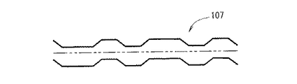
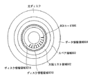
図1は本発明の実施の形態における2層の記録層を備えた書き換え型光ディスク100を示す。
【0037】
光ディスク100は、第1の記録層104と、第1の基板105と、接着樹脂103と、第2の基板101と、第2の記録層102とを備える。各基板および各記録層にはクランプ穴106が形成されている。光ディスク100は、ユーザデータを記録するためのデータ領域115を備える。データ領域115は第1の記録層104と第2の記録層102との両方に渡って配置されている。データ領域115の一部であるデータ領域110が第2の記録層102に配置されており、データ領域115の一部であるデータ領域114が第1の記録層104に配置されている。
【0038】
第2の記録層102は、ディスク情報領域107と、欠陥リスト領域108と、スペア領域109と、データ領域110とを備える。第1の記録層104は、ディスク情報領域111と、欠陥リスト領域112と、スペア領域113と、データ領域114とを備える。第1の記録層104と第2の記録層102とは、光ディスク100の片面に設けられている。
【0039】
ディスク情報領域107、欠陥リスト領域108、スペア領域109、データ領域110、ディスク情報領域111、欠陥領域112、スペア領域113、データ領域114には、スパイラル状もしくは同心円状に複数のトラックが形成されている。トラックは複数のセクタを備える。
【0040】
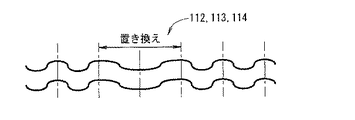
ここで欠陥リスト領域108、スペア領域109、データ領域110、欠陥リスト領域112、スペア領域113、データ領域114は記録可能な領域であり、トラックは所定の周期で蛇行している。図2Bに示すトラックのように部分的な高調波成分の重畳によりトラックにアドレス情報等が記録されている。また、図2Cに示すトラックのように所定の周期の整数倍の区間を部分的に異なる周波数で置き換えることにより、トラックにアドレス情報等が記録されていてもよい。また図2Dに示すトラックのようにトラックの所定の周期の整数倍の区間を、部分的に異なる変調パターンもしくは異なる複数の周波数の組み合わせで置き換えても良い。トラックの形状の形式を図2Cや図2Dに示す形式のようにすることで、所定周期部分における位相の連続性を確保することができ、クロック抽出処理が容易になる。
【0041】
第1の基板105、第2の基板101は、ポリカーボネート樹脂等で形成されており、第1の記録層104および第2の記録層102を保護する。ディスク情報領域107は再生専用領域であり、第1の記録層104および第2の記録層102へのアクセスに関するパラメータ、および第1の記録層104および第2の記録層102に関するフォーマットが格納されている。ディスク情報領域111も再生専用領域であり、第1の記録層104および第2の記録層102へのアクセスに関するパラメータ、および第1の記録層104および第2の記録層102に関するフォーマットが格納されている。ディスク情報領域111にはディスク情報領域107に記録された情報と同じ情報が記録されている。光ディスク100は、ディスク情報領域107およびディスク情報領域111の両方を備えても良いし、ディスク情報領域107およびディスク情報領域111のいずれか一方のみを備えても良い。ディスク情報領域107は、パラメータとして第2の記録層102に対する情報の記録再生時に第2の記録層102に照射する適切なレーザ光の照射パワーを示す第2の照射パワー情報と、第1の記録層104に対する情報の記録再生時に第1の記録層104に照射する適切なレーザ光の照射パワーを示す第1の照射パワー情報とを格納する。ディスク情報領域111も、パラメータとして第2の記録層102に対する情報の記録再生時に第2の記録層102に照射する適切なレーザ光の照射パワーを示す第2の照射パワー情報と、第1の記録層104に対する情報の記録再生時に第1の記録層104に照射する適切なレーザ光の照射パワーを示す第1の照射パワー情報とを格納する。上記情報の記録は、トラックを基本周期または倍周期毎に径方向に変調させることにより行う。トラック変調の一例を図2Aに示す。
【0042】
本実施の形態のように、ディスク情報領域107、ディスク情報領域111のような再生専用領域の溝の形状の形式と、欠陥リスト領域108、スペア領域109、データ領域110、欠陥領域112、スペア領域113、データ領域114のような記録可能領域の溝の形状の形式とを異ならせることにより、光ディスク装置がトラックに記録されたアドレスを再生する前に、記録再生装置は今再生している領域がディスク情報領域であるかどうかを認識することができる。
【0043】
多層ディスクにおいて、特に読み出しを行う側のディスク表面から最も遠い層を再生する際のレーザ光の照射パワーは、単層ディスクを再生する際のレーザ光の照射パワーよりも大きいことが予想される。そのため光ディスク100を光ディスク装置に装着したときに、単層ディスクを再生する際のレーザ光の照射パワーにより再生したために、照射パワーが不足してアドレスが再生できない場合でも、溝の形状から得られるトラッキング信号波形からディスク情報領域であるかどうかを判定することができる。
【0044】
図3は、本発明の実施の形態における記録再生装置300を示す。記録再生装置300は、スピンドルモータ302と、光ヘッド303と、レーザ光制御回路304と、サーボ回路305と、再生二値化回路306と、ディジタル信号処理回路307と、記録補償回路308と、CPU309とを備える。
【0045】
記録再生装置300には光ディスク100(図1)が搭載される。記録再生装置300はホストPC310と情報の送受信を行う。
【0046】
制御部として機能するCPU309は、内蔵された制御プログラムに従って、記録再生装置300の全体動作を制御する。以下に説明するように、光ヘッド303は、光ディスク100の片側から、光ディスク100に情報を光学的に書き込むことが可能である。また、光ヘッド303は、光ディスク100から情報を光学的に読み出すことが可能である。CPU309は、光ヘッド303を用いて記録処理の実行および再生処理の実行を制御する。記録処理は、ディスク情報領域に格納されたパラメータおよびフォーマットを再生するステップと、再生されたパラメータおよびフォーマットに基づいて光ディスク100にユーザデータを記録するステップとを含む。再生処理は、ディスク情報領域に格納されたパラメータおよびフォーマットを再生するステップと、再生されたパラメータおよびフォーマットに基づいて光ディスク100に記録されたユーザデータを再生するステップとを含む。以下に記録再生装置300の動作についてより詳細に説明する。
【0047】
光ディスク100については図1を参照して説明したとおりである。スピンドルモータ302は、光ディスク100を回転させるためのモータである。光ヘッド303は、レーザ光を光ディスク100に照射する。また、レーザ光311を光ディスク100に照射した結果の反射光を電気的な信号に変換して再生信号として出力する。レーザ光制御回路304は、光ヘッド303から出力されるレーザ光のパワーを制御する。これらの制御はCPU309の指示に基づいて行う。サーボ回路305は、光ヘッド303の位置制御、フォーカス、トラッキングの制御、スピンドルモータ302の回転制御を行う。再生二値化回路306は、光ヘッド303より得られた再生信号(データ情報は和信号、ディスク情報領域やアドレスに関する情報は差信号)に、増幅処理、二値化処理を行い、二値化信号を生成する。また内部されたPLL(図示せず)により、二値化信号に同期したクロックが生成される。
【0048】
ディジタル信号処理回路307は、二値化信号に所定の復調処理やエラー訂正処理を行う。データ記録時は記録データにエラー訂正コード付加処理、所定の変調処理を行い、変調データを生成する。記録補償回路308は、変調データをパルス列から構成される光変調データに変換し、さらに光変調データのパルス幅等を、ディスク情報領域の再生信号や、予めCPU309に記憶されているデータを基に微妙に調整し、ピット形成に適した記録パルス信号に変換する。CPU309は、記録再生装置300全体の制御を行う。ホストPC310は、コンピュータ(図示せず)、アプリケーション(図示せず)、オペレーティングシステム(図示せず)等を備え、記録再生装置300に情報の記録や再生の要求を行う。
【0049】
光ディスク100が記録再生装置300に挿入されると、レーザ光制御回路304、サーボ回路305からの信号に基づいて、光ヘッド303は所定の照射パワーによりディスク情報領域111を再生し、第1の記録層および第2の記録層に情報(ユーザデータ)を記録する際の照射パワー情報等を再生する。ホストPC310からの記録要求があると、CPU309はレーザ光制御回路304に第1の記録層104に記録を行う際の記録パワーを設定し、光ヘッド303を用いてデータ領域114に情報の記録を行う。続いてレーザ光制御回路304に第2の記録層102に記録を行う際の記録パワーを設定し、データ領域110に情報の記録を行う。
【0050】
光ディスク100のディスク情報領域111に、第1の記録層104および第2の記録層102の両方のパラメータおよびフォーマット(記録する際の照射パワー情報等)が記録されていることにより、ディスク情報領域から情報を再生する回数が1回ですむ。これにより、第2の記録層102に記録するためにディスク情報領域107を再生し、第1の記録層104に記録するためにディスク情報領域111を再生する場合と比較して、ディスク情報領域へのアクセスに必要な時間を短縮することができる。
【0051】
また本実施の形態のように、ディスク情報領域107とディスク情報領域111の両方にパラメータおよびフォーマットが記録されていることにより、どちらの層を再生しても両方の層に記録を行う際の照射パワー情報等を入手することができる。このため、接着樹脂103の厚みむらやサーボ回路305によるフォーカス制御時の外乱により、所定の記録層とは異なる層の情報を再生してしまった場合でも、その層のディスク情報領域の情報を再生することにより記録に必要な情報を入手することができる。
【0052】
さらに本実施の形態のように、ディスク情報領域107とディスク情報領域111の両方に照射パワー情報等が記録されていることにより、例えばデータ領域114に最初に記録する際にはディスク情報領域111を再生し、データ領域110に最初に記録する際にはディスク情報領域107を再生することにより、データを記録するまでの所要時間を短縮することができる。
【0053】
なお本実施の形態では、第1の記録層104および第2の記録層102の二つの層に記録を行うとしているが記録可能な記録層は3つ以上でも良い。また本実施の形態では、ディスク情報領域107、ディスク情報領域111への情報の記録フォーマットとして、トラックの蛇行を基本周期および倍周期毎に径方向に変調させているが、図2Bに示すように、所定の周期で蛇行したトラックへの部分的な高調波成分の重畳により情報を記録したり、図2Cや図2Dに示すように、所定の周期で蛇行したトラックの一部を異なる周波数やパターンに置き換えることによって情報を記録しても良い。特に全ての領域で溝形状の形式を等しくすることで基板をより簡単に製造することができる。
【0054】
また本実施の形態では、ディスク情報領域107、ディスク情報領域111は共にスパイラル状もしくは同心円状に複数のトラックを有するとしている。ディスク情報領域107、ディスク情報領域111は、凹凸ピットにより情報が記録されていても良いし、出荷前等に、データ領域に記録を行う方法と同じ方法でディスク情報領域にプリ記録がなされていても良い。
【0055】
またディスク情報領域107、ディスク情報領域111のトラックピッチ(もしくは径方向のピットピッチ)が、欠陥リスト領域108、スペア領域109、データ領域110、欠陥リスト領域112、スペア領域113、データ領域114のトラックピッチ(もしくは径方向のピットピッチ)と異なっていても良い。ディスク情報領域のトラックピッチを広げることで隣接トラックからの影響をより低減することができる。
【0056】
またディスク情報領域のトラックピッチやピットピッチをデータ領域等の記録可能な領域のトラックピッチやピットピッチより広げることで、例えばレーザ波長の長い光ヘッドを有する光ディスク装置においてもディスク情報領域を再生することが可能となり、最低限の情報をユーザに返すことができる。すなわちディスク情報領域についての異機種間の互換性を広げることで、例え仕様上記録ができない場合でも、記録ができない理由を明確にすることができる。
【0057】
ところで一般に一方の層から他方の層への垂直方向のレーザ光のスポットの移動においては、基板の貼り合わせのずれや、各基板のクランプ穴の位置ずれ等により同一半径位置に移動することは難しい。例えば第1の記録層104の内周側から1000トラック目の位置から、第2の記録層102の内周側から1000トラック目の位置に移動しようとしても、±50トラック程度のずれが生じる。従って再生専用のトラックと記録可能なトラックの境界付近で層間をレーザ光のスポットが移動する際に、移動先の層においてトラックが不連続であると不安定な動作となり、速やかに移動先の層での再生や記録ができなくなる。
【0058】
そこでディスク情報領域107、ディスク情報領域111のトラックピッチが欠陥リスト領域108、スペア領域109、データ領域110、欠陥リスト領域112、スペア領域113、データ領域114のトラックピッチと異なっている場合でも、ディスク情報領域107のトラックの溝は、ディスク情報領域107と隣接する領域(図1に示す例では欠陥リスト領域108である。スペア領域109、データ領域110であってもよい)のトラックの溝と連続して繋がっていることが望ましい。同様にディスク情報領域111のトラックの溝は、ディスク情報領域111と隣接する領域(図1に示す例では欠陥リスト領域112である。スペア領域113、データ領域114であってもよい)のトラックの溝と連続して繋がっていることが望ましい。なおトラックピッチの変移はデータ容量の観点から100トラック程度以内で完了することが望ましいが、ピッチ変動についてはできるだけ緩やかに変動することが望ましい。またレーザ光のスポットが層間を移動する際にどの層のトラックに移動しても速やかに再生できるよう、サーボの観点からはディスク情報領域のトラックピッチと、欠陥リスト領域やスペア領域やデータ領域のトラックピッチとの差は望ましくは10%程度であり、最大でも15%以下であることが望ましい。
【0059】
なお本実施の形態では、ディスク情報領域では図2Aに示すようにトラックに対して基本周期および倍周期で径方向に変調させることによりディスク情報を記録する。欠陥リスト領域、スペア領域、データ領域では図2Bや図2Cや図2Dに示すように、所定の周期で蛇行するトラックへの部分的な周波数変調や、高調波成分の重畳によりアドレス情報等が記録されている。トラックピッチの変移領域の全部もしくは一部においては、ディスク情報領域、欠陥リスト領域、スペア領域、データ領域のどの領域にもない変調方式でトラックが形成されていても良いし、逆に全く変調されていなくても良いし、さらには蛇行していなくとも良い。
【0060】
このように、トラックピッチの変移領域において、その前後の領域と変調方式や形状の形式を異ならせることにより、変移領域であることを記録再生装置300に速やかに認識することができる。
【0061】
以上のようにトラックピッチが異なる領域間において不連続箇所をなくすことにより、不連続箇所がある光ディスクにおいてレーザ光のスポットが不連続箇所の移動元から半径方向に大きく離れてから移動先へ移動する場合と比較して、移動先の領域での処理を速やかに開始することができる。
【0062】
また本実施の形態ではディスク情報領域はディスクの最内周側に設けられているが、最外周側に設けられていても良く、さらに最内周側と最外周側の両方に設けられていても良い。
【0063】
なお本実施の形態では、ディスク情報領域107とディスク情報領域111の両方に第1の記録層および第2の記録層に記録する際の照射パワー情報等が記録されているが、再生する層が特定できる場合には全ての層のディスク情報領域に全ての層の照射パワー情報等が記録されていなくても良い。
【0064】
1層の記録層を備えた光ディスクの読み出しを行う側のディスク表面から記録層までの距離と、光ディスク100の読み出しを行う側のディスク表面からの距離がほぼ同じ記録層を基準層とし、少なくとも基準層はディスク情報領域を有するようにしてもよい。このことにより、1層の記録層を備えた光ディスクに記録再生を行う記録再生装置を用いて、光ディスク100の任意の層のディスク情報を入手することができ、記録再生装置の構成を簡単にすることができる。基準層となる記録層(例えば第1の記録層104)は、複数の記録層の中から予め決められている。
【0065】
なおディスク表面からの距離が遠いほど、チルトによる再生信号の劣化が大きくなる。このことから、ディスク表面からの距離が1層の記録層を備えたディスクとほぼ同じ層である基準層をディスク表面から最も遠い層にすることが望ましい。その際に、基準層以外の記録層の一部の領域であって基準層のディスク情報領域と同じ半径位置の領域の溝の形状の形式を、ユーザデータを記録するためのデータ領域の溝の形状の形式と同じすることにより、半径位置に関わらず透過率を同じにすることができる。これにより、基準層のディスク情報領域を再生するための特別な検出手段を必要とせず、記録再生装置の構成を簡単にすることができ、さらに記録層の製造が容易になる。
【0066】
特に、複数の記録層を備えた多層ディスクにおいて、基準層以外の記録層の溝形状の形式をデータ領域と同じ溝形状の形式としての溝形状の形式を一つにすることにより基板の製造が非常に容易になる。
【0067】
また基準層にディスク情報領域を設ける場合に、基準層以外の記録層の一部の領域であって基準層のディスク情報領域と同じ半径位置の領域を溝を有しない平らな構造にすることにより、基準層以外の記録層の光の散乱を低減することができ、基準層の再生信号品質を向上させることができる。
【0068】
また基準層にのみディスク情報領域を設けることで、光ディスクのディスク情報領域が配置された半径位置付近を再生することにより、再生している記録層が基準層かどうかを簡単に判定することができる。
【0069】
ディスク情報領域は、複数の記録層に関するパラメータとして、再生する際の推奨照射パワー情報、記録する際の推奨照射パワー情報、最大照射パワー情報、記録時のパルス幅、記録時に複数の照射パワーを組み合わせる場合のそれらの比率、記録する際の最適な照射パワーを決定する際に利用するマージン定数等を格納し得る。
【0070】
ディスク情報領域は、複数の記録層に関するフォーマットとして、ディスク名称、ディスクサイズ、バージョン情報、任意の層のディスクタイプ(すなわち記録再生可能な層か、再生専用の層かを示す識別子)、記録可能な層の総数、再生専用の層の総数、全部の層の総数を格納し得る。さらにディスク情報領域は、複数の記録層に関するフォーマットとして、任意の層の情報のコピー可否を示す識別子、クロック情報、ディスク製造後に固有情報を付与するためのBCA(Burst Cutting Area)が配置されているかどうかを示す識別子、転送レート、記録再生方向、物理アドレス開始番号、物理アドレス終了番号、論理アドレス開始番号、論理アドレス終了番号、最短マーク長、記録速度等を格納し得る。
【0071】
なお各記録層毎に記録再生に必要なパラメータを設定することによりディスク設計における自由度を高めることができる。例えば高密度の記録を実現するに当たり、複数の記録層に情報の記録を行う場合には、少なくとも光が通過する他層についてはその反射のばらつきを考慮する必要がある。このため一つの記録層にのみ記録を行う場合に比べてより精度の高い設計が要求される。その際に、例えば第1の記録層104も第2の記録層102も同じ照射パワーで再生しなければならないとすると、記録膜の観点からは設計が困難になることが予想される。例えば第2の記録層102は高透過率の下で記録性能を確保しなければならない。そこで再生時の照射パワーの限定は行わず、その代わりに照射パワー情報をディスク情報領域に記録しておくことにより、第1の記録層104を再生する際の照射パワーを高くすることが可能となり、第2の記録層102の記録膜設計における自由度を高めることができる。
【0072】
さらに任意の層の記録再生に必要なパラメータを少なくとも一つの記録層のディスク情報領域にまとめて記録しておくことにより、ディスク全体の最適な制御方法を直ちに把握することができる。
【0073】
なおBCAはディスク情報領域の内容が同一のディスクについて、さらに詳細にディスクの分類を行うものであり、ディスクの製造後に工場においてバーコード状の記録を行う。BCAの配置は少なくとも一層、望ましくは基準層に行われていれば良い。このときBCAの存在しない層において、基準層と溝形状を異ならせることにより、基準層においてBCAが配置されている半径範囲を再生することにより基準層かどうかを簡単に判定することができる。特に基準層以外の記録層において、BCAが配置されている半径範囲を、溝を有しない平らな構造にすることにより、他層における光の散乱を低減することができ、BCAの再生信号品質を向上させることができるとともに基板の製造を容易にする。
【0074】
なおBCAの情報の記録は、記録可能な領域に記録するよりもはるかに大きい出力でレーザ照射を行うため、欠陥リスト領域や、スペア領域やデータ領域等の記録可能な領域の記録膜の特性にダメージを与える危険性がある。このことから、記録位置ばらつきを含めて記録可能な領域にはBCAが配置されないようにすることが望ましい。仮に記録可能な領域を、BCAを配置する領域に近接させる場合には領域間に使用目的を規定しないバッファ領域を設けることが望ましいが、この場合には正味の記録可能な領域の容量が減少する。
【0075】
以上の観点から通常BCAを配置する領域は半径方向における端に設けることが望ましい。またBCAの情報は通常起動時に必要であるということと、容量の観点から外周側にBCAを配置することは好ましくない。図8Aに示すようにディスク情報領域のさらに内側に設けることが望ましい。また前述したようにBCAの情報の記録時は大出力でレーザ照射を行うため、再生専用領域の記録済みのデータを破壊する危険性がある。このことから、図8Bのディスク情報領域801Aのようにディスク情報領域の内周部に、例えばデータ“0”等のダミーデータを記録したバッファ部を設け、実データは外周部のディスク情報領域801Bに記録してあっても良い。
【0076】
なお本実施の形態では、ディスク情報領域ではトラックを基本周期および倍周期で径方向に変調させることによりディスク情報を記録しているが、BCAを配置する領域はディスク情報領域と異なる変調方法を用いても良いし、逆に全く変調を行わないストレート溝であっても良いし、所定周期で蛇行していても良い。さらにはBCAを配置する領域とディスク情報記録領域とでトラックピッチを異ならせても良い。この場合もBCAの情報の記録によりトラック溝がダメージを受けている危険性があるので、トラックピッチはBCAを配置する領域の方を広くすることが望ましい。
【0077】
以上のように、BCAを配置する領域とディスク情報記録領域とにおいてトラックの変調方式や形状の形式を異ならせることにより、記録再生装置は両方の領域を速やかに判別することができる。
【0078】
ところで一般に一方の記録層から他方の記録層への垂直方向の移動において、基板の貼り合わせのずれや、各基板のクランプ穴の位置ずれ等により同一半径位置に移動することは難しい。例えば第1の記録層104の内周側から1000トラック目から、第2の記録層102の内周側から1000トラック目に移動しようとしても±50トラック程度のずれが生じる。従ってBCAを記録する領域とディスク情報領域の境界付近で層を移動する際に、移動先の層においてトラックが不連続であると不安定な動作となり、速やかに移動先の層での再生ができなくなる。そこでBCAを配置する領域のトラックピッチとディスク情報領域のトラックピッチとが異なっている場合でも、BCAを配置する領域のトラックとディスク情報領域のトラックは、連続して繋がっていることが望ましい。さらにトラックピッチの変動についてもできるだけ緩やかに変動することが望ましい。
【0079】
再生時の照射パワー情報は記録時の照射パワー情報に先行して記録されていることが望ましく、これによりホストPCからの要求が再生のときには記録時の照射パワー情報を再生しないことにより、速やかにデータの再生を行うことができる。
【0080】
また欠陥リスト領域108、スペア領域109、データ領域110、欠陥リスト領域112、スペア領域113、データ領域114におけるトラックに、ディスク情報領域に記録されている任意の層の記録再生に必要なパラメータやフォーマットが記録されていても良い。任意のトラックにこのような情報が記録されていることにより、例えばホストPC310から再生要求が入ったとき、再生時の誤った照射パワーでユーザのデータを消去する危険性のないディスク情報領域で、再生時の照射パワー等の必要最低限の情報を再生する。次に、残りの情報、例えば次に記録要求が入る場合を想定した記録時の照射パワー情報等を、データ領域のトラックから回転待ち時間を利用して再生することにより、速やかにデータの再生を行うことができる。
【0081】
パラメータ、フォーマットの記録方式としては各領域におけるアドレス情報の記録方式と同一でも良いし、アドレス情報の記録方式とは異なる記録方式でも良い。
【0082】
欠陥リスト領域108、スペア領域109、データ領域110、欠陥リスト領域112、スペア領域113、データ領域114等の全ての領域に、ディスク情報領域に記録されているパラメータやフォーマットが記録されていなくても良い。例えばデータ領域114に記録しないことにすることにより、他の領域とトラック形状が同一でも、パラメータやフォーマットが無いことからデータ領域であることを記録再生装置は認識することができる。
【0083】
なお欠陥リスト領域108、スペア領域109、データ領域110、欠陥リスト領域112、スペア領域113、データ領域114におけるトラックに全ての層のパラメータやフォーマットが記録されていなくとも良く、自層についてのパラメータやフォーマットが記録されているだけでも良い。または自層のパラメータやフォーマットに加えて最低限必要な他層の情報だけが記録されていても良い。他層の情報が記録されていないことにより、例えばアドレス情報の繰り返し回数を増加することができる。またディスク基板を製造する際にも、組み合わせる他層の情報を最内周部分にだけ入れれば良いので簡単に製造することができる。
【0084】
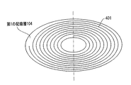
次にアドレス番号について図4A〜図4D、図5A〜図5Dを参照して説明する。図4A、図4B、図4C、図4Dはトラックと記録再生方向とアドレス番号の一例を示す図である。図4Aは第1の記録層104のスパイラル状の溝パターンを示し、図4Bは第2の記録層102のスパイラル状の溝パターンを示し、図4Cは光ディスク100の記録再生方向を示し、図4Dはアドレス番号の割付けを示す。光ディスク100が回転すると、トラック401、もしくはトラック402に沿って、光ヘッド303は内周から外周へと進む。データを順に記録する場合、例えばデータ領域114の最内周から最外周まで記録し、その後、データ領域110の最内周から最外周へと記録される。各記録層の物理アドレス番号403および論理アドレス番号404は記録再生方向の順で増加するように割付けられる。物理アドレス番号403は、0から始まらなくても良いし、1層目と2層目で連続していなくても良い。
【0085】
例えば層番号を物理アドレス番号403に含め、物理アドレス番号403の上位に位置するように設定しても良い。論理アドレス番号404は、ディスクにある全てのデータ領域に対して、0から始まる連続した数字が割付けられ、1層目のデータ領域114において、論理アドレス番号404は最内周で0になり、外周へ進むにつれて1づつ増加し、2層目のデータ領域110において、最内周で1層目の最大番号に1を加えた番号になり、外周へ進むにつれて1づつ増加する。なお405、406は図1には図示していないリードアウト領域と呼ばれる領域であり、光ヘッド303がデータ領域をオーバーランしてもトラックに追随できるように設けられている。
【0086】
図4A〜図4Dに示すようにスパイラル方向の等しい基板を用いることにより、後述するスパイラル方向の異なる基板を製造する場合に比べ、基板製造のプロセスを簡単にすることができる。
【0087】
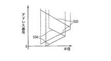
図5A、図5B、図5C、図5Dもトラックと記録再生方向とアドレス番号の一例を示す図である。図5Aは第1の記録層104のスパイラル状の溝パターンを示し、図5Bは第2の記録層102のスパイラル状の溝パターンを示し、図5Cは光ディスク100の記録再生方向を示し、図5Dはアドレス番号の割付けを示す。光ディスク100が回転すると、トラック501もしくはトラック502に沿って、光ヘッド303は、第1の記録層104は内周から外周へ進み、第2の記録層102は外周から内周へと進む。データを順に記録する場合、例えばデータ領域114の最内周から最外周まで記録し、その後、データ領域110の最外周から最内周へと記録される。各記録層の物理アドレス番号503および論理アドレス番号504は記録再生方向の順で増加するように割付けられる。但し、2層目のスパイラルが逆向きであるのでアドレス番号と半径の関係は変わる。論理アドレス番号504は、1層目のデータ領域114において、最内周で0になり、外周へ進むにつれて1づつ増加する。2層目のデータ領域110において、最外周で1層目の最大LSNに1を加えた番号になり、内周へ進むにつれて1づつ増加する。なお505、506は図1には図示していないリードアウト領域と呼ばれる領域であり、光ヘッド303がデータ領域をオーバーランしてもトラックに追随できるように設けられている。
【0088】
図5A、図5B、図5C、図5Dに示すようにデータ領域114の最内周から最外周まで記録し、その後、データ領域110の最外周から最内周へと記録する場合には、特に各記録層固有のパラメータやフォーマット情報を、一つのディスク情報領域にまとめて記録しておくことにより、最外周から最内周のディスク情報領域まで戻る必要がないのでより効果が大きい。
【0089】
同様に再生のみを行う場合でもデータ領域114の最内周から最外周まで再生し、その後データ領域110の最外周から最内周へと再生する場合にも、特に各記録層固有のパラメータやフォーマット情報を、一つのディスク情報領域にまとめて記録しておくことにより、最外周から最内周のディスク情報領域まで戻る必要がないのでより効果が大きい。
【0090】
なおディスク情報領域107および111における各記録層固有のパラメータやフォーマットのレイアウトを図6Aに示す。図6Aにおいて、♯1は第1の記録層104に関係するパラメータおよびフォーマットのうちの少なくとも一方を示し、♯2は第2の記録層102に関係するパラメータおよびフォーマットのうちの少なくとも一方を示す。図6Aに示すディスク情報領域601から603および609に二層ディスクにおけるディスク情報領域のレイアウトを示している。ディスク情報領域601から603および609はディスク情報領域107および111に対応する。ディスク情報領域604が示す情報のレイアウトは単層ディスクにおけるディスク情報領域の情報のレイアウトである。なおディスク情報領域601から603および609における情報のレイアウトとしては、二層ディスクに限らず、多層ディスクについても同様の規則をあてはめることができる。
【0091】
ディスク情報領域601から603および609において、各記録層固有のパラメータやフォーマット情報は複数セットが記録されている。このように複数セットを記録することにより、一つの領域が傷や埃によって再生できなくても他の領域を再生することにより、所望の情報を入手することができる。
【0092】
なおパラメータおよびフォーマットが記録された領域長さは、どの層のパラメータおよびフォーマットが記録された領域についても同一であることが望ましい。これにより情報の開始位置を特定することが可能になり、待ち時間を短縮することができるとともに、繰り返し毎、もしくは記録層毎に開始位置を探索する必要がなくなり、記録再生装置の構成を簡単にすることができる。この場合、例えば、ディスク情報領域のうちの第1の記録層104に関するパラメータおよびフォーマットが格納された領域の長さと、ディスク情報領域のうちの第2の記録層102に関するパラメータおよびフォーマットが格納された領域の長さとが同じである。
【0093】
ディスク情報領域601には、全記録層のパラメータおよびフォーマット情報を1セットとした情報のセットが4回繰り返して記録されている。ディスク情報領域601の残りの領域605には例えばデータ“0”を記録しておく。このとき、記録再生方向が内周側から外周側へ向かう方向のときには、最初に再生する記録層(例えば基準層である第1の記録層104)のパラメータおよびフォーマットを最も内周側に記録しておくことにより、最初に再生する記録層のパラメータおよびフォーマットを速やかに入手することができ、最初に再生する記録層の再生時の照射パワーが正しくない場合でも速やかに照射パワーを訂正することができる。この場合、ディスク情報領域のうちの第1の記録層104に関するパラメータおよびフォーマットが格納された領域に割り当てられたアドレスは、ディスク情報領域のうちの第2の記録層102に関するパラメータおよびフォーマットが格納された領域に割り当てられたアドレスよりも小さくなるように情報を格納する。このとき、ディスク情報領域のうちの第1の記録層104に関する照射パワー情報が格納された領域に割り当てられているアドレスは、ディスク情報領域のうちの第2の記録層102に関する照射パワー情報が格納された領域に割り当てられているアドレスよりも小さくなるように情報が格納される。この特徴により、例えばレーザの照射パワーが高すぎることによるデータの破壊を最小限に抑えることができる。
【0094】
同様に再生方向が外周側から内周側へ向かう方向のときには、最初に再生する記録層の情報を最も外周側に記録しておくことにより、最初に再生する層の再生時の照射パワーが正しくない場合でも速やかに訂正することができる。さらに後述する602と比較して短時間で全ての記録層の情報を再生することができる。
【0095】
第1の記録層104および第2の記録層102に関するパラメータおよびフォーマットの情報量が少ない場合は、第1の記録層104に関するパラメータおよびフォーマットと、第2の記録層102に関するパラメータおよびフォーマットとは、ディスク情報領域のうちの同じアドレスが割り当てられてた領域に格納されてもよい。ここで、第1の記録層104には、光ディスク100の周方向に沿って光ディスク100の内周側から外周側へ向かう方向にアドレスが割り当てられているとする。この場合、ディスク情報領域107が備える上記同じアドレスが割り当てられた領域のうちの第1の記録層104に関するパラメータおよびフォーマットが格納された領域は、上記同じアドレスが割り当てられた領域のうちの第2の記録層102に関するパラメータおよびフォーマットが格納された領域よりも光ディスク100の内周側に配置される。また、第1の記録層104に、光ディスク100の周方向に沿って光ディスク100の外周側から内周側へ向かう方向にアドレスが割り当てられている場合には、ディスク情報領域107が備える上記同じアドレスが割り当てられた領域のうちの第1の記録層104に関するパラメータおよびフォーマットが格納された領域は、上記同じアドレスが割り当てられた領域のうちの第2の記録層102に関するパラメータおよびフォーマットが格納された領域よりも光ディスク100の外周側に配置される。
【0096】
なお、第2の記録層102が備えるディスク情報領域107では、第2の記録層102に関するパラメータおよびフォーマットが格納された領域に割り当てられたアドレスが、ディスク情報領域のうちの第1の記録層104に関するパラメータおよびフォーマットが格納された領域に割り当てられたアドレスよりも小さくなるように情報が格納されてもよい。これにより、第2の記録層102を第1の記録層104よりも先に再生する場合でも、第2の記録層102に関するパラメータおよびフォーマットを速やかに入手することができ、第2の記録層102に照射されるレーザ光の照射パワーが正しくない場合でも速やかに照射パワーを訂正することができる。
【0097】
なおディスク情報領域601の領域605を除く領域の実データ量を示す(例えばバイト単位で示す)情報を、ディスク情報領域の最内周付近に記録しておいても良い。これにより記録再生装置は不要なデータを再生することがなくなり速やかに次の処理を実行することができる。実データ量は記録層毎に異なっていても良く、記録層毎に実データ量をディスク情報領域の最内周付近に記録しておいても良い。
【0098】
またディスク情報領域601では各記録層の情報を1セットづつ記録したものを4回繰り返しているが、繰り返し回数はこれに限らず、また繰り返し回数を示す情報をディスク情報領域601の最内周付近に記録しておいても良い。これにより記録再生装置は不要なデータを再生することがなくなり速やかに次の処理を実行することができる。
【0099】
ディスク情報領域602には記録層ごとのパラメータおよびフォーマット情報を1セットとした情報のセットが4セットずつ記録されている。ディスク情報領域の残りの領域606には例えばデータ“0”を記録しておく。このとき最初に再生する記録層に関する情報を最も内周側に記録しておくことにより、最初に再生する層の再生時の照射パワーが正しくない場合でも速やかに照射パワーを訂正することができる。この場合、ディスク情報領域のうちの第1の記録層104に関するパラメータおよびフォーマットが格納された領域に割り当てられたアドレスは、ディスク情報領域のうちの第2の記録層102に関するパラメータおよびフォーマットが格納された領域に割り当てられたアドレスよりも小さくなるように情報を格納する。さらに単層ディスクのディスク情報領域のレイアウトであるディスク情報領域604の情報のレイアウトと、ディスク情報領域602の内周側の情報のレイアウトとが同一であることから、光ディスク100の再生アルゴリズムを単層ディスクに付加する形式と同じ形式として光ディスク100を製造することができるので、記録再生装置を簡単にすることができる。
【0100】
なおディスク情報領域602の領域606を除く領域の実データ量を示す(例えばバイト単位で示す)情報を、ディスク情報領域の最内周付近に記録しておいても良い。これにより記録再生装置は不要なデータを再生することがなくなり速やかに次の処理を実行することができる。実データ量は記録層毎に異なっていても良く、記録層毎に実データ量をディスク情報領域の最内周付近に記録しておいても良い。
【0101】
またディスク情報領域602では記録層毎の情報を1セットづつ記録したものを4回繰り返して記録しているが、繰り返し回数はこれに限らず、また繰り返し回数を示す情報をディスク情報領域602の最内周付近に記録しておいても良い。これにより記録再生装置は不要なデータを再生することがなくなり速やかに次の処理を実行することができる。なお繰り返し回数は記録層毎に異なっていても良く、記録層毎の情報のセットの繰り返し回数をディスク情報領域602の最内周付近に記録しておいても良い。
【0102】
ディスク情報領域603には、記録再生に必要なパラメータやフォーマット情報を各要素に分けて、全記録層の特定の要素を集めて1セットとした情報のセットが記録されている。繰り返し方法についてはディスク情報領域601のようにまず要素ごとに一通り並べたセットを複数回記録しても良いし、ディスク情報領域602のように要素毎に複数回記録してから他要素の情報を記録しても良い。
【0103】
またディスク情報領域603においても、ディスク情報領域の残りの領域607には例えばデータ“0”を記録しておいても良い。さらに最初に再生する記録層の情報を最も内周側に記録しておくことにより、最初に再生する層の再生時の照射パワーが正しくない場合でも照射パワーを速やかに訂正することができる。
【0104】
なおディスク情報領域603の領域607を除く領域の実データ量を示す(例えばバイト単位で示す)情報を、ディスク情報領域603の最内周付近に記録しておいても良い。これにより記録再生装置は不要なデータを再生することがなくなり速やかに次の処理を実行することができる。
【0105】
またディスク情報領域601から604において、パラメータやフォーマット情報を記録した残りの領域に所定のデータを記録しておくことにより、サーボ回路205により光ヘッド203をディスク情報領域に移動させる際に、所定のデータを再生することによってディスク情報領域であることを速やかに認識することができる。
【0106】
なおディスク情報領域601から603は、図4Dや図5Dにおけるアドレス番号が増加する方向に、各記録層に関する情報の記録を行っており、例えば図5Dのようにスパイラル方向が逆になっている場合では、1層目の記録層と2層目の記録層とで物理的な配置は逆になる。例えば1層目の記録層はディスク情報領域の最内周部から記録を行い、2層目の記録層はディスク情報領域は最外周部から記録を行っているが、配置方法はこれに限らず、1層目も2層目の記録層もディスクの最内周部から記録を行って良い。
【0107】
なおディスク情報領域601から603において各記録層に共通のパラメータやフォーマット情報やディスク情報については、層毎の情報の記録に先だって記録を行って良い。ディスク情報領域609には、このような記録方法に従ってパラメータおよびフォーマットが記録されている。共通項目をまとめることにより、層数が多いほどディスク情報領域を節約することができる。なお共通項目についても図6Aの情報♯1、♯2と同様の扱いとし複数回記録を行うことにより、一つの領域が傷や埃によって再生できなくても他の領域を再生することにより、所定の情報を入手することができる。
【0108】
なお各記録層の共通項目を記録する領域の長さは、各記録層の情報を記録する長さの倍数であることが望ましい。これにより、層数や共通項目の量が変わっても情報の開始位置を記録再生装置が予測することが容易になり、待ち時間を短縮することができるとともに記録再生装置の構成を簡単にすることができる。
【0109】
次に図6Bに、ディスク情報領域601の改変例であるディスク情報領域1101、1102、1103および1104を示す。ディスク情報領域1101、1102、1103および1104は複数のダミー領域1100を含む。
【0110】
ディスク情報領域1101では、全ての記録層に関するパラメータおよびフォーマットのセットの情報が繰り返し記録されており、セットの情報が記録された各領域の間にダミー領域が配置されている。これによりダミー領域を検出することで、直後の領域に情報♯1が記録されていること、又は直前の領域に情報♯2が記録されていることを認識することができる。これにより情報♯1、♯2の各情報内に自身を示す識別子を設ける必要がなくなり、記録再生装置の構成を簡単にすることができるとともに処理時間を短縮することができる。
【0111】
なおダミー領域にはディスク情報領域の残りの領域1105に記録する内容と同一の内容(例えばデータ“0”)を記録しても良いし、異なる内容を記録しても良い。異なる内容を記録することにより、直後の領域に情報♯1が記録されていること、又は直前の領域に情報♯2が記録されていることを明確に認識することができる。また同一の内容を記録した場合でも記録長を変えることにより領域1105との違いが明確になり、同様の効果が得られる。
【0112】
さらにディスク情報領域609(図6A)に示す様にダミー領域に情報♯1、♯2共通の情報を記録することで、直後の領域に情報♯1が記録されていること、又は直前の領域に情報♯2が記録されていることを認識することができることに加え、共通情報の取得が容易になる。
【0113】
なおディスク情報領域1102に示す様に、ダミー領域1100を領域1106に隣接して記録しても良く、これにより、少なくとも直前の領域に情報♯2が記録されていることを認識することができる。なおディスク情報領域1102における最後のダミー領域のみ、他のダミー領域と記録内容が異なっていても良い。これにより繰り返し記録が終了することを明確にすることができる。
【0114】
さらにダミー領域の長さを、ディスク情報領域1103に示す様に、情報♯1、情報♯2の1セットを記録する領域の長さの整数倍にしてもよい。このことにより、層数が異なる場合でも各記録層の情報の開始位置を予測することが容易になり、待ち時間を短縮することができるとともに再生装置の構成を簡単にすることができる。
【0115】
またディスク情報領域1104に示す様にダミー領域1100を最初の情報♯1、情報♯2が記録された領域の前にも記録しても良い。これにより、少なくとも直後の領域に情報♯1が記録されていることを認識することができる。なおディスク情報領域1104における最初のダミー領域のみ、他のダミー領域と記録内容が異なっていても良い。これにより繰り返し記録が開始することを明確にすることができる。
【0116】
なお最初のダミー領域の設定方法については、ディスク情報領域とその直前の領域との違いを認識することができれば本方法に限らなくとも良く、ディスク情報領域の直前領域のトラック形状や、トラック形状に情報を重畳する際の変調方式の違い等から、ディスク情報領域との違いを認識しても良い。
【0117】
なお図6Bに示したダミーデータはディスク情報領域602に対しても使用可能であり、ディスク情報領域601に適用した場合と同等の効果が得られる。
【0118】
以上の様に、各記録層に記録再生を行う際に必要となる各記録層固有のパラメータやフォーマット情報を、1つのディスク情報領域にまとめて記録しておくことにより、複数の層に配置された複数のディスク情報領域を再生する場合と比較して、複数層のデータを記録再生する際の所要時間を短縮することができる。
【0119】
なお本実施の形態ではディスク情報領域を中心に説明したが、欠陥リスト領域、スペア領域についても各記録層の情報をまとめて一つの層に記録しておくことにより、同様の効果が得られる。
【0120】
なお本実施の形態では、各記録層に記録再生を行う際に必要となる、各記録層固有のパラメータやフォーマット情報を、1つのディスク情報領域にまとめて記録しているが、1つのディスク情報領域にまとめて記録せずに複数のディスク情報領域に分けて記録しても良いし、所定の必須項目については各記録層の情報を1つのディスク情報領域にまとめ、その他の項目については自層のディスク情報領域のみに記録しても良い。
【0121】
なお欠陥リスト領域108、スペア領域109、データ領域110、欠陥リスト領域112、スペア領域113、データ領域114におけるトラックに、ディスク情報領域に記録されているパラメータやフォーマットを記録する際にも図6Aと図6Bとに示すようなレイアウトに従って情報が記録されていても良い。
【0122】
次に、図9を参照して本発明のさらなる実施の形態における書き換え型光ディスク900について説明する。
【0123】
図9に示す光ディスク900は、第1の基板905と、第1の記録層904と、接着樹脂903と、第2の記録層902と、第2の基板901とを備える。各基板および各記録層にはクランプ穴906が形成されている。光ディスク900は、ユーザデータを記録するためのデータ領域920を備える。データ領域920は第1の記録層904と第2の記録層902との両方に渡って配置されている。データ領域920の一部であるデータ領域912が第2の記録層902に配置されおり、データ領域920の一部であるデータ領域918が第1の記録層904に配置されている。
【0124】
第2の記録層902は、ディスク情報領域907と、第1の欠陥リスト領域908と、テスト記録領域909と、第2の欠陥リスト領域910と、スペア領域911と、データ領域912とを備える。
【0125】
第1の記録層904は、ディスク情報領域913と、第1の欠陥リスト領域914と、テスト記録領域915と、第2の欠陥リスト領域916と、スペア領域917と、データ領域918とを備える。
【0126】
第1の記録層904と第2の記録層902とは、光ディスク900の片面に設けられている。
【0127】
各記録層において第1の欠陥リスト領域と第2の欠陥リスト領域とには同じデータが記録されていることが望ましい。また全ての記録層の欠陥リスト領域に同じデータが記録されていても良い。これにより記録時や再生時にレーザ光のスポットが記録層間を移動した際に、移動先の層の欠陥リスト領域を再度再生するための時間を節約することができる。
【0128】
テスト記録領域909はデータ領域912に情報を記録するためのレーザ光の記録パワーを調整するためにテスト記録を行う調整領域として機能する。同様にテスト記録領域915はデータ領域918に情報を記録するためのレーザ光の記録パワーを調整するためにテスト記録を行う調整領域として機能する。本実施の形態のように各記録層毎にテスト記録領域を設けることにより、各記録層に適した記録条件を決定することができる。
【0129】
ところで一般に一方の層から他方の層への垂直方向のレーザ光のスポットの移動において、基板の貼り合わせのずれや、各基板のクランプ穴の位置ずれ等により同一半径位置に移動することは難しい。例えば第1の記録層904の内側から1000トラック目の位置から、第2の記録層902の内側から1000トラック目の位置に移動しようとしても±50トラック程度のずれが生じる。
【0130】
またテスト記録領域では記録条件を決定するために、サーボ的にも不安定な記録条件でテスト記録を行うことから、記録中にトラッキングが外れたり、別の層でフォーカスが瞬間的に最適となる危険性がある。そこで各記録層のテスト記録領域の前後に隣接して使用目的を規定しないバッファ領域を設けることが望ましく、また図9に示すように欠陥リスト領域をテスト記録領域の前後に複数個設けることが望ましい。各記録層においてテスト記録領域の前後に欠陥リスト領域を設けることにより、データの記録中にトラッキングが外れても欠陥リスト領域の全データが破壊される危険性を低減することができる。また、ある記録層への情報の記録中にフォーカスが外れても、他の記録層の欠陥リスト領域の全データが破壊される危険性を低減することができる。
【0131】
また本実施の形態では欠陥リスト領域は各記録層の内周部にしか設けていないが、同様の観点から外周部に設けても良い。外周部に設けることによりテスト記録に起因する欠陥リスト領域のデータの破壊を防止することができる。
【0132】
なお各記録層固有のパラメータやフォーマット情報を一つのディスク情報領域にまとめて記録しても良いし、記録層が別々に独立してパラメータやフォーマット情報を含んでもよい。
【0133】
また、図10に示すように各記録層のテスト記録領域はそれぞれ異なる半径位置に配置されても良い。光ディスク900の改変例である図10に示す光ディスク1000は、第1の基板1005と、第1の記録層1004と、接着層1003と、第2の記録層1002と、第2の基板1001とを備える。
【0134】
第2の基板1001、第2の記録層1002、接着層1003、第1の記録層1004、第1の基板1005は、第2の基板901、第2の記録層902、接着層903、第1の記録層904、第1の基板905に対応する。第2の記録層1002、第1の記録層1004は、第2の記録層902、第1の記録層904と同じ構成要素を有するが、テスト記録領域の配置位置が異なる。第2の記録層1002はテスト記録領域1008を備える。第1の記録層1004はテスト記録領域1007を備える。
【0135】
参照符号1009は入射光、参照符号1010は第2の記録層1002からの反射光、参照符号1011は第2の記録層1002の透過光、参照符号1012は第1の記録層1004からの反射光、参照符号1013は第2の記録層1002の透過光をそれぞれ示し、レーザ光の進行の様子を表している。第2の記録層1002を再生しているときには、反射光1010が主要な再生光であり、透過光1013が不要な迷光である。また第1の記録層1004を再生しているときには、透過光1013が主要な再生光であり、反射光1010が不要な迷光である。
【0136】
ここで、仮に、記録層1004にデータを記録するのに最適なレーザ光の照射パワーを決定するためのテスト記録領域が領域1006の位置に配置されていたとする。この場合、テスト記録領域1008が(例えば繰り返し記録により)劣化もしくは破壊されていると、第2の記録層1002での透過係数や反射係数が変化し、透過光1011、反射光1010、透過光1013の光量がそれぞれ変化する。これにより、テスト記録領域1008が正常な場合と異なり、テスト記録領域1006を用いて求められる照射パワーの値は、正しい照射パワーの値から外れてしまうという問題が生じる。
【0137】
図10に示すように、テスト記録領域1007およびテスト記録領域1008のそれぞれを光ディスク1000の異なる半径位置に配置することにより、テスト記録領域1008が劣化または破壊された場合でも、第1の記録層1004に適したレーザ光の照射パワーの値を正しく決定することができる。
【0138】
このように各記録層のテスト記録領域を互いに異なる半径位置に配置することは、光ディスク1000が1回のみ記録が可能な追記型光ディスク、特に光学特性が記録により変化し、不可逆である記録膜を有する光ディスクである場合に非常に有効であり、本発明はこのような1回のみ記録が可能な光ディスクにも適用される。
【0139】
なお本実施の形態では、各記録層のテスト記録領域をそれぞれ異なる半径位置に配置しているが、テスト記録領域に限らず、例えば光ディスクに記録されているデータのリストを一括的に管理する領域等、繰り返し記録回数が通常のユーザデータを記録する領域よりも多くなる領域も各記録層毎に異なる半径位置に配置しても良い。異なる半径位置に配置することにより、一方の層の上記領域が劣化した場合の他層の上記領域への影響を防止することができ、他層の上記領域への正しい記録再生を行うことができる。
【0140】
なお本実施の形態では、2つのテスト記録領域1007とテスト記録領域1008とにおいて、テスト記録領域1007の方を半径方向で外周側に配置しているが、テスト記録領域1008の方を半径方向で外周側に配置しても良い。例えば図5Cに示すような記録再生方向のとき、テスト記録領域1007を内周側から使用し、テスト記録領域1008を外周側から使用することにしてもよい。これにより、テスト記録領域1008を使用する際に、テスト記録領域1007の最も外周側を使用していない確率が、逆に配置した場合よりも高くなる。これにより、テスト記録領域1007の劣化によるテスト記録1008への影響をさらに小さくすることができる。この効果は特に1回のみ記録が可能な光ディスクにおいて非常に大きい。
【0141】
なお本実施の形態ではテスト記録領域は内周側にのみ設けられているが、外周側にも設けられていても良い。
【0142】
本発明は、記録可能な記録層を有する光ディスクに限定されず、複数の再生専用の記録層のみを有する光ディスクにおいてもディスク情報領域を有していれば本発明により同様の効果を有する。
【0143】
また本実施の形態では第1の記録層と第2の記録層の二つの層に記録を行う場合について説明したが、本発明は、単層ディスクの場合に適用しても同様の効果を有する。
【0144】
なお本実施の形態では主に書き換え型の光ディスクについて説明したが、本発明は、1回もしくは数回だけ記録可能な光ディスクにおいても同様の効果を有する。
【0145】
【発明の効果】
本発明の光ディスクによれば、各記録層に記録再生を行う際に必要となる各記録層固有のパラメータおよびフォーマットを1つのディスク情報領域にまとめて記録している。この特徴により、1つのディスク情報領域から全記録層のパラメータおよびフォーマットを再生することが出来るので、複数の記録層に対するデータの記録再生時間を短縮することができる。
【図面の簡単な説明】
【図1】本発明の実施の形態における光ディスクを示す図
【図2A】本発明の実施の形態における記録層に形成されたトラックを示す図
【図2B】本発明の実施の形態における記録層に形成されたトラックを示す図
【図2C】本発明の実施の形態における記録層に形成されたトラックを示す図
【図2D】本発明の実施の形態における記録層に形成されたトラックを示す図
【図3】本発明の実施の形態における記録再生装置を示す図
【図4A】本発明の実施の形態におけるトラックを示す図
【図4B】本発明の実施の形態におけるトラックを示す図
【図4C】本発明の実施の形態における記録再生方向を示す図
【図4D】本発明の実施の形態における記録層へのアドレス番号の割り当てを示す図
【図5A】本発明の実施の形態におけるトラックを示す図
【図5B】本発明の実施の形態におけるトラックを示す図
【図5C】本発明の実施の形態における記録再生方向を示す図
【図5D】本発明の実施の形態における記録層へのアドレス番号の割り当てを示す図
【図6A】ディスク情報領域の情報のレイアウトを示す図
【図6B】ディスク情報領域の情報のレイアウトを示す図
【図7】光ディスクを示す図
【図8A】本発明の実施の形態における光ディスクを示す図
【図8B】本発明の実施の形態における光ディスクを示す図
【図9】本発明の実施の形態における光ディスクを示す図
【図10】本発明の実施の形態における光ディスクを示す図
【符号の説明】
101 第2の基板
102 第2の記録層
103 接着樹脂
104 第1の記録層
105 第1の基板
106 クランプ穴
107 ディスク情報領域
108 欠陥リスト領域
109 スペア領域
110 データ領域
300 光ディスクドライブ
301 光ディスク
302 スピンドルモータ
303 光ヘッド
304 レーザ光制御回路
305 サーボ回路[0001]
TECHNICAL FIELD OF THE INVENTION
The present invention relates to an information recording medium having at least two recording layers, a recording device, a reproducing device, a recording method, and a reproducing method.
[0002]
[Prior art]
In recent years, various information recording media capable of recording and reproducing a large amount of information have been developed, and one of them is an optical disk. As one of the large-capacity optical disks, there is a double-sided optical disk capable of laminating two optical disks and recording and reproducing on both surfaces. However, in fields that frequently require random access, for example, a recording medium for a computer or a recording medium for a game, it is desired that the recording capacity of an optical disk is large and that arbitrary data can be accessed without turning over.
[0003]
Therefore, a multi-layer optical disc which has two or more recording layers and can reproduce information from one side of the disc can be considered as an optical disc that records a large amount of data on one optical disc and is randomly accessible. FIG. 7 shows a configuration of an
[0004]
The
[0005]
The first substrate 705 and the second substrate 701 are formed of a polycarbonate resin or the like, and protect the
[0006]
[Problems to be solved by the invention]
In the
[0007]
SUMMARY OF THE INVENTION The present invention has been made in view of the above circumstances, and has as its object to reduce the time for reproducing a disc information area.
[0008]
[Means for Solving the Problems]
The information recording medium of the present invention includes a plurality of recording layers, and a disk information area in which a parameter relating to access to the plurality of recording layers and a format relating to the plurality of recording layers are stored. The first recording layer, which is one of the plurality of recording layers, is arranged, thereby achieving the above object.
[0009]
An address is assigned to the first recording layer, and the parameter includes first irradiation power information indicating a value of power of a laser beam applied to the first recording layer, and information of the plurality of recording layers. And second irradiation power information indicating the value of the power of the laser light irradiating the other recording layer, and the second irradiation power information is assigned to an area of the disc information area where the first irradiation power information is stored. The address at which the second irradiation power information is stored in the disc information area may be smaller than the address assigned to the area where the second irradiation power information is stored.
[0010]
The information processing apparatus further includes a further disc information area storing the same information as the disc information area, wherein the further disc information area is arranged on a second recording layer that is another one of the plurality of recording layers. Good.
[0011]
The first recording layer may be a recording layer predetermined as a reference layer among the plurality of recording layers.
[0012]
The plurality of recording layers are recording layers on which information can be written, the information recording medium further includes a plurality of adjustment regions for adjusting recording power of laser light, and each of the plurality of recording layers is A corresponding one of the plurality of adjustment regions may be provided.
[0013]
A second recording layer, which is one of the plurality of recording layers, includes a buffer area, and the buffer area is adjacent to an adjustment area of the second recording layer of the plurality of adjustment areas. It may be arranged.
[0014]
Each of the plurality of adjustment areas may be arranged at a different radial position of the information recording medium.
[0015]
The information recording medium may be a write-once information recording medium.
[0016]
An address is assigned to the first recording layer, and the parameter includes a first parameter relating to access to the first recording layer and a parameter relating to access to another recording layer of the plurality of recording layers. And an address assigned to an area of the disc information area where the first parameter is stored, the address being assigned to an area of the disc information area where the second parameter is stored. It may be smaller than the address that is used.
[0017]
An address is assigned to the first recording layer, and the format includes a first format related to the first recording layer and a second format related to another of the plurality of recording layers. The address assigned to the area of the disk information area where the first format is stored is smaller than the address assigned to the area of the disk information area where the second format is stored. You may.
[0018]
A data area for recording user data formed on the plurality of recording layers; a groove formed in the plurality of recording layers; a second area being one of the plurality of recording layers; In the recording layer, an area at the same radial position as the disc information area as a part of the second recording layer and a part of the data area as another part of the second recording layer are arranged. The shape of the shape of the groove formed in the area at the same radial position as the disc information area is the same as the form of the shape of the groove formed in the area where a part of the data area is arranged. It may be.
[0019]
A groove is formed in at least a part of the plurality of recording layers, and the second recording layer that is one of the plurality of recording layers is the disk that is a part of the second recording layer. It is not necessary to have a groove in the area at the same radial position as the information area.
[0020]
A groove may be formed in the plurality of recording layers, and the shape of the shape of the groove in the second recording layer, which is one of the plurality of recording layers, may be constant.
[0021]
A groove is formed in the first recording layer, and the shape of the groove in the disk information area and the shape of the groove in an area adjacent to the disk information area that is a part of the first recording layer May be different.
[0022]
A groove is formed in the first recording layer, and a groove in the disk information area and a groove in an area adjacent to the disk information area, which is a part of the first recording layer, are continuous. Is also good.
[0023]
The parameter and the format include a first parameter and a first format related to the first recording layer, and the parameter and the format are a second one that is another one of the plurality of recording layers. The disk information area includes a second parameter and a second format, the length of the area in which the first parameter and the first format of the disk information area are stored, and the length of the area of the disk information area. The length of the area in which the second parameter and the second format are stored may be the same.
[0024]
The parameter includes a first parameter relating to access to the first recording layer, the format includes a first format relating to the first recording layer, and the disc information area includes the first parameter and the first parameter. A set with one format may be stored continuously and repeatedly.
[0025]
The parameter includes a second parameter related to access to a second recording layer that is another one of the plurality of recording layers, the format includes a second format related to the second recording layer, A set of the second parameter and the second format may be continuously and repeatedly stored in the disc information area.
[0026]
The disk information area may store a plurality of pairs of the parameter and the format.
[0027]
A dummy area, wherein the plurality of sets include a first set and a second set, wherein the dummy area includes an area in which the first set, which is a part of the disc information area, is arranged; The second set, which is another part of the disk area, may be arranged between the second area and the area where the second set is arranged.
[0028]
The length of the dummy area may be an integral multiple of the length of the area in which the set of the parameter and the format is stored.
[0029]
An address is assigned to the first recording layer, and the parameter includes a first parameter relating to access to the first recording layer and an access to another recording layer of the plurality of recording layers. And the second parameter may be stored in an area of the disk information area to which the same address is assigned.
[0030]
An address is assigned to the first recording layer, and the format includes a first format relating to the first recording layer and a second format relating to another recording layer of the plurality of recording layers. And the first format and the second format may be stored in an area of the disc information area to which the same address is assigned.
[0031]
In the recording apparatus for recording information on the information recording medium of the present invention, the information recording medium stores a plurality of recording layers, a parameter relating to access to the plurality of recording layers, and a format relating to the plurality of recording layers. A disc information area, wherein the disc information area is arranged on a first recording layer that is one of the plurality of recording layers, and the recording device stores the information on the information recording medium. An optical head that can be optically written, and a control unit that controls execution of a recording process using the optical head unit, wherein the recording process is performed by using the parameter and the parameter stored in the disc information area. Reproducing the format, and recording the information on the information recording medium based on the reproduced parameters and format. And including, the object is achieved.
[0032]
In a reproducing apparatus for reproducing information recorded on an information recording medium of the present invention, the information recording medium includes a plurality of recording layers, a parameter relating to access to the plurality of recording layers, and a format relating to the plurality of recording layers. And a disc information area in which the disc information area is disposed in a first recording layer, which is one of the plurality of recording layers. An optical head unit that can optically read the recorded information; and a control unit that controls execution of a reproduction process using the optical head unit. The reproduction process is stored in the disc information area. Reproducing the reproduced parameters and the format, and, based on the reproduced parameters and the format, recorded on the information recording medium. It includes a step of reproducing the serial information, the objects can be achieved.
[0033]
In the recording method for recording information on an information recording medium of the present invention, the information recording medium stores a plurality of recording layers, a parameter relating to access to the plurality of recording layers, and a format relating to the plurality of recording layers. A disc information area, wherein the disc information area is disposed on a first recording layer, which is one of the plurality of recording layers, and the recording method includes the steps of: A step of reproducing the parameters and the format, and a step of recording the information on the information recording medium based on the reproduced parameters and the format, thereby achieving the object.
[0034]
In a reproducing method for reproducing information recorded on an information recording medium according to the present invention, the information recording medium includes a plurality of recording layers, a parameter relating to access to the plurality of recording layers, and a format relating to the plurality of recording layers. Is stored in a first recording layer, which is one of the plurality of recording layers, and the reproducing method includes: Reproducing the stored parameters and the format, and reproducing the information recorded on the information recording medium based on the reproduced parameters and the format, thereby achieving the object. Achieved.
[0035]
BEST MODE FOR CARRYING OUT THE INVENTION
Hereinafter, an optical disc according to an embodiment of the present invention will be described with reference to the drawings.
[0036]
FIG. 1 shows a rewritable
[0037]
The
[0038]
The
[0039]
The
[0040]
Here, the defect list area 108, the spare area 109, the
[0041]
The first substrate 105 and the second substrate 101 are formed of a polycarbonate resin or the like, and protect the
[0042]
As in the present embodiment, the shape of the groove shape of the read-only area such as the
[0043]
In a multilayer disc, it is expected that the irradiation power of the laser beam when reproducing the layer farthest from the disk surface on which reading is performed is larger than the irradiation power of the laser beam when reproducing the single-layer disc. Therefore, when the
[0044]
FIG. 3 shows a recording / reproducing
[0045]
An optical disc 100 (FIG. 1) is mounted on the recording / reproducing
[0046]
The
[0047]
The
[0048]
The digital
[0049]
When the
[0050]
Since the parameters and formats (irradiation power information and the like when recording) of both the
[0051]
Further, since the parameters and the format are recorded in both the
[0052]
Further, as in the present embodiment, since irradiation power information and the like are recorded in both the
[0053]
In this embodiment, the recording is performed on the two layers of the
[0054]
In the present embodiment, both the
[0055]
The track pitches (or radial pit pitches) of the
[0056]
Also, by expanding the track pitch or pit pitch of the disc information area beyond the track pitch or pit pitch of a recordable area such as the data area, the disc information area can be reproduced even in an optical disc apparatus having an optical head having a long laser wavelength, for example. And the minimum information can be returned to the user. That is, by expanding the compatibility between different types of disc information areas, even if recording is not possible due to specifications, the reason why recording cannot be performed can be clarified.
[0057]
In general, in the movement of a laser beam spot in the vertical direction from one layer to the other layer, it is difficult to move to the same radius position due to misalignment of bonding of substrates or misalignment of clamp holes of each substrate. . For example, when trying to move from the position of the 1000th track from the inner circumference of the
[0058]
Therefore, even if the track pitches of the
[0059]
In this embodiment, in the disk information area, as shown in FIG. 2A, disk information is recorded by modulating the track in the radial direction at the basic period and the double period. In the defect list area, spare area, and data area, as shown in FIG. 2B, FIG. 2C, and FIG. 2D, address information and the like are recorded by partial frequency modulation on a track meandering at a predetermined cycle or by superimposition of harmonic components. Have been. In all or a part of the track pitch transition area, the track may be formed by a modulation method which is not in any of the disc information area, the defect list area, the spare area, and the data area. It does not have to be, or even meandering.
[0060]
In this way, by making the modulation method and the form of the track pitch change area different from those before and after the track pitch change area, the recording / reproducing
[0061]
By eliminating discontinuous portions between regions having different track pitches as described above, the spot of the laser beam on the optical disc having the discontinuous portions moves far away from the source of the discontinuous portions in the radial direction and then moves to the destination. As compared with the case, the processing in the destination area can be started promptly.
[0062]
Further, in the present embodiment, the disc information area is provided on the innermost circumference side of the disc, but may be provided on the outermost circumference side, and further provided on both the innermost circumference side and the outermost circumference side. Is also good.
[0063]
In this embodiment, the irradiation power information and the like for recording on the first recording layer and the second recording layer are recorded in both the
[0064]
The reference layer is a recording layer in which the distance from the disk surface on the side from which the optical disk having one recording layer is read to the recording layer and the distance from the disk surface on the side from which the
[0065]
Note that the greater the distance from the disk surface, the greater the degradation of the reproduced signal due to tilt. For this reason, it is desirable that the reference layer, which is almost the same layer as the disk provided with one recording layer at a distance from the disk surface, be the layer farthest from the disk surface. At this time, the shape of the groove shape in the area of the recording layer other than the reference layer and at the same radial position as the disc information area of the reference layer is changed to the groove shape of the data area for recording user data. By using the same shape as the shape, the transmittance can be made the same regardless of the radial position. This eliminates the need for special detection means for reproducing the disc information area of the reference layer, simplifies the configuration of the recording / reproducing apparatus, and further facilitates the production of the recording layer.
[0066]
In particular, in a multi-layer disc having a plurality of recording layers, the substrate is manufactured by setting the groove shape of the recording layer other than the reference layer to the same groove shape as that of the data area. It will be very easy.
[0067]
Further, when the disc information area is provided in the reference layer, a part of the recording layer other than the reference layer and the area at the same radial position as the disc information area of the reference layer has a flat structure having no groove. In addition, it is possible to reduce the scattering of light in the recording layers other than the reference layer, and to improve the reproduction signal quality of the reference layer.
[0068]
In addition, by providing the disc information area only in the reference layer, it is possible to easily determine whether the recording layer being reproduced is the reference layer by reproducing near the radial position where the disc information area of the optical disc is arranged. .
[0069]
The disc information area is a combination of a plurality of irradiation powers at the time of recording, a recommended irradiation power information at the time of reproduction, a recommended irradiation power information at the time of recording, a maximum irradiation power information, a pulse width at the time of recording, and a parameter at the time of recording. In this case, a ratio of the cases, a margin constant used for determining an optimum irradiation power for recording, and the like can be stored.
[0070]
The disc information area includes, as formats relating to a plurality of recording layers, a disc name, a disc size, version information, a disc type of an arbitrary layer (that is, an identifier indicating whether the layer is a recordable / reproducible layer or a read-only layer), and is recordable. The total number of layers, the total number of layers dedicated to reproduction, and the total number of all layers may be stored. Further, in the disc information area, as a format relating to a plurality of recording layers, an identifier indicating whether or not information of an arbitrary layer can be copied, clock information, and BCA (Burst Cutting Area) for adding unique information after manufacturing the disc are arranged. An identifier indicating whether or not, a transfer rate, a recording / reproducing direction, a physical address start number, a physical address end number, a logical address start number, a logical address end number, a shortest mark length, a recording speed, and the like can be stored.
[0071]
By setting parameters necessary for recording and reproduction for each recording layer, the degree of freedom in disc design can be increased. For example, in realizing high-density recording, when information is recorded on a plurality of recording layers, it is necessary to consider variations in reflection of at least other layers through which light passes. Therefore, a design with higher accuracy is required as compared with the case where recording is performed on only one recording layer. At this time, for example, if the
[0072]
Furthermore, by recording parameters necessary for recording and reproduction of an arbitrary layer in the disk information area of at least one recording layer, it is possible to immediately grasp an optimal control method for the entire disk.
[0073]
In the BCA, discs having the same contents in the disc information area are classified in more detail, and barcode recording is performed at a factory after the disc is manufactured. The BCA should be arranged at least one layer, preferably on the reference layer. At this time, by making the groove shape different from that of the reference layer in the layer where no BCA exists, it is possible to easily determine whether or not the layer is the reference layer by reproducing the radius range where the BCA is arranged in the reference layer. In particular, in a recording layer other than the reference layer, by setting the radius range where the BCA is arranged to be a flat structure having no groove, light scattering in other layers can be reduced, and the reproduction signal quality of the BCA can be reduced. Can be improved and the manufacture of the substrate is facilitated.
[0074]
Note that the recording of BCA information is performed by irradiating the laser with a much larger output than recording on the recordable area, so that the properties of the recording film in the recordable area such as a defect list area, a spare area, and a data area are not considered. Risk of damage. For this reason, it is desirable that the BCA is not arranged in a recordable area including a recording position variation. If the recordable area is made to be close to the area where the BCA is arranged, it is desirable to provide a buffer area that does not define the purpose of use between the areas, but in this case, the capacity of the net recordable area decreases. .
[0075]
From the above viewpoint, it is desirable that the area where the normal BCA is arranged is provided at the end in the radial direction. In addition, it is not preferable that the BCA information is normally required at the time of startup and that the BCA is arranged on the outer peripheral side from the viewpoint of capacity. As shown in FIG. 8A, it is desirable to provide the disk information area further inside. In addition, as described above, when recording BCA information, laser irradiation is performed with a large output, so that there is a risk of destroying recorded data in the read-only area. For this reason, as shown in the disk information area 801A in FIG. 8B, a buffer section in which dummy data such as data “0” is recorded is provided in the inner peripheral part of the disk information area, and the actual data is stored in the disk information area 801B in the outer peripheral part. May be recorded.
[0076]
In this embodiment, the disc information is recorded by modulating the tracks in the radial direction at the basic cycle and the double cycle in the disc information area. However, the area where the BCA is arranged uses a different modulation method from the disc information area. Alternatively, it may be a straight groove that does not perform any modulation, or may meander at a predetermined cycle. Further, the track pitch may be different between the area where the BCA is arranged and the disk information recording area. Also in this case, there is a risk that the track groove may be damaged due to the recording of the BCA information. Therefore, it is desirable that the track pitch is made wider in the area where the BCA is arranged.
[0077]
As described above, the recording / reproducing apparatus can quickly discriminate between the area where the BCA is arranged and the disc information recording area by making the modulation scheme and the form of the track different.
[0078]
By the way, it is generally difficult in the vertical movement from one recording layer to the other recording layer to move to the same radius position due to misalignment of the substrates, misalignment of the clamp holes of each substrate, and the like. For example, an attempt to move from the 1000th track from the inner circumference of the
[0079]
It is desirable that the irradiation power information at the time of reproduction be recorded prior to the irradiation power information at the time of recording. Thus, when the request from the host PC is at the time of reproduction, the irradiation power information at the time of recording is not reproduced. Data can be reproduced.
[0080]
Parameters and formats necessary for recording / reproducing an arbitrary layer recorded in the disc information area on tracks in the defect list area 108, the spare area 109, the
[0081]
The recording method of the parameters and the format may be the same as the recording method of the address information in each area, or may be a recording method different from the recording method of the address information.
[0082]
Even if parameters and formats recorded in the disc information area are not recorded in all areas such as the defect list area 108, the spare area 109, the
[0083]
Note that the parameters and formats of all layers do not have to be recorded in the tracks in the defect list area 108, the spare area 109, the
[0084]
Next, the address numbers will be described with reference to FIGS. 4A to 4D and FIGS. 5A to 5D. 4A, 4B, 4C, and 4D are diagrams showing an example of a track, a recording / reproducing direction, and an address number. 4A shows a spiral groove pattern of the
[0085]
For example, the layer number may be included in the
[0086]
By using substrates having the same spiral direction as shown in FIGS. 4A to 4D, the substrate manufacturing process can be simplified as compared with the case of manufacturing substrates having different spiral directions described later.
[0087]
FIGS. 5A, 5B, 5C, and 5D are also diagrams showing examples of tracks, recording / reproducing directions, and address numbers. 5A shows a spiral groove pattern of the
[0088]
As shown in FIGS. 5A, 5B, 5C, and 5D, when recording is performed from the innermost circumference to the outermost circumference of the
[0089]
Similarly, even in the case where only the reproduction is performed, the reproduction from the innermost circumference to the outermost circumference of the
[0090]
FIG. 6A shows a layout of parameters and formats unique to each recording layer in the
[0091]
In the
[0092]
It is desirable that the length of the area where the parameters and the format are recorded be the same for the area where the parameters and the format of any layer are recorded. This makes it possible to specify the start position of the information, shorten the waiting time, eliminate the need to search for the start position for each repetition or for each recording layer, and simplify the configuration of the recording / reproducing apparatus. can do. In this case, for example, the length of the area where the parameters and the format related to the
[0093]
In the
[0094]
Similarly, when the reproduction direction is from the outer circumference to the inner circumference, by recording the information of the recording layer to be reproduced first on the outermost side, the irradiation power at the time of reproduction of the layer to be reproduced first can be correctly adjusted. If not, they can be corrected promptly. Further, information of all recording layers can be reproduced in a shorter time as compared with 602 described later.
[0095]
When the information amount of the parameters and the format regarding the
[0096]
In the
[0097]
Information indicating the actual data amount (for example, in units of bytes) of the area of the
[0098]
In the
[0099]
In the
[0100]
Note that information indicating the actual data amount (in units of bytes, for example) of the area other than the
[0101]
In the
[0102]
In the
[0103]
Also in the
[0104]
Note that information indicating the actual data amount (in units of bytes, for example) of the area other than the
[0105]
In the
[0106]
In the
[0107]
In the
[0108]
It is desirable that the length of the area for recording the common item of each recording layer is a multiple of the length of recording the information of each recording layer. This makes it easy for the recording / reproducing device to predict the start position of information even when the number of layers or the amount of common items changes, thereby reducing the waiting time and simplifying the configuration of the recording / reproducing device. Can be.
[0109]
Next, FIG. 6B shows
[0110]
In the
[0111]
In the dummy area, the same content (for example, data “0”) as the content to be recorded in the remaining
[0112]
Furthermore, by recording information common to the
[0113]
As shown in the
[0114]
Further, as shown in the
[0115]
As shown in the
[0116]
The method of setting the first dummy area is not limited to this method as long as the difference between the disc information area and the area immediately before the disc information area can be recognized. The difference from the disc information area may be recognized from the difference in the modulation method when information is superimposed.
[0117]
Note that the dummy data shown in FIG. 6B can also be used for the
[0118]
As described above, by recording the parameters and format information unique to each recording layer necessary for performing recording and reproduction on each recording layer in one disk information area, it is arranged in a plurality of layers. As compared with the case of reproducing a plurality of disc information areas, the time required for recording and reproducing data of a plurality of layers can be reduced.
[0119]
In this embodiment, the disc information area has been mainly described, but the same effect can be obtained by collectively recording information of each recording layer in one layer in the defect list area and the spare area.
[0120]
In the present embodiment, parameters and format information unique to each recording layer, which are necessary for recording and reproduction on each recording layer, are collectively recorded in one disc information area. The information may be recorded separately in a plurality of disc information areas without being collectively recorded in the area, or information of each recording layer may be collected in one disc information area for predetermined essential items, and the own layer may be recorded for other items. May be recorded only in the disc information area.
[0121]
FIG. 6A also shows the case where parameters and formats recorded in the disc information area are recorded on tracks in the defect list area 108, the spare area 109, the
[0122]
Next, a rewritable
[0123]
The
[0124]
The
[0125]
The
[0126]
The
[0127]
It is desirable that the same data is recorded in the first defect list area and the second defect list area in each recording layer. Further, the same data may be recorded in the defect list areas of all recording layers. As a result, when the spot of the laser beam moves between the recording layers during recording or reproduction, it is possible to save time for reproducing the defect list area of the destination layer again.
[0128]
The test recording area 909 functions as an adjustment area for performing test recording in order to adjust the recording power of laser light for recording information in the data area 912. Similarly, the test recording area 915 functions as an adjustment area for performing test recording in order to adjust the recording power of laser light for recording information in the data area 918. By providing a test recording area for each recording layer as in the present embodiment, it is possible to determine recording conditions suitable for each recording layer.
[0129]
By the way, it is generally difficult to move the spot of the laser beam in the vertical direction from one layer to the other layer because of the displacement of the bonding of the substrates and the displacement of the clamp holes of each substrate to the same radius position. For example, an attempt to move from the position at the 1000th track from the inside of the
[0130]
Also, in the test recording area, test recording is performed under unstable recording conditions in order to determine recording conditions, so tracking is lost during recording or focus is instantaneously optimized in another layer. There is a risk. Therefore, it is desirable to provide a buffer area for which the purpose of use is not defined adjacent to the front and rear of the test recording area of each recording layer, and it is preferable to provide a plurality of defect list areas before and after the test recording area as shown in FIG. . By providing a defect list area before and after the test recording area in each recording layer, it is possible to reduce the risk of destroying all data in the defect list area even if tracking is lost during data recording. Further, even if the focus is lost during recording of information on a certain recording layer, the risk of destroying all data in the defect list area of another recording layer can be reduced.
[0131]
Further, in the present embodiment, the defect list area is provided only in the inner peripheral portion of each recording layer, but may be provided in the outer peripheral portion from the same viewpoint. By providing the outer peripheral portion, destruction of data in the defect list area due to test recording can be prevented.
[0132]
The parameters and format information unique to each recording layer may be collectively recorded in one disk information area, or the recording layers may separately include parameters and format information.
[0133]
Further, as shown in FIG. 10, the test recording areas of each recording layer may be arranged at different radial positions. An
[0134]
The
[0135]
[0136]
Here, it is assumed that a test recording area for determining the optimum irradiation power of the laser beam for recording data on the
[0137]
As shown in FIG. 10, by disposing the
[0138]
By arranging the test recording areas of the respective recording layers at different radial positions as described above, a write-once optical disc on which the
[0139]
In the present embodiment, the test recording areas of the respective recording layers are arranged at different radial positions. However, the present invention is not limited to the test recording areas. For example, an area for collectively managing a list of data recorded on an optical disc. For example, an area where the number of times of repetitive recording is larger than an area where ordinary user data is recorded may be arranged at different radial positions for each recording layer. By arranging them at different radial positions, it is possible to prevent the deterioration of the area of one layer from affecting the area of the other layer, and to perform correct recording / reproduction on the area of the other layer. .
[0140]
In the present embodiment, in two
[0141]
In the present embodiment, the test recording area is provided only on the inner peripheral side, but may be provided on the outer peripheral side.
[0142]
The present invention is not limited to an optical disc having a recordable recording layer, and the same effect can be obtained by the present invention in an optical disc having only a plurality of read-only recording layers as long as it has a disc information area.
[0143]
In this embodiment, a case has been described in which recording is performed on two layers, that is, a first recording layer and a second recording layer. However, the present invention has a similar effect when applied to a single-layer disc. .
[0144]
Although the rewritable optical disk has been mainly described in the present embodiment, the present invention has the same effect on an optical disk that can be recorded once or several times.
[0145]
【The invention's effect】
According to the optical disc of the present invention, the parameters and format unique to each recording layer required for recording and reproduction on each recording layer are collectively recorded in one disc information area. With this feature, the parameters and formats of all recording layers can be reproduced from one disc information area, so that the time for recording and reproducing data on a plurality of recording layers can be reduced.
[Brief description of the drawings]
FIG. 1 is a diagram showing an optical disc according to an embodiment of the present invention.
FIG. 2A is a diagram showing a track formed on a recording layer according to the embodiment of the present invention.
FIG. 2B is a diagram showing a track formed on a recording layer according to the embodiment of the present invention.
FIG. 2C is a diagram showing a track formed on a recording layer according to the embodiment of the present invention.
FIG. 2D is a diagram showing a track formed on a recording layer according to the embodiment of the present invention.
FIG. 3 is a diagram showing a recording / reproducing device according to an embodiment of the present invention.
FIG. 4A is a diagram showing a track according to the embodiment of the present invention;
FIG. 4B is a diagram showing a track according to the embodiment of the present invention;
FIG. 4C is a diagram showing a recording / reproducing direction in the embodiment of the present invention.
FIG. 4D is a diagram showing assignment of address numbers to recording layers according to the embodiment of the present invention.
FIG. 5A is a diagram showing a track according to the embodiment of the present invention;
FIG. 5B is a diagram showing a track according to the embodiment of the present invention;
FIG. 5C is a diagram showing a recording / reproducing direction in the embodiment of the present invention.
FIG. 5D is a diagram showing assignment of address numbers to recording layers according to the embodiment of the present invention.
FIG. 6A is a diagram showing a layout of information in a disk information area.
FIG. 6B is a diagram showing a layout of information in a disk information area.
FIG. 7 shows an optical disk.
FIG. 8A is a diagram showing an optical disc according to an embodiment of the present invention.
FIG. 8B is a diagram showing an optical disc in the embodiment of the present invention.
FIG. 9 is a diagram showing an optical disc according to an embodiment of the present invention.
FIG. 10 is a diagram showing an optical disc according to an embodiment of the present invention.
[Explanation of symbols]
101 Second substrate
102 second recording layer
103 Adhesive resin
104 first recording layer
105 First substrate
106 Clamp hole
107 Disk information area
108 Defect list area
109 Spare area
110 Data area
300 Optical Disk Drive
301 Optical Disk
302 spindle motor
303 Optical Head
304 laser light control circuit
305 Servo circuit
Claims (27)
前記複数の記録層へのアクセスに関するパラメータおよび前記複数の記録層に関するフォーマットが格納されたディスク情報領域と
を備え、
前記ディスク情報領域は、前記複数の記録層のうちの1つである第1の記録層に配置されている、情報記録媒体。A plurality of recording layers,
A disk information area storing a parameter related to access to the plurality of recording layers and a format related to the plurality of recording layers,
The information recording medium, wherein the disc information area is disposed on a first recording layer that is one of the plurality of recording layers.
前記パラメータは、
前記第1の記録層に照射するレーザ光のパワーの値を示す第1の照射パワー情報と、
前記複数の記録層のうちの他の記録層に照射するレーザ光のパワーの値を示す第2の照射パワー情報と
を含み、
前記ディスク情報領域のうちの前記第1の照射パワー情報が格納された領域に割り当てられているアドレスは、前記ディスク情報領域のうちの前記第2の照射パワー情報が格納された領域に割り当てられているアドレスよりも小さい、請求項1に記載の情報記録媒体。An address is assigned to the first recording layer,
The parameter is
First irradiation power information indicating the value of the power of the laser beam irradiated to the first recording layer;
And second irradiation power information indicating the value of the power of the laser beam irradiating the other recording layer of the plurality of recording layers,
An address assigned to an area of the disc information area where the first irradiation power information is stored is assigned to an area of the disc information area where the second irradiation power information is stored. 2. The information recording medium according to claim 1, wherein the information recording medium is smaller than an address.
前記さらなるディスク情報領域は、前記複数の記録層のうちの他の1つである第2の記録層に配置されている、請求項1に記載の情報記録媒体。Further comprising a further disc information area storing the same information as the disc information area,
The information recording medium according to claim 1, wherein the further disc information area is arranged on a second recording layer that is another one of the plurality of recording layers.
前記情報記録媒体は、レーザ光の記録パワーを調整するための複数の調整領域をさらに備え、
前記複数の記録層のそれぞれは、前記複数の調整領域のうち対応する1つを備える、請求項1に記載の情報記録媒体。The plurality of recording layers are recording layers on which information can be written,
The information recording medium further includes a plurality of adjustment areas for adjusting the recording power of the laser light,
The information recording medium according to claim 1, wherein each of the plurality of recording layers includes a corresponding one of the plurality of adjustment areas.
前記バッファ領域は、前記複数の調整領域のうちの前記第2の記録層が備える調整領域に隣接して配置される、請求項5に記載の情報記録媒体。A second recording layer, one of the plurality of recording layers, includes a buffer area;
The information recording medium according to claim 5, wherein the buffer area is arranged adjacent to an adjustment area provided in the second recording layer among the plurality of adjustment areas.
前記パラメータは、
前記第1の記録層へのアクセスに関する第1パラメータと、
前記複数の記録層のうちの他の記録層へのアクセスに関する第2パラメータと
を含み、
前記ディスク情報領域のうちの前記第1パラメータが格納された領域に割り当てられているアドレスは、前記ディスク情報領域のうちの前記第2パラメータが格納された領域に割り当てられているアドレスよりも小さい、請求項1に記載の情報記録媒体。An address is assigned to the first recording layer,
The parameter is
A first parameter relating to access to the first recording layer;
A second parameter relating to access to another recording layer of the plurality of recording layers,
An address assigned to an area of the disk information area where the first parameter is stored is smaller than an address assigned to an area of the disk information area where the second parameter is stored. The information recording medium according to claim 1.
前記フォーマットは、
前記第1の記録層に関する第1フォーマットと、
前記複数の記録層のうちの他の記録層に関する第2フォーマットと
を含み、
前記ディスク情報領域のうちの前記第1フォーマットが格納された領域に割り当てられているアドレスは、前記ディスク情報領域のうちの前記第2フォーマットが格納された領域に割り当てられているアドレスよりも小さい、請求項1に記載の情報記録媒体。An address is assigned to the first recording layer,
The format is
A first format for the first recording layer;
A second format relating to another recording layer of the plurality of recording layers,
An address assigned to an area of the disc information area where the first format is stored is smaller than an address assigned to an area of the disc information area where the second format is stored. The information recording medium according to claim 1.
前記複数の記録層には溝が形成されており、
前記複数の記録層のうちの1つである第2の記録層は、
前記第2の記録層の一部である前記ディスク情報領域と同じ半径位置の領域と、
前記第2の記録層の他の一部である前記データ領域の一部が配置された領域と
を備え、
前記ディスク情報領域と同じ半径位置の領域に形成された溝の形状の形式と、前記データ領域の一部が配置された領域に形成された溝の形状の形式とが同じである、請求項1に記載の情報記録媒体。Further comprising a data area for recording user data formed on the plurality of recording layers,
A groove is formed in the plurality of recording layers,
A second recording layer, which is one of the plurality of recording layers,
An area at the same radial position as the disc information area that is a part of the second recording layer;
An area in which a part of the data area, which is another part of the second recording layer, is arranged;
2. The form of a groove formed in an area at the same radial position as the disc information area and the form of a groove formed in an area where a part of the data area is arranged are the same. An information recording medium according to claim 1.
前記複数の記録層のうちの1つである第2の記録層は、前記第2の記録層の一部である前記ディスク情報領域と同じ半径位置の領域に溝を有さない、請求項1に記載の情報記録媒体。A groove is formed in at least a part of the plurality of recording layers,
The second recording layer, which is one of the plurality of recording layers, does not have a groove in an area at the same radial position as the disc information area that is a part of the second recording layer. An information recording medium according to claim 1.
前記複数の記録層のうちの1つである第2の記録層が有する溝の形状の形式は一定である、請求項1に記載の情報記録媒体。A groove is formed in the plurality of recording layers,
The information recording medium according to claim 1, wherein a shape of a shape of a groove included in a second recording layer that is one of the plurality of recording layers is constant.
前記ディスク情報領域の溝の形状の形式と、前記第1の記録層の一部である前記ディスク情報領域と隣接する領域の溝の形状の形式とが異なる、請求項1に記載の情報記録媒体。A groove is formed in the first recording layer,
2. The information recording medium according to claim 1, wherein a form of a groove shape of the disc information area is different from a form of a groove of an area adjacent to the disc information area which is a part of the first recording layer. .
前記ディスク情報領域の溝と、前記第1の記録層の一部である前記ディスク情報領域と隣接する領域の溝とは連続している、請求項1に記載の情報記録媒体。A groove is formed in the first recording layer,
2. The information recording medium according to claim 1, wherein the groove in the disk information area and the groove in an area adjacent to the disk information area, which is a part of the first recording layer, are continuous.
前記パラメータおよび前記フォーマットは、前記複数の記録層のうちの他の1つである第2の記録層に関する第2のパラメータおよび第2のフォーマットを含み、
前記ディスク情報領域のうちの前記第1のパラメータおよび前記第1のフォーマットが格納された領域の長さと、前記ディスク情報領域のうちの前記第2のパラメータおよび前記第2のフォーマットが格納された領域の長さとが同じである、請求項1に記載の情報記録媒体。The parameter and the format include a first parameter and a first format for the first recording layer,
The parameter and the format include a second parameter and a second format for a second recording layer that is another one of the plurality of recording layers,
Length of the disk information area where the first parameter and the first format are stored, and area of the disk information area where the second parameter and the second format are stored The information recording medium according to claim 1, wherein the information recording medium has the same length.
前記フォーマットは、前記第1の記録層に関する第1フォーマットを含み、
前記ディスク情報領域には前記第1パラメータと前記第1フォーマットとの組が連続して繰り返し格納されている、請求項1に記載の情報記録媒体。The parameter includes a first parameter related to access to the first recording layer,
The format includes a first format for the first recording layer,
The information recording medium according to claim 1, wherein a set of the first parameter and the first format is continuously and repeatedly stored in the disc information area.
前記フォーマットは、前記第2の記録層に関する第2フォーマットを含み、
前記ディスク情報領域には前記第2パラメータと前記第2フォーマットとの組が連続して繰り返し格納されている、請求項17に記載の情報記録媒体。The parameter includes a second parameter related to access to a second recording layer that is another one of the plurality of recording layers,
The format includes a second format for the second recording layer,
The information recording medium according to claim 17, wherein a set of the second parameter and the second format is continuously and repeatedly stored in the disk information area.
前記複数の組は第1の組と第2の組とを含み、
前記ダミー領域は、前記ディスク情報領域の一部である前記第1の組が配置された領域と前記ディスク領域の他の一部である前記第2の組が配置された領域との間に配置されている、請求項19に記載の情報記録媒体。Further comprising a dummy area,
The plurality of sets includes a first set and a second set,
The dummy area is arranged between an area where the first set which is a part of the disk information area is arranged and an area where the second set which is another part of the disk area is arranged. 20. The information recording medium according to claim 19, wherein the information is recorded.
前記パラメータは、
前記第1の記録層へのアクセスに関する第1のパラメータと、
前記複数の記録層のうちの他の記録層へのアクセスに関する第2のパラメータと
を含み、
前記第1のパラメータと前記第2のパラメータとは、前記ディスク情報領域のうちの同じアドレスが割り当てられた領域に格納されている、請求項1に記載の情報記録媒体。An address is assigned to the first recording layer,
The parameter is
A first parameter relating to access to the first recording layer;
A second parameter relating to access to another recording layer of the plurality of recording layers,
The information recording medium according to claim 1, wherein the first parameter and the second parameter are stored in an area of the disc information area to which the same address is assigned.
前記フォーマットは、
前記第1の記録層に関する第1のフォーマットと、
前記複数の記録層のうちの他の記録層に関する第2のフォーマットと
を含み、
前記第1のフォーマットと前記第2のフォーマットとは、前記ディスク情報領域のうちの同じアドレスが割り当てられた領域に格納されている、請求項1に記載の情報記録媒体。An address is assigned to the first recording layer,
The format is
A first format for the first recording layer;
A second format relating to another recording layer of the plurality of recording layers,
2. The information recording medium according to claim 1, wherein the first format and the second format are stored in an area of the disk information area to which the same address is assigned.
前記情報記録媒体は、
複数の記録層と、
前記複数の記録層へのアクセスに関するパラメータおよび前記複数の記録層に関するフォーマットが格納されたディスク情報領域と
を備え、
前記ディスク情報領域は、前記複数の記録層のうちの1つである第1の記録層に配置されており、
前記記録装置は、
前記情報記録媒体に前記情報を光学的に書き込むことが可能な光ヘッド部と、
前記光ヘッド部を用いた記録処理の実行を制御する制御部と
を備え、
前記記録処理は、
前記ディスク情報領域に格納された前記パラメータおよび前記フォーマットを再生するステップと、
前記再生されたパラメータおよびフォーマットに基づいて、前記情報記録媒体に前記情報を記録するステップと
を包含する、記録装置。A recording device for recording information on an information recording medium,
The information recording medium,
A plurality of recording layers,
A disk information area storing a parameter related to access to the plurality of recording layers and a format related to the plurality of recording layers,
The disc information area is arranged on a first recording layer that is one of the plurality of recording layers,
The recording device,
An optical head capable of optically writing the information on the information recording medium,
A control unit for controlling execution of a recording process using the optical head unit,
The recording process includes:
Playing the parameters and the format stored in the disc information area;
Recording the information on the information recording medium based on the reproduced parameters and format.
前記情報記録媒体は、
複数の記録層と、
前記複数の記録層へのアクセスに関するパラメータおよび前記複数の記録層に関するフォーマットが格納されたディスク情報領域と
を備え、
前記ディスク情報領域は、前記複数の記録層のうちの1つである第1の記録層に配置されており、
前記再生装置は、
前記情報記録媒体に記録された前記情報を光学的に読み出すことが可能な光ヘッド部と、
前記光ヘッド部を用いた再生処理の実行を制御する制御部と
を備え、
前記再生処理は、
前記ディスク情報領域に格納された前記パラメータおよび前記フォーマットを再生するステップと、
前記再生されたパラメータおよびフォーマットに基づいて、前記情報記録媒体に記録された前記情報を再生するステップと
を包含する、再生装置。A reproducing apparatus for reproducing information recorded on an information recording medium,
The information recording medium,
A plurality of recording layers,
A disk information area storing a parameter related to access to the plurality of recording layers and a format related to the plurality of recording layers,
The disc information area is arranged on a first recording layer that is one of the plurality of recording layers,
The playback device,
An optical head capable of optically reading the information recorded on the information recording medium,
A control unit that controls execution of a reproduction process using the optical head unit,
The playback process includes:
Playing the parameters and the format stored in the disc information area;
Reproducing the information recorded on the information recording medium based on the reproduced parameters and format.
前記情報記録媒体は、
複数の記録層と、
前記複数の記録層へのアクセスに関するパラメータおよび前記複数の記録層に関するフォーマットが格納されたディスク情報領域と
を備え、
前記ディスク情報領域は、前記複数の記録層のうちの1つである第1の記録層に配置されており、
前記記録方法は、
前記ディスク情報領域に格納された前記パラメータおよび前記フォーマットを再生するステップと、
前記再生されたパラメータおよびフォーマットに基づいて、前記情報記録媒体に前記情報を記録するステップと
を包含する、記録方法。A recording method for recording information on an information recording medium,
The information recording medium,
A plurality of recording layers,
A disk information area storing a parameter related to access to the plurality of recording layers and a format related to the plurality of recording layers,
The disc information area is arranged on a first recording layer that is one of the plurality of recording layers,
The recording method,
Playing the parameters and the format stored in the disc information area;
Recording the information on the information recording medium based on the reproduced parameters and format.
前記情報記録媒体は、
複数の記録層と、
前記複数の記録層へのアクセスに関するパラメータおよび前記複数の記録層に関するフォーマットが格納されたディスク情報領域と
を備え、
前記ディスク情報領域は、前記複数の記録層のうちの1つである第1の記録層に配置されており、
前記再生方法は、
前記ディスク情報領域に格納された前記パラメータおよび前記フォーマットを再生するステップと、
前記再生されたパラメータおよびフォーマットに基づいて、前記情報記録媒体に記録された前記情報を再生するステップと
を包含する、再生方法。A reproducing method for reproducing information recorded on an information recording medium,
The information recording medium,
A plurality of recording layers,
A disk information area storing a parameter related to access to the plurality of recording layers and a format related to the plurality of recording layers,
The disc information area is arranged on a first recording layer that is one of the plurality of recording layers,
The reproduction method includes:
Playing the parameters and the format stored in the disc information area;
Reproducing the information recorded on the information recording medium based on the reproduced parameters and format.
Priority Applications (1)
| Application Number | Priority Date | Filing Date | Title |
|---|---|---|---|
| JP2003010406A JP4101666B2 (en) | 2002-01-22 | 2003-01-17 | Information recording medium, recording apparatus, reproducing apparatus, recording method, reproducing method |
Applications Claiming Priority (4)
| Application Number | Priority Date | Filing Date | Title |
|---|---|---|---|
| JP2002013493 | 2002-01-22 | ||
| JP2002056479 | 2002-03-01 | ||
| JP2002320444 | 2002-11-01 | ||
| JP2003010406A JP4101666B2 (en) | 2002-01-22 | 2003-01-17 | Information recording medium, recording apparatus, reproducing apparatus, recording method, reproducing method |
Related Child Applications (7)
| Application Number | Title | Priority Date | Filing Date |
|---|---|---|---|
| JP2005234537A Division JP2005327474A (en) | 2002-01-22 | 2005-08-12 | Information recording medium, recording device, reproducing device, recording method, and reproduing method |
| JP2005234538A Division JP2006004625A (en) | 2002-01-22 | 2005-08-12 | Information recording medium, recording device, reproducing device, recording method, and reproducing method |
| JP2005234539A Division JP2005327475A (en) | 2002-01-22 | 2005-08-12 | Information recording medium, recording device, reproducing device, recording method, and reproduing method |
| JP2005289281A Division JP2006024365A (en) | 2002-01-22 | 2005-09-30 | Information recording medium, recording apparatus, reproduction apparatus, recording method, and reproduction method |
| JP2005289282A Division JP2006059528A (en) | 2002-01-22 | 2005-09-30 | Information recording medium, information processor and information processing method |
| JP2005289280A Division JP2006024364A (en) | 2002-01-22 | 2005-09-30 | Information recording medium, recording apparatus, reproduction apparatus, recording method, and reproduction method |
| JP2007317426A Division JP4536769B2 (en) | 2002-01-22 | 2007-12-07 | Information recording medium and recording power determination method |
Publications (2)
| Publication Number | Publication Date |
|---|---|
| JP2004206849A true JP2004206849A (en) | 2004-07-22 |
| JP4101666B2 JP4101666B2 (en) | 2008-06-18 |
Family
ID=27348096
Family Applications (9)
| Application Number | Title | Priority Date | Filing Date |
|---|---|---|---|
| JP2003010406A Expired - Lifetime JP4101666B2 (en) | 2002-01-22 | 2003-01-17 | Information recording medium, recording apparatus, reproducing apparatus, recording method, reproducing method |
| JP2005234537A Pending JP2005327474A (en) | 2002-01-22 | 2005-08-12 | Information recording medium, recording device, reproducing device, recording method, and reproduing method |
| JP2005234539A Pending JP2005327475A (en) | 2002-01-22 | 2005-08-12 | Information recording medium, recording device, reproducing device, recording method, and reproduing method |
| JP2005234538A Pending JP2006004625A (en) | 2002-01-22 | 2005-08-12 | Information recording medium, recording device, reproducing device, recording method, and reproducing method |
| JP2005289281A Pending JP2006024365A (en) | 2002-01-22 | 2005-09-30 | Information recording medium, recording apparatus, reproduction apparatus, recording method, and reproduction method |
| JP2005289282A Withdrawn JP2006059528A (en) | 2002-01-22 | 2005-09-30 | Information recording medium, information processor and information processing method |
| JP2005289280A Pending JP2006024364A (en) | 2002-01-22 | 2005-09-30 | Information recording medium, recording apparatus, reproduction apparatus, recording method, and reproduction method |
| JP2007317426A Expired - Lifetime JP4536769B2 (en) | 2002-01-22 | 2007-12-07 | Information recording medium and recording power determination method |
| JP2009230499A Expired - Fee Related JP4843082B2 (en) | 2002-01-22 | 2009-10-02 | Multilayer disc and recording power determination method |
Family Applications After (8)
| Application Number | Title | Priority Date | Filing Date |
|---|---|---|---|
| JP2005234537A Pending JP2005327474A (en) | 2002-01-22 | 2005-08-12 | Information recording medium, recording device, reproducing device, recording method, and reproduing method |
| JP2005234539A Pending JP2005327475A (en) | 2002-01-22 | 2005-08-12 | Information recording medium, recording device, reproducing device, recording method, and reproduing method |
| JP2005234538A Pending JP2006004625A (en) | 2002-01-22 | 2005-08-12 | Information recording medium, recording device, reproducing device, recording method, and reproducing method |
| JP2005289281A Pending JP2006024365A (en) | 2002-01-22 | 2005-09-30 | Information recording medium, recording apparatus, reproduction apparatus, recording method, and reproduction method |
| JP2005289282A Withdrawn JP2006059528A (en) | 2002-01-22 | 2005-09-30 | Information recording medium, information processor and information processing method |
| JP2005289280A Pending JP2006024364A (en) | 2002-01-22 | 2005-09-30 | Information recording medium, recording apparatus, reproduction apparatus, recording method, and reproduction method |
| JP2007317426A Expired - Lifetime JP4536769B2 (en) | 2002-01-22 | 2007-12-07 | Information recording medium and recording power determination method |
| JP2009230499A Expired - Fee Related JP4843082B2 (en) | 2002-01-22 | 2009-10-02 | Multilayer disc and recording power determination method |
Country Status (10)
| Country | Link |
|---|---|
| US (12) | US7170841B2 (en) |
| EP (5) | EP2296146B1 (en) |
| JP (9) | JP4101666B2 (en) |
| KR (5) | KR20100018627A (en) |
| CN (5) | CN1324569C (en) |
| AU (1) | AU2003202808A1 (en) |
| DE (1) | DE60321539D1 (en) |
| ES (3) | ES2384372T3 (en) |
| MX (1) | MXPA04007057A (en) |
| WO (1) | WO2003063144A2 (en) |
Cited By (35)
| Publication number | Priority date | Publication date | Assignee | Title |
|---|---|---|---|---|
| US7035185B2 (en) | 2003-03-25 | 2006-04-25 | Ricoh Company, Ltd. | Optical information recording apparatus, information processing apparatus, optical information recording medium, optical information recording method, and computer-readable storage medium |
| JP2006252714A (en) * | 2005-03-14 | 2006-09-21 | Funai Electric Co Ltd | Disk reproducing apparatus and disk reproducing method |
| EP1746597A2 (en) | 2005-07-21 | 2007-01-24 | Kabushi Kaisha Toshiba | Method and apparatus for recording different formats on a multilayer optical disc |
| US7345984B2 (en) | 2005-09-13 | 2008-03-18 | Kabushiki Kaisha Toshiba | Information storage medium, recording method, reproducing method, and reproducing apparatus |
| JPWO2006035721A1 (en) * | 2004-09-28 | 2008-05-15 | 松下電器産業株式会社 | Optical disk and optical disk device |
| JP2008516370A (en) * | 2004-10-08 | 2008-05-15 | サムスン エレクトロニクス カンパニー リミテッド | Optical recording medium, recording / reproducing method, and recording / reproducing apparatus |
| CN100397493C (en) * | 2005-08-17 | 2008-06-25 | 联发科技股份有限公司 | Methods and apparatuses for accessing a hybrid disc |
| JP2008243274A (en) * | 2007-03-27 | 2008-10-09 | Hitachi Ltd | Combination type optical disk medium, its reproducing method, and optical disk device |
| US7436743B2 (en) | 2002-12-20 | 2008-10-14 | Mitsubishi Kagaku Media Co., Ltd. | Optical recording method and medium on which recording and/or reading are performed from one side |
| WO2009031429A1 (en) * | 2007-09-05 | 2009-03-12 | Sanyo Electric Co., Ltd. | Optical recording medium |
| WO2009034830A1 (en) * | 2007-09-11 | 2009-03-19 | Sanyo Electric Co., Ltd. | Optical recording device and optical reproduction device |
| JP2009146565A (en) * | 2009-03-27 | 2009-07-02 | Hitachi Ltd | Recording/reproducing device, recording device, and recording/reproducing method |
| JP2009193661A (en) * | 2004-04-09 | 2009-08-27 | Victor Co Of Japan Ltd | Information recording medium, and recording method and recording apparatus for the same |
| US7680020B2 (en) | 2004-04-09 | 2010-03-16 | Victor Company Of Japan, Ltd. | Method of recording a signal on an information recording medium, and method of recording and reproducing a signal on and from an information recording medium |
| US7689104B2 (en) | 2005-02-07 | 2010-03-30 | Hitachi, Ltd. | Recording/playback device, recording device, and recording/playback method |
| WO2010050143A1 (en) * | 2008-10-27 | 2010-05-06 | パナソニック株式会社 | Information recording medium, recording device and reproducing device |
| WO2010050144A1 (en) * | 2008-10-27 | 2010-05-06 | パナソニック株式会社 | Information recording medium, recording device and reproducing device |
| WO2010061457A1 (en) * | 2008-11-27 | 2010-06-03 | パイオニア株式会社 | Recording medium, recording/reproducing apparatus and method, and computer program |
| US7768898B2 (en) | 2005-05-30 | 2010-08-03 | Panasonic Corporation | Multi-layer information storage medium and information apparatus |
| US7773485B2 (en) | 2005-02-16 | 2010-08-10 | Mitsubishi Electric Corporation | Optical disc and optical disc device |
| EP2256727A1 (en) | 2006-05-31 | 2010-12-01 | Kabushiki Kaisha Toshiba | Multi-layer optical disc, information recording method and information reproducing method |
| JP2011503765A (en) * | 2007-11-08 | 2011-01-27 | サムスン エレクトロニクス カンパニー リミテッド | Recording / reproducing apparatus and method, and information recording medium thereof |
| JP2011065739A (en) * | 2009-08-18 | 2011-03-31 | Panasonic Corp | Multilayer optical disk and optical disk device |
| EP2343703A1 (en) | 2006-05-31 | 2011-07-13 | Kabushiki Kaisha Toshiba | Optical disc, information recording method, and information reproducing method |
| JP2011138614A (en) * | 2005-02-16 | 2011-07-14 | Mitsubishi Electric Corp | Optical disc playback system |
| JP2011165270A (en) * | 2010-02-09 | 2011-08-25 | Sharp Corp | Optical disk device and optical disk |
| JP2011253614A (en) * | 2005-09-30 | 2011-12-15 | Nec Corp | Information recorder for bca, and information recording method for bca |
| JP2012009132A (en) * | 2011-09-05 | 2012-01-12 | Toshiba Corp | Information storage medium and information reproducing method |
| JP2012099214A (en) * | 2011-11-28 | 2012-05-24 | Hitachi Ltd | Combination type optical disk medium and method for reproducing the same, and optical disk device |
| US8213290B2 (en) | 2005-02-16 | 2012-07-03 | Mitsubishi Electric Corporation | Optical disc and optical disc device |
| US8248907B2 (en) | 2005-02-16 | 2012-08-21 | Mitsubishi Electric Corporation | Optical disc and optical disc device |
| US8254240B2 (en) | 2005-02-16 | 2012-08-28 | Mitsubishi Electric Corporation | Optical disc and optical disc device |
| US8588047B2 (en) | 2005-04-14 | 2013-11-19 | Kabushiki Kaisha Toshiba | Storage medium, reproducing method, and recording method |
| WO2013172285A1 (en) * | 2012-05-15 | 2013-11-21 | 太陽誘電株式会社 | Optical recording device and optical recording method |
| US8755258B2 (en) | 2005-02-16 | 2014-06-17 | Mitsubishi Electric Corporation | Optical disc and optical disc device |
Families Citing this family (91)
| Publication number | Priority date | Publication date | Assignee | Title |
|---|---|---|---|---|
| FR2820843B1 (en) * | 2001-02-09 | 2003-05-30 | Thomson Csf | PROTECTION SYSTEM AGAINST THE COPY OF INFORMATION FOR THE CREATION OF A PROTECTED OPTICAL DISK AND CORRESPONDING PROTECTION METHOD |
| JP4101666B2 (en) | 2002-01-22 | 2008-06-18 | 松下電器産業株式会社 | Information recording medium, recording apparatus, reproducing apparatus, recording method, reproducing method |
| CN1659656B (en) * | 2002-06-10 | 2010-06-16 | 皇家飞利浦电子股份有限公司 | Method and device for writing a multi-layer optical disc |
| JP2004014088A (en) * | 2002-06-11 | 2004-01-15 | Sony Corp | Disk recording medium, recording method and disk drive system |
| KR100739672B1 (en) * | 2002-09-10 | 2007-07-13 | 삼성전자주식회사 | Optical information storage medium and method for reproducing data from the same |
| CN100373465C (en) * | 2002-09-24 | 2008-03-05 | 松下电器产业株式会社 | Optical recording medium and optical recording medium recording device |
| KR20040069750A (en) * | 2003-01-30 | 2004-08-06 | 삼성전자주식회사 | Optical information storage medium |
| JP2006521651A (en) * | 2003-03-24 | 2006-09-21 | コーニンクレッカ フィリップス エレクトロニクス エヌ ヴィ | Optimal power control for multilayer optical disks |
| JP3967691B2 (en) * | 2003-03-31 | 2007-08-29 | 株式会社東芝 | Information storage medium, information reproducing apparatus, and information recording / reproducing apparatus |
| EP1914737B1 (en) * | 2003-06-12 | 2011-11-30 | Samsung Electronics Co., Ltd. | Information storage medium and method and apparatus for recording and/or reproducing data |
| KR100677108B1 (en) * | 2003-06-12 | 2007-02-01 | 삼성전자주식회사 | Information storage medium |
| CA2472075C (en) * | 2003-06-25 | 2013-02-26 | Matsushita Electric Industrial Co., Ltd. | Optical disk, method for manufacturing the same, and method for recording and method for reproducing data using optical disk |
| CN100383866C (en) * | 2003-06-26 | 2008-04-23 | 皇家飞利浦电子股份有限公司 | Multi-layer writable optical record carrier with an optimum power calibration area, and method and apparatus for forming optimum power calibration areas on such a record carrier |
| US7518962B2 (en) | 2003-06-28 | 2009-04-14 | Samsung Electronics Co., Ltd. | Method of recording and/or reproducing data with respect to a multi-layer information storage medium having optimal power control areas |
| US7327650B2 (en) * | 2003-06-28 | 2008-02-05 | Samsung Electronics Co., Ltd. | Multi-layer information storage medium having optimal power control areas, and an apparatus to record and/or read with respect to the information storage medium |
| US7286454B2 (en) * | 2003-06-30 | 2007-10-23 | Samsung Electronics Co., Ltd. | Information storage medium |
| KR100953637B1 (en) * | 2003-07-07 | 2010-04-20 | 엘지전자 주식회사 | Optical disc and recording method of Disc Information of optical disc |
| CA2474995C (en) * | 2003-07-07 | 2011-11-22 | Lg Electronics Inc. | Recording medium, method of configuring control information thereof, recording and/or reproducing method using the same, and apparatus thereof |
| EP1652178B1 (en) * | 2003-07-07 | 2009-05-13 | LG Electronics Inc. | Method for recording or reproducing control information |
| US7564760B2 (en) * | 2003-07-09 | 2009-07-21 | Lg Electronics, Inc. | Recording medium, method of configuring disc control information thereof, recording and reproducing method using the same, and apparatus thereof |
| WO2005010875A1 (en) * | 2003-07-29 | 2005-02-03 | Samsung Electronics Co., Ltd. | Information storage medium and method and apparatus for recording and/or reproducing pointing information |
| EP1923870A3 (en) * | 2003-08-14 | 2008-07-30 | LG Electronics Inc. | Method of configuring control information of a recording medium, recording and reproducing method using the same, and apparatus thereof |
| CN1853218B (en) * | 2003-08-14 | 2010-08-04 | Lg电子株式会社 | Method and device for recording data on recording medium or reproducing data from the recording medium |
| KR101024904B1 (en) * | 2003-08-14 | 2011-03-31 | 엘지전자 주식회사 | Recording medium,recording method, recording apparatus and recording/reproducing system |
| CN101042887B (en) * | 2003-08-14 | 2012-05-02 | Lg电子株式会社 | Recording medium, method of configuring control information thereof, recording and reproducing method using the same, and apparatus thereof |
| US20080192599A1 (en) * | 2003-09-30 | 2008-08-14 | Eiji Muramatsu | Information Recording Medium, Information Recording Device, and Method |
| KR100703148B1 (en) | 2003-09-30 | 2007-04-09 | 파이오니아 가부시키가이샤 | Information recording apparatus and method, and information recording medium |
| DE602004024806D1 (en) * | 2003-10-03 | 2010-02-04 | Pioneer Corp | INFORMATION RECORDING MEDIUM, INFORMATION RECORDING DEVICE AND METHOD |
| US7916588B2 (en) * | 2003-10-20 | 2011-03-29 | Panasonic Corporation | Control apparatus, control method, access apparatus, access method, program, and write-once recording medium |
| JP2005174527A (en) * | 2003-11-21 | 2005-06-30 | Ricoh Co Ltd | Recording method, recording device, program and storage medium |
| JP4337569B2 (en) * | 2004-02-06 | 2009-09-30 | 株式会社日立製作所 | Optical disc recording apparatus, optical disc recording method, and optical disc |
| CN100530408C (en) * | 2004-02-27 | 2009-08-19 | 日本先锋公司 | Information recording device and method, and computer program |
| KR100667753B1 (en) * | 2004-02-28 | 2007-01-11 | 삼성전자주식회사 | Information storage medium and method and system for recording data on the same |
| TWI381374B (en) * | 2004-03-18 | 2013-01-01 | Lg Electronics Inc | Recording medium with overlapping segment information thereon and apparatus and methods for forming, recording, and reproducing the recording medium |
| MXPA06010602A (en) * | 2004-03-18 | 2006-12-14 | Lg Electronics Inc | Apparatus and method for recording and/or reproducing data to/from recording medium. |
| TWI386923B (en) * | 2004-03-18 | 2013-02-21 | Lg Electronics Inc | Recording medium with segment information thereon and apparatus and methods for forming, recording, and reproducing the recording medium |
| EP1918916B1 (en) * | 2004-03-18 | 2016-01-06 | LG Electronics Inc. | Recording medium with overlapping segment information thereon and apparatus and methods for forming, recording, and reproducing the recording medium |
| KR101057060B1 (en) * | 2004-03-19 | 2011-08-16 | 엘지전자 주식회사 | Recording medium including access control information, method and apparatus for recording / reproducing data on the recording medium |
| US7970988B2 (en) * | 2004-03-19 | 2011-06-28 | Lg Electronics Inc. | Recording medium with status information thereon which changes upon reformatting and apparatus and methods for forming, recording, and reproducing the recording medium |
| EP1730741B1 (en) * | 2004-03-23 | 2013-07-24 | LG Electronics Inc. | Recording medium, and method and apparatus for recording and reproducing data on/from recording medium |
| JP2005285153A (en) * | 2004-03-26 | 2005-10-13 | Toshiba Corp | Information recording medium, information reproducing device, information reproducing method, and information recording method |
| US7933192B2 (en) * | 2004-03-29 | 2011-04-26 | Pioneer Corporation | Information recording medium, information recording apparatus and method, and computer program |
| TWI355654B (en) * | 2004-03-29 | 2012-01-01 | Pioneer Corp | Information recording medium,information recording |
| JP2005285254A (en) * | 2004-03-30 | 2005-10-13 | Mitsubishi Electric Corp | Recording method of optical disk, and optical disk |
| KR100677114B1 (en) * | 2004-04-27 | 2007-02-02 | 삼성전자주식회사 | Method and apparatus for recording/reproducing data from/on information storage medium |
| WO2005109999A2 (en) * | 2004-05-13 | 2005-11-24 | Lg Electronics Inc. | Recording medium, read/write method thereof and read/write apparatus thereof |
| KR100607985B1 (en) * | 2004-06-12 | 2006-08-02 | 삼성전자주식회사 | Recording/reproducing apparatus and information recording medium thereof |
| KR20060046157A (en) * | 2004-06-21 | 2006-05-17 | 엘지전자 주식회사 | Recording medium, method and apparatus for reformatting the recording medium |
| KR100667755B1 (en) * | 2004-06-23 | 2007-01-11 | 삼성전자주식회사 | Optical disc including a plurality of recording layers, and method and apparatus for data recording the optical disc |
| JP4722043B2 (en) * | 2004-06-25 | 2011-07-13 | 三菱電機株式会社 | Recording apparatus and recording method |
| WO2006003979A1 (en) * | 2004-07-05 | 2006-01-12 | Pioneer Corporation | Information recording medium, information recording device and method, and computer program |
| KR20060046445A (en) * | 2004-07-22 | 2006-05-17 | 엘지전자 주식회사 | Recording medium, method and apparatus for controlling recording/reproducing a data on/from the recording medium |
| KR101041809B1 (en) * | 2004-07-27 | 2011-06-17 | 엘지전자 주식회사 | Optical disc and configuring disc control information and recording/reproducing method using the same and apparatus thereof |
| WO2006034436A2 (en) | 2004-09-21 | 2006-03-30 | Stout Medical Group, L.P. | Expandable support device and method of use |
| JPWO2006038633A1 (en) * | 2004-10-05 | 2008-05-15 | 松下電器産業株式会社 | INFORMATION RECORDING MEDIUM, MANUFACTURING METHOD THEREOF, PROCESSING DEVICE THEREOF, ITS USE PREPARATION METHOD, INFORMATION RECORDING METHOD AND INFORMATION RECORDING DEVICE |
| JP4470692B2 (en) * | 2004-11-01 | 2010-06-02 | ソニー株式会社 | Information recording apparatus and method, program storage medium, and program |
| EP1849159A1 (en) | 2004-12-21 | 2007-10-31 | Koninklijke Philips Electronics N.V. | Combination optical media, device and method for accessing thereof |
| KR20060082513A (en) * | 2005-01-12 | 2006-07-19 | 엘지전자 주식회사 | Recording mdium, method and apparatus for recording data on the recording medium |
| JP2006236421A (en) | 2005-02-22 | 2006-09-07 | Toshiba Corp | Storage medium, reproducing method and recording method |
| JP4417869B2 (en) * | 2005-03-15 | 2010-02-17 | 株式会社東芝 | Information storage medium, reproducing method and recording method |
| KR20070003513A (en) * | 2005-06-30 | 2007-01-05 | 엘지전자 주식회사 | Recording medium and method and apparatus recording/reproducing data to/from the recording medium |
| KR20070003511A (en) * | 2005-06-30 | 2007-01-05 | 엘지전자 주식회사 | Recording medium and method and apparatus recording/reproducing data to/from the recording medium |
| KR100691109B1 (en) * | 2005-07-12 | 2007-03-09 | 엘지전자 주식회사 | Method for searching data in high density optical disc |
| WO2007009107A2 (en) | 2005-07-14 | 2007-01-18 | Stout Medical Group, P.L. | Expandable support device and method of use |
| JP2007048409A (en) * | 2005-08-12 | 2007-02-22 | Toshiba Corp | Information recording medium, and information recording device, and information recording method |
| US20100067336A1 (en) * | 2005-09-27 | 2010-03-18 | Pioneer Corporation | Device and method for reproducing information and computer program |
| JP4830426B2 (en) * | 2005-09-28 | 2011-12-07 | ソニー株式会社 | Optical recording medium, recording apparatus, recording or reproducing apparatus, recording method, recording or reproducing method |
| US20090135707A1 (en) * | 2005-10-20 | 2009-05-28 | Pioneer Corporation | Information recording device and method, computer program and information recording medium |
| JP4770710B2 (en) | 2005-11-17 | 2011-09-14 | ソニー株式会社 | RECORDING MEDIUM AND ITS MANUFACTURING METHOD, RECORDING MEDIUM MASTER AND ITS MANUFACTURING METHOD |
| EP1953743B1 (en) * | 2005-11-22 | 2017-08-09 | Panasonic Corporation | Optical disc and optical disc device |
| US8397021B2 (en) * | 2005-12-06 | 2013-03-12 | Konikklijke Philips Electronics N.V. | Formatting multi-layer storage media |
| MY151948A (en) * | 2005-12-06 | 2014-07-31 | Koninkl Philips Electronics Nv | De-icing of multi-layer storage media |
| EP2023864B1 (en) | 2006-05-01 | 2019-07-10 | Stout Medical Group, L.P. | Expandable support device |
| KR100823262B1 (en) * | 2006-05-04 | 2008-04-17 | 삼성전자주식회사 | Optical recording media, method and apparatus for recording/reproducing for the same |
| JP2007323775A (en) * | 2006-06-02 | 2007-12-13 | Toshiba Corp | Optical recording medium, information recording method, and information reproducing method |
| JP2008159203A (en) * | 2006-12-26 | 2008-07-10 | Tdk Corp | Optical recording medium, and recording and reproducing method of optical recording medium |
| CN101632120A (en) * | 2007-02-19 | 2010-01-20 | 皇家飞利浦电子股份有限公司 | Multi-layer optical discs |
| US8422349B2 (en) * | 2007-03-22 | 2013-04-16 | Koninklijke Philips Electronics N.V. | Method and device to improve start-up performance of a multi-layer optical disc |
| JP2008299982A (en) * | 2007-06-01 | 2008-12-11 | Hitachi Ltd | Optical disk, optical disk device, and control method of optical disk device |
| WO2009044725A1 (en) * | 2007-10-01 | 2009-04-09 | Sharp Kabushiki Kaisha | Information recording medium, recording/reproducing apparatus and information recording method |
| US8762602B2 (en) * | 2008-07-22 | 2014-06-24 | International Business Machines Corporation | Variable-length code (VLC) bitstream parsing in a multi-core processor with buffer overlap regions |
| US20100172226A1 (en) * | 2008-10-27 | 2010-07-08 | Panasonic Corporation | Information recording medium, reproduction apparatus and recording apparatus |
| KR101683791B1 (en) * | 2009-03-10 | 2016-12-20 | 삼성전자주식회사 | Information storage medium, recording reproducing apparatus, recording reproducing method |
| JP2011048884A (en) * | 2009-08-28 | 2011-03-10 | Hitachi-Lg Data Storage Inc | Optical disc, optical disc reproducing apparatus, reproducing method and optical disc apparatus |
| JP2011070709A (en) * | 2009-09-24 | 2011-04-07 | Hitachi-Lg Data Storage Inc | Optical disk, optical disk apparatus, reproducing method, and recording method |
| JP5542459B2 (en) * | 2010-01-25 | 2014-07-09 | 株式会社日立メディアエレクトロニクス | Optical pickup device and optical disk device using the same |
| US8535380B2 (en) | 2010-05-13 | 2013-09-17 | Stout Medical Group, L.P. | Fixation device and method |
| US9149286B1 (en) | 2010-11-12 | 2015-10-06 | Flexmedex, LLC | Guidance tool and method for use |
| EP2747682A4 (en) | 2011-08-23 | 2015-01-21 | Flexmedex Llc | Tissue removal device and method |
| JP6056215B2 (en) * | 2012-06-28 | 2017-01-11 | ソニー株式会社 | Recording apparatus and recording method |
| US9337219B1 (en) * | 2014-11-18 | 2016-05-10 | Shenzhen China Star Optoelectronics Technology Co., Ltd | Method for manufacturing flexible display device |
Family Cites Families (94)
| Publication number | Priority date | Publication date | Assignee | Title |
|---|---|---|---|---|
| JPS5965910A (en) | 1982-10-05 | 1984-04-14 | Matsushita Electric Ind Co Ltd | Disk recording and reproducing device |
| JP2876611B2 (en) * | 1989-01-25 | 1999-03-31 | ソニー株式会社 | Recording method for write-once optical disc |
| JP2600373B2 (en) * | 1989-05-11 | 1997-04-16 | 松下電器産業株式会社 | Optical disk recording and playback device |
| US5118541A (en) * | 1989-06-19 | 1992-06-02 | Matsushita Electric Industrial Co., Ltd. | Erasable optical disk media and method of recording/erasing the same |
| JPH087981B2 (en) * | 1989-08-30 | 1996-01-29 | 日本ビクター株式会社 | Additional type write-once information recording medium and information management method thereof |
| US5303225A (en) | 1989-10-30 | 1994-04-12 | Matsushita Electrical Industrial Co., Ltd. | Multi-layered optical disk with track and layer identification |
| US5185733A (en) * | 1990-03-01 | 1993-02-09 | International Business Machines Corporation | Calibrating lasers for optical recording using a maximal readback signal amplitude as a criterion |
| JPH04206035A (en) * | 1990-11-30 | 1992-07-28 | Kogaku Denshi Kk | Cd-rom and reproducing system of cd-rom |
| US5255262A (en) | 1991-06-04 | 1993-10-19 | International Business Machines Corporation | Multiple data surface optical data storage system with transmissive data surfaces |
| JP3050336B2 (en) * | 1991-07-05 | 2000-06-12 | パイオニア株式会社 | Recording method on write-once optical disc and optical disc recording apparatus |
| JPH05266491A (en) | 1992-03-23 | 1993-10-15 | Brother Ind Ltd | Optical recording medium |
| JPH06176367A (en) * | 1992-12-01 | 1994-06-24 | Hitachi Maxell Ltd | Optical disk and original disk recorder |
| JPH06302111A (en) | 1993-04-15 | 1994-10-28 | Nippondenso Co Ltd | On-vehicle data storage device |
| US5537381A (en) * | 1993-09-02 | 1996-07-16 | Sharp Kabushiki Kaisha | Test-writing recording control method and test-writing recording control apparatus and optical recording medium |
| JP3558306B2 (en) * | 1994-07-26 | 2004-08-25 | パイオニア株式会社 | Multilayer recording disk and recording / reproducing system using the same |
| JP3165354B2 (en) * | 1994-08-12 | 2001-05-14 | 三菱化学株式会社 | Optical information recording medium |
| US5581539A (en) * | 1994-08-12 | 1996-12-03 | Mitsubishi Chemical Corporation | Optical recording medium |
| US6487151B1 (en) * | 1994-12-20 | 2002-11-26 | Matsushita Electric Industrial Co. Ltd. | Optical information recording and reproducing system with overwrite capability and recording medium for use therewith |
| US5612939A (en) * | 1995-01-27 | 1997-03-18 | Victor Company Of Japan, Ltd. | Optical disk recording and/or reproducing apparatus for performing optimizing operation for servo control with recording and/or reproducing operation |
| KR970003054A (en) * | 1995-06-29 | 1997-01-28 | 구자홍 | How to determine the recording density of compact discs |
| US5703867A (en) * | 1995-07-21 | 1997-12-30 | Hitachi, Ltd. | Optical recording medium having a dummy area at leading and/or trailing positions of recording area |
| JP3527572B2 (en) | 1995-08-19 | 2004-05-17 | 株式会社リコー | CD-E writing system device |
| CN1110037C (en) * | 1995-10-19 | 2003-05-28 | 松下电器产业株式会社 | Information recording medium, information reproducing method and information reproducing apparatus |
| US6052347A (en) * | 1996-02-23 | 2000-04-18 | Ricoh Company, Ltd. | Method and apparatus for detecting optimum recording power for an optical disk |
| WO1997038420A1 (en) * | 1996-04-11 | 1997-10-16 | Matsushita Electric Industrial Co., Ltd. | Optical disc |
| DE69731411T2 (en) * | 1996-06-14 | 2006-03-02 | Mitsubishi Chemical Corp. | Phase change optical disk |
| TW357345B (en) | 1996-06-26 | 1999-05-01 | Matsushita Electric Ind Co Ltd | CD having re-write area and ROM area |
| EP0817095B1 (en) * | 1996-07-02 | 2004-03-17 | Sun Microsystems, Inc. | Extended symmetrical multiprocessor architecture |
| JP3707137B2 (en) * | 1996-07-04 | 2005-10-19 | ソニー株式会社 | Recording medium and playback device |
| US5715225A (en) * | 1996-09-16 | 1998-02-03 | Eastman Kodak Company | Multilayer optical data storage device |
| EP0936601B1 (en) * | 1996-10-23 | 2002-04-24 | Matsushita Electric Industrial Co., Ltd. | Optical disc |
| DE69703120T2 (en) | 1996-10-25 | 2001-01-11 | Matsushita Electric Industrial Co., Ltd. | OPTICAL PLATE WITH OSCILLATING BRIDGES AND GROOVES |
| JP3833329B2 (en) | 1997-02-07 | 2006-10-11 | 株式会社リコー | Optical information recording medium, data recording method thereof, and master exposure method |
| JPH113550A (en) * | 1997-06-12 | 1999-01-06 | Nikon Corp | Information recording and reproducing device |
| JPH11167719A (en) | 1997-12-04 | 1999-06-22 | Sanyo Electric Co Ltd | Optical recording medium and reproducing device |
| JP3707222B2 (en) * | 1997-12-18 | 2005-10-19 | 三菱電機株式会社 | Optical disc, optical disc processing apparatus, and optical disc processing method |
| JPH11232836A (en) | 1998-02-12 | 1999-08-27 | Toshiba Corp | Information storage medium having multilayered information layer and multipurpose information processing device |
| JP3667978B2 (en) * | 1998-03-19 | 2005-07-06 | 東芝デジタルメディアエンジニアリング株式会社 | Multi-layer optical disk playback device |
| JPH11338645A (en) | 1998-05-13 | 1999-12-10 | Samsung Electronics Co Ltd | Optical disk recording method |
| CN1315037A (en) * | 1998-07-28 | 2001-09-26 | 松下电器产业株式会社 | Optical disc and optical disc drive |
| KR100433606B1 (en) | 1998-10-22 | 2004-05-31 | 마쯔시다덴기산교 가부시키가이샤 | Information recording medium, and method and apparatus for managing defect thereof |
| US6557590B2 (en) * | 1998-12-29 | 2003-05-06 | Glen Raven, Inc. | Decorative outdoor fabrics |
| CN1136555C (en) | 1999-03-23 | 2004-01-28 | 松下电器产业株式会社 | Recordable multi-layer disc and information recording and reproduction device |
| JP3856980B2 (en) * | 1999-03-31 | 2006-12-13 | 株式会社東芝 | Information recording / reproducing device |
| JP2000293947A (en) | 1999-04-08 | 2000-10-20 | Matsushita Electric Ind Co Ltd | Optical disk, optical disk recording/reproducing device and its method |
| JP2000298882A (en) * | 1999-04-13 | 2000-10-24 | Sony Corp | Optical recording medium |
| JP3720624B2 (en) * | 1999-04-26 | 2005-11-30 | 株式会社リコー | Optical disc recording / reproducing apparatus and optimum recording power value determination method for optical disc |
| JP2001014808A (en) | 1999-06-30 | 2001-01-19 | Toshiba Corp | Optical disk and optical disk device |
| JP4300642B2 (en) * | 1999-08-18 | 2009-07-22 | ソニー株式会社 | Recording medium, recording medium reproducing apparatus and reproducing method |
| AU6868100A (en) * | 1999-09-02 | 2001-04-10 | Matsushita Electric Industrial Co., Ltd. | Multilayered optical disk |
| JP2001134949A (en) | 1999-11-09 | 2001-05-18 | Sony Corp | Disk-like recording medium, and its manufacturing method and manufacturing device |
| JP2001176203A (en) * | 1999-12-10 | 2001-06-29 | Matsushita Electric Ind Co Ltd | Optical disk, optical disk recording and reproducing method and device for the same |
| JP3731435B2 (en) * | 2000-02-09 | 2006-01-05 | 三菱電機株式会社 | Decision path control system and decision path control method |
| AU4692601A (en) * | 2000-04-17 | 2001-10-30 | Matsushita Electric Industrial Co., Ltd. | Recording medium, method and apparatus for reproducing, and method and apparatusfor recording |
| US6421284B1 (en) * | 2000-05-26 | 2002-07-16 | Hitachi, Limited | Semiconductor device |
| JP2002042390A (en) * | 2000-07-26 | 2002-02-08 | Victor Co Of Japan Ltd | Information recording medium |
| AU2001246913A1 (en) * | 2000-08-28 | 2002-03-13 | Nikon Corporation | Optical information recording medium, stamper, and method of manufacturing stamper |
| JP2002260241A (en) | 2000-08-30 | 2002-09-13 | Nikon Corp | Light information record medium, stamper and stamper making method |
| CN1296906C (en) * | 2000-09-01 | 2007-01-24 | 松下电器产业株式会社 | Optical disc medium optical disc playback and recorder |
| JP2002074855A (en) * | 2000-09-04 | 2002-03-15 | Sony Corp | Disk shaped recording medium and disk driving device |
| JP2002092939A (en) * | 2000-09-12 | 2002-03-29 | Pioneer Electronic Corp | Multilayer optical recording medium and method for manufacturing the same |
| CN1937041A (en) * | 2000-09-13 | 2007-03-28 | 松下电器产业株式会社 | Optical information recording method |
| JP4278855B2 (en) * | 2000-11-01 | 2009-06-17 | パイオニア株式会社 | Rewritable optical disc and method and system for manufacturing the same |
| JP2002150568A (en) * | 2000-11-07 | 2002-05-24 | Pioneer Electronic Corp | Multilayer disk and multilayer disk reproducing device |
| PL360984A1 (en) * | 2000-12-11 | 2004-09-20 | Koninklijke Philips Electronics N.V. | Record carrier of the optical type and a device for recording and/or playback for use with such a record carrier |
| US20020126602A1 (en) | 2001-01-11 | 2002-09-12 | Koninklijke Philips Electronics N.V. | Recording on a multilayer record carrier using feed forward power control |
| US6985426B2 (en) * | 2001-02-23 | 2006-01-10 | Matsushita Electric Industrial Co., Ltd. | Method and apparatus for recording optical information including dummy data, and optical disk having such data recorded thereon |
| JP2007317357A (en) * | 2001-02-23 | 2007-12-06 | Matsushita Electric Ind Co Ltd | Method and device for recording optical information, and optical disk |
| US6513929B2 (en) * | 2001-03-07 | 2003-02-04 | Byung Jin Chang | Ergonomic frames for telescopic loupes |
| US20020136122A1 (en) * | 2001-03-21 | 2002-09-26 | Kazuhiko Nakano | Optical information record medium, method of recording information on optical information record medium, and information recording apparatus |
| US6845071B2 (en) * | 2001-03-28 | 2005-01-18 | Matsushita Electric Industrial Co., Ltd. | Optical disc apparatus and recording power determining method thereof |
| KR100403585B1 (en) * | 2001-04-07 | 2003-10-30 | 삼성전자주식회사 | A optical disc and recording layer |
| KR100727916B1 (en) * | 2001-05-02 | 2007-06-13 | 삼성전자주식회사 | A optical disc |
| TW583650B (en) * | 2001-06-18 | 2004-04-11 | Samsung Electronics Co Ltd | Optical recording medium |
| JP4300727B2 (en) * | 2001-10-09 | 2009-07-22 | ソニー株式会社 | DISC RECORDING MEDIUM, DISC DRIVE DEVICE, REPRODUCTION METHOD, AND DISC MANUFACTURING METHOD |
| JP4101666B2 (en) | 2002-01-22 | 2008-06-18 | 松下電器産業株式会社 | Information recording medium, recording apparatus, reproducing apparatus, recording method, reproducing method |
| CN101281768A (en) | 2002-01-22 | 2008-10-08 | 松下电器产业株式会社 | Multi-layered information recording medium, information recording apparatus, and recording method |
| JP2004014088A (en) | 2002-06-11 | 2004-01-15 | Sony Corp | Disk recording medium, recording method and disk drive system |
| KR100739672B1 (en) | 2002-09-10 | 2007-07-13 | 삼성전자주식회사 | Optical information storage medium and method for reproducing data from the same |
| CN100373465C (en) * | 2002-09-24 | 2008-03-05 | 松下电器产业株式会社 | Optical recording medium and optical recording medium recording device |
| US20040085874A1 (en) * | 2002-10-28 | 2004-05-06 | Matsushita Electric Industrial Co., Ltd. | Optical information recording medium, optical recording and reproducing method and optical recording and reproducing apparatus |
| WO2004057585A1 (en) * | 2002-12-20 | 2004-07-08 | Mitsubishi Chemical Corporation | Optical recording medium, method recording optical recording medium, and recorder |
| KR20040069750A (en) | 2003-01-30 | 2004-08-06 | 삼성전자주식회사 | Optical information storage medium |
| JP2004295940A (en) * | 2003-03-25 | 2004-10-21 | Ricoh Co Ltd | Trial writing control method, optical recording medium, device and program for recording optical information, and storage medium |
| EP1914737B1 (en) * | 2003-06-12 | 2011-11-30 | Samsung Electronics Co., Ltd. | Information storage medium and method and apparatus for recording and/or reproducing data |
| KR100677108B1 (en) * | 2003-06-12 | 2007-02-01 | 삼성전자주식회사 | Information storage medium |
| JP4596752B2 (en) * | 2003-06-17 | 2010-12-15 | ソニー株式会社 | Recording apparatus and recording method |
| US7327650B2 (en) * | 2003-06-28 | 2008-02-05 | Samsung Electronics Co., Ltd. | Multi-layer information storage medium having optimal power control areas, and an apparatus to record and/or read with respect to the information storage medium |
| US7586822B2 (en) | 2003-07-18 | 2009-09-08 | Mediatek Inc. | Optical drive controller providing calibrated laser diode driver |
| JP4319521B2 (en) * | 2003-10-31 | 2009-08-26 | パイオニア株式会社 | Optical recording apparatus and aberration correction method |
| JP4424211B2 (en) * | 2004-04-09 | 2010-03-03 | 日本ビクター株式会社 | Information recording medium recording method and recording apparatus |
| JP4249663B2 (en) * | 2004-06-10 | 2009-04-02 | パイオニア株式会社 | Information recording medium, and information recording apparatus and method |
| JP4836954B2 (en) * | 2004-09-13 | 2011-12-14 | エルジー エレクトロニクス インコーポレイティド | Recording medium and method and apparatus for recording data on recording medium |
| CN102610242B (en) * | 2007-08-30 | 2014-09-03 | 夏普株式会社 | Optical information recording medium and regeneration method thereof |
-
2003
- 2003-01-17 JP JP2003010406A patent/JP4101666B2/en not_active Expired - Lifetime
- 2003-01-20 EP EP10165628A patent/EP2296146B1/en not_active Expired - Lifetime
- 2003-01-20 MX MXPA04007057A patent/MXPA04007057A/en active IP Right Grant
- 2003-01-20 EP EP10165630A patent/EP2244255A3/en not_active Withdrawn
- 2003-01-20 US US10/348,027 patent/US7170841B2/en not_active Ceased
- 2003-01-20 KR KR1020107002275A patent/KR20100018627A/en not_active Application Discontinuation
- 2003-01-20 CN CNB038056860A patent/CN1324569C/en not_active Expired - Lifetime
- 2003-01-20 KR KR1020087001558A patent/KR100948247B1/en active IP Right Grant
- 2003-01-20 KR KR1020107023861A patent/KR101046906B1/en active IP Right Grant
- 2003-01-20 CN CN2010105518555A patent/CN102034506A/en active Pending
- 2003-01-20 ES ES10165632T patent/ES2384372T3/en not_active Expired - Lifetime
- 2003-01-20 KR KR1020107012322A patent/KR101049374B1/en active IP Right Grant
- 2003-01-20 EP EP10165632A patent/EP2246849B1/en not_active Expired - Lifetime
- 2003-01-20 CN CN2010105518362A patent/CN102005215A/en active Pending
- 2003-01-20 ES ES10165628T patent/ES2386955T3/en not_active Expired - Lifetime
- 2003-01-20 DE DE60321539T patent/DE60321539D1/en not_active Expired - Lifetime
- 2003-01-20 WO PCT/JP2003/000445 patent/WO2003063144A2/en active Application Filing
- 2003-01-20 ES ES03701813T patent/ES2307892T3/en not_active Expired - Lifetime
- 2003-01-20 AU AU2003202808A patent/AU2003202808A1/en not_active Abandoned
- 2003-01-20 CN CN2010105518057A patent/CN102034505A/en active Pending
- 2003-01-20 KR KR1020047011377A patent/KR100938359B1/en active IP Right Grant
- 2003-01-20 CN CN2010105517834A patent/CN102005214A/en active Pending
- 2003-01-20 EP EP03701813A patent/EP1468417B1/en not_active Expired - Lifetime
- 2003-01-20 EP EP08153207A patent/EP1950748A3/en not_active Withdrawn
-
2005
- 2005-06-16 US US11/154,096 patent/US7286455B2/en not_active Expired - Lifetime
- 2005-08-12 JP JP2005234537A patent/JP2005327474A/en active Pending
- 2005-08-12 JP JP2005234539A patent/JP2005327475A/en active Pending
- 2005-08-12 JP JP2005234538A patent/JP2006004625A/en active Pending
- 2005-09-30 JP JP2005289281A patent/JP2006024365A/en active Pending
- 2005-09-30 JP JP2005289282A patent/JP2006059528A/en not_active Withdrawn
- 2005-09-30 JP JP2005289280A patent/JP2006024364A/en active Pending
-
2006
- 2006-04-17 US US11/379,001 patent/US7212480B2/en not_active Expired - Lifetime
- 2006-04-17 US US11/379,013 patent/US7230907B2/en not_active Expired - Lifetime
- 2006-07-11 US US11/456,780 patent/US7423951B2/en not_active Expired - Lifetime
-
2007
- 2007-05-24 US US11/753,068 patent/US7376072B2/en not_active Expired - Lifetime
- 2007-05-24 US US11/753,078 patent/US7400571B2/en not_active Expired - Lifetime
- 2007-12-07 JP JP2007317426A patent/JP4536769B2/en not_active Expired - Lifetime
-
2008
- 2008-05-22 US US12/125,455 patent/US7688705B2/en not_active Expired - Lifetime
- 2008-05-22 US US12/125,429 patent/US7580339B2/en not_active Expired - Lifetime
- 2008-06-02 US US12/131,554 patent/US7924695B2/en not_active Expired - Fee Related
- 2008-06-02 US US12/131,528 patent/US7848197B2/en not_active Expired - Lifetime
-
2009
- 2009-01-30 US US12/363,234 patent/USRE41246E1/en not_active Expired - Lifetime
- 2009-10-02 JP JP2009230499A patent/JP4843082B2/en not_active Expired - Fee Related
Cited By (103)
| Publication number | Priority date | Publication date | Assignee | Title |
|---|---|---|---|---|
| US7924677B2 (en) | 2002-12-20 | 2011-04-12 | Mitsubishi Kagaku Media Co., Ltd. | Optical recording medium with power calibration areas and a recording method therefor with optimum power control |
| US7436743B2 (en) | 2002-12-20 | 2008-10-14 | Mitsubishi Kagaku Media Co., Ltd. | Optical recording method and medium on which recording and/or reading are performed from one side |
| US7839737B2 (en) | 2002-12-20 | 2010-11-23 | Mitsubishi Kagaku Media Co., Ltd. | Optical recording medium with power calibration areas and a recording method therefor with optimum power control |
| US7035185B2 (en) | 2003-03-25 | 2006-04-25 | Ricoh Company, Ltd. | Optical information recording apparatus, information processing apparatus, optical information recording medium, optical information recording method, and computer-readable storage medium |
| US7391705B2 (en) | 2003-03-25 | 2008-06-24 | Ricoh Company, Ltd. | Optical information recording apparatus, information processing apparatus, optical information recording medium, optical information recording method, and computer-readable storage medium |
| US8446805B2 (en) | 2004-04-09 | 2013-05-21 | Victor Company Of Japan, Ltd. | Method of recording information on a recording medium including the recordation of a test signal thereon |
| JP2009193661A (en) * | 2004-04-09 | 2009-08-27 | Victor Co Of Japan Ltd | Information recording medium, and recording method and recording apparatus for the same |
| JP2010211923A (en) * | 2004-04-09 | 2010-09-24 | Victor Co Of Japan Ltd | Recording method of information recording medium, and recording apparatus of information recording medium |
| US7680020B2 (en) | 2004-04-09 | 2010-03-16 | Victor Company Of Japan, Ltd. | Method of recording a signal on an information recording medium, and method of recording and reproducing a signal on and from an information recording medium |
| US8867326B2 (en) | 2004-04-09 | 2014-10-21 | Victor Company Of Japan, Ltd. | Apparatus for reproducing a signal from a disc-shaped information recording medium having a plurality of recording layers with different areas |
| KR101146892B1 (en) * | 2004-09-28 | 2012-05-17 | 파나소닉 주식회사 | Optical disc and optical disc device |
| US8125865B2 (en) | 2004-09-28 | 2012-02-28 | Panasonic Corporation | Optical disc and optical disc apparatus |
| JP4574622B2 (en) * | 2004-09-28 | 2010-11-04 | パナソニック株式会社 | Optical disk and optical disk device |
| JPWO2006035721A1 (en) * | 2004-09-28 | 2008-05-15 | 松下電器産業株式会社 | Optical disk and optical disk device |
| JP2011138603A (en) * | 2004-10-08 | 2011-07-14 | Samsung Electronics Co Ltd | Optical recording medium, recording/reproducing method, and recording/reproducing device |
| JP2008516370A (en) * | 2004-10-08 | 2008-05-15 | サムスン エレクトロニクス カンパニー リミテッド | Optical recording medium, recording / reproducing method, and recording / reproducing apparatus |
| US7689104B2 (en) | 2005-02-07 | 2010-03-30 | Hitachi, Ltd. | Recording/playback device, recording device, and recording/playback method |
| JP2011159383A (en) * | 2005-02-16 | 2011-08-18 | Mitsubishi Electric Corp | Optical disc and optical disc device |
| US8036086B2 (en) | 2005-02-16 | 2011-10-11 | Mitsubishi Electric Corporation | Optical disc and optical disc device |
| US10381037B2 (en) | 2005-02-16 | 2019-08-13 | Mitsubishi Electric Corporation | Optical disc and optical disc device |
| US10002634B2 (en) | 2005-02-16 | 2018-06-19 | Mitsubishi Electric Corporation | Optical disc and optical disc device |
| US9741387B2 (en) | 2005-02-16 | 2017-08-22 | Mitsubishi Electric Corporation | Optical disc and optical disc device |
| US9147425B2 (en) | 2005-02-16 | 2015-09-29 | Mitsubishi Electric Corporation | Optical disc and optical disc device |
| US7773485B2 (en) | 2005-02-16 | 2010-08-10 | Mitsubishi Electric Corporation | Optical disc and optical disc device |
| US8942074B2 (en) | 2005-02-16 | 2015-01-27 | Mitsubishi Electric Corporation | Optical disc and optical disc device |
| US8873359B2 (en) | 2005-02-16 | 2014-10-28 | Mitsubishi Electric Corporation | Optical disc and optical disc device |
| US8854937B2 (en) | 2005-02-16 | 2014-10-07 | Mitsubishi Electric Corporation | Optical disc and optical disc device |
| US8848499B2 (en) | 2005-02-16 | 2014-09-30 | Mitsubishi Electric Corporation | Optical disc and optical disc device |
| US8837266B2 (en) | 2005-02-16 | 2014-09-16 | Mitsubishi Electric Corporation | Optical disc and optical disc device |
| US8830805B2 (en) | 2005-02-16 | 2014-09-09 | Mitsubishi Electric Corporation | Optical disc and optical disc device |
| US7889613B2 (en) | 2005-02-16 | 2011-02-15 | Mitsubishi Electric Corporation | Optical disc and optical disc device |
| US7889614B2 (en) | 2005-02-16 | 2011-02-15 | Mitsubishi Electric Corporation | Optical disc and optical disc device |
| US7907493B2 (en) | 2005-02-16 | 2011-03-15 | Mitsubishi Electric Corporation | Optical disc and optical disc device |
| US8830804B2 (en) | 2005-02-16 | 2014-09-09 | Mitsubishi Electric Corporation | Optical disc and optical disc device |
| US8824256B2 (en) | 2005-02-16 | 2014-09-02 | Mitsubishi Electric Corporation | Optical disc and optical disc device |
| US8824257B2 (en) | 2005-02-16 | 2014-09-02 | Mitsubishi Electric Corporation | Optical disc and optical disc device |
| JP2011138614A (en) * | 2005-02-16 | 2011-07-14 | Mitsubishi Electric Corp | Optical disc playback system |
| JP2011138610A (en) * | 2005-02-16 | 2011-07-14 | Mitsubishi Electric Corp | Optical disc and optical disc device |
| JP2011138611A (en) * | 2005-02-16 | 2011-07-14 | Mitsubishi Electric Corp | Optical disc and optical disc device |
| JP2011138618A (en) * | 2005-02-16 | 2011-07-14 | Mitsubishi Electric Corp | Optical disk playback system |
| JP2011138613A (en) * | 2005-02-16 | 2011-07-14 | Mitsubishi Electric Corp | Optical disc playback system |
| JP2011138615A (en) * | 2005-02-16 | 2011-07-14 | Mitsubishi Electric Corp | Optical disc playback system |
| US8824258B2 (en) | 2005-02-16 | 2014-09-02 | Mitsubishi Electric Corporation | Optical disc and optical disc device |
| JP2011138612A (en) * | 2005-02-16 | 2011-07-14 | Mitsubishi Electric Corp | Optical disc playback system |
| JP2011138616A (en) * | 2005-02-16 | 2011-07-14 | Mitsubishi Electric Corp | Optical disc playback system |
| JP2011138617A (en) * | 2005-02-16 | 2011-07-14 | Mitsubishi Electric Corp | Optical disk playback system |
| US8824259B2 (en) | 2005-02-16 | 2014-09-02 | Mitsubishi Electric Corporation | Optical disc and optical disc device |
| US8811137B2 (en) | 2005-02-16 | 2014-08-19 | Mitsubishi Electric Corporation | Optical disc and optical disc device |
| US7995451B2 (en) | 2005-02-16 | 2011-08-09 | Mitsubishi Electric Corporation | Optical disc and optical disc device |
| US8000217B2 (en) | 2005-02-16 | 2011-08-16 | Mitsubishi Electric Corporation | Optical disc and optical disc device |
| US8804471B2 (en) | 2005-02-16 | 2014-08-12 | Mitsubishi Electric Corporation | Optical disc and optical disc device |
| JP2011159382A (en) * | 2005-02-16 | 2011-08-18 | Mitsubishi Electric Corp | Optical disc and optical disc device |
| JP2011159386A (en) * | 2005-02-16 | 2011-08-18 | Mitsubishi Electric Corp | Optical disc playback system |
| JP2011159384A (en) * | 2005-02-16 | 2011-08-18 | Mitsubishi Electric Corp | Optical disc playback system |
| JP2011159385A (en) * | 2005-02-16 | 2011-08-18 | Mitsubishi Electric Corp | Optical disc playback system |
| US8004949B2 (en) | 2005-02-16 | 2011-08-23 | Mitsubishi Electric Corporation | Optical disc and optical disc device |
| US8792314B2 (en) | 2005-02-16 | 2014-07-29 | Mitsubishi Electric Corporation | Optical disc and optical disc device |
| US8014253B2 (en) | 2005-02-16 | 2011-09-06 | Mitsubishi Electric Corporation | Optical disc and optical disc device |
| US8014254B2 (en) | 2005-02-16 | 2011-09-06 | Mitsubishi Electric Corporation | Optical disc and optical disc device |
| US8018812B2 (en) | 2005-02-16 | 2011-09-13 | Mitsubishi Electric Corporation | Optical disc and optical disc device |
| US8755258B2 (en) | 2005-02-16 | 2014-06-17 | Mitsubishi Electric Corporation | Optical disc and optical disc device |
| US8036087B2 (en) | 2005-02-16 | 2011-10-11 | Mitsubishi Electric Corporation | Optical disc and optical disc device |
| US8045441B2 (en) | 2005-02-16 | 2011-10-25 | Mitsubishi Electric Corporation | Optical disc and optical disc device |
| US8630159B2 (en) | 2005-02-16 | 2014-01-14 | Mitsubishi Electric Corporation | Optical disc and optical disc device |
| CN102298937A (en) * | 2005-02-16 | 2011-12-28 | 三菱电机株式会社 | Optical disc playback system |
| CN102298935A (en) * | 2005-02-16 | 2011-12-28 | 三菱电机株式会社 | Optical disc and optical disc device |
| JP2012164419A (en) * | 2005-02-16 | 2012-08-30 | Mitsubishi Electric Corp | Optical disk |
| US8254240B2 (en) | 2005-02-16 | 2012-08-28 | Mitsubishi Electric Corporation | Optical disc and optical disc device |
| US8248907B2 (en) | 2005-02-16 | 2012-08-21 | Mitsubishi Electric Corporation | Optical disc and optical disc device |
| US8213290B2 (en) | 2005-02-16 | 2012-07-03 | Mitsubishi Electric Corporation | Optical disc and optical disc device |
| JP2006252714A (en) * | 2005-03-14 | 2006-09-21 | Funai Electric Co Ltd | Disk reproducing apparatus and disk reproducing method |
| US8588047B2 (en) | 2005-04-14 | 2013-11-19 | Kabushiki Kaisha Toshiba | Storage medium, reproducing method, and recording method |
| US7768898B2 (en) | 2005-05-30 | 2010-08-03 | Panasonic Corporation | Multi-layer information storage medium and information apparatus |
| EP1746597A2 (en) | 2005-07-21 | 2007-01-24 | Kabushi Kaisha Toshiba | Method and apparatus for recording different formats on a multilayer optical disc |
| CN100397493C (en) * | 2005-08-17 | 2008-06-25 | 联发科技股份有限公司 | Methods and apparatuses for accessing a hybrid disc |
| US7345984B2 (en) | 2005-09-13 | 2008-03-18 | Kabushiki Kaisha Toshiba | Information storage medium, recording method, reproducing method, and reproducing apparatus |
| US7352683B2 (en) | 2005-09-13 | 2008-04-01 | Kabushiki Kaisha Toshiba | Information storage medium, recording method, reproducing method, and reproducing apparatus |
| US7426167B2 (en) | 2005-09-13 | 2008-09-16 | Kabushiki Kaisha Toshiba | Information storage medium, recording method, reproducing method, and reproducing apparatus |
| US7411888B2 (en) | 2005-09-13 | 2008-08-12 | Kabushiki Kaisha Toshiba | Information storage medium, recording method, reproducing method, and reproducing apparatus |
| JP2011253614A (en) * | 2005-09-30 | 2011-12-15 | Nec Corp | Information recorder for bca, and information recording method for bca |
| EP2352150A1 (en) | 2006-05-31 | 2011-08-03 | Kabushiki Kaisha Toshiba | Optical disc, information recording method, and information reproducing method |
| EP2343703A1 (en) | 2006-05-31 | 2011-07-13 | Kabushiki Kaisha Toshiba | Optical disc, information recording method, and information reproducing method |
| EP2256727A1 (en) | 2006-05-31 | 2010-12-01 | Kabushiki Kaisha Toshiba | Multi-layer optical disc, information recording method and information reproducing method |
| US7869339B2 (en) | 2006-05-31 | 2011-01-11 | Kabushiki Kaisha Toshiba | Multi-layer optical disc, information recording method and information reproducing method |
| US8218416B2 (en) | 2006-05-31 | 2012-07-10 | Kabushiki Kaisha Toshiba | Multi-layer optical disc, information recording method and information reproducing method |
| EP2346034A1 (en) | 2006-05-31 | 2011-07-20 | Kabushiki Kaisha Toshiba | Optical disc, information recording method, and information reproducing method |
| US8179763B2 (en) | 2006-05-31 | 2012-05-15 | Kabushiki Kaisha Toshiba | Optical disc, information recording method, and information reproducing method |
| JP2008243274A (en) * | 2007-03-27 | 2008-10-09 | Hitachi Ltd | Combination type optical disk medium, its reproducing method, and optical disk device |
| WO2009031429A1 (en) * | 2007-09-05 | 2009-03-12 | Sanyo Electric Co., Ltd. | Optical recording medium |
| WO2009034830A1 (en) * | 2007-09-11 | 2009-03-19 | Sanyo Electric Co., Ltd. | Optical recording device and optical reproduction device |
| US8370692B2 (en) | 2007-11-08 | 2013-02-05 | Samsung Electronics Co., Ltd. | Recording and/or reproducing method, recording and/or reproducing apparatus and information storage medium |
| JP2011503765A (en) * | 2007-11-08 | 2011-01-27 | サムスン エレクトロニクス カンパニー リミテッド | Recording / reproducing apparatus and method, and information recording medium thereof |
| WO2010050144A1 (en) * | 2008-10-27 | 2010-05-06 | パナソニック株式会社 | Information recording medium, recording device and reproducing device |
| WO2010050143A1 (en) * | 2008-10-27 | 2010-05-06 | パナソニック株式会社 | Information recording medium, recording device and reproducing device |
| WO2010061457A1 (en) * | 2008-11-27 | 2010-06-03 | パイオニア株式会社 | Recording medium, recording/reproducing apparatus and method, and computer program |
| JP2009146565A (en) * | 2009-03-27 | 2009-07-02 | Hitachi Ltd | Recording/reproducing device, recording device, and recording/reproducing method |
| JP2011065739A (en) * | 2009-08-18 | 2011-03-31 | Panasonic Corp | Multilayer optical disk and optical disk device |
| US8665689B2 (en) | 2009-08-18 | 2014-03-04 | Panasonic Corporation | Multi-layer optical disc and optical disc apparatus |
| JP2011165270A (en) * | 2010-02-09 | 2011-08-25 | Sharp Corp | Optical disk device and optical disk |
| JP2012009132A (en) * | 2011-09-05 | 2012-01-12 | Toshiba Corp | Information storage medium and information reproducing method |
| JP2012099214A (en) * | 2011-11-28 | 2012-05-24 | Hitachi Ltd | Combination type optical disk medium and method for reproducing the same, and optical disk device |
| JP2013239221A (en) * | 2012-05-15 | 2013-11-28 | Taiyo Yuden Co Ltd | Optical recording apparatus and optical recording method |
| WO2013172285A1 (en) * | 2012-05-15 | 2013-11-21 | 太陽誘電株式会社 | Optical recording device and optical recording method |
Also Published As
Similar Documents
| Publication | Publication Date | Title |
|---|---|---|
| JP4101666B2 (en) | Information recording medium, recording apparatus, reproducing apparatus, recording method, reproducing method | |
| KR20090104141A (en) | Information recording medium, recording apparatus, reproduction apparatus |
Legal Events
| Date | Code | Title | Description |
|---|---|---|---|
| A621 | Written request for application examination |
Free format text: JAPANESE INTERMEDIATE CODE: A621 Effective date: 20051212 |
|
| RD02 | Notification of acceptance of power of attorney |
Free format text: JAPANESE INTERMEDIATE CODE: A7422 Effective date: 20060829 |
|
| RD04 | Notification of resignation of power of attorney |
Free format text: JAPANESE INTERMEDIATE CODE: A7424 Effective date: 20060901 |
|
| A131 | Notification of reasons for refusal |
Free format text: JAPANESE INTERMEDIATE CODE: A131 Effective date: 20071009 |
|
| A521 | Request for written amendment filed |
Free format text: JAPANESE INTERMEDIATE CODE: A523 Effective date: 20071207 |
|
| TRDD | Decision of grant or rejection written | ||
| A01 | Written decision to grant a patent or to grant a registration (utility model) |
Free format text: JAPANESE INTERMEDIATE CODE: A01 Effective date: 20080226 |
|
| A61 | First payment of annual fees (during grant procedure) |
Free format text: JAPANESE INTERMEDIATE CODE: A61 Effective date: 20080319 |
|
| FPAY | Renewal fee payment (event date is renewal date of database) |
Free format text: PAYMENT UNTIL: 20110328 Year of fee payment: 3 |
|
| R150 | Certificate of patent or registration of utility model |
Ref document number: 4101666 Country of ref document: JP Free format text: JAPANESE INTERMEDIATE CODE: R150 Free format text: JAPANESE INTERMEDIATE CODE: R150 |
|
| FPAY | Renewal fee payment (event date is renewal date of database) |
Free format text: PAYMENT UNTIL: 20110328 Year of fee payment: 3 |
|
| FPAY | Renewal fee payment (event date is renewal date of database) |
Free format text: PAYMENT UNTIL: 20120328 Year of fee payment: 4 |
|
| FPAY | Renewal fee payment (event date is renewal date of database) |
Free format text: PAYMENT UNTIL: 20130328 Year of fee payment: 5 |
|
| FPAY | Renewal fee payment (event date is renewal date of database) |
Free format text: PAYMENT UNTIL: 20130328 Year of fee payment: 5 |
|
| FPAY | Renewal fee payment (event date is renewal date of database) |
Free format text: PAYMENT UNTIL: 20140328 Year of fee payment: 6 |
|
| EXPY | Cancellation because of completion of term |