JP2004205193A - Heat pump - Google Patents
Heat pump Download PDFInfo
- Publication number
- JP2004205193A JP2004205193A JP2003073447A JP2003073447A JP2004205193A JP 2004205193 A JP2004205193 A JP 2004205193A JP 2003073447 A JP2003073447 A JP 2003073447A JP 2003073447 A JP2003073447 A JP 2003073447A JP 2004205193 A JP2004205193 A JP 2004205193A
- Authority
- JP
- Japan
- Prior art keywords
- primary
- circulation system
- heat exchange
- pressure
- heat
- Prior art date
- Legal status (The legal status is an assumption and is not a legal conclusion. Google has not performed a legal analysis and makes no representation as to the accuracy of the status listed.)
- Granted
Links
Images

Classifications
-
- F—MECHANICAL ENGINEERING; LIGHTING; HEATING; WEAPONS; BLASTING
- F25—REFRIGERATION OR COOLING; COMBINED HEATING AND REFRIGERATION SYSTEMS; HEAT PUMP SYSTEMS; MANUFACTURE OR STORAGE OF ICE; LIQUEFACTION SOLIDIFICATION OF GASES
- F25B—REFRIGERATION MACHINES, PLANTS OR SYSTEMS; COMBINED HEATING AND REFRIGERATION SYSTEMS; HEAT PUMP SYSTEMS
- F25B2400/00—Component parts or details not otherwise provided for in this subclass
- F25B2400/22—Refrigeration systems for supermarkets
Landscapes
- Air Filters, Heat-Exchange Apparatuses, And Housings Of Air-Conditioning Units (AREA)
Abstract
Description
【0001】
【発明の属する技術分野】
本発明は、ヒートポンプに関し、特に、コンビニエンスストア、スーパーマーケット、食品工場のような複合熱制御空間で冷凍、冷蔵、空調が同時的に実行されるヒートポンプに関する。
【0002】
【従来の技術】
冷房、暖房、冷凍のような温度制御のために、熱交換器が用いられる。熱交換器に用いられる冷媒が単一種類であれば、安全性と環境性の両性質を同時に充足することができないことがある。そのような両性質を同時に充足する技術が、後掲特許文献1で知られている。そのような公知の技術は、2様の冷媒を用いることによりその技術課題を解決している。後掲特許文献2は、カスケード接続の技術を更に利用している。
【0003】
コンビニエンスストア、スーパーマーケット、食品工場のような複合熱制御空間では、冷凍と冷蔵と冷房の3様の熱制御のうち少なくとも2つが実行される。このような熱制御空間では、既述の両性質の充足の他に電力削減が求められる。
【0004】
複合熱制御の電力の削減が求められる。
【0005】
【特許文献1】
特開平10−306952号公報
【特許文献2】
特開2001−91074号公報
【0006】
【発明が解決しようとする課題】
本発明の課題は複合熱制御の電力を削減するヒートポンプを提供することにある。
【0007】
【課題を解決するための手段】
その課題を解決するための手段が、下記のように表現される。その表現中に現れる技術的事項には、括弧()つきで、番号、記号等が添記されている。その番号、記号等は、本発明の実施の複数の形態又は複数の実施例のうちの少なくとも1つの実施の形態又は複数の実施例を構成する技術的事項、特に、その実施の形態又は実施例に対応する図面に表現されている技術的事項に付せられている参照番号、参照記号等に一致している。このような参照番号、参照記号は、請求項記載の技術的事項と実施の形態又は実施例の技術的事項との対応・橋渡しを明確にしている。このような対応・橋渡しは、請求項記載の技術的事項が実施の形態又は実施例の技術的事項に限定されて解釈されることを意味しない。
【0008】
本発明によるヒートポンプは、一次循環系(3)と、二次循環系(2)とから構成されている。一次循環系(3)は、一次側熱交換部分(4)と、一次側熱交換部分(4)の中の圧力を制御することにより一次側熱交換部分(4)の温度を制御する一次側圧力調整部分とから形成されている。二次循環系(2)は、二次側熱交換部分(5)と、二次側熱交換部分(5)の中の圧力を制御することにより二次側熱交換部分(5)の温度を制御する二次側圧力調整部分(18)とから形成されている。一次側熱交換部分(4)は一次循環系(3)が外界から汲み取るエネルギーを二次側熱交換部分(5)を介して二次循環系(2)に与えている。一次側循環系(3)は、第1一次循環系(3−1)と、第2一次循環系(3−2)とから構成されている。第1一次循環系(3−1)と第2一次循環系(3−2)とは、二次循環系(2)に対して並列関係を有している。二次循環系(2)は、二次側圧力−エンタルピー関係を有している。第1一次循環系(3−1)は一次側第1圧力−エンタルピー関係を有し、第2一次循環系(3−2)は一次側第2圧力−エンタルピー関係を有している。一次側熱交換部分(4)の第1温度T1は二次側熱交換部分(5)の第2温度T2より高い。このようなヒートポンプでは、既述のエネルギーは温度差(T1−T2)に対応している。
【0009】
一次側が2系統の並列循環系を構成する複雑系では、2系統の一次系が吸収する熱エネルギーが複合的に二次循環系に汲み上げられ、回収熱量の最大値化と回収効率の最大値化を実現することができる。
【0010】
2つの一次循環系(3−1,2)は二次循環系(2)に並列に接続し、2つの一次循環系(3−1,2)は共通の一次側熱交換部分(4)で二次循環系(2)の二次側熱交換部分(5)に共通に熱的に交叉し、第1一次循環系(3−1)が吸収する熱エネルギーと第2一次循環系(3−2)が吸収する熱エネルギーとが二次循環系(2)に汲み取られるヒートポンプ効率が、一次側圧力調整部位(7,16)と二次側圧力調整部位(18)とによる制御により最大値化される。一次側圧力調整部位が、第1一次側圧力調整部位(7)と第2一次側圧力調整部位(16)とにより制御されれば、ヒートポンプによる汲み上げエネルギーは、更に最大値化される。
【0011】
このようなヒートポンプ作用は、第1一次循環系(3−1)の冷蔵機能と第2一次循環系(3−2)の冷凍機能とをダイナミックに制御することができる。この場合に、二次循環系(2)が空調機能を有することにより、回収熱の利用効率が増大する。
【0012】
二次循環系(2)は、第1二次循環系(2−1)と、第2二次循環系(2−2)とから形成される。第1二次循環系(2−1)は、二次側第1圧力−エンタルピー関係(23−1)を有し、第2二次循環系は二次側第2圧力−エンタルピー関係(23−2)を有する。この場合にも、二次側圧力調整部位(18,48)の並列化が熱交換率の向上と回収熱エネルギーの最大値化の点で特に好ましい。この場合に、第1二次循環系(2−1)は暖房機能又は給湯機能を有し、第2二次循環系(2−2)は暖房機能又は給湯機能を有する。二次側は、一次側から吸い上げる熱を熱源とする多様な熱利用機能を持つことができ、並列多系特に両側並列多系でエネルギー消費量の最小化が可能である(最小値が必ず存在する)。
【0013】
一次側圧力調整部位は、第1一次側圧力調整部位(7)と、第2一次側圧力調整部位(16)とから構成されることが既述の通りに特に好ましい。第1一次循環系(3−1)は、第1一次側圧力調整部位(7)と一次側熱交換部分(4)と、受液器(8)と、第1一次側膨張弁(9)と、冷蔵対象部位(11)とを含む直列系を形成する。第2一次循環系(3−2)は、第2一次側圧力調整部位(16)と一次側熱交換部分(4)と、受液器(8)と、第2一次側膨張弁(14)と、冷凍対象部位(15)とを含む直列系を形成する。
【0014】
冷房系(24)が更に構成され得る。その冷房系(24)は、受液器(8)と、受液器(8)の冷媒循環方向に前方に位置するポンプ(25)と、ポンプ(25)の冷媒循環方向に前方に位置する冷房用熱交換器(26)と、冷房用熱交換器(26)の冷媒循環方向に前方に位置する逆止弁(27)と、逆止弁(27)の冷媒循環方向に前方に位置する一次側熱交換部分(4)とを含む直列系を形成する。このような冷房系の追加は、既述の圧力調整部位の制御により、熱利用効率の適正な維持を阻害しない。
【0015】
二次循環系(2)は、二次側圧力調整部位(18)と、凝縮器(19)と、二次側膨張弁(21)と、二次側熱交換部分(5)とを含む直列系を形成する。この場合に、凝縮器(19)は暖房用凝縮器として用いられる。
【0016】
第1二次循環系(2−1)は、二次側圧力調整部位(18)と、第1開閉弁(39)と、第1熱交換器(19)と、第1逆止弁(41)と、膨張弁(21)と、二次側熱交換部分(5)とを含む第1直列系を形成する。第2二次循環系(2−2)は、二次側圧力調整部位(18)と、第2開閉弁(43)と、第2逆止弁(44)と、第2熱交換器(45)と、第3逆止弁(46)と、膨張弁(21)と、二次側熱交換部分(5)とを含む第2直列系を形成する。
【0017】
二次循環系(2)は二次側付属的循環系(2−3)を形成する。二次側付属的循環系(2−3)は、二次側付属的圧力調整部位(48)と、第4逆止弁(49)と、第1熱交換器(19)と、第1逆止弁(41)と、他の膨張弁(47)と、第2熱交換器(45)と、第3開閉弁(51)とを含む第3直列系を形成する。第3逆止弁(46)と他の膨張弁(47)とは、又は、第1逆止弁(41)と他の膨張弁(42)とは、並列に接続される。
【0018】
【発明の実施の形態】
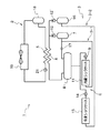
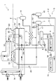
図に対応して、本発明によるヒートポンプの実施の形態は、一次循環系と二次循環系とに複合熱利用系が構成されている。そのヒートポンプ1は、図1に示されるように、二次循環系2と一次循環系3とから構成されている。両冷媒が熱的に交叉する熱交叉部分として形成されている。二次循環系2は、二次側冷媒が循環的に環流する閉じた第2循環系を形成している。一次循環系3は、一次側冷媒が循環的に環流する閉じた第2循環系を形成している。
【0019】
一次循環系3は、複合熱利用系6を形成している。その複合熱利用系は、第1一次循環系3−1と、第2一次循環系3−2とから形成されている。第1一次循環系3−1と第2一次循環系3−2とは、二次循環系2に対して並列回路として形成されている。第1一次循環系3−1は、第1一次側圧力調整部位の主要素を形成する一次側第1圧縮部位7と、一次側熱交換部分4と、液相貯留槽(受液器)8と、一次側第1膨張部位9と、第1冷却対象部位11とを含む第1直列系を形成している。第2一次循環系3−2は、第2一次側圧力調整部位の主要素を形成する一次側第2圧縮部位16と、既述の一次側熱交換部分4と、既述の液相貯留槽8と、一次側第2膨張部位14と、第2冷却対象部位15とを含む第2直列系を形成している。一次側第1圧縮部位7と一次側熱交換部分4との間に逆止弁12が介設されている。一次側第2圧縮部位16と一次側熱交換部分4との間に逆止弁12’が介設されている。液相貯留槽8と一次側第1圧縮部位7との間に、絞り17が介設されている。二次循環系2は、二次側圧力調整部位の主要素を形成する二次側圧縮部位18と、凝縮器19と、二次側膨張部位21と、二次側熱交換部分5とを含む第3直列系を形成している。
【0020】
一次側熱交換部分4と二次側熱交換部分5とは温度差ΔTを形成し、一次側熱交換部分4の温度T1は二次側熱交換部分5の温度T2より高い。その温度差ΔTは、熱的に相互作用する両循環系の両側圧力調整部位の相関的圧力制御により制御される。一次側第1圧縮部位7で圧縮されて高温化する一次側第1分流冷媒が持つ熱エネルギーの一部は、一次側熱交換部分4で二次側熱交換部分5に与えられる(汲み上げられる)。その熱エネルギーを奪われた一次側第1分流冷媒は、液相貯留槽8の中に液層状態で貯留される。その一次側第1分流冷媒は、一次側第1膨張部位9で、急激に膨張してその圧力と温度が低下し、第1冷却対象部位11に圧送される。第1冷却対象部位11として、冷蔵ショーケースが好適に例示される。利用側熱交換器を形成する第1冷却対象部位11の中では、一次側第1分流気化冷媒は、冷蔵ショーケースの中の空気又は陳列商品(例示:牛乳)から熱エネルギーを奪う。奪った熱エネルギーにより、一次側第1分流冷媒は気化し、一次側第1圧縮部位7まで輸送される。一次側第1圧縮部位7は、その気化冷媒の圧力を上昇させる。
【0021】
一次側第2圧縮部位16で圧縮されて高温化する一次側第2分流冷媒が持つ熱エネルギーの一部は、一次側熱交換部分4で二次側熱交換部分5に与えられる。その熱エネルギーを奪われた一次側第2分流液化冷媒は、液相貯留槽8の中で液層状態で貯留される。その一次側第2分流液化冷媒は、一次側第2膨張部位14で、急激に膨張してその圧力と温度が急速に低下し、第2冷却対象部位15に圧送される。第2冷却対象部位15として、冷凍ショーケースが好適に例示される。利用側熱交換器を形成する第2冷却対象部位15の中では、一次側第2分流気液混合冷媒は、冷凍ショーケースの中の空気又は陳列商品(例示:冷凍食品)から熱エネルギーを奪う。奪った熱エネルギーにより、一次側第2分流冷媒は気化して一次側第2圧縮部位16まで輸送される。一次側第2圧縮部位16は、気化冷媒の圧力を上昇させる。
【0022】
二次側圧縮部位18で圧縮されて高温化する二次側冷媒は、凝縮器19で凝縮され液化され、二次側膨張部位21で急激に膨張して、その圧力と温度が低下し、二次側熱交換部分5に圧送される。二次側熱交換部分5の中で、二次側冷媒気化し、一次側熱交換部分4から既述の熱エネルギーを奪い取る(汲み取る。)。このように奪い取った熱エネルギーは、凝縮器19で第2系外に放出される。一次系冷媒として、炭酸ガスが好適に用いられ得る。二次側冷媒として、HFC系冷媒が用いられ得る。両冷媒の使用は、ヒートポンプ1に現れる2つの異なる温度差の制御を円滑化し、その制御のためのエネルギーを最小化することができる。
【0023】
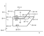
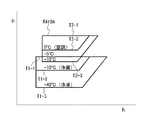
図2は、一次系と二次系のそれぞれの熱サイクルを示す圧力−エンタルピーの関係を示している。圧力は縦軸にpで表され、エンタルピーは横軸にhで表されている。一次側p−h閉曲線22は、一次側第1p−h閉曲線22−1と一次側第2p−h閉曲線22−2とから形成されている。一次側p−h閉曲線22は、温度的に二次側p−h閉曲線23に交叉する。一次側第1p−h閉曲線22−1と一次側第2p−h閉曲線22−2は、実施の既述の形態の一次側の2系統に対応している。
【0024】
一次側第1p−h閉曲線22−1は、圧力が概ね一定に維持されエンタルピーが連続的に減少する一次側第1部分22−1−1と、エンタルピーが概ね一定に維持され圧力が連続的に減少する一次側第2部分22−1−2と、圧力が概ね一定に維持されエンタルピーが連続的に増大する一次側第3部分22−1−3と、エンタルピーが連続的に増大し且つ圧力が連続的に増大する一次側第4部分22−1−4とから形成されている。
【0025】
一次側第2p−h閉曲線22−2は、圧力が概ね一定に維持されエンタルピーが連続的に減少する一次側第1部分22−2−1と、エンタルピーが概ね一定に維持され圧力が連続的に減少する一次側第2部分22−2−2と、圧力が概ね一定に維持されエンタルピーが連続的に増大する一次側第3部分22−2−3と、エンタルピーが連続的に増大し且つ圧力が連続的に増大する一次側第4部分22−2−4とから形成されている。
【0026】
二次側第1p−h閉曲線23−1は、圧力が概ね一定に維持されエンタルピーが連続的に減少する二次側第1部分23−1−1と、エンタルピーが概ね一定に維持され圧力が連続的に減少する二次側第2部分23−1−2と、圧力が概ね一定に維持されエンタルピーが連続的に増大する二次側第3部分23−1−3と、エンタルピーが連続的に増大し且つ圧力が連続的に増大する二次側第4部分23−1−4とから形成されている。
【0027】
p−h閉曲線の各部分に対応して、図中に記載される実施例温度が実現される。特には、熱交換部分で熱的に交叉する両冷媒の温度は、一次側熱交換部分4の側でT1で示され、二次側熱交換部分5の側でT2で示され、T1は実施例として−5゜Cであり、T2は実施例として−10゜Cである。この場合に温度落差(T1−T2)は5゜Cであるが、温度落差(T1−T2)が3゜C〜5゜Cの範囲に制御されて最大ヒートポンプ効率が得られる。
【0028】
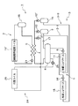
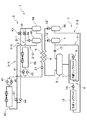
図3は、本発明によるヒートポンプの実施の他の形態を示している。実施の本形態の一次循環系3は、実施の既述の形態の一次循環系3に部分的に同じであるが、冷房用循環系24が追加されている。実施の本形態の二次循環系2は、実施の既述の形態の二次循環系2の凝縮器19が暖房用凝縮器19’に置換されている点を除いて、実施の既述の形態の二次循環系2に同じである。冷房用循環系24は、液相貯留槽8と、ポンプ25と、冷房用熱交換器26と、逆止弁27と、既述の一次側熱交換部分4とを含む直列系を形成している。冷房用循環系24は、二次循環系2に対して熱的に交叉する。二次循環系2と冷房用循環系24との間で、冷房のための熱交換が行われる。第1冷却対象部位11と第2冷却対象部位15とが外部環境から奪う熱エネルギーは、二次側熱交換部分5で二次循環系2に伝達されて、暖房用凝縮器19’で消費される。冷房用熱交換器26が室内から奪う熱エネルギーは、二次側熱交換部分5で二次循環系2に伝達されて、暖房用凝縮器19’で消費される。夏季には暖房用凝縮器19’の暖房作用が停止するが、そのエネルギーは給湯に利用され、又は、大気中に放出される。夏季には冷房用熱交換器26の冷房作用が動作し、冬季には暖房用凝縮器19’の暖房作用が動作し、冷房用熱交換器26の冷房作用が停止することは好ましい。
【0029】
図4と図5は、実施の図3の形態の冷暖房用空調を実施するためのダンパーの切換えを示している。図4は冷房動作状態を示し、図5は暖房動作状態を示す。冷房時には、図4に示されるように、空気流路に設けられる第1仕切28と第2仕切29と第3仕切31とが開放され、第4仕切32と第5仕切33とが閉鎖される。このような開放と閉鎖とにより、暖房用凝縮器19’を通る第1流路34が第1ファン35により積極的に形成される。第1流路34の流路風は、暖房用凝縮器19’で暖められて、室外に放出される。又は、その暖風の熱は給湯のために利用され得る。同時的に第2ファン36により第2流路37が積極的に形成される。第2流路37の流路風は、冷房用熱交換器26で冷却されて室内に送り込まれる。
【0030】
暖房時には、図5に示されるように、第1仕切28と第2仕切29と第3仕切31とが閉鎖され、第4仕切32と第5仕切33とが開放される。このような開放と閉鎖とにより、暖房用凝縮器19’を通る第3流路38が第1ファン35により積極的に形成される。第3流路38の流路風は、暖房用凝縮器19’で暖められて、室内に送り込まれる。
【0031】
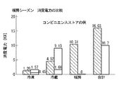
図6と図7は、実施の図3の形態について下記の仕様のコンビニエンスストアに対して高温側冷媒にR410Aを使用し、低温側冷媒に炭酸ガスを使用したときの消費電力が計算され、その計算値が従来技術の数値と比較される。
冷凍負荷=1.57KW、冷蔵負荷=16.5KW
冷房負荷=14.0KW、暖房負荷=24KW
【0032】
図6に示されるように、冷房シーズンでは、従来技術で冷凍用の消費電力が1.94KWであり、本実施例で冷凍用の消費電力は、一次側第1圧縮部位7の消費電力の0.65KWと二次側圧縮部位18の冷凍用の消費電力の0.92KWとを合計して、1.57KWである。従来技術の冷蔵用の消費電力が8.14KWであり、本実施例の形態の冷蔵用の消費電力は、一次側第1圧縮部位7の消費電力の1.66KWと二次側圧縮部位18の冷蔵用の消費電力の7.43KWとを合計して、9.09KWである。従来技術の冷房用の消費電力が5.16KWであり、本実施例の冷房用の消費電力は、ポンプ25の消費電力の0.26KWと二次側圧縮部位18の冷房用の消費電力の5.8KWとを合計して、6.06KWである。冷凍、冷蔵、冷房の合計の消費電力は、従来技術では15.24KWであり、本実施例では16.72KWである。
【0033】
図7に示されるように、暖房シーズンでは、従来技術の冷凍用の消費電力が1.20KWであり、本実施例の冷凍用の消費電力が冷房シーズンと同じく1.57KWである。また、従来方式において冷蔵用の消費電力が4.52KWであり、本実施例の冷蔵用の消費電力は、一次側第1圧縮部位7の消費電力の1.66KWと二次側圧縮部位18の冷蔵用の消費電力の7.47KWとを合計して、9.13KWである。従来技術の暖房用の消費電力が10.31KWであり、本実施例の暖房用の消費電力が0KWである。冷凍、冷蔵、暖房の合計の消費電力は、従来技術では16.03KWであり、本実施例では10.7KWである。
【0034】
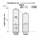
図8は、既述のコンビニエンスストアの例で、本実施例と従来技術の年間の消費電力量を比較して示している。冷房シーズンの運転時間は2000時間であり、暖房シーズンの運転時間は4000時間である。従来の個別の冷凍装置では、冷房シーズンの電力消費量は30.5×(10の3乗)KWhであり、冷暖房シーズンの合計の電力消費量は94.6×(10の3乗)KWhであり、本実施例では、冷房シーズンの電力消費量は33.4×(10の3乗)KWhであり、冷暖房シーズンの合計の電力消費量は76.2×(10の3乗)KWhである。この試算では、20%程度の省エネルギー化が実現している。
【0035】
本実施例では、高温側にHFC系冷媒を、低温側に炭酸ガス冷媒を使用することによりオゾン層を破壊せず、毒性、爆発性、可燃性がなく、安全であり、HFC系冷媒充填量を少なくすることができて、地球温暖化の影響が少ないカスケード式冷凍装置を提供することができる。
【0036】
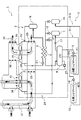
図9は、本発明によるヒートポンプの実施の更に他の形態を示している。実施の本形態の一次循環系3は、実施の図1の形態の一次循環系3に同じである。実施の本形態の二次循環系2が二次側熱交換部分5と二次側圧縮部位18と凝縮器19と二次側膨張部位21とから形成される点は、実施の図1の形態のその構成に同じである。実施の本形態の二次循環系2は、以下に、第1二次循環系2−1と呼ばれる。実施の本形態では、第1二次循環系2−1に並列に第2二次循環系2−2が追加され、更に、第3二次循環系2−3が追加される。第1二次循環系2−1では、二次側圧縮部位18と凝縮器19との間に、開閉弁39が介設され、更に、凝縮器19と二次側膨張部位21との間で第1二次循環系2−1に、追加逆止弁41と追加膨張弁42とが介設される。追加逆止弁41と追加膨張弁42は、並列に接続されている。
【0037】
第2二次循環系2−2は、二次側熱交換部分5と二次側圧縮部位18と、開閉弁43と、逆止弁44と、冷房暖房切換熱交換器45と、追加逆止弁46と、既述の二次側膨張部位21とから形成されている。
【0038】
追加二次側圧縮部位48が追加される。追加二次側圧縮部位48と凝縮器19との間に、追加逆止弁49が介設される。追加二次側圧縮部位48と冷房暖房切換熱交換器45との間に、開閉弁51が介設される。第3二次循環系2−3は、追加二次側圧縮部位48と、逆止弁49と、凝縮器19と、追加逆止弁41と、追加膨張弁47と、冷房暖房切換熱交換器45と、開閉弁51とを含む循環直列系を形成している。追加逆止弁46と追加膨張弁47とは、並列に介設されている。
【0039】
第1二次循環系2−1は、基本的熱サイクルを形成している。第2二次循環系2−2では、二次側圧縮部位18から送り出される二次側分流冷媒は開状態の開閉弁43を通過し、逆止弁44を通過して、冷房暖房切換熱交換器45で暖房的熱交換を受け、追加逆止弁46を通り、二次側膨張部位21で膨張して急冷されて、二次側熱交換部分5で一次側の熱エネルギーを奪って、二次側圧縮部位18に還流する。このような暖房時には、開閉弁51は閉鎖される。第2二次循環系2−2は、二次側熱交換部分5で一次循環系から奪った熱エネルギーを熱源とするヒートポンプを構成している。第3二次循環系2−3では、追加二次側圧縮部位48から送り出される二次側分流冷媒は逆止弁49を通過し、凝縮器19で凝縮され、追加逆止弁41を通過し、追加膨張弁47で膨張して急冷され、冷房暖房切換熱交換器45で冷房的熱交換を受け、開状態の開閉弁51を通過して、追加二次側圧縮部位48に還流する。このような冷房時には、開閉弁43は閉鎖される。第2二次循環系2−2と第3二次循環系2−3の循環が停止される場合には、実施の本形態は、実施の図1の形態に一致する。
【0040】
図10は、実施の図9の形態の圧力−エンタルピー線図を示している。各部位の制御目標温度は、下記の通りである。
T1−1=−5゜C,T1−2=−10゜C,T1−3=−40゜C
T2−1=50゜C,T2−2=0゜C,T2−3=−10゜C
両系間の熱交換は、温度落差ΔTに対応して行われる。
ΔT=[T1−1]−[T2−3]=(−5゜C)−(−10゜C)=5゜C
ΔTは、既述の通り、3゜C〜5゜Cが適正である。ΔTがこのような範囲にあれば、ヒートポンプのエネルギー消費量を最小化することができるT1−1が存在する。
【0041】
一次側の2様の圧力−エンタルピー線図により、冷蔵と冷凍が実行される。一次側の一次側熱交換部分4の温度は2様の圧力−エンタルピー線図で同じである。一次側の冷凍と冷蔵では、第1二次循環系2−1と一次循環系3の熱的交叉が行われる。第2二次循環系2−2と一次循環系3の熱的交叉により、冷房暖房切換熱交換器45で暖房が実行される。暖房時には、第1冷却対象部位11と第2冷却対象部位15で得る熱エネルギーは、二次側に供給される。この場合には、二次側熱交換部分5の温度は、T2−3の−10゜Cに制御される。冷房の空調時には、熱交換器45は0゜Cに制御される。冷房時には、一次側第1圧縮部位7と一次側第2圧縮部位16の駆動エネルギー、及び、二次側圧縮部位18と追加二次側圧縮部位48の駆動エネルギーが最小になるように、T1−1とT2−3とを制御的に設定することができる。第1冷却対象部位11と第2冷却対象部位15で得る熱ネルギーは二次系に供給され、第1二次循環系2−1の凝縮器で放熱され給湯用の熱エネルギーとして利用され得るヒートポンプが実現している。
【0042】
このように、一次系と二次系がより複雑である系として構成され、より最適な圧力制御による熱交叉部位の熱交換態様が切り換えられて、エネルギー節約動作が多様に効果的に実現する。
【0043】
【発明の効果】
本発明のヒートポンプは、一次系と二次系の間のダイナミックなヒートポンプ作用による熱交換が実現され、結果的に、消費電力の削減を実現することができる。
【図面の簡単な説明】
【図1】図1は、本発明のヒートポンプによる実施の形態を示す回路図である。
【図2】図2は、p−h線図を示すグラフである。
【図3】図3は、本発明によるヒートポンプの実施の他の形態を示す回路図である。
【図4】図4は、流路の切換を示す回路図である。
【図5】図5は、流路の他の切換を示す回路図である。
【図6】図6は、実施例の消費電力を示すグラフである。
【図7】図7は、実施例の他の消費電力を示すグラフである。
【図8】図8は、実施例の消費電力比較を示すグラフである。
【図9】図9は、本発明によるヒートポンプの実施の更に他の形態を示すグラフである。
【図10】図10は、更に他のp−h線図を示すグラフである。
【符号の説明】
1…熱交換部分
2…二次循環系
2−1…第1二次循環系
2−2…第2二次循環系
2−3…二次側付随的循環系
3…一次循環系
3−1…第1一次循環系
3−2…第2一次循環系
4…一次側熱交換部分
5…二次側熱交換部分
7…一次側圧力調整部位
8…受液器
9…第1一次側膨張弁
11…冷蔵対象部位
14…第2一次側膨張弁
15…冷凍対象部位
16…第2一次側圧力調整部位
18…二次側圧力調整部位
19…第1熱交換器(凝縮器)
21…(二次側)膨張弁
22−1…一次側第1圧力−エンタルピー関係
22−2…一次側第2圧力−エンタルピー関係
23…二次側圧力−エンタルピー関係
23−1…二次側第1圧力−エンタルピー関係
23−2…二次側第2圧力−エンタルピー関係
24…冷房系
25…ポンプ
26…冷房用熱交換器
27…逆止弁
39…第1開閉弁
41…第1逆止弁
42…他の膨張弁
43…第2開閉弁
44…第2逆止弁
45…第2熱交換器
46…第3逆止弁
49…第4逆止弁
47…他の膨張弁
48…二次側付属的圧力調整部位
51…第3開閉弁[0001]
BACKGROUND OF THE INVENTION
The present invention relates to a heat pump, and more particularly to a heat pump in which freezing, refrigeration, and air conditioning are performed simultaneously in a complex heat control space such as a convenience store, a supermarket, and a food factory.
[0002]
[Prior art]
A heat exchanger is used for temperature control such as cooling, heating, and freezing. If a single type of refrigerant is used for the heat exchanger, it may not be possible to satisfy both safety and environmental properties at the same time. A technique for satisfying both of these properties at the same time is known from
[0003]
In complex heat control spaces such as convenience stores, supermarkets, and food factories, at least two of the three types of heat control, refrigeration, refrigeration, and cooling, are executed. In such a thermal control space, power reduction is required in addition to the satisfaction of both properties described above.
[0004]
Reduction of electric power for combined heat control is required.
[0005]
[Patent Document 1]
Japanese Patent Laid-Open No. 10-306952
[Patent Document 2]
JP 2001-91074 A
[0006]
[Problems to be solved by the invention]
The subject of this invention is providing the heat pump which reduces the electric power of composite heat control.
[0007]
[Means for Solving the Problems]
Means for solving the problem is expressed as follows. Technical matters appearing in the expression are appended with numbers, symbols, etc. in parentheses. The numbers, symbols, and the like are technical matters constituting at least one embodiment or a plurality of embodiments of the present invention or a plurality of embodiments, in particular, the embodiments or examples. This corresponds to the reference numbers, reference symbols, and the like attached to the technical matters expressed in the drawings corresponding to. Such reference numbers and reference symbols clarify the correspondence and bridging between the technical matters described in the claims and the technical matters of the embodiments or examples. Such correspondence or bridging does not mean that the technical matters described in the claims are interpreted as being limited to the technical matters of the embodiments or examples.
[0008]
The heat pump according to the present invention includes a primary circulation system (3) and a secondary circulation system (2). The primary circulation system (3) is configured to control the temperature of the primary side heat exchange part (4) by controlling the pressure in the primary side heat exchange part (4) and the primary side heat exchange part (4). And a pressure adjusting portion. The secondary circulation system (2) controls the temperature of the secondary heat exchange part (5) by controlling the pressure in the secondary heat exchange part (5) and the secondary heat exchange part (5). The secondary pressure adjusting part (18) to be controlled is formed. The primary side heat exchange part (4) gives the secondary circulation system (2) the energy that the primary circulation system (3) draws from the outside through the secondary side heat exchange part (5). The primary side circulation system (3) is composed of a first primary circulation system (3-1) and a second primary circulation system (3-2). The first primary circulation system (3-1) and the second primary circulation system (3-2) have a parallel relationship with the secondary circulation system (2). The secondary circulation system (2) has a secondary pressure-enthalpy relationship. The first primary circulation system (3-1) has a primary side first pressure-enthalpy relationship, and the second primary circulation system (3-2) has a primary side second pressure-enthalpy relationship. The first temperature T1 of the primary side heat exchange part (4) is higher than the second temperature T2 of the secondary side heat exchange part (5). In such a heat pump, the aforementioned energy corresponds to the temperature difference (T1-T2).
[0009]
In a complex system in which the primary side constitutes two parallel circulation systems, the heat energy absorbed by the two primary systems is pumped up to the secondary circulation system in a complex manner, maximizing the amount of recovered heat and maximizing the recovery efficiency. Can be realized.
[0010]
The two primary circulation systems (3-1, 2) are connected in parallel to the secondary circulation system (2), and the two primary circulation systems (3-1, 2) are common primary heat exchange portions (4). Thermal energy that is crossed thermally in common with the secondary heat exchange part (5) of the secondary circulation system (2) and absorbed by the first primary circulation system (3-1) and the second primary circulation system (3- The heat pump efficiency at which the heat energy absorbed by 2) is pumped to the secondary circulation system (2) is maximized by the control by the primary pressure adjustment part (7, 16) and the secondary pressure adjustment part (18). It becomes. If the primary pressure adjustment region is controlled by the first primary pressure adjustment region (7) and the second primary pressure adjustment region (16), the pumping energy by the heat pump is further maximized.
[0011]
Such a heat pump action can dynamically control the refrigeration function of the first primary circulation system (3-1) and the refrigeration function of the second primary circulation system (3-2). In this case, since the secondary circulation system (2) has an air conditioning function, the utilization efficiency of the recovered heat is increased.
[0012]
The secondary circulation system (2) is formed by a first secondary circulation system (2-1) and a second secondary circulation system (2-2). The first secondary circulation system (2-1) has a secondary side first pressure-enthalpy relationship (23-1), and the second secondary circulation system has a secondary side second pressure-enthalpy relationship (23- 2). Also in this case, it is particularly preferable to parallelize the secondary pressure adjusting portions (18, 48) in terms of improving the heat exchange rate and maximizing the recovered heat energy. In this case, the first secondary circulation system (2-1) has a heating function or a hot water supply function, and the second secondary circulation system (2-2) has a heating function or a hot water supply function. The secondary side can have various heat utilization functions that use the heat sucked up from the primary side as a heat source, and it is possible to minimize energy consumption in parallel multi-systems, especially double-sided parallel multi-systems (minimum value always exists) To do).
[0013]
As described above, it is particularly preferable that the primary pressure adjustment part is composed of the first primary pressure adjustment part (7) and the second primary pressure adjustment part (16). The first primary circulation system (3-1) includes a first primary pressure adjusting part (7), a primary heat exchange part (4), a liquid receiver (8), and a first primary expansion valve (9). And a series system including the refrigeration target part (11). The second primary circulation system (3-2) includes a second primary pressure adjusting part (16), a primary heat exchange part (4), a liquid receiver (8), and a second primary expansion valve (14). And a series system including the part to be frozen (15).
[0014]
A cooling system (24) may be further configured. The cooling system (24) is located in the liquid receiver (8), the pump (25) positioned forward in the refrigerant circulation direction of the liquid receiver (8), and forward in the refrigerant circulation direction of the pump (25). The cooling heat exchanger (26), the check valve (27) positioned forward in the refrigerant circulation direction of the cooling heat exchanger (26), and positioned forward in the refrigerant circulation direction of the check valve (27). A series system including the primary heat exchange part (4) is formed. The addition of such a cooling system does not hinder the proper maintenance of the heat utilization efficiency by controlling the above-described pressure adjustment part.
[0015]
The secondary circulation system (2) is a series including a secondary pressure adjusting part (18), a condenser (19), a secondary expansion valve (21), and a secondary heat exchange part (5). Form a system. In this case, the condenser (19) is used as a heating condenser.
[0016]
The first secondary circulation system (2-1) includes a secondary side pressure adjustment part (18), a first on-off valve (39), a first heat exchanger (19), and a first check valve (41). ), An expansion valve (21), and a secondary heat exchange part (5). The second secondary circulation system (2-2) includes a secondary pressure adjusting portion (18), a second on-off valve (43), a second check valve (44), and a second heat exchanger (45 ), A third check valve (46), an expansion valve (21), and a secondary heat exchange portion (5).
[0017]
The secondary circulation system (2) forms a secondary side accessory circulation system (2-3). The secondary side auxiliary circulation system (2-3) includes a secondary side auxiliary pressure adjusting portion (48), a fourth check valve (49), a first heat exchanger (19), and a first reverse valve. A third series system including a stop valve (41), another expansion valve (47), a second heat exchanger (45), and a third on-off valve (51) is formed. The third check valve (46) and the other expansion valve (47), or the first check valve (41) and the other expansion valve (42) are connected in parallel.
[0018]
DETAILED DESCRIPTION OF THE INVENTION
Corresponding to the figure, in the embodiment of the heat pump according to the present invention, a combined heat utilization system is configured in the primary circulation system and the secondary circulation system. As shown in FIG. 1, the
[0019]
The
[0020]
The primary side
[0021]
A part of the thermal energy of the primary second shunt refrigerant that is compressed at the primary
[0022]
The secondary side refrigerant compressed at the secondary
[0023]
FIG. 2 shows the pressure-enthalpy relationship showing the thermal cycles of the primary system and the secondary system. The pressure is represented by p on the vertical axis and the enthalpy is represented by h on the horizontal axis. The primary side ph closed curve 22 is formed by a primary side first ph closed curve 22-1 and a primary side second ph closed curve 22-2. The primary side ph closed curve 22 crosses the secondary side ph closed curve 23 in terms of temperature. The primary side first ph closed curve 22-1 and the primary side second ph closed curve 22-2 correspond to the two systems on the primary side described in the embodiments.
[0024]
The primary side first ph closed curve 22-1 includes a primary side first portion 22-1-1 in which the pressure is maintained approximately constant and the enthalpy continuously decreases, and the enthalpy is maintained approximately constant and the pressure is continuously increased. The primary side second portion 22-1-2 that decreases, the primary side third portion 22-1-3 in which the pressure is maintained substantially constant and the enthalpy continuously increases, and the enthalpy continuously increases and the pressure increases. It is formed from a primary side fourth portion 22-1-4 that continuously increases.
[0025]
The primary side second ph closed curve 22-2 includes a primary side first portion 22-2-1 in which the pressure is maintained approximately constant and the enthalpy continuously decreases, and the enthalpy is maintained approximately constant and the pressure is continuously increased. The primary side second portion 22-2-2 that decreases, the primary side third portion 22-2-3 that maintains the pressure approximately constant and the enthalpy continuously increases, and the enthalpy continuously increases and the pressure increases. It is formed from a primary side fourth portion 22-2-4 that continuously increases.
[0026]
The secondary side first ph closed curve 23-1 is the secondary side first portion 23-1-1 in which the pressure is maintained substantially constant and the enthalpy continuously decreases, and the enthalpy is maintained approximately constant and the pressure is continuous. Secondary side portion 23-1-2 that gradually decreases, secondary side third portion 23-1-3 whose pressure is maintained substantially constant and enthalpy continuously increases, and enthalpy continuously increases And a secondary side fourth portion 23-1-4 in which the pressure continuously increases.
[0027]
Corresponding to each part of the ph closed curve, the example temperatures described in the figure are realized. In particular, the temperature of both refrigerants that are thermally crossed in the heat exchange portion is indicated by T1 on the primary
[0028]
FIG. 3 shows another embodiment of the heat pump according to the present invention. Although the primary
[0029]
4 and 5 show the switching of the damper for implementing the air conditioning for heating and cooling according to the embodiment shown in FIG. FIG. 4 shows the cooling operation state, and FIG. 5 shows the heating operation state. During cooling, the
[0030]
At the time of heating, as shown in FIG. 5, the
[0031]
FIG. 6 and FIG. 7 show the power consumption when R410A is used as the high-temperature side refrigerant and carbon dioxide gas is used as the low-temperature side refrigerant for the convenience store having the following specifications for the embodiment of FIG. The calculated value is compared with the prior art figures.
Refrigeration load = 1.57 kW, refrigeration load = 16.5 kW
Cooling load = 14.0KW, heating load = 24KW
[0032]
As shown in FIG. 6, in the cooling season, the power consumption for refrigeration is 1.94 KW in the prior art, and the power consumption for refrigeration in this embodiment is 0% of the power consumption of the primary
[0033]
As shown in FIG. 7, in the heating season, the power consumption for refrigeration in the prior art is 1.20 KW, and the power consumption for refrigeration in the present embodiment is 1.57 KW as in the cooling season. In the conventional method, the power consumption for refrigeration is 4.52 KW, and the power consumption for refrigeration in this embodiment is 1.66 KW of the power consumption of the primary side
[0034]
FIG. 8 is an example of the convenience store described above, and shows a comparison of the annual power consumption of this embodiment and the prior art. The operation time in the cooling season is 2000 hours, and the operation time in the heating season is 4000 hours. In the conventional individual refrigeration system, the power consumption in the cooling season is 30.5 × (10 3) KWh, and the total power consumption in the air conditioning season is 94.6 × (10 3) KWh. Yes, in this embodiment, the power consumption in the cooling season is 33.4 × (10 3) KWh, and the total power consumption in the air conditioning season is 76.2 × (10 3) KWh. . In this trial calculation, energy saving of about 20% has been realized.
[0035]
In this embodiment, by using an HFC refrigerant on the high temperature side and a carbon dioxide refrigerant on the low temperature side, the ozone layer is not destroyed, there is no toxicity, no explosiveness, no flammability, and the HFC refrigerant filling amount is safe. Can be reduced, and a cascade refrigeration apparatus with less influence of global warming can be provided.
[0036]
FIG. 9 shows still another embodiment of the heat pump according to the present invention. The
[0037]
The second secondary circulation system 2-2 includes a secondary
[0038]
An additional
[0039]
The first secondary circulation system 2-1 forms a basic thermal cycle. In the second secondary circulation system 2-2, the secondary side diverted refrigerant sent out from the secondary
[0040]
FIG. 10 shows a pressure-enthalpy diagram of the embodiment of FIG. The control target temperature of each part is as follows.
T1-1 = -5 ° C, T1-2 = -10 ° C, T1-3 = -40 ° C
T2-1 = 50 ° C, T2-2 = 0 ° C, T2-3 = -10 ° C
Heat exchange between the two systems is performed corresponding to the temperature drop ΔT.
ΔT = [T1-1] − [T2-3] = (− 5 ° C.) − (− 10 ° C.) = 5 ° C.
As described above, 3 ° C to 5 ° C is appropriate for ΔT. If ΔT is in such a range, there is T1-1 that can minimize the energy consumption of the heat pump.
[0041]
Refrigeration and freezing are performed according to two pressure-enthalpy diagrams on the primary side. The temperature of the primary side
[0042]
In this way, the primary system and the secondary system are configured as more complicated systems, and the heat exchange mode of the heat cross-over portion by more optimal pressure control is switched, thereby realizing various energy saving operations effectively.
[0043]
【The invention's effect】
In the heat pump of the present invention, heat exchange by a dynamic heat pump action between the primary system and the secondary system is realized, and as a result, power consumption can be reduced.
[Brief description of the drawings]
FIG. 1 is a circuit diagram showing an embodiment of a heat pump according to the present invention.
FIG. 2 is a graph showing a ph diagram.
FIG. 3 is a circuit diagram showing another embodiment of the heat pump according to the present invention.
FIG. 4 is a circuit diagram showing channel switching.
FIG. 5 is a circuit diagram showing another switching of the flow path.
FIG. 6 is a graph illustrating power consumption in the example.
FIG. 7 is a graph showing another power consumption of the example.
FIG. 8 is a graph showing a power consumption comparison of examples.
FIG. 9 is a graph showing still another embodiment of the heat pump according to the present invention.
FIG. 10 is a graph showing still another ph diagram.
[Explanation of symbols]
1 ... Heat exchange part
2 ... Secondary circulation system
2-1. First secondary circulation system
2-2. Second secondary circulation system
2-3 ... Secondary side circulatory system
3 ... Primary circulation system
3-1. First primary circulation system
3-2 ... Second primary circulation system
4 ... Primary heat exchange part
5 ... Secondary heat exchange part
7 ... Primary pressure adjustment part
8 ... Receiver
9 ... 1st primary side expansion valve
11 ... refrigeration target part
14 ... Second primary side expansion valve
15 ... Freezing object
16: Second primary pressure adjustment part
18 ... Secondary pressure adjustment part
19 ... 1st heat exchanger (condenser)
21 ... (secondary side) expansion valve
22-1 ... Primary side first pressure-enthalpy relationship
22-2: Primary side second pressure-enthalpy relationship
23 ... Secondary pressure-enthalpy relationship
23-1 ... Secondary side first pressure-enthalpy relationship
23-2 ... Secondary second pressure-enthalpy relationship
24 ... Cooling system
25 ... Pump
26 ... Heat exchanger for cooling
27. Check valve
39. First on-off valve
41. First check valve
42. Other expansion valve
43 ... Second on-off valve
44. Second check valve
45 ... Second heat exchanger
46 ... Third check valve
49 ... Fourth check valve
47. Other expansion valve
48 ... Secondary side pressure adjustment part
51. Third on-off valve
Claims (10)
二次循環系とを構成し、
前記一次循環系は、
一次側熱交換部分と、
前記一次側熱交換部分の中の圧力を制御することにより前記一次側熱交換部分の温度を制御する一次側圧力調整部分とを形成し、
前記二次循環系は、
二次側熱交換部分と、
前記二次側熱交換部分の中の圧力を制御することにより前記二次側熱交換部分の温度を制御する二次側圧力調整部分とを形成し、
前記一次側熱交換部分は前記一次循環系が外界から汲み取るエネルギーを前記二次側熱交換部分を介して前記二次循環系に与え、
前記一次循環系は、
第1一次循環系と、
第2一次循環系とを構成し、
前記第1一次循環系と前記第2一次循環系は前記二次循環系に対して並列関係を有し、
前記二次循環系は二次側圧力−エンタルピー関係を有し、前記第1一次循環系は一次側第1圧力−エンタルピー関係を有し、前記第2一次循環系は一次側第2圧力−エンタルピー関係を有し、且つ、前記一次側熱交換部分の第1温度T1は前記二次側熱交換部分の第2温度T2より高く、前記エネルギーは温度差(T1−T2)に対応する
ヒートポンプ。The primary circulatory system,
A secondary circulation system,
The primary circulation system is
A primary heat exchange part;
Forming a primary pressure adjusting part for controlling the temperature of the primary heat exchange part by controlling the pressure in the primary heat exchange part,
The secondary circulation system is
A secondary heat exchange part;
Forming a secondary pressure adjusting portion for controlling the temperature of the secondary heat exchange portion by controlling the pressure in the secondary heat exchange portion;
The primary side heat exchange part gives the secondary circulation system energy that the primary circulation system draws from the outside through the secondary side heat exchange part,
The primary circulation system is
A first primary circulatory system;
A second primary circulation system,
The first primary circulation system and the second primary circulation system have a parallel relationship with the secondary circulation system;
The secondary circulation system has a secondary pressure-enthalpy relationship, the first primary circulation system has a primary first pressure-enthalpy relationship, and the second primary circulation system has a primary second pressure-enthalpy relationship. The first temperature T1 of the primary heat exchange part is higher than the second temperature T2 of the secondary heat exchange part, and the energy corresponds to a temperature difference (T1-T2).
請求項1のヒートポンプ。The heat pump according to claim 1, wherein the first primary circulation system has a refrigeration function, and the second primary circulation system has a refrigeration function.
請求項1のヒートポンプ。The heat pump according to claim 1, wherein the secondary circulation system has an air conditioning function.
第1二次循環系と、
第2二次循環系とを形成し、前記第2二次循環系は前記第1二次循環系に対して並列関係を有し、
前記第1二次循環系は、二次側第1圧力−エンタルピー関係を有し、
前記第2二次循環系は、二次側第2圧力−エンタルピー関係を有する
請求項1のヒートポンプ。The secondary circulation system is
A first secondary circulatory system;
A second secondary circulation system, wherein the second secondary circulation system has a parallel relationship with the first secondary circulation system;
The first secondary circulation system has a secondary side first pressure-enthalpy relationship,
The heat pump according to claim 1, wherein the second secondary circulation system has a secondary side second pressure-enthalpy relationship.
請求項4のヒートポンプ。The heat pump according to claim 4, wherein the first secondary circulation system has a heating function, and the second secondary circulation system has a hot water supply function.
第1一次側圧力調整部位と、
第2一次側圧力調整部位とを構成し、
前記第1一次循環系は、前記第1一次側圧力調整部位と前記一次側熱交換部分と、受液器と、第1一次側膨張弁と、冷蔵対象部位とを含む直列系を形成し、
前記第2一次循環系は、前記第2一次側圧力調整部位と前記一次側熱交換部分と、前記受液器と、第2一次側膨張弁と、冷凍対象部位とを含む直列系を形成し、
冷房系を更に構成し、
前記冷房系は、前記受液器と、前記受液器の冷媒循環方向に前方に位置するポンプと、前記ポンプの前記冷媒循環方向に前方に位置する冷房用熱交換器と、前記冷房用熱交換器の前記冷媒循環方向に前方に位置する逆止弁と、前記逆止弁の前記冷媒循環方向に前方に位置する前記一次側熱交換部分とを含む直列系を形成する
請求項1のヒートポンプ。The primary pressure adjustment part is:
A first primary pressure adjustment portion;
A second primary pressure adjusting portion;
The first primary circulation system forms a series system including the first primary pressure adjustment part, the primary heat exchange part, a liquid receiver, a first primary expansion valve, and a refrigeration target part,
The second primary circulation system forms a series system including the second primary pressure adjusting part, the primary heat exchange part, the liquid receiver, a second primary side expansion valve, and a part to be frozen. ,
Further configuring the cooling system,
The cooling system includes the liquid receiver, a pump positioned forward in the refrigerant circulation direction of the liquid receiver, a cooling heat exchanger positioned forward in the refrigerant circulation direction of the pump, and the cooling heat. 2. The heat pump according to claim 1, wherein the heat pump forms a series system including a check valve positioned forward in the refrigerant circulation direction of the exchanger and the primary heat exchange portion positioned forward in the refrigerant circulation direction of the check valve. .
前記凝縮器は暖房用凝縮器として用いられる
請求項6のヒートポンプ。The secondary circulation system forms a series system including the secondary side pressure adjustment part, a condenser, a secondary side expansion valve, and the secondary side heat exchange part,
The heat pump according to claim 6, wherein the condenser is used as a heating condenser.
前記第2二次循環系は、前記二次側圧力調整部位と、第2開閉弁と、第2逆止弁と、第2熱交換器と、第3逆止弁と、前記膨張弁と、前記二次側熱交換部分とを含む第1直列系を形成する
請求項4のヒートポンプ。The first secondary circulation system includes the secondary side pressure adjustment portion, a first on-off valve, a first heat exchanger, a first check valve, an expansion valve, and the secondary side heat exchange portion. Forming a second series system including
The second secondary circulation system includes the secondary pressure adjusting part, a second on-off valve, a second check valve, a second heat exchanger, a third check valve, and the expansion valve, The heat pump of Claim 4 which forms the 1st series system containing the said secondary side heat exchange part.
請求項8のヒートポンプ。The secondary circulation system forms a secondary side auxiliary circulation system, and the secondary side auxiliary circulation system includes a secondary side auxiliary pressure adjusting portion, a fourth check valve, and a first heat exchanger. , Forming a third series system including a first check valve, another expansion valve, a second heat exchanger, and a third on-off valve, and the third check valve and the other expansion valve are: Alternatively, the heat pump according to claim 8, wherein the first check valve and the other expansion valve are connected in parallel.
請求項1のヒートポンプ。The heat pump according to claim 1, wherein the primary side first pressure-enthalpy relationship and the primary side second pressure-enthalpy relationship are dynamically controlled by a thermal state of the first primary circulation system and the second primary circulation system.
Priority Applications (1)
| Application Number | Priority Date | Filing Date | Title |
|---|---|---|---|
| JP2003073447A JP4043386B2 (en) | 2002-11-08 | 2003-03-18 | heat pump |
Applications Claiming Priority (2)
| Application Number | Priority Date | Filing Date | Title |
|---|---|---|---|
| JP2002324852 | 2002-11-08 | ||
| JP2003073447A JP4043386B2 (en) | 2002-11-08 | 2003-03-18 | heat pump |
Publications (3)
| Publication Number | Publication Date |
|---|---|
| JP2004205193A true JP2004205193A (en) | 2004-07-22 |
| JP2004205193A5 JP2004205193A5 (en) | 2005-07-14 |
| JP4043386B2 JP4043386B2 (en) | 2008-02-06 |
Family
ID=32828375
Family Applications (1)
| Application Number | Title | Priority Date | Filing Date |
|---|---|---|---|
| JP2003073447A Expired - Lifetime JP4043386B2 (en) | 2002-11-08 | 2003-03-18 | heat pump |
Country Status (1)
| Country | Link |
|---|---|
| JP (1) | JP4043386B2 (en) |
Cited By (9)
| Publication number | Priority date | Publication date | Assignee | Title |
|---|---|---|---|---|
| CN100520228C (en) * | 2005-09-20 | 2009-07-29 | 三洋电机株式会社 | Freezing system |
| WO2009107828A1 (en) * | 2008-02-27 | 2009-09-03 | カルソニックカンセイ株式会社 | Waste heat regeneration system |
| JP2012107805A (en) * | 2010-11-17 | 2012-06-07 | Mitsubishi Electric Corp | Refrigerating device |
| WO2013018148A1 (en) * | 2011-08-04 | 2013-02-07 | 三菱電機株式会社 | Refrigeration device |
| JP2013510286A (en) * | 2009-11-03 | 2013-03-21 | イー・アイ・デュポン・ドウ・ヌムール・アンド・カンパニー | Cascade refrigeration system using fluoroolefin refrigerant |
| JPWO2013018148A1 (en) * | 2011-08-04 | 2015-02-23 | 三菱電機株式会社 | Refrigeration equipment |
| CN105276849A (en) * | 2014-07-01 | 2016-01-27 | 松下知识产权经营株式会社 | Refrigerating system |
| JP2018066513A (en) * | 2016-10-19 | 2018-04-26 | パナソニックIpマネジメント株式会社 | Refrigeration system and indoor unit |
| CN113566451A (en) * | 2020-04-29 | 2021-10-29 | 约克广州空调冷冻设备有限公司 | Heat pump system |
-
2003
- 2003-03-18 JP JP2003073447A patent/JP4043386B2/en not_active Expired - Lifetime
Cited By (13)
| Publication number | Priority date | Publication date | Assignee | Title |
|---|---|---|---|---|
| CN100520228C (en) * | 2005-09-20 | 2009-07-29 | 三洋电机株式会社 | Freezing system |
| WO2009107828A1 (en) * | 2008-02-27 | 2009-09-03 | カルソニックカンセイ株式会社 | Waste heat regeneration system |
| JP2013510286A (en) * | 2009-11-03 | 2013-03-21 | イー・アイ・デュポン・ドウ・ヌムール・アンド・カンパニー | Cascade refrigeration system using fluoroolefin refrigerant |
| JP2012107805A (en) * | 2010-11-17 | 2012-06-07 | Mitsubishi Electric Corp | Refrigerating device |
| JPWO2013018148A1 (en) * | 2011-08-04 | 2015-02-23 | 三菱電機株式会社 | Refrigeration equipment |
| CN103635761A (en) * | 2011-08-04 | 2014-03-12 | 三菱电机株式会社 | freezer |
| WO2013018148A1 (en) * | 2011-08-04 | 2013-02-07 | 三菱電機株式会社 | Refrigeration device |
| US9429347B2 (en) | 2011-08-04 | 2016-08-30 | Mitsubishi Electric Corporation | Refrigeration apparatus |
| CN105276849A (en) * | 2014-07-01 | 2016-01-27 | 松下知识产权经营株式会社 | Refrigerating system |
| JP2016014490A (en) * | 2014-07-01 | 2016-01-28 | パナソニックIpマネジメント株式会社 | Refrigeration system |
| JP2018066513A (en) * | 2016-10-19 | 2018-04-26 | パナソニックIpマネジメント株式会社 | Refrigeration system and indoor unit |
| CN113566451A (en) * | 2020-04-29 | 2021-10-29 | 约克广州空调冷冻设备有限公司 | Heat pump system |
| CN113566451B (en) * | 2020-04-29 | 2022-12-30 | 约克广州空调冷冻设备有限公司 | Heat pump system |
Also Published As
| Publication number | Publication date |
|---|---|
| JP4043386B2 (en) | 2008-02-06 |
Similar Documents
| Publication | Publication Date | Title |
|---|---|---|
| CA2526194C (en) | An air condition heat pump with cross-defrosting system | |
| CN203249455U (en) | air conditioner | |
| CN102235775B (en) | Heat pump type speed heating apparatus | |
| CN100419349C (en) | Refrigeration equipment | |
| JP5854751B2 (en) | Cooling system | |
| JP4298990B2 (en) | Refrigeration equipment using carbon dioxide as refrigerant | |
| JP5734424B2 (en) | Air conditioning and hot water supply complex system | |
| JP2009228979A (en) | Air conditioner | |
| JP4317793B2 (en) | Cooling system | |
| JP2018132269A (en) | Heat pump system | |
| JP4043386B2 (en) | heat pump | |
| CN109564043A (en) | Heat exchanger alternate type heat pump system | |
| JP4033788B2 (en) | Heat pump equipment | |
| GB2458901A (en) | Heat pump system with first and second compressors | |
| JP2000205774A (en) | Capsule type heat storage device | |
| JP4270803B2 (en) | Cold generation system | |
| JP2009042886A (en) | vending machine | |
| JP3821286B2 (en) | Refrigeration system combining absorption type and compression type and its operating method | |
| JP3871207B2 (en) | Refrigeration system combining absorption and compression | |
| KR100500954B1 (en) | Ice thermal storage heat pump unit | |
| JP2004156805A (en) | Heat pump system | |
| JP4100462B2 (en) | Heat utilization system | |
| KR102955459B1 (en) | Air Conditioning of Waste Heat Recovery Type Heat Pump | |
| JP2006308251A (en) | Thermal storage heat recovery device | |
| JP3874263B2 (en) | Refrigeration system combining absorption and compression |
Legal Events
| Date | Code | Title | Description |
|---|---|---|---|
| A521 | Request for written amendment filed |
Free format text: JAPANESE INTERMEDIATE CODE: A523 Effective date: 20041124 |
|
| A621 | Written request for application examination |
Free format text: JAPANESE INTERMEDIATE CODE: A621 Effective date: 20041124 |
|
| A131 | Notification of reasons for refusal |
Free format text: JAPANESE INTERMEDIATE CODE: A131 Effective date: 20070611 |
|
| A521 | Request for written amendment filed |
Free format text: JAPANESE INTERMEDIATE CODE: A523 Effective date: 20070809 |
|
| TRDD | Decision of grant or rejection written | ||
| A01 | Written decision to grant a patent or to grant a registration (utility model) |
Free format text: JAPANESE INTERMEDIATE CODE: A01 Effective date: 20071106 |
|
| A61 | First payment of annual fees (during grant procedure) |
Free format text: JAPANESE INTERMEDIATE CODE: A61 Effective date: 20071113 |
|
| R150 | Certificate of patent or registration of utility model |
Free format text: JAPANESE INTERMEDIATE CODE: R150 Ref document number: 4043386 Country of ref document: JP Free format text: JAPANESE INTERMEDIATE CODE: R150 |
|
| FPAY | Renewal fee payment (event date is renewal date of database) |
Free format text: PAYMENT UNTIL: 20101122 Year of fee payment: 3 |
|
| FPAY | Renewal fee payment (event date is renewal date of database) |
Free format text: PAYMENT UNTIL: 20101122 Year of fee payment: 3 |
|
| S202 | Request for registration of non-exclusive licence |
Free format text: JAPANESE INTERMEDIATE CODE: R315201 |
|
| FPAY | Renewal fee payment (event date is renewal date of database) |
Free format text: PAYMENT UNTIL: 20101122 Year of fee payment: 3 |
|
| R360 | Written notification for declining of transfer of rights |
Free format text: JAPANESE INTERMEDIATE CODE: R360 |
|
| FPAY | Renewal fee payment (event date is renewal date of database) |
Free format text: PAYMENT UNTIL: 20101122 Year of fee payment: 3 |
|
| R360 | Written notification for declining of transfer of rights |
Free format text: JAPANESE INTERMEDIATE CODE: R360 |
|
| R371 | Transfer withdrawn |
Free format text: JAPANESE INTERMEDIATE CODE: R371 |
|
| FPAY | Renewal fee payment (event date is renewal date of database) |
Free format text: PAYMENT UNTIL: 20101122 Year of fee payment: 3 |
|
| S202 | Request for registration of non-exclusive licence |
Free format text: JAPANESE INTERMEDIATE CODE: R315201 |
|
| FPAY | Renewal fee payment (event date is renewal date of database) |
Free format text: PAYMENT UNTIL: 20101122 Year of fee payment: 3 |
|
| R350 | Written notification of registration of transfer |
Free format text: JAPANESE INTERMEDIATE CODE: R350 |
|
| FPAY | Renewal fee payment (event date is renewal date of database) |
Free format text: PAYMENT UNTIL: 20101122 Year of fee payment: 3 |
|
| FPAY | Renewal fee payment (event date is renewal date of database) |
Free format text: PAYMENT UNTIL: 20111122 Year of fee payment: 4 |
|
| R250 | Receipt of annual fees |
Free format text: JAPANESE INTERMEDIATE CODE: R250 |
|
| FPAY | Renewal fee payment (event date is renewal date of database) |
Free format text: PAYMENT UNTIL: 20111122 Year of fee payment: 4 |
|
| S111 | Request for change of ownership or part of ownership |
Free format text: JAPANESE INTERMEDIATE CODE: R313111 |
|
| FPAY | Renewal fee payment (event date is renewal date of database) |
Free format text: PAYMENT UNTIL: 20111122 Year of fee payment: 4 |
|
| R350 | Written notification of registration of transfer |
Free format text: JAPANESE INTERMEDIATE CODE: R350 |
|
| FPAY | Renewal fee payment (event date is renewal date of database) |
Free format text: PAYMENT UNTIL: 20111122 Year of fee payment: 4 |
|
| FPAY | Renewal fee payment (event date is renewal date of database) |
Free format text: PAYMENT UNTIL: 20121122 Year of fee payment: 5 |
|
| R250 | Receipt of annual fees |
Free format text: JAPANESE INTERMEDIATE CODE: R250 |
|
| FPAY | Renewal fee payment (event date is renewal date of database) |
Free format text: PAYMENT UNTIL: 20121122 Year of fee payment: 5 |
|
| FPAY | Renewal fee payment (event date is renewal date of database) |
Free format text: PAYMENT UNTIL: 20131122 Year of fee payment: 6 |
|
| R250 | Receipt of annual fees |
Free format text: JAPANESE INTERMEDIATE CODE: R250 |
|
| S111 | Request for change of ownership or part of ownership |
Free format text: JAPANESE INTERMEDIATE CODE: R313113 |
|
| FPAY | Renewal fee payment (event date is renewal date of database) |
Free format text: PAYMENT UNTIL: 20131122 Year of fee payment: 6 |
|
| R350 | Written notification of registration of transfer |
Free format text: JAPANESE INTERMEDIATE CODE: R350 |
|
| S531 | Written request for registration of change of domicile |
Free format text: JAPANESE INTERMEDIATE CODE: R313531 |
|
| FPAY | Renewal fee payment (event date is renewal date of database) |
Free format text: PAYMENT UNTIL: 20131122 Year of fee payment: 6 |
|
| R350 | Written notification of registration of transfer |
Free format text: JAPANESE INTERMEDIATE CODE: R350 |
|
| R250 | Receipt of annual fees |
Free format text: JAPANESE INTERMEDIATE CODE: R250 |
|
| R250 | Receipt of annual fees |
Free format text: JAPANESE INTERMEDIATE CODE: R250 |
|
| S111 | Request for change of ownership or part of ownership |
Free format text: JAPANESE INTERMEDIATE CODE: R313111 |
|
| R350 | Written notification of registration of transfer |
Free format text: JAPANESE INTERMEDIATE CODE: R350 |
|
| R250 | Receipt of annual fees |
Free format text: JAPANESE INTERMEDIATE CODE: R250 |
|
| R250 | Receipt of annual fees |
Free format text: JAPANESE INTERMEDIATE CODE: R250 |
|
| R250 | Receipt of annual fees |
Free format text: JAPANESE INTERMEDIATE CODE: R250 |
|
| R250 | Receipt of annual fees |
Free format text: JAPANESE INTERMEDIATE CODE: R250 |
|
| R250 | Receipt of annual fees |
Free format text: JAPANESE INTERMEDIATE CODE: R250 |
|
| R250 | Receipt of annual fees |
Free format text: JAPANESE INTERMEDIATE CODE: R250 |
|
| R250 | Receipt of annual fees |
Free format text: JAPANESE INTERMEDIATE CODE: R250 |
|
| R250 | Receipt of annual fees |
Free format text: JAPANESE INTERMEDIATE CODE: R250 |
|
| EXPY | Cancellation because of completion of term |