JP2004189585A - Gaseous hydrogen producing system - Google Patents
Gaseous hydrogen producing system Download PDFInfo
- Publication number
- JP2004189585A JP2004189585A JP2003290318A JP2003290318A JP2004189585A JP 2004189585 A JP2004189585 A JP 2004189585A JP 2003290318 A JP2003290318 A JP 2003290318A JP 2003290318 A JP2003290318 A JP 2003290318A JP 2004189585 A JP2004189585 A JP 2004189585A
- Authority
- JP
- Japan
- Prior art keywords
- catalyst
- hydrogen
- dehydrogenation
- decalin
- exhaust
- Prior art date
- Legal status (The legal status is an assumption and is not a legal conclusion. Google has not performed a legal analysis and makes no representation as to the accuracy of the status listed.)
- Pending
Links
Images


Classifications
-
- Y—GENERAL TAGGING OF NEW TECHNOLOGICAL DEVELOPMENTS; GENERAL TAGGING OF CROSS-SECTIONAL TECHNOLOGIES SPANNING OVER SEVERAL SECTIONS OF THE IPC; TECHNICAL SUBJECTS COVERED BY FORMER USPC CROSS-REFERENCE ART COLLECTIONS [XRACs] AND DIGESTS
- Y02—TECHNOLOGIES OR APPLICATIONS FOR MITIGATION OR ADAPTATION AGAINST CLIMATE CHANGE
- Y02E—REDUCTION OF GREENHOUSE GAS [GHG] EMISSIONS, RELATED TO ENERGY GENERATION, TRANSMISSION OR DISTRIBUTION
- Y02E60/00—Enabling technologies; Technologies with a potential or indirect contribution to GHG emissions mitigation
- Y02E60/30—Hydrogen technology
- Y02E60/50—Fuel cells
-
- Y—GENERAL TAGGING OF NEW TECHNOLOGICAL DEVELOPMENTS; GENERAL TAGGING OF CROSS-SECTIONAL TECHNOLOGIES SPANNING OVER SEVERAL SECTIONS OF THE IPC; TECHNICAL SUBJECTS COVERED BY FORMER USPC CROSS-REFERENCE ART COLLECTIONS [XRACs] AND DIGESTS
- Y02—TECHNOLOGIES OR APPLICATIONS FOR MITIGATION OR ADAPTATION AGAINST CLIMATE CHANGE
- Y02T—CLIMATE CHANGE MITIGATION TECHNOLOGIES RELATED TO TRANSPORTATION
- Y02T10/00—Road transport of goods or passengers
- Y02T10/10—Internal combustion engine [ICE] based vehicles
- Y02T10/12—Improving ICE efficiencies
Landscapes
- Hydrogen, Water And Hydrids (AREA)
- Fuel Cell (AREA)
Abstract
Description
本発明は、水素ガス生成装置に係り、特に、車両に搭載可能で、かつエンジン等の内燃機関や、燃料電池などのエンジン等(内燃機関)以外の水素使用装置に車両内で生成した水素を供給することができる水素ガス生成装置に関する。 The present invention relates to a hydrogen gas generation device, and in particular, to a device using hydrogen other than an internal combustion engine such as an engine or an engine such as a fuel cell (internal combustion engine) that can be mounted on a vehicle, and in particular, generates hydrogen generated in the vehicle. The present invention relates to a hydrogen gas generator that can be supplied.
自動車を駆動するための動力源として、従来からガソリンを燃料とするガソリンエンジンが広く利用されている。ガソリンエンジンは、一般に主燃料であるガソリンに空気を混合した混合気体を燃焼させて発動するものであるが、近年この混合気体にさらに水素を添加する技術の実用化が検討されている。 Gasoline engines that use gasoline as fuel have been widely used as power sources for driving automobiles. A gasoline engine is generally activated by burning a gas mixture of gasoline, which is a main fuel, and air, and in recent years, practical use of a technique for further adding hydrogen to the gas mixture has been studied.
また、自動車用燃料としては、今後ガソリンエンジンや、ディーゼルエンジン、水素エンジンをはじめとする内燃機関のみならず、電気自動車などに搭載される燃料電池等のエンジン以外の水素使用装置においても水素の利用が増加するものと推定される。 In addition, the use of hydrogen as fuel for automobiles will not only be limited to internal combustion engines such as gasoline engines, diesel engines, and hydrogen engines, but also to hydrogen-using devices other than engines such as fuel cells installed in electric vehicles. Is estimated to increase.
ところが、水素の供給方法に関する技術は未だ確立されていないのが現況であり、内燃機関や燃料電池等に水素を供給しようとする場合には、車両に水素または水素を生成するための原燃料を搭載する必要がある。すなわち、水素を搭載する場合には、水素ガスを圧縮して高圧に若しくは液状にして充填したボンベ(高圧タンクや液体水素タンクなど)、または水素を吸蔵する水素吸蔵合金や水素吸着材料によって搭載し、原燃料を搭載する場合には、原燃料としてのメタノールまたはガソリン等の炭化水素とこの原燃料を水蒸気改質して水素リッチガスを生成する水素生成装置とが搭載される。 However, the technology for supplying hydrogen has not yet been established, and when hydrogen is to be supplied to an internal combustion engine, a fuel cell, or the like, hydrogen or a raw fuel for producing hydrogen is supplied to a vehicle. Need to be installed. In other words, when hydrogen is loaded, it is loaded with a cylinder (such as a high-pressure tank or a liquid hydrogen tank) filled with hydrogen gas compressed to a high pressure or in a liquid state, or a hydrogen storage alloy or hydrogen absorbing material that stores hydrogen. When a raw fuel is mounted, a hydrocarbon such as methanol or gasoline as the raw fuel and a hydrogen generator for generating a hydrogen-rich gas by steam reforming the raw fuel are mounted.
しかしながら、車両に水素自体を搭載する場合、高圧タンクに圧縮した状態で搭載すると、高圧タンクは大きいわりに壁厚が厚く内容積を大きくできないために水素充填量が少ない。液体水素として搭載する場合は、気化ロスがあるほか、液化に多大なエネルギーを要するため総合的なエネルギー効率の点で望ましくない。また、水素吸蔵合金や水素吸着材料では、必要とされる水素貯蔵密度が不充分であり、また水素の吸蔵や吸着等を制御するのが非常に困難である。また更に、水素を高圧化、液化したり、吸蔵するのに設備を別途整備する必要もある。 However, when hydrogen is mounted on a vehicle, if it is mounted in a compressed state in a high-pressure tank, the high-pressure tank has a large wall thickness and a large internal volume, but cannot be filled with a large amount of hydrogen. When mounted as liquid hydrogen, there is a loss of vaporization and a large amount of energy is required for liquefaction, which is not desirable in terms of overall energy efficiency. In addition, the required hydrogen storage density is insufficient with a hydrogen storage alloy or a hydrogen adsorption material, and it is very difficult to control the storage and adsorption of hydrogen. Further, it is necessary to separately provide equipment for increasing the pressure, liquefying, and storing hydrogen.
一方、原燃料を搭載する場合は、水素を搭載する場合に比して1回の燃料補給で走行可能な距離が長いという利点を有しており、炭化水素系の原燃料では水素ガスとの比較において輸送等の取り扱いが容易であるという利点も有している。また、水素は燃焼しても空中の酸素と結合して水となるだけで公害の心配がない。 On the other hand, when equipped with raw fuel, there is an advantage that the distance that can be run with one refueling is longer than when hydrogen is installed. In comparison, there is also an advantage that handling such as transportation is easy. In addition, even if hydrogen is burned, there is no concern about pollution because it only combines with oxygen in the air to form water.
例えば炭化水素系物質の1つであるデカリン(デカヒドロナフタレン)は、常温では殆ど蒸気圧がゼロ(沸点が200℃近傍)で取り扱いし易いことから、原燃料としての使用の可能性が期待されている。 For example, decalin (decahydronaphthalene), which is one of the hydrocarbon-based substances, has almost zero vapor pressure at room temperature (boiling point is around 200 ° C.) and is easy to handle, so that it is expected that it can be used as a raw fuel. ing.
デカリンの脱水素化方法としては、デカリンをコバルト、ロジウム、イリジウム、鉄、テルニウム、ニッケル、および白金の中から選ばれる少なくとも1種の遷移金属を含有する遷移金属錯体の存在下で光照射し、デカリンから水素を離脱させる方法が知られている(例えば、特許文献1参照)。また、有機リン化合物のロジウム錯体の存在下、または有機リン化合物とロジウム化合物との存在下に、デカリンに光照射することによりデカリンから水素を製造する方法が知られている(例えば、特許文献2参照)。デカリンの脱水素反応は以下のように行なわれる。 As a method for dehydrogenation of decalin, decalin is irradiated with light in the presence of a transition metal complex containing at least one transition metal selected from cobalt, rhodium, iridium, iron, ternium, nickel, and platinum, A method for releasing hydrogen from decalin is known (for example, see Patent Document 1). Further, a method of producing hydrogen from decalin by irradiating decalin with light in the presence of a rhodium complex of an organic phosphorus compound or in the presence of an organic phosphorus compound and a rhodium compound is known (for example, Patent Document 2). reference). The dehydrogenation of decalin is carried out as follows.
C10H18(デカリン) → C10H8(ナフタレン)+5H2(水素)
また、デカリンやシクロヘキサンなどの液体水素化芳香族化合物を用いた水素燃料供給システムが開示されているものがある(例えば、特許文献3参照)。しかしながら、触媒を50〜300℃に加熱するためには専用の加熱器が必要とされている。
In addition, there is one that discloses a hydrogen fuel supply system using a liquid hydrogenated aromatic compound such as decalin or cyclohexane (for example, see Patent Document 3). However, a dedicated heater is required to heat the catalyst to 50 to 300 ° C.
ガソリンエンジンやディーゼルエンジン、水素エンジンなどの内燃機関や燃料電池等の内燃機関以外の水素使用装置に水素ガスを供給する場合には、供給される水素ガス中の水素濃度が高いことが要求される。そのため、上記従来のような脱水素化による水素生成方法を適用しようとすると、反応転化率が低く、脱水素化によって生じた脱水素生成物や未反応の脱水素用燃料が混在するために、水素使用装置に供給しても水素分圧が低いことから高性能が得られ難いという問題があった。 When supplying hydrogen gas to an internal combustion engine such as a gasoline engine, a diesel engine, or a hydrogen engine, or a hydrogen-using device other than an internal combustion engine such as a fuel cell, a high hydrogen concentration in the supplied hydrogen gas is required. . Therefore, when trying to apply the conventional hydrogen generation method by dehydrogenation as described above, the reaction conversion rate is low, because dehydrogenation products generated by dehydrogenation and unreacted dehydrogenation fuel are mixed, There is a problem that it is difficult to obtain high performance due to a low hydrogen partial pressure even when supplied to a hydrogen using device.
また、デカリンなどの脱水素用燃料の脱水素反応には、脱水素用触媒の温度を250℃以上に確保する必要があり、別途専用の熱源を設けたとしてもこのような高温域を安定的に保持することは容易でなく、コスト面でも不利となる。また更に、車載する場合に装置全体が大きすぎたり重量がありすぎると、現実には車両などの狭い場所への搭載は困難となる。 In addition, in the dehydrogenation reaction of dehydrogenation fuel such as decalin, it is necessary to secure the temperature of the dehydrogenation catalyst to 250 ° C or higher, and even if a special heat source is provided, such a high temperature range can be stably maintained. However, it is not easy to hold them, and this is disadvantageous in terms of cost. Furthermore, if the whole device is too large or too heavy when mounted on a vehicle, it is actually difficult to mount the device in a narrow place such as a vehicle.
本発明は、上記に鑑み成されたもので、エネルギー利用の高効率化、小型・軽量化が可能で、内燃機関から排出される排気熱の利用により水素生成に必要な高温域を確保して水素ガスを安定的に生成、供給することができる水素ガス生成装置を提供することを目的とする。 The present invention has been made in view of the above, and it is possible to increase the efficiency of energy use, reduce the size and weight, and secure a high temperature range required for hydrogen generation by utilizing exhaust heat discharged from an internal combustion engine. An object of the present invention is to provide a hydrogen gas generator capable of stably generating and supplying hydrogen gas.
上記目的を達成するために、本発明の水素ガス生成装置は、内燃機関から排出された排出ガスの熱で加熱可能に設けられた触媒と、前記触媒に脱水素用燃料を供給する燃料供給装置とを備え、加熱された前記触媒上で前記脱水素用燃料を脱水素反応させる反応手段と、前記脱水素用燃料の脱水素反応によって生じた混合気体から水素ガスを分離する分離手段と、を含んで構成したものである。 In order to achieve the above object, a hydrogen gas generator of the present invention includes a catalyst provided so as to be heatable by heat of exhaust gas discharged from an internal combustion engine, and a fuel supply device for supplying a dehydrogenation fuel to the catalyst. A reaction unit for dehydrogenating the dehydrogenation fuel on the heated catalyst, and a separation unit for separating hydrogen gas from a mixed gas generated by the dehydrogenation reaction of the dehydrogenation fuel, It is configured to include.
本明細書中において、脱水素用燃料は、脱水素反応により水素を発生し得る化合物を含む燃料であり、脂環式炭化水素、脂肪族炭化水素等を含む燃料が含まれる。脂環式炭化水素には、例えば、シクロヘキサン、メチルシクロヘキサン、ジメチルシクロヘキサン、1,3,5−トリメチルシクロヘキサン等の単環式化合物、デカリン、メチルデカリン、テトラリン(テトラヒドロナフタレン)等の二環式化合物、テトラデカヒドロアントラセン等の三環式化合物、等が含まれる。脂肪族炭化水素には、2−プロパノ−ル、メタノール、エタノール等が含まれる。特に、デカリン、メチルデカリン、テトラリン、メチルテトラリンを含む燃料が好ましく、デカリンからなる燃料、デカリンを主成分とする燃料、メチルシクロヘキサンからなる燃料、またはメチルシクロヘキサンを主成分とする燃料がより好ましい。 In the present specification, the fuel for dehydrogenation is a fuel containing a compound capable of generating hydrogen by a dehydrogenation reaction, and includes a fuel containing an alicyclic hydrocarbon, an aliphatic hydrocarbon or the like. Alicyclic hydrocarbons include, for example, monocyclic compounds such as cyclohexane, methylcyclohexane, dimethylcyclohexane, 1,3,5-trimethylcyclohexane, bicyclic compounds such as decalin, methyldecalin, and tetralin (tetrahydronaphthalene); And tricyclic compounds such as tetradecahydroanthracene. Aliphatic hydrocarbons include 2-propanol, methanol, ethanol and the like. In particular, a fuel containing decalin, methyldecalin, tetralin, and methyltetralin is preferable, and a fuel composed of decalin, a fuel composed mainly of decalin, a fuel composed of methylcyclohexane, or a fuel composed mainly of methylcyclohexane is more preferable.
脱水素用燃料から生成される脱水素生成物は、脱水素用燃料を脱水素反応して水素を放出した後の反応生成物であり、例えば、デカリン、またはシクロヘキサンの場合には、ナフタレン、またはトルエンが各々相当する。すなわち、脱水素用燃料を脱水素反応させると、水素ガスと共に、水素の放出により不飽和結合を持つ脱水素生成物が反応生成物として生成される。例えば、デカリンからなる燃料またはデカリンを主成分とする燃料を用いたときには、デカリンの脱水素反応によって水素ガスと共に脱水素生成物としてナフタレンが生成される。なお、該脱水素生成物であるナフタレンを水素添加により水素化反応させたときには、ナフタレンの水素化物であるデカリンおよび/またはテトラリンに再生されて再利用することができる。 The dehydrogenation product generated from the dehydrogenation fuel is a reaction product after dehydrogenating the dehydrogenation fuel to release hydrogen, for example, decalin, or, in the case of cyclohexane, naphthalene, or Toluene corresponds to each. That is, when the dehydrogenation fuel is subjected to a dehydrogenation reaction, a dehydrogenation product having an unsaturated bond is generated as a reaction product by releasing hydrogen together with the hydrogen gas. For example, when a fuel composed of decalin or a fuel mainly composed of decalin is used, naphthalene is generated as a dehydrogenation product together with hydrogen gas by a dehydrogenation reaction of decalin. When naphthalene, which is a dehydrogenation product, is hydrogenated by hydrogenation, it can be recycled to decalin and / or tetralin, which is a hydride of naphthalene, and can be reused.
本発明では、脱水素反応を行なう触媒が、ガソリンエンジンやディーゼルエンジン、水素エンジンなどの内燃機関から排出された排出ガスの熱(排気熱)で加熱可能なように設けられ、排気熱で高温に加熱された該触媒上に脱水素用燃料が供給されると、加熱触媒上で脱水素反応を起こして水素ガスと脱水素生成物とを含む混合気体(水素リッチガス;未反応の脱水素用燃料を含んでいてもよい。)を発生し、この混合気体から分離手段によって水素ガスが高純度に分離される。 In the present invention, the catalyst for performing the dehydrogenation reaction is provided so as to be heated by the heat (exhaust heat) of the exhaust gas discharged from an internal combustion engine such as a gasoline engine, a diesel engine, or a hydrogen engine. When the dehydrogenation fuel is supplied onto the heated catalyst, a dehydrogenation reaction occurs on the heated catalyst, and a mixed gas containing hydrogen gas and a dehydrogenation product (hydrogen-rich gas; unreacted dehydrogenation fuel) May be included.), And hydrogen gas is separated from the mixed gas to high purity by separation means.
分離された水素ガスは、エンジン等の内燃機関の吸気系(例えば、エンジンのシリンダと繋がる吸気管)、排気系(例えば、排気管に設けられた3元触媒の上流側)または燃焼室(例えば、エンジンのシリンダ内)、あるいは車両に搭載された燃料電池等の水素使用装置に供給することができる。 The separated hydrogen gas is supplied to an intake system of an internal combustion engine such as an engine (for example, an intake pipe connected to a cylinder of the engine), an exhaust system (for example, an upstream side of a three-way catalyst provided in an exhaust pipe) or a combustion chamber (for example, , In the cylinder of the engine) or a hydrogen-using device such as a fuel cell mounted on a vehicle.
脱水素用燃料を脱水素反応させる反応手段は、内燃機関から排出された排出ガスの熱で加熱可能に(例えば、排出ガスを排気する排気管の外側(外壁など)の少なくとも一部に)設けられた触媒と、前記触媒に脱水素用燃料を供給する燃料供給装置とで構成される。 The reaction means for dehydrogenating the dehydrogenation fuel is provided so as to be heatable by the heat of the exhaust gas discharged from the internal combustion engine (for example, at least part of the outside (outer wall or the like) of an exhaust pipe for exhausting the exhaust gas). And a fuel supply device for supplying dehydrogenation fuel to the catalyst.
本発明に係る触媒は、車両に搭載された内燃機関(例えばガソリンエンジン)の排出ガスの排気熱を熱伝達させることによって加熱できる。例えば、触媒が排出ガスを排気する排気管において形成されている場合、触媒は排気熱が排気管を熱伝達して加熱される。これにより、エンジンの廃熱である排気熱、すなわち熱エネルギーの有効利用が可能となるが、例えばガソリンエンジンなど、内燃機関から排出される排出ガスは概ね400℃以上にも達するため、排気熱の利用によると脱水素反応を担う触媒温度を脱水素化に必要な250℃以上に安定的に保持することができる。その結果、別途熱源を設ける必要がなく、装置全体の小型・軽量化が図れると共に、内燃系統におけるエネルギー利用効率を高めることができる。しかも、排気管内において排気抵抗となるものが加わることもないため、内燃機関の性能低下を来すこともない。 The catalyst according to the present invention can be heated by transferring the exhaust heat of the exhaust gas of an internal combustion engine (for example, a gasoline engine) mounted on a vehicle. For example, if the catalyst is formed in an exhaust pipe that exhausts exhaust gas, the catalyst is heated by the exhaust heat being transferred through the exhaust pipe. This makes it possible to effectively use exhaust heat, that is, waste heat of the engine, that is, heat energy. However, since exhaust gas discharged from an internal combustion engine such as a gasoline engine generally reaches 400 ° C. or more, the exhaust heat According to the utilization, the temperature of the catalyst responsible for the dehydrogenation reaction can be stably maintained at 250 ° C. or higher required for dehydrogenation. As a result, there is no need to provide a separate heat source, and the size and weight of the entire apparatus can be reduced, and the energy use efficiency of the internal combustion system can be increased. In addition, since no exhaust resistance is added in the exhaust pipe, the performance of the internal combustion engine does not deteriorate.
触媒は、内燃機関から排出された排出ガスの熱で加熱できるように設けられ、例えば、排出ガスを排気する排気管を担体とし、該排気管の外側または内側の少なくとも一部に直接触媒金属微粒子を担持させて構成することができる。一般に排気管は金属からなるため熱伝導性が高く、排出ガスの排気熱を効果的に触媒に伝達することができる。また、触媒は、予め所望の担体上に触媒金属微粒子を担持させてなるものを排気管の外側に沿って、あるいは内側に設けるようにしてもよい。 The catalyst is provided so as to be heated by the heat of the exhaust gas discharged from the internal combustion engine.For example, an exhaust pipe for exhausting the exhaust gas is used as a carrier, and catalyst metal fine particles are directly provided on at least a part of the outside or inside of the exhaust pipe. Can be carried. In general, since the exhaust pipe is made of metal, it has high thermal conductivity and can effectively transmit exhaust heat of exhaust gas to the catalyst. In addition, the catalyst may be provided with catalyst metal fine particles supported on a desired carrier in advance along the outside or inside of the exhaust pipe.
排気管の内側において触媒を構成する場合、例えば排出ガスが混入しない脱水素室(管)を設け、その室(管)の内側、例えば内側表面(内壁)に触媒金属微粒子を担持させる、あるいは予め担体上に触媒金属微粒子が担持された触媒を内壁に沿って設けることにより排気熱で加熱することができる。 When forming a catalyst inside the exhaust pipe, for example, a dehydrogenation chamber (pipe) in which exhaust gas is not mixed is provided, and catalyst metal fine particles are supported inside the chamber (pipe), for example, on the inner surface (inner wall). By providing a catalyst in which catalyst metal fine particles are supported on a carrier along the inner wall, heating can be performed by exhaust heat.
触媒としては、Pt、Pt−Ir、Pt−Re、Pt−W等の貴金属系の触媒金属微粒子や、これら触媒金属微粒子と活性炭繊維との混合物を排気熱で加熱可能な部位(加熱部位)、例えば排気管の外側表面に担持させて構成することができる。触媒を排気管などに設ける方法としては、化学蒸着などによるほか、例えばコーティング法が好適であり、例えばPt/活性炭繊維を触媒とする場合、活性炭繊維およびPtの混合物を加熱部位(例えば排気管外側の表面)にそのままコーティングして固定する方法、Ptが担持された活性炭スラリーを調製しこれを吸引、スプレー噴射してコーティング(塗布)、乾燥し、窒素雰囲気中で焼成して加熱部位(例えば排気管外側の表面)にコートする方法、等が挙げられる。 As the catalyst, noble metal-based catalyst metal fine particles such as Pt, Pt-Ir, Pt-Re, and Pt-W, and a portion (heating portion) capable of heating a mixture of these catalyst metal fine particles and activated carbon fiber with exhaust heat, For example, it can be configured to be supported on the outer surface of the exhaust pipe. As a method of providing a catalyst in an exhaust pipe or the like, in addition to chemical vapor deposition, for example, a coating method is preferable. Activated carbon slurry on which Pt is supported is prepared by suctioning, spraying and spraying, coating (applying), drying, firing in a nitrogen atmosphere and heating to a heated portion (for example, exhaust). Coating on the outer surface of the tube).
また、排気管外側の表面に沿うように、あるいは排気管の内側に、ニッケル系の金属や、Pt、Pt−Ir、Pt−Re、Pt−W等の貴金属系の金属を用いた炭素担持Pt触媒、炭素担持Pt−Ir複合金属触媒、炭素担持Pt−Re複合金属触媒、または炭素担持Pt−W複合金属触媒を設けるようにしてもよい。 Further, a carbon-supported Pt using a nickel-based metal or a noble metal-based metal such as Pt, Pt-Ir, Pt-Re, or Pt-W along the outer surface of the exhaust pipe or inside the exhaust pipe. A catalyst, a Pt-Ir composite metal catalyst supported on carbon, a Pt-Re composite metal catalyst supported on carbon, or a Pt-W composite metal catalyst supported on carbon may be provided.
燃料供給装置は、触媒に脱水素用燃料を供給できる位置に設けられ、触媒面に対して脱水素用燃料を広角に噴霧等して供給可能なように構成することができる。例えば、インジェクタ(噴射装置)などが好適であり、制御用のドライバを接続して個々の供給装置ごとに噴射量を適宜コントロールすることができる。また、単一の反応手段に複数の燃料供給装置を設けることができ、好ましくは触媒上に脱水素用燃料の液膜状態が形成されるように供給される。 The fuel supply device is provided at a position where the dehydrogenation fuel can be supplied to the catalyst, and can be configured to be able to supply the dehydrogenation fuel to the catalyst surface by spraying it at a wide angle. For example, an injector (injection device) or the like is suitable, and a control driver can be connected to appropriately control the injection amount for each supply device. In addition, a plurality of fuel supply devices can be provided in a single reaction means, and preferably, the fuel is supplied so that a liquid film state of the dehydrogenation fuel is formed on the catalyst.
前記触媒が排出ガスを排気する排気管の外側の少なくとも一部に設けられている場合には、排気管における少なくとも触媒が設けられた部位の内側に、例えば内側表面(内壁)から管中心に向って突出した突起を(場合に応じて複数)設けることができる。突起は、排気管と同一素材など熱伝導性の高い材料で構成されるのが望ましく、任意の形状に構成することができる。突起を設けることにより、排出ガスと排気管との接触面積を増大させ、排気熱を有効に伝達することができる。その結果、排気管に設けられた触媒の温度が、脱水素時の吸熱反応によって低下するのを効果的に防止することができる。 When the catalyst is provided at least partially outside the exhaust pipe that exhausts exhaust gas, at least inside the portion of the exhaust pipe where the catalyst is provided, for example, from the inner surface (inner wall) toward the center of the pipe. (A plurality of projections depending on the case) can be provided. The projection is desirably made of a material having high thermal conductivity, such as the same material as the exhaust pipe, and can be formed in any shape. By providing the projection, the contact area between the exhaust gas and the exhaust pipe can be increased, and the exhaust heat can be effectively transmitted. As a result, it is possible to effectively prevent the temperature of the catalyst provided in the exhaust pipe from being lowered by the endothermic reaction at the time of dehydrogenation.
また、本発明の水素ガス生成装置は、内燃機関から排出された排出ガスが流通する第1の流路が内部を貫通するように設けられた触媒と、前記触媒を収納すると共に、前記触媒に脱水素用燃料を供給する燃料供給装置が備えられ且つ収納された前記触媒との間に前記排出ガスが流通する第2の流路を形成する反応容器とを備え、前記排出ガスにより加熱された前記触媒上で前記脱水素用燃料を脱水素反応させる反応手段と、前記脱水素用燃料の脱水素反応によって生じた混合気体から水素ガスを分離する分離手段と、を備えて構成することができる。 Further, the hydrogen gas generation device of the present invention accommodates the catalyst provided such that the first flow path through which the exhaust gas discharged from the internal combustion engine flows penetrates the inside, and accommodates the catalyst. A fuel supply device that supplies a fuel for dehydrogenation; and a reaction vessel that forms a second flow path through which the exhaust gas flows between the catalyst and the stored catalyst. The reactor is heated by the exhaust gas. A reaction unit for dehydrogenating the dehydrogenation fuel on the catalyst, and a separation unit for separating hydrogen gas from a mixed gas generated by the dehydrogenation reaction of the dehydrogenation fuel can be configured. .
水素を十分に発生させるためには、触媒の厚みを増大させる方法がある。しかし、デカリンやメチルシクロヘキサン等の脱水素燃料から水素を分離する反応は吸熱反応であることから、反応量の増加に伴って触媒の温度も低下してしまう。このため、単に触媒を厚くしただけでは、触媒の片側からしか熱が供給されないと、熱の供給源(排気管等)から最も離れた部位では十分に触媒が加熱されない場合が生じうる。そこで、本発明の水素ガス生成装置によれば、前記反応手段が反応容器とこれに設置される反応容器とによって構成され、前記触媒がその内部を貫通するように設けられた第1の流路と前記反応容器と前記触媒との間に設けられた第2の流路とに内燃機関から排出された排出ガスを流通させることで、前記触媒の内側と外側とから排出ガスの熱を与えることができる。これにより、前記触媒を内側と外側とから加熱することができ、例えば低負荷時で排出ガスの温度が低いような場合や触媒が厚い場合であっても、前記触媒の加熱効率を向上させることができる。 In order to generate sufficient hydrogen, there is a method of increasing the thickness of the catalyst. However, since the reaction for separating hydrogen from dehydrogenated fuel such as decalin or methylcyclohexane is an endothermic reaction, the temperature of the catalyst decreases as the reaction amount increases. For this reason, if heat is supplied only from one side of the catalyst simply by increasing the thickness of the catalyst, the catalyst may not be sufficiently heated at a portion farthest from a heat supply source (such as an exhaust pipe). Therefore, according to the hydrogen gas generator of the present invention, the first passage is provided so that the reaction means is constituted by a reaction vessel and a reaction vessel installed therein, and the catalyst is provided so as to penetrate the inside thereof. And passing the exhaust gas discharged from the internal combustion engine through a second flow path provided between the reaction vessel and the catalyst to give heat of the exhaust gas from inside and outside the catalyst. Can be. Thereby, the catalyst can be heated from the inside and the outside.For example, even when the temperature of the exhaust gas is low at a low load or when the catalyst is thick, the heating efficiency of the catalyst can be improved. Can be.
また、前記反応手段は、前記第1の流路における前記排出ガスの流通量と前記第2の流路における前記排出ガスの流通量との割合を調整する調整弁を備えることができる。 Further, the reaction means may include an adjusting valve for adjusting a ratio between a flow rate of the exhaust gas in the first flow path and a flow rate of the exhaust gas in the second flow path.
前記調整弁を設けることで、高負荷時で排出ガスの温度が高くなっているような場合では、第1の流路における排出ガスの流通量が多くなるように調整弁を制御し、排気効率を向上することができ、更に、機関性能の向上をも同時に達成することができる。 By providing the regulating valve, in a case where the temperature of the exhaust gas is high under a high load, the regulating valve is controlled so that the flow rate of the exhaust gas in the first flow path is increased, and the exhaust efficiency is improved. Can be improved, and the engine performance can be improved at the same time.
反応手段には、反応手段と連通し、かつ反応手段における脱水素反応によって生じた混合気体が通過する流路を、排気管に沿うようにして更に設けることができる。これにより、反応手段で生じた水素ガスおよび脱水素生成物を含む混合ガス(水素リッチガス)を高温状態のまま、すなわち脱水素生成物を気体状態のままにでき、容易に管内を挿通させることができる。 The reaction means may further be provided with a flow path communicating with the reaction means and through which a mixed gas generated by the dehydrogenation reaction in the reaction means passes, along the exhaust pipe. Thereby, the mixed gas (hydrogen-rich gas) containing the hydrogen gas and the dehydrogenation product generated by the reaction means can be kept in a high temperature state, that is, the dehydrogenation product can be kept in a gaseous state, and can be easily inserted through the pipe. it can.
内機関の排出ガスを排気する排気管は、通常単一の管で構成できるが、単一の管から複数に分岐させて設けることもできる。この場合、分岐された各々の排気管ごとに反応手段を備えることが可能で、車両内に複数の反応手段を設けることができる。その結果、供給可能な水素量を増加することができる。 The exhaust pipe for exhausting the exhaust gas of the internal engine can usually be constituted by a single pipe, but can also be provided by branching from a single pipe into a plurality of pipes. In this case, a reaction means can be provided for each of the branched exhaust pipes, and a plurality of reaction means can be provided in the vehicle. As a result, the amount of hydrogen that can be supplied can be increased.
分離手段は、反応手段において、脱水素用燃料の脱水素反応で生じた水素ガスと脱水素生成物との混合気体から水素ガスを分離するものである。例えば、脱水素用燃料などの脱水素生成物を溶解し得る有機物に混合気体を導入したり、パラジウムやその合金で構成された水素透過精製薄膜からなる水素分離膜、脱水素生成物を吸着する活性炭を冷却して水素ガスを透過する膜を用いて分離することができる。 The separation means separates the hydrogen gas from the mixed gas of the hydrogen gas generated by the dehydrogenation reaction of the dehydrogenation fuel and the dehydrogenation product in the reaction means. For example, a mixed gas is introduced into an organic substance capable of dissolving a dehydrogenation product such as a fuel for dehydrogenation, or a hydrogen separation membrane composed of a hydrogen-permeable purified thin film composed of palladium or an alloy thereof, and adsorbs the dehydrogenation product. Activated carbon can be cooled and separated using a membrane permeable to hydrogen gas.
また、分離手段として、脱水素用燃料を貯留し、かつ貯留された脱水素用燃料中に、前記脱水素用燃料の脱水素反応によって生じた水素ガスおよび脱水素生成物が供給されると共に、前記水素ガスを排出する排出口を備えた貯留分離タンクを用いることもできる。 Further, as a separating means, storing the dehydrogenation fuel, and, in the stored dehydrogenation fuel, hydrogen gas and a dehydrogenation product generated by the dehydrogenation reaction of the dehydrogenation fuel are supplied, It is also possible to use a storage / separation tank provided with an outlet for discharging the hydrogen gas.
この貯留分離タンクは、脱水素用燃料と脱水素生成物とを共に貯留でき、かつ発生する水素ガスをも分離排出できるので、従来のように、水素生成用の燃料を貯留するタンクと反応生成された脱水素生成物を貯留するタンクの両方を必要とせず、またこれらタンクと別に水素ガスを分離する分離手段を併設する必要もなく、単一のタンクに統括することができる。これにより、更なる小型、軽量化が図れる。すなわち、貯留分離タンクには脱水素用燃料が貯留され、そこから外部に供給され脱水素反応を経た後、再び該貯留分離タンクの脱水素用燃料中に生成された水素ガスおよび脱水素生成物が供給されると、脱水素生成物は脱水素用燃料中への供給過程で冷却、溶解されながら貯留分離タンクの底部(下方)に沈降、貯留され、水素ガスは燃料に溶解されずに(場合により、水素ガス分離手段を介在させて)排出口から高純度に排出される。この水素ガスはエンジン等に供給して利用することができる。 This storage / separation tank can store both the dehydrogenation fuel and the dehydrogenation product, and can also separate and discharge the generated hydrogen gas. It is not necessary to use both tanks for storing the obtained dehydrogenated products, and it is not necessary to additionally provide a separating means for separating hydrogen gas from these tanks, so that they can be integrated into a single tank. Thereby, further reduction in size and weight can be achieved. That is, the dehydrogenation fuel is stored in the storage / separation tank, is supplied to the outside thereof, undergoes a dehydrogenation reaction, and then is again subjected to the hydrogen gas and dehydrogenation product generated in the dehydrogenation fuel in the storage / separation tank. Is supplied, the dehydrogenation product is settled and stored at the bottom (lower) of the storage / separation tank while being cooled and dissolved during the supply process to the dehydrogenation fuel, and the hydrogen gas is not dissolved in the fuel ( In some cases, high-purity gas is discharged from the discharge port (via a hydrogen gas separating means). This hydrogen gas can be supplied to an engine or the like for use.
更に別の分離手段として、上記の貯留分離タンクを設ける代わりに、脱水素用燃料を貯留する脱水素用燃料貯留部と、脱水素用燃料の脱水素反応により生じ、かつ水素ガスが除去された脱水素生成物を貯留する生成物貯留部とを含む複室貯留タンクを設けることもできる。上記の貯留分離タンクを用いた場合と同様に、単一のタンクに統括することができ、車両などの限られた場所でも設置が可能となり、軽量化も図れる。また、水素ガスが除去された脱水素生成物が貯留されるので、水素ガスを排出する排出口を設ける必要がない。 As still another separation means, instead of providing the above storage separation tank, a dehydrogenation fuel storage section for storing dehydrogenation fuel, and a dehydrogenation reaction of the dehydrogenation fuel, and hydrogen gas is removed. A multi-chamber storage tank including a product storage section for storing dehydrogenation products may be provided. As in the case where the storage / separation tank is used, it can be integrated into a single tank, and can be installed even in a limited place such as a vehicle, and the weight can be reduced. Further, since the dehydrogenated product from which the hydrogen gas has been removed is stored, it is not necessary to provide an outlet for discharging the hydrogen gas.
また、本発明の水素ガス生成装置には、分離手段で分離された水素ガスを、内燃機関の吸気系、燃焼室および排気系の少なくとも一つに供給する水素供給手段を設けることができる。水素供給手段は、場合により適宜選択でき、例えば、インジェクタ(噴射装置)などが好適である。生成された水素ガスは、この水素供給手段によってエンジン等の内燃機関の吸気系、排気系、燃焼室などに供給され、あるいは搭載された燃料電池等のエンジン以外の水素使用装置にも供給することができる。 Further, the hydrogen gas generator of the present invention may be provided with a hydrogen supply unit for supplying the hydrogen gas separated by the separation unit to at least one of an intake system, a combustion chamber, and an exhaust system of the internal combustion engine. The hydrogen supply means can be appropriately selected in some cases, and for example, an injector (injection device) or the like is preferable. The generated hydrogen gas is supplied to an intake system, an exhaust system, a combustion chamber, and the like of an internal combustion engine such as an engine by the hydrogen supply means, or supplied to a hydrogen-using device other than the engine such as a mounted fuel cell. Can be.
本発明の水素ガス生成装置は、エンジン等の内燃機関の吸気系や排気系、燃焼室、または燃料電池等のエンジン以外の水素使用装置に水素を供給する場合に、高圧タンクや液体水素タンクなどの搭載や、水素の吸着・吸蔵、燃料の改質によることなく、水素の供給を、車両に搭載された内燃機関の排気熱を利用した脱水素用燃料の脱水素反応によって生成された水素を用いて行なえ、エネルギー利用の高効率化、装置全体の小型化、軽量化が図れると共に、クリーンなシステムを構築することができる。 The hydrogen gas generating device of the present invention is used for supplying hydrogen to an intake system or an exhaust system of an internal combustion engine such as an engine, a combustion chamber, or a hydrogen-using device other than the engine such as a fuel cell. Supply of hydrogen without the use of hydrogen, adsorption and occlusion of hydrogen, and reforming of the fuel, the hydrogen generated by the dehydrogenation reaction of the dehydrogenation fuel using the exhaust heat of the internal combustion engine mounted on the vehicle It is possible to improve the efficiency of energy use, to reduce the size and weight of the entire device, and to construct a clean system.
本発明によれば、エネルギー利用の高効率化、小型・軽量化が可能で、内燃機関から排出される排気熱の利用により水素生成に必要な高温域を確保して水素ガスを安定的に生成、供給することができる水素ガス生成装置を提供することができる。 Advantageous Effects of Invention According to the present invention, it is possible to increase the efficiency of energy use, reduce the size and weight, and secure the high temperature range required for hydrogen generation by using exhaust heat discharged from an internal combustion engine to stably generate hydrogen gas. And a hydrogen gas generator capable of supplying the hydrogen gas.
以下、図面を参照して、本発明の水素ガス生成装置の実施形態を説明する。なお、下記の実施形態において、車両にガソリンエンジンを搭載すると共に脱水素用燃料としてデカリンを主成分とする燃料(以下、単に「デカリン」という。)を用いた場合を中心に説明する。但し、本発明においてはこれら実施形態に制限されるものではない。 Hereinafter, an embodiment of a hydrogen gas generator of the present invention will be described with reference to the drawings. In the following embodiments, a description will be given mainly of a case where a gasoline engine is mounted on a vehicle and a fuel containing decalin as a main component (hereinafter, simply referred to as “decalin”) is used as a dehydrogenation fuel. However, the present invention is not limited to these embodiments.
(第1実施形態)
本発明の水素ガス生成装置の第1実施形態を図1を参照して説明する。本実施形態は、ガソリンを燃料とするガソリンエンジンが搭載された自動車に本発明の第1実施形態に係る水素ガス生成装置を搭載し、タンクへの水素充填や水素分子の吸着・吸蔵によるのではなく、化学結合によりデカリンとして水素貯蔵し、デカリンを高温触媒の存在下で反応させた場合にナフタレンと水素ガスとが生成するデカリン/ナフタレン反応を利用するものである。また、本実施形態では、脱水素反応により発生した混合気体をデカリンに通すことで水素分離できるように構成し、水素分離後に残った生成ナフタレンを貯留されたデカリン中に導入するようにしてある。
(1st Embodiment)
A first embodiment of the hydrogen gas generator of the present invention will be described with reference to FIG. In the present embodiment, the hydrogen gas generator according to the first embodiment of the present invention is mounted on an automobile equipped with a gasoline engine using gasoline as a fuel, and the hydrogen gas is charged into a tank and the hydrogen molecules are adsorbed and stored. Instead, it utilizes a decalin / naphthalene reaction in which hydrogen is stored as decalin by a chemical bond, and naphthalene and hydrogen gas are generated when decalin is reacted in the presence of a high-temperature catalyst. In the present embodiment, the mixed gas generated by the dehydrogenation reaction is passed through decalin so that hydrogen can be separated, and the naphthalene produced after hydrogen separation is introduced into the stored decalin.
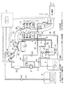
本実施形態は、図1に示すように、エンジンから排出された排出ガスを排気する排気管を担体として構成された触媒11と、該触媒にデカリンを供給するデカリンインジェクタ(燃料供給装置)12とを備え、供給されたデカリンを排気ガスの熱(排気熱)で加熱された触媒上で脱水素反応させる脱水素反応器(反応手段)1と、デカリンの脱水素反応によって生じた混合気体から水素ガスを分離する分離タンク(分離手段)2とを備えている。
In the present embodiment, as shown in FIG. 1, a
脱水素反応器1を構成する触媒11は、排気管13の管外壁(外側表面)の周囲を覆うように触媒金属微粒子を担持して構成されており、脱水素反応器1は、この触媒11を反応器外壁30で覆うように取り囲んで中空を有して構成されている。
The
脱水素反応器1には、6基のデカリンインジェクタ12が触媒11に対向させて配置されており、各デカリンインジェクタ12は、デカリンを貯留するデカリンタンク3と連通するポンプP5を備えた供給配管16の複数に分岐された各々の一端で接続されている。この供給配管16によって、脱水素反応器1はデカリンタンク3と連通され、デカリンインジェクタ12から触媒11上に均一にデカリンを供給できるようになっている。
In the
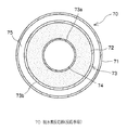
脱水素反応器1について、さらに図2〜3を参照して説明する。図2は、脱水素反応器の側部断面を拡大して示す概略図であり、図3は図2のA−A'線断面図である。
The
排気管13は、一端でエンジンのシリンダ5と排気バルブ27を介して接続され、他端から浄化触媒を介して排出ガスを排気するようになっており(図1参照)、シリンダ5との接続部下流であって浄化触媒の上流に管断面が拡がった太管部が設けられている。なお、排気管13中を挿通する排出ガスの排気方向が下流である。
The
この太管部の排出ガスが挿通する側とは逆側の管外壁には触媒金属微粒子が担持され触媒11が設けられている。更に、この太管部の周囲を覆うようにして反応器外壁30が設けられており、太管部と反応器外壁30との間には中空部が形成されている。
A
デカリンインジェクタ12は、図2および図3に示すように、触媒11上にデカリンを広角に噴霧等して均一にデカリンの液膜状態を形成できるように設けられている。デカリンが触媒上で液膜状態となるように供給されると、反応転化率が高められ、水素ガスを効率良く生成することができる。
As shown in FIGS. 2 and 3, the
触媒が僅かに湿潤した液膜状態では、過熱(デカリンの沸点を越える温度での加熱)・液膜状態での脱水素反応のとき水素ガス生成量は最大になる。これは、デカリンの蒸発速度が、基質液量(デカリンの液量)が少ない程小さくなり、蒸発速度が小さくかつ高温の状態で脱水素反応させることにより転化率が向上するからである。すなわち、蒸発速度は液量・伝熱面積・加熱源と沸点との温度差の各々に比例するので、液体デカリンの量が少なければ蒸発速度が小さくなる。液体デカリンは、加熱触媒上(例えば、200〜350℃)でも液膜状態で存在するので、触媒活性サイトは液相からのデカリンの速やかな吸着により充分に高い被覆度で常時補填される。すなわち、触媒表面上で液膜状態で脱水素反応させることにより、触媒表面上で気体で反応させるよりも優れた反応性が得られる。 In a liquid film state in which the catalyst is slightly wet, the amount of hydrogen gas generated becomes maximum in the case of overheating (heating at a temperature exceeding the boiling point of decalin) and a dehydrogenation reaction in the liquid film state. This is because the evaporation rate of decalin decreases as the amount of the substrate liquid (the amount of decalin) decreases, and the conversion rate is improved by performing the dehydrogenation reaction at a low evaporation rate and at a high temperature. That is, since the evaporation rate is proportional to each of the liquid amount, the heat transfer area, and the temperature difference between the heating source and the boiling point, the evaporation rate decreases as the amount of liquid decalin is small. Since liquid decalin exists in a liquid film state even on a heated catalyst (for example, at 200 to 350 ° C.), the catalytically active sites are constantly filled with sufficiently high coverage by rapid adsorption of decalin from the liquid phase. That is, by performing a dehydrogenation reaction in the form of a liquid film on the catalyst surface, superior reactivity can be obtained as compared with a reaction on the catalyst surface with a gas.
排気管13の前記太管部より上流側の、排気管13と反応器外壁30との接合部には、接合部からの混合気体の漏れを防止するためのシール材31が設けられている。一方、排気管13の太管部より下流側には、排気管13に沿うようにして混合気体が通過するための流路30aが設けられており、発生した混合気体を挿通する場合に、特に混合気体中のナフタレンが冷えて凝縮することなく、気体状態のまま挿通できるようになっている。
A sealing
排気管13の触媒11が設けられた部位(太管部)の内側、すなわち排出ガスが挿通する管内壁側には、該管内壁に沿って管内壁から突出した板状の突起32が複数設けられている。これにより、排出ガスと排気管とがダイレクトに接する接触面積を増すことができるため、排出ガスによる排気熱の熱伝達効率が高められ、触媒11の温度、特にデカリンの脱水素反応時における触媒温度の低下を防止することができる。
A plurality of plate-
また、脱水素反応器1には、図1に示すように、バルブV1とポンプP1と逆止弁とを備えた脱水素反応により発生した混合気体(水素リッチガス)を排出するための排出管14の一端と、バルブV2とポンプP2と逆止弁とを備えた冷却液化したナフタレンおよび未反応デカリンの混合液を排出するための戻し配管15の一端とが接続されており、排出管14によって分離タンク2と、戻し配管15によってデカリンタンク3と各々連通されている。
As shown in FIG. 1, the
分離タンク2は、排出管14の他端と接続されており、排出管14を挿通して脱水素反応器1で発生した混合気体が導入されるようになっている。分離タンク2の上部壁面には、供給配管16から分岐した分岐端で接続された分離用インジェクタ10が設けられており、導入された混合気体に適宜ポンプP7を駆動させデカリン噴霧等して供給できるようになっている。分離タンク2に導入された混合気体中の気相ナフタレンはデカリンに溶解され、水素ガスと分離される。デカリンに溶解されたナフタレンはナフタレン溶液として分離タンク底部に一旦貯留される。
The separation tank 2 is connected to the other end of the
また、分離タンク2の上部には、タンク中の水素圧を検出するための水素圧センサ29が設けられている。分離タンク2内の水素ガスを加圧または高圧状態にしたり、配管17側の圧力を低圧(例えば負圧)にすることで水素排出効率を向上させることができる。
A
分離タンク2の側部には、ポンプP4と逆止弁とを備えた水素ガスを挿通するための配管17の一端が接続されており、底部にはバルブV3を備えた配管18が接続され、配管18を介して戻し配管15と連通されている。分離された水素ガスは、配管17を挿通して分離タンク2から排出され、また分離タンク2に貯留されたナフタレン溶液は、配管18を介して戻し配管15を挿通してデカリンタンク3に導入できるようになっている。
One end of a
デカリンタンク3は、デカリンを貯留し、タンク上部にはデカリンを供給するための供給配管16が設けられている。貯留されたデカリンは、供給配管16によって脱水素反応器1および分離タンク2に供給できるようになっている。タンク底側には、戻し配管15の他端が接続されており、脱水素反応器1から排出され液化したナフタレンと未反応デカリンを含む混合液、および分離タンク2から排出されたナフタレン溶液が導入されるようになっている。
The decalin tank 3 stores decalin, and a
デカリンタンク3には、タンク内に略水平の隔壁を設けることができ、該隔壁によって区画された一方の室を、デカリンを貯留するデカリン貯留部とし、他方の室を、デカリンの脱水素反応により生じかつ水素ガスが除去された後のナフタレンを含む混合液を貯留する混合物貯留部とした二室を有するように構成してもよい。前記隔壁は、該隔壁面の法線方向に移動可能に設けることができ、混合液が少ないときにはデカリン貯留部の容積を大きくして満タンのデカリンを貯留でき、水素の生成量の増大、すなわち混合液の量が増大し、逆にデカリンが減少したときには自動的に隔壁を混合物貯留部の容積が大きくなる方向に移動させることで多量の混合液を貯留できる。 The decalin tank 3 can be provided with a substantially horizontal partition in the tank. One of the chambers defined by the partition is a decalin storage part for storing decalin, and the other chamber is formed by a dehydrogenation reaction of decalin. You may comprise so that it may have two chambers used as the mixture storage part which stores the mixed liquid containing naphthalene after the generated and the hydrogen gas was removed. The partition wall can be provided so as to be movable in the normal direction of the partition wall surface.When the mixed liquid is small, the volume of the decalin storage unit can be increased to store a full tank of decalin, and the amount of generated hydrogen increases, that is, When the amount of the mixture increases and conversely the decalin decreases, a large amount of the mixture can be stored by automatically moving the partition walls in the direction in which the volume of the mixture storage section increases.
エンジンのシリンダ5には、ガソリン(燃料)を空気や水素と共に混合ガスとしてシリンダ内に供給するための吸気管25と、排出ガスを排気するための排気管13とがそれぞれ吸気バルブ26、排気バルブ27を介して接続されている。また、シリンダヘッドには、シリンダ内の混合ガスに点火するための点火プラグ24が設けられている。
In the
吸気管25には、配管17の他端に接続された水素供給用インジェクタ18と、ポンプP6を備えたガソリンを供給するための供給配管23の一端に接続されたガソリン供給用インジェクタ19とが設けられている。水素供給用インジェクタ18は、配管17によって分離タンク2と連通され、吸気管25内に水素を添加できるようになっており、またガソリン供給用インジェクタ19は、供給配管23によってガソリンタンク4と連通され、吸気管25内にガソリンを供給できるようになっている。これにより、水素およびガソリンを含む混合ガスをシリンダ内に供給することができる。
The
配管17には、水素を貯えると共に水素供給用インジェクタ18に水素を供給するバッファタンク20と、水素供給用インジェクタ18への水素供給圧を所望圧に制御するためのレギュレーター21とが設けられており、更に水素供給用インジェクタ18とレギュレーター21との間には水素供給圧が過大とならないようにリリーフ弁(リリーフバルブ)を備えた迂路が設けられている。
The
ガソリンタンク4は、主燃料であるガソリンを貯留し、上部に設けられた供給配管23を通じてガソリン供給用インジェクタ19にガソリンを供給できるようになっている。
The gasoline tank 4 stores gasoline as a main fuel, and can supply gasoline to the
また、排気管13における脱水素反応器1のさらに下流には、排出ガス中の窒素酸化物(NOx)濃度を検出するNOxセンサおよび空燃比計測のためのA/Fセンサ、3元触媒(浄化触媒)の上流側で排出ガス中に水素ガスを添加するための水素添加インジェクタ24、並びにグロープラグが設けられている。
Moreover, the further downstream of the
上記した脱水素反応器1および排気管13は、脱水素反応、排気性能(エンジン性能)等に影響を与えない範囲で任意の形状に構成することができ、例えば図3に示す形状など、偏平な幅広薄型の形状に構成することによって車両の床下やエンジンルーム内などの狭いスペースでも配置することができる。
The above-mentioned
水素添加インジェクタ24は、配管17と連通するバルブV4とポンプP3とを備えた配管22の一端で接続されており、分離タンク2で分離された水素ガスの一部を排気管13に供給できるようになっている。排気管13中の排出ガスに水素ガスを添加すると共にグロープラグで燃焼させることにより、排気される排出ガスを更に浄化することができる。
The
上記のデカリンインジェクタ12、水素供給用インジェクタ18、ガソリン供給用インジェクタ19、分離用インジェクタ10、点火プラグ24、NOxセンサおよびA/Fセンサ、水素添加インジェクタ24並びにグロープラグ等は、各々制御装置(ECU)6と電気的に接続されており、ECU6によって制御されている。
以下、本実施形態の制御装置(ECU)6による制御ルーチンについて説明する。なお、ここでは本発明に関係する水素ガス発生制御ルーチンのみを説明する。図4は、イグニッション(IG)スイッチオンで実行されるメインルーチンを示す。 Hereinafter, a control routine by the control device (ECU) 6 of the present embodiment will be described. Here, only the hydrogen gas generation control routine related to the present invention will be described. FIG. 4 shows a main routine executed when an ignition (IG) switch is turned on.
まず、IGスイッチがオンされると、まずエンジンが始動し、ステップ100において温度センサ28を用いて触媒11の温度Tを取り込み、ステップ102において触媒温度Tが予め定められた所定温度T0以下か否かを判断する。このとき、触媒温度Tが所定温度T0以下の場合にはステップ100に戻って再度触媒温度Tを取り込み、触媒温度Tが所定温度T0を超えている、あるいは温度Tを超えた場合には、ECU6と電気的に繋がる図示しない制御用ドライバにより各々のインジェクタ12から予め定めた所定量(触媒表面上で液膜が得られる直前の量)でデカリンが供給される。
First, when the IG switch is turned on, the engine is first started, and in
上記の所定温度は、200〜500℃、好ましくは200〜350℃の間の温度、更に好ましくは280℃にすることができる。この理由は、所定温度が200℃未満であると目的とする脱水素反応の高い反応速度、換言すれば内燃機関や他の水素使用装置の高性能が得られないことがあり、350℃を越えるとカーボンデポジットが生じる可能性を持ち、500℃を越えると実用的でないからである。 The predetermined temperature can be a temperature between 200 and 500C, preferably between 200 and 350C, more preferably 280C. The reason for this is that if the predetermined temperature is lower than 200 ° C., the desired high reaction rate of the dehydrogenation reaction, in other words, the high performance of the internal combustion engine and other hydrogen-using devices may not be obtained, and the temperature may exceed 350 ° C. This is because there is a possibility that carbon deposits will occur, and if it exceeds 500 ° C., it is not practical.
デカリンの供給に際し、ステップ103では各インジェクタからの供給量を予め定めた所定量から徐々に増加させながらデカリンを供給し、生成した水素リッチガスをバルブV1を開いてポンプP1により分離タンク2に送ると共に、次のステップ104において水素圧センサ29で検出された水素圧の値に基づいて水素圧が増加しているか否か、すなわち水素ガス発生量が増加しているか否かを判断する。水素圧が増加している場合にはステップ103に戻って、デカリン供給量を徐々に増加することを繰り返す。これにより、乾燥した触媒上にデカリンが徐々に供給され、これら表面が徐々に湿潤していき、デカリンが液膜状態で供給されるので、水素発生量が最大値に近づく。
When supplying decalin, in step 103, decalin is supplied while gradually increasing the supply amount from each injector from a predetermined amount, and the generated hydrogen-rich gas is sent to the separation tank 2 by the pump P1 by opening the valve V1 and In the
一方、ステップ104において水素圧が低下していると判断されたときは、デカリン供給量が液膜状態より過剰に供給された場合であるので、ステップ106において、低下の程度に応じて全部あるいは一部の制御用ドライバを制御して個々のインジェクタからのデカリン供給量を徐々に減少させながら供給する。これにより、再び水素発生量が最大値に近づく。ステップ108では、水素圧が低下したか否かを判断し、水素圧が未だ低下しない場合にはステップ106に戻ってデカリン供給量を徐々に減少することを繰り返し、水素圧が低下する場合には、デカリン供給量が液膜状態より少なすぎる状態であるので、ステップ103に戻ってデカリン供給量を徐々に増加して供給することを繰り返す。これにより、デカリンが触媒の表面において常に液膜状態で保持され、水素圧、すなわち水素ガス発生量が最大になるようにデカリンが供給される。
On the other hand, when it is determined in
本実施形態では、IGスイッチがオンされると、ガソリン供給用インジェクタ19から供給されたガソリンに空気と共に水素添加インジェクタ18からバッファタンク20内の水素が添加された混合ガスによってエンジンが始動する。始動後シリンダから排出された排出ガスによって排気管13が加熱され、担持された触媒が所定の温度にまで達すると、ポンプP5を駆動してデカリンタンク3からデカリンが供給配管16を挿通して脱水素反応器1の触媒11上に供給される。脱水素反応して発生した水素リッチガス(蒸発した残存デカリンを含んでもよい。)は生成ナフタレンと共に排出管14を挿通して分離タンク2に送られる。
In the present embodiment, when the IG switch is turned on, the engine is started by the mixed gas in which the gasoline supplied from the
分離タンク2に供給された水素リッチガスは、ポンプP7を駆動して分離用インジェクタ10から噴出されたデカリンと接触し、冷却されると共にガス中のナフタレンおよび残存デカリンは供給されたデカリンに溶解されて水素ガスと分離される。高純度に分離された水素ガスは、配管17を挿通してバッファタンク20に供給、貯蔵されると共に、配管17から分岐する配管22と繋がる水素添加インジェクタ24から排気管13中にも供給される。バッファタンク20に供給、貯蔵された水素ガスは、ガソリンの供給タイミングに合わせて水素供給用インジェクタ18から吸気管25に供給される。以上のように、エンジンの排気熱を利用した車両内での水素生成が可能であり、高純度の水素ガスを継続的にエンジンに供給することで排出ガスの浄化、低燃費化が実現されると共に、同時に排出ガスに水素添加し、燃焼させることで排出ガスを更に浄化することができる。
The hydrogen-rich gas supplied to the separation tank 2 is driven by the pump P7 to come into contact with decalin ejected from the
車両を停止させてイグニッション(IG)スイッチをオフした場合は、エンジンが停止されると共に、図示しない割り込みルーチンが起動され、ポンプP5の駆動を停止しデカリンインジェクタ12からのデカリン供給を停止することにより水素ガスの生成を停止させる。デカリン供給を停止した後も少量の水素ガスが発生するため、バルブV1を開きポンプP1を駆動させて発生した水素ガスを分離タンク2を経由してバッファタンク20に貯蔵する。このとき、ポンプP7が駆動されて分離タンク2にはデカリンが供給される。
When the vehicle is stopped and the ignition (IG) switch is turned off, the engine is stopped, an interrupt routine (not shown) is started, the drive of the pump P5 is stopped, and the supply of decalin from the
エンジン停止後脱水素反応器内が冷却された後、ナフタレンおよび未反応デカリンが液化し器内に残ったこれらの混合液は、バルブV2を開きポンプP2を駆動することによってデカリンタンク3に導入される。このとき、分離タンク2で溶解されたナフタレンは、デカリンと混合したナフタレン溶液としてバルブV3を開いて戻し配管15を介してデカリンタンク3に導入される。導入されたナフタレンは、液中へ導入する等の過程で冷却、凝縮されてタンク底部に沈降、貯留される。貯留されているデカリン中のナフタレン含有率は液面側に近づくほど低下するため、液面に近いデカリンを脱水素用燃料として用いることができる。
After the engine is stopped and the inside of the dehydrogenation reactor is cooled, the naphthalene and unreacted decalin are liquefied and these mixed liquids remaining in the reactor are introduced into the decalin tank 3 by opening the valve V2 and driving the pump P2. You. At this time, the naphthalene dissolved in the separation tank 2 is introduced into the decalin tank 3 via the
また、デカリンとテトラリンとを混合して用いることにより、デカリンの脱水素反応の前にテトラリンが脱水素反応するので、速やかに水素ガスを発生させることができる。ここで、デカリンタンク内あるいはデカリンタンクとは別のタンク内にデカリンと分離してテトラリンを貯留し、このテトラリンを加熱された触媒上でデカリンの脱水素反応前に脱水素反応させることにより、速やかに多量の水素ガスを発生させることができ、より迅速に水素生成を行なうことができる。 In addition, by using a mixture of decalin and tetralin, tetralin undergoes a dehydrogenation reaction before dehydrogenation of decalin, so that hydrogen gas can be generated quickly. Here, the decalin is separated from decalin in a decalin tank or a tank different from the decalin tank, tetralin is stored, and the tetralin is dehydrogenated on the heated catalyst before the dehydrogenation of decalin, whereby the dehydrogenation reaction is quickly performed. A large amount of hydrogen gas can be generated, and hydrogen can be generated more quickly.
(第2実施形態)
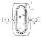
本発明の水素ガス生成装置の第2実施形態を図5を参照して説明する。本実施形態は、第1実施形態の脱水素反応器を分岐された排気管に設けることで複数の脱水素反応器を備えると共に、デカリンタンクおよび分離タンクを単一の貯留分離タンクに代え、単一タンクにデカリンおよび生成ナフタレンを共に貯留するようにし、かつ水素ガスをも分離可能としたものである。なお、燃料は第1実施形態で使用した燃料を用いることができ、第1実施形態と同様の構成要素には同一の参照符号を付してその詳細な説明を省略する。
(2nd Embodiment)
A second embodiment of the hydrogen gas generator according to the present invention will be described with reference to FIG. This embodiment includes a plurality of dehydrogenation reactors by providing the dehydrogenation reactor of the first embodiment in a branched exhaust pipe, and replaces the decalin tank and the separation tank with a single storage / separation tank. In one tank, both decalin and naphthalene formed are stored, and hydrogen gas can be separated. Note that the fuel used in the first embodiment can be used as the fuel, and the same reference numerals are given to the same components as those in the first embodiment, and detailed description thereof will be omitted.
排気管13は、シリンダ5との接合部下流で分岐し、2本の排気管13’が形成されており、この排気管13’の各々において脱水素反応器1が設けられている。脱水素反応器は、上記の第1実施形態と同様に構成することができる。また、排気管13’の管断面が拡がった太管部の下流側には、発生した混合気体(水素リッチガス)が通過するための流路30aが排気管13’に沿って設けられており、二つの脱水素反応器1はいずれも排出管14と戻し排管15とで流路30aを介して貯留分離タンク60と連通されている。
The
本実施形態は、図5に示すように、デカリン64を貯留し、かつ貯留されたデカリンにデカリンの脱水素反応により生成された水素ガスとナフタレンの混合気体(水素リッチガス)が供給されると共に、排出口から水素ガスを排出する貯留分離タンク60を備えている。
In the present embodiment, as shown in FIG. 5, the
貯留分離タンク60は、内部に密閉してデカリン64を貯留可能に構成され、貯留分離タンク60の上部壁面には、デカリン64を供給するためのバルブを備えたデカリン供給管65と、液化したデカリンと未反応デカリンの混合液を回収する戻し配管15とが設けられており、また、バッファタンク20に水素を挿通するためのポンプP4を備えた配管17の一端が接続されて排出口が形成されている。デカリン64は、貯留分離タンク60の上方に空隙を有する範囲でデカリン供給管65から供給できるようになっており、脱水素反応器1で生成された水素ガスはデカリン中を浮上し排出管17を挿通してエンジンに供給できるようになっている(図1参照)。また、貯留分離タンク60の上部壁面には水素圧を検出する水素圧センサ29が取り付けられており、底部には貯留されたナフタレン62を排出するためのバルブを備えた排出管66が設けられている。
The storage / separation tank 60 is configured to be capable of storing the
貯留分離タンク60の底面側の側壁には、脱水素反応器1と連通する排出管14がデカリン64中にその他端が位置するように設けられている。液中となる排出管14の他端からは、脱水素反応器1で生成された水素ガスおよび気相ナフタレンの混合ガス(水素リッチガス;蒸発して残存する残存デカリンを含んでもよい)を液中において供給可能なようになっている。
On the side wall on the bottom side of the storage / separation tank 60, a
貯留分離タンク60の内部には、デカリン64の液面と略水平に分離膜61が備えられ、浮上する水素ガス63を透過し、ナフタレン62のデカリン内での拡散を抑えて分離膜61の下方に貯留することができる。
Inside the storage / separation tank 60, a
分離膜は、ナフタレン(脱水素生成物)がデカリン(脱水素用燃料)中に拡がるのを抑制し、水素生成のために供給されるデカリン中におけるナフタレン含有率を低く抑えることができる。水素生成のために供給されるデカリン等の脱水素用燃料にナフタレン等の脱水素生成物が含まれると、相対的に脱水素反応に寄与し水素を放出する脱水素用燃料含有比が低下して水素生成効率が低下してしまうが、分離膜を設けることによって単一のタンク内で脱水素生成物と分けつつ脱水素用燃料を貯留できるため、区画された一方の側に脱水素生成物を貯留すると同時に他方の側では脱水素生成物含量の少ない脱水素用燃料の供給が可能となる。分離膜は、少なくとも、ナフタレンを高濃度に含む側から他方の側へのナフタレンの濃度分布の拡がりを抑え得る程度に仕切ることができる。このとき、液中の戻し配管15の出口周辺でナフタレン量が不均一になると局部的に粘度上昇等を来すことがあるため、水素ガスの液中での移動速度を損なわないようにすることが望ましい。
The separation membrane can suppress the spread of naphthalene (dehydrogenation product) into decalin (fuel for dehydrogenation), and can reduce the naphthalene content in decalin supplied for hydrogen generation. If a dehydrogenation fuel such as decalin supplied for hydrogen generation contains a dehydrogenation product such as naphthalene, the content ratio of the dehydrogenation fuel that relatively contributes to the dehydrogenation reaction and releases hydrogen decreases. However, by providing a separation membrane, the dehydrogenation fuel can be stored in a single tank while being separated from the dehydrogenation product. And at the same time supply of dehydrogenation fuel with low dehydrogenation product content on the other side. The separation membrane can be partitioned at least to such an extent that the spread of the concentration distribution of naphthalene from the side containing high concentration of naphthalene to the other side can be suppressed. At this time, if the amount of naphthalene becomes non-uniform around the outlet of the
分離膜61は、その膜面の法線方向(図5中の矢印方向A)と略平行に移動可能に構成されている。分離膜の移動は、貯留分離タンク内部の区画された領域の容積を可逆的に変えることができることが望ましく、生成ナフタレン量に合わせて任意に変えることができる。
The
貯留分離タンク60における分離膜61の位置関係としては、生成されたナフタレンの量が少ないときにはナフタレン貯留側の容積を小さくして満タンとなるデカリンを貯留し、水素ガスの生成に伴って徐々にデカリンが減少し、逆にナフタレンの量が増大したときには、その生成量に応じてナフタレンを貯留する側の容積を大きくすることで多量のナフタレンを貯留することができる。すなわち、デカリンが満タンであるときには分離膜61はタンク最下部に位置し、ナフタレン量の増大に応じて分離膜は自動的に上方に移動し、ナフタレン供給側の容積が拡大される。このように、デカリンとナフタレンの物理的な相対量に応じた分離膜の移動により、タンクの有効利用が図れ、狭い設置場所への設置や装置全体の軽量化を達成することができる。
As for the positional relationship of the
分離膜は、水素ガスを透過できると共に、デカリン中でのナフタレンの拡散を抑制し、かつデカリンに対して安定なものであれば、特に制限はなく公知のものの中から適宜選択することができる。例えば、水素透過性でかつ水素ガス以外は物質非透過性(若しくはナフタレン低透過性)のもの、ナフタレンを除いては透過性のものが使用できる。また、分離膜は、変形し難い板状のものでも伸縮可能な軟性、弾性を有するものでもよい。 The separation membrane is not particularly limited and may be appropriately selected from known ones as long as the separation membrane can permeate hydrogen gas, suppress diffusion of naphthalene in decalin, and is stable to decalin. For example, a material that is permeable to hydrogen and non-permeable to substances other than hydrogen gas (or low in naphthalene), and permeable except for naphthalene can be used. Further, the separation membrane may be a plate-like material that is hardly deformed or a material having flexibility and elasticity that can be expanded and contracted.
具体的な例として、メッシュ状のフィルタ膜や、ナフタレンを高濃度に含む側から水素ガスが透過するときに開弁され、かつ逆側から圧がかかった場合に閉弁される多数の逆止弁が格子状またはランダムに配列された逆止弁膜などが挙げられ、材質は樹脂材、金属材、シリコーン材、ゴム材など適宜選択できる。 As a specific example, a large number of non-return valves that are opened when hydrogen gas permeates from a mesh-shaped filter membrane or a side containing a high concentration of naphthalene and closed when pressure is applied from the opposite side. A check valve membrane in which valves are arranged in a lattice or randomly is exemplified, and the material can be appropriately selected from a resin material, a metal material, a silicone material, a rubber material, and the like.
分離膜61の膜面の上方には、ナフタレン含有比の低いデカリン64を、デカリンの脱水素反応を行なう脱水素反応器1に供給するための供給配管16の他端が取り付けられ、脱水素反応器と連通されている。この他端を分離膜61の膜面近傍から上方に配置することにより、ナフタレン含量比の低いデカリンを供給することができ、水素生成効率を高めることができる。
Above the membrane surface of the
上述した実施形態では、水素生成用の燃料としてデカリンを用いた例を中心に説明したが、既述のデカリン以外の脱水素用燃料を用いた場合においても同様である。また、内燃機関として、ガソリンエンジンを例に説明したが、本発明はガソリンエンジン以外のディーゼルエンジンや水素エンジン等の内燃機関に適用することもできる。 In the above-described embodiment, an example in which decalin is used as a fuel for hydrogen generation has been mainly described, but the same applies to a case where a dehydrogenation fuel other than the above-described decalin is used. Further, the gasoline engine has been described as an example of the internal combustion engine, but the present invention can be applied to an internal combustion engine such as a diesel engine or a hydrogen engine other than the gasoline engine.
(第3実施形態)
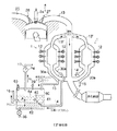
本発明の水素ガス生成装置の第3実施形態を図6および図7を参照して説明する。図6は、本発明の第3実施形態を示す概略構成図である。また、図7は、図6のB−B’断面図である。本実施形態は、第1実施形態の脱水素反応器に転用可能な脱水素反応器である。なお、燃料としては、メチルシクロヘキサンを用い、メチルシクロヘキサンを高温触媒の存在下で反応させた場合にトルエンと水素ガスとが生成するメチルシクロヘキサン/トルエン反応を利用するものである。また、第1実施形態と同様の構成要素には同一の参照符号を付してその詳細な説明を省略する。
(Third embodiment)
A third embodiment of the hydrogen gas generator of the present invention will be described with reference to FIGS. FIG. 6 is a schematic configuration diagram showing a third embodiment of the present invention. FIG. 7 is a sectional view taken along the line BB 'of FIG. This embodiment is a dehydrogenation reactor that can be diverted to the dehydrogenation reactor of the first embodiment. In addition, methylcyclohexane is used as a fuel, and a methylcyclohexane / toluene reaction that generates toluene and hydrogen gas when methylcyclohexane is reacted in the presence of a high-temperature catalyst is used. Further, the same components as those in the first embodiment are denoted by the same reference numerals, and detailed description thereof will be omitted.
本実施形態における脱水素反応器70は、図6に示すように、反応器外壁71内に、触媒72が備えられた反応室73と、排出ガスが流通する排気管74と、触媒72にメチルシクロヘキサンを供給するインジェクタ(燃料供給装置)76とを備えており、更に反応器外壁71と反応室73との間に排出ガスの流通路75が設けられている。
As shown in FIG. 6, a
脱水素反応器70には、図6および図7に示すように、反応室73に設置された触媒72の中心を貫通するように排気管74が設けられている。また、脱水素反応器70に収納された反応室73の周りには、外周壁73bを覆うように流通路75が設けられている。このように、脱水素反応器70の排気管74および流通路75が図1における排気管13の一部を担うように構成されており、エンジンから排出された排出ガスが挿通するようになっている。尚、反応室73の内周壁73aは、排気管74の壁面を兼ねて構成されていてもよい。
As shown in FIGS. 6 and 7, the
反応室73には、上部と底部とに一定領域の空間を残して多孔質構造を有する触媒72が密に設置されており、加熱された触媒72にメチルシクロヘキサンを供給できるように構成されている。加熱された触媒72上に供給されたメチルシクロヘキサンは脱水素反応によりトルエンと水素ガスとを生成する。また、反応室73の底部には排出管14が接続されており、反応室73で生成した水素ガスを図1に示す分離タンク2に供給できるようになっている。尚、反応室73で生成したトルエンおよび未反応のメチルシクロヘキサンは、図1に示す戻し配管15により排出するように構成することができる。
In the
反応室73の上部と底部との空間には、各々2基ずつインジェクタ76が設置されおり、各インジェクタ76は、その噴射口が触媒72に対向するように設置されている。図6においては、反応室73の上部に設置されたインジェクタ76は斜め下方(紙面下方)に、反応室73の底部に設置されたインジェクタ76は斜め上方(紙面上方)に、噴射口を向けて設置されている。
Two
インジェクタ76は、各々図1におけるタンク3と練通するポンプP5を備えた供給配管16の複数に分岐された各々の一端と接続されており、タンク3から触媒72の上方および下方からメチルシクロヘキサンを供給できるようになっている。触媒72に供給されたメチルシクロヘキサンは、毛細管現象により触媒72の内部にまで浸透し、その過程で反応して水素ガスが生成される。
The
触媒72は、活性炭等の多孔質体にPt等の触媒金属が担持されて構成される。前記触媒金属としては、第1実施形態に挙げたもの同様のものを用いることができる。また、触媒72を構成する多孔質体はハニカム構造を有しており、メチルシクロヘキサンおよび発生した水素ガス等が流通しやすいように構成されている。
The
本実施形態においては、図6および図7に示すように反応室73の上方および下方の空間を残して触媒72が反応室73の内周壁73aおよび外周壁73bに接するように設置されている。このように、ある程度の厚みを有する触媒72を用いることで脱水素反応の反応面積を多くとることができる。触媒72の厚さは目的とする水素生成量等を考慮にいれて適宜選定すればよい。
In this embodiment, as shown in FIGS. 6 and 7, the
反応室73の中心を貫通するように設けられた排気管74は、脱水素反応器70における排出ガスのメインラインとなり、エンジンから排出された排気ガスが挿通される。排気管74は、触媒72の中心を貫通して設けられるため、排出ガスの熱によって触媒72をその内側(反応室の内周壁73a側)から加熱することができる。また、図6に示すように排気管74は、脱水素反応器70の排気ガス入り口側と出口側とで流通路75と連通する構成となっている。このため、排気管13を流通してきた排出ガスは、紙面上方から脱水素反応器70に供給されると、排気管74と流通路75との各々に挿通し、各々を経て、脱水素反応器70の排出ガス出口側で再び合流し、その後、図1に示す浄化触媒を経て排気される。
An
反応室73の外周壁73bと反応器外壁71とから形成される流通路75は、脱水素反応器70に排出ガスのサブラインの役割を果たし、反応室73の外側を排出ガスが流通するように構成されている。これにより、触媒72を外側(反応室の外周壁73b側)から加熱することができる。
A
このように、排出ガスの流通経路を触媒の内側と外側とに設けることで、触媒72を内側と外側との両側から加熱することができる。これにより、ある程度の厚みを有する触媒を用いた場合であっても、該触媒を均一に加熱することができる。
By providing the exhaust gas circulation paths inside and outside the catalyst in this way, the
また、流通路75の排出ガス入り口側にはバタフライバルブ77が設置されており、流通路75に供給される排出ガスの量を調整できるようになっている。バタフライバルブ77は、通常若しくは低負荷運転時のときなどは開かれており、サブラインである流通路75に排出ガスが挿通されるようになっている。しかし、高負荷運転時など排気ガスの温度が高くなり、触媒72の外側から熱を供給しなくても触媒72の温度が脱水素反応可能な場合には、バタフライバルブ77を閉じ、メインラインのみに排出ガスが流通するように排気ラインを直列状にして、排気効率を向上させることができる。バタフライバルブ77の開度は、状況に応じて適宜調整することができるが、高負荷運転時等には完全に閉じてメインラインのみに排出ガスが挿通するように構成することが好ましい。
A
バタフライバルブ77の開閉は、図1に示すECU6により制御される。また、バタフライバルブ77はアクチュエータ78と連動しており、アクチュエータ78の駆動により開閉される。アクチュエータ78は、図1に示すECU6と電気的に連結しており、ECU6の指令によりアクチュエータが作動し、バタフライバルブ77が開閉される。
The opening and closing of the
本実施形態においてECU6は触媒72の温度に基づいてバタフライバルブ77の開閉を制御するように構成されており、触媒72の温度は、反応室73の壁面に設けられた温度センサ79によってモニタリングされる。また、温度センサ79は、触媒72の外周壁73b側の紙面上下方向の中心部の温度をモニタリングできるように設置される。本実施形態においては、2基の温度センサにより触媒72の温度をモニタリングできるように構成されている。
In the present embodiment, the ECU 6 is configured to control the opening and closing of the
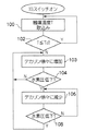
本実施形態の制御装置(ECU)6による制御ルーチンについて説明する。尚、ここでは、本実施形態に関係するバタフライバルブ77の制御ルーチンのみを説明する。図8は、ECUによるバタフライバルブの制御ルーチンを説明するためのフローチャートである。
A control routine by the control device (ECU) 6 of the present embodiment will be described. Here, only the control routine of the
まず、IGスイッチONによりエンジンが始動するとバタフライ制御ルーチンが開始し、ECU6は温度センサ79によって触媒72の外寄りの温度T1を取得する(ステップ200)。次いで、ECU6は、触媒72の温度と予め定められた設定温度Aとを比較する(ステップ201)。この際、温度Aとしては、触媒を外周壁73b側から加熱する必要があるか否かの基準となる温度が設定されている。
First, when the engine is started by turning on the IG switch, the butterfly control routine starts, and the ECU 6 obtains the temperature T 1 outside the
ECU6が、温度T1が設定温度Aよりも低いと判断した場合(ステップ201肯定)、ECU6はアクチュエータ78にバタフライバルブ77を開状態にする駆動信号を発する。ECU6よりバタフライバルブ77を開状態にする駆動信号を受けたアクチュエータは、バタフライバルブ77が開状態のときにはバルブの状態をそのまま維持し、バタフライバルブ77が閉状態のときにはバルブを開き、サブラインである流通路75に排出ガスが挿通できるようにする。(ステップ202)。
When the ECU 6 determines that the temperature T 1 is lower than the set temperature A (Yes at step 201), the ECU 6 issues a drive signal to the
また、ECU6が、温度T1が設定温度A以上であると判断した場合(ステップ201否定)、ECU6はアクチュエータ78にバタフライバルブ77を閉状態にする駆動信号を発する。ECU6よりバタフライバルブ77を閉状態にする駆動信号を受けたアクチュエータは、バタフライバルブ77が閉状態のときにはバルブの状態をそのまま維持し、バタフライバルブ77が開状態のときにはバルブを閉め、サブラインである流通路75への供給を遮断する(ステップ203)。
When the ECU 6 determines that the temperature T 1 is equal to or higher than the set temperature A (No in step 201), the ECU 6 issues a drive signal to the
以上の処理を繰り返すことにより、ECU6は、バタフライバルブ77の開閉状態を制御して、触媒72の加熱効率および排出ガスの排気効率を調整し、水素生成装置全体の性能向上を図ることができる。
By repeating the above processing, the ECU 6 controls the opening / closing state of the
本実施形態によれば、触媒の内側と外側とに排出ガスの流通経路を設けることで、触媒を内側と外側との両側から加熱することができる。このため、厚みのある多孔質の触媒を用いた場合であっても触媒を均一に十分加熱することができ、水素生成量を向上させることができる。 According to this embodiment, the catalyst can be heated from both the inside and the outside by providing the exhaust gas flow paths inside and outside the catalyst. Therefore, even when a thick porous catalyst is used, the catalyst can be uniformly and sufficiently heated, and the amount of hydrogen generated can be improved.
また、排気ガスの流通経路にバルブを設置したことで、エンジンの負荷状態に応じてその排出ガスの経路を制御することができ、排気効率の向上を図ることができる。尚、本実施形態においては、バルブ開閉を触媒の温度に応じて制御する構成としたが、本発明はこれに限定されるものではなく、排出ガスの排出量や燃料の消費量、並びに、エンジンの駆動状態や排気ガスの温度を直接モニタリングするなどして、バルブ開閉の基準としてもよい。 Further, by providing the valve in the exhaust gas flow path, the exhaust gas path can be controlled according to the load state of the engine, and the exhaust efficiency can be improved. In the present embodiment, the valve opening / closing is controlled in accordance with the temperature of the catalyst. However, the present invention is not limited to this, and the amount of exhaust gas discharged, the amount of fuel consumed, and the engine By directly monitoring the driving state of the device and the temperature of the exhaust gas, the reference value for valve opening and closing may be used.
本発明の水素ガス生成装置により生成された水素は、ガソリンや軽油等の燃料に水素添加して燃焼させる内燃機関(ガソリンエンジン、ディーゼルエンジン等)や水素エンジンの燃料として、あるいは車両に搭載された燃料電池などの水素使用装置供給用として用いることができる。 Hydrogen generated by the hydrogen gas generator of the present invention is added to a fuel such as gasoline or light oil and burned by being added to an internal combustion engine (gasoline engine, diesel engine, etc.) or a hydrogen engine, or mounted on a vehicle. It can be used for supplying a hydrogen-using device such as a fuel cell.
1,70…脱水素反応器(反応手段)
2…分離タンク(分離手段)
11,72…触媒
12…デカリンインジェクタ(燃料供給装置)
13,13’…排気管
18…水素供給用インジェクタ(水素供給手段)
30a…混合気体が通過する流路
32…突起
74…排出管(第1の流路)
75…流通路(第2の流路)
76…インジェクタ(燃料供給装置)
77…バタフライバルブ(調整弁)
1,70 ... Dehydrogenation reactor (reaction means)
2. Separation tank (separation means)
11, 72 ...
13, 13 '...
30a: flow
75 ... flow path (second flow path)
76 ... Injector (fuel supply device)
77… Butterfly valve (adjustment valve)
Claims (7)
前記脱水素用燃料の脱水素反応によって生じた混合気体から水素ガスを分離する分離手段と、
を備えた水素ガス生成装置。 A catalyst provided so as to be able to be heated by the heat of the exhaust gas discharged from the internal combustion engine, and a fuel supply device that supplies a dehydrogenation fuel to the catalyst, wherein the dehydrogenation fuel is supplied on the heated catalyst. Reaction means for performing a dehydrogenation reaction;
Separation means for separating hydrogen gas from the gas mixture produced by the dehydrogenation reaction of the dehydrogenation fuel,
A hydrogen gas generator equipped with:
前記脱水素用燃料の脱水素反応によって生じた混合気体から水素ガスを分離する分離手段と、
を備えた水素ガス生成装置。 A catalyst provided so that a first flow path through which exhaust gas discharged from the internal combustion engine flows passes therethrough, and a fuel supply device that houses the catalyst and supplies dehydrogenation fuel to the catalyst. A reaction vessel forming a second flow path through which the exhaust gas flows between the provided and stored catalyst, and the dehydrogenation fuel on the catalyst heated by the exhaust gas. Reaction means for performing a dehydrogenation reaction;
Separation means for separating hydrogen gas from the gas mixture produced by the dehydrogenation reaction of the dehydrogenation fuel,
A hydrogen gas generator equipped with:
Priority Applications (1)
| Application Number | Priority Date | Filing Date | Title |
|---|---|---|---|
| JP2003290318A JP2004189585A (en) | 2002-11-26 | 2003-08-08 | Gaseous hydrogen producing system |
Applications Claiming Priority (2)
| Application Number | Priority Date | Filing Date | Title |
|---|---|---|---|
| JP2002342469 | 2002-11-26 | ||
| JP2003290318A JP2004189585A (en) | 2002-11-26 | 2003-08-08 | Gaseous hydrogen producing system |
Publications (1)
| Publication Number | Publication Date |
|---|---|
| JP2004189585A true JP2004189585A (en) | 2004-07-08 |
Family
ID=32774783
Family Applications (1)
| Application Number | Title | Priority Date | Filing Date |
|---|---|---|---|
| JP2003290318A Pending JP2004189585A (en) | 2002-11-26 | 2003-08-08 | Gaseous hydrogen producing system |
Country Status (1)
| Country | Link |
|---|---|
| JP (1) | JP2004189585A (en) |
Cited By (11)
| Publication number | Priority date | Publication date | Assignee | Title |
|---|---|---|---|---|
| JP2006104000A (en) * | 2004-10-01 | 2006-04-20 | Tokyo Univ Of Science | Hydrogen gas generation equipment |
| JP2006226167A (en) * | 2005-02-16 | 2006-08-31 | Toyota Motor Corp | Internal combustion engine utilizing hydrogen |
| KR100664970B1 (en) | 2004-12-31 | 2007-01-04 | 전상문 | Hybrid internal combustion engine using thermochemical reaction |
| JP2008088922A (en) * | 2006-10-04 | 2008-04-17 | Hitachi Ltd | Hydrogen fueled engine system |
| JP2008130492A (en) * | 2006-11-24 | 2008-06-05 | Toyota Motor Corp | Fuel cell system and fuel cell vehicle |
| JP2010163358A (en) * | 2010-02-15 | 2010-07-29 | Hitachi Ltd | Hydrogen supply apparatus and method for supplying hydrogen |
| JP2010184842A (en) * | 2009-02-13 | 2010-08-26 | Nissan Motor Co Ltd | Fuel reforming apparatus |
| JP2011247235A (en) * | 2010-05-31 | 2011-12-08 | Hitachi Ltd | Energy generation system |
| WO2013103060A1 (en) * | 2012-01-06 | 2013-07-11 | 株式会社 日立製作所 | Power conversion system |
| EP2759691A4 (en) * | 2011-09-22 | 2015-05-27 | Hitachi Ltd | Power conversion system |
| WO2023241421A1 (en) * | 2022-06-14 | 2023-12-21 | 中南大学 | Alcohol fuel cracking hydrogen production apparatus and system |
-
2003
- 2003-08-08 JP JP2003290318A patent/JP2004189585A/en active Pending
Cited By (16)
| Publication number | Priority date | Publication date | Assignee | Title |
|---|---|---|---|---|
| JP4662534B2 (en) * | 2004-10-01 | 2011-03-30 | 株式会社新エネルギー研究所 | Hydrogen gas generator |
| JP2006104000A (en) * | 2004-10-01 | 2006-04-20 | Tokyo Univ Of Science | Hydrogen gas generation equipment |
| KR100664970B1 (en) | 2004-12-31 | 2007-01-04 | 전상문 | Hybrid internal combustion engine using thermochemical reaction |
| JP2006226167A (en) * | 2005-02-16 | 2006-08-31 | Toyota Motor Corp | Internal combustion engine utilizing hydrogen |
| JP2008088922A (en) * | 2006-10-04 | 2008-04-17 | Hitachi Ltd | Hydrogen fueled engine system |
| US8741497B2 (en) | 2006-11-24 | 2014-06-03 | Toyota Jidosha Kabushiki Kaisha | Fuel cell system and fuel cell hybrid vehicle |
| JP2008130492A (en) * | 2006-11-24 | 2008-06-05 | Toyota Motor Corp | Fuel cell system and fuel cell vehicle |
| JP2010184842A (en) * | 2009-02-13 | 2010-08-26 | Nissan Motor Co Ltd | Fuel reforming apparatus |
| JP2010163358A (en) * | 2010-02-15 | 2010-07-29 | Hitachi Ltd | Hydrogen supply apparatus and method for supplying hydrogen |
| JP2011247235A (en) * | 2010-05-31 | 2011-12-08 | Hitachi Ltd | Energy generation system |
| WO2011152366A1 (en) * | 2010-05-31 | 2011-12-08 | 株式会社日立製作所 | Energy-generating system |
| EP2759691A4 (en) * | 2011-09-22 | 2015-05-27 | Hitachi Ltd | Power conversion system |
| WO2013103060A1 (en) * | 2012-01-06 | 2013-07-11 | 株式会社 日立製作所 | Power conversion system |
| JP2013143179A (en) * | 2012-01-06 | 2013-07-22 | Hitachi Ltd | Power conversion system |
| US9660284B2 (en) | 2012-01-06 | 2017-05-23 | Hitachi, Ltd. | Power conversion system |
| WO2023241421A1 (en) * | 2022-06-14 | 2023-12-21 | 中南大学 | Alcohol fuel cracking hydrogen production apparatus and system |
Similar Documents
| Publication | Publication Date | Title |
|---|---|---|
| JP4039383B2 (en) | Internal combustion engine using hydrogen | |
| RU2265920C2 (en) | Hydrogen supply method and mobile system for hydrogen production | |
| US5813222A (en) | Method and apparatus for heating a catalytic converter to reduce emissions | |
| US8061120B2 (en) | Catalytic EGR oxidizer for IC engines and gas turbines | |
| CN102007286B (en) | Hydrogen supply unit for internal combustion engine and method of operating internal combustion engine | |
| US7101411B2 (en) | Apparatus for generating hydrogen gas | |
| JP2004189585A (en) | Gaseous hydrogen producing system | |
| JP2005239479A (en) | Hydrogen gas separating equipment and hydrogen gas generation equipment | |
| CN101457715A (en) | Mobile hydrogen making engine fuel system and device thereof | |
| JP5297251B2 (en) | Hydrogen supply method and hydrogen supply apparatus | |
| FR2860455A1 (en) | System for the production and utilization of hydrogen on board a motor vehicle by the dehydrogenation of organic compounds | |
| JP2005306687A (en) | Hydrogen gas separation apparatus, hydrogen gas production apparatus, and fuel cell system | |
| JP2004251196A (en) | Apparatus for producing reformed gas, method for producing reformed gas employing this apparatus and exhaust emission control system | |
| JP2003343360A (en) | Hydrogen engine system | |
| JP2004231468A (en) | Hydrogen gas generation apparatus | |
| JP2008261331A (en) | Fuel reformer of power source and power source with fuel reformer | |
| GB2388465A (en) | A fuel cell plant | |
| Marsh et al. | SULEV emission technologies for a five cylinder N/A engine | |
| JP2003022835A (en) | Reformer for fuel cell | |
| JP2004359494A (en) | Hydrogen gas generating apparatus | |
| JP2004168631A (en) | Hydrogen gas production system | |
| JP2004107138A (en) | Hydrogen gas generating apparatus | |
| TW201816261A (en) | Waste heat reforming device for generating hydrogen suitable for installation in a waste gas exhausting port of a vehicle and waste heat generated by an engine is utilized as a heat source for reforming action to generate hydrogen | |
| JP2005152854A (en) | Dehydrogenation/hydrogenation apparatus of organic hydride, and carrier used for it | |
| JP2004315305A (en) | Hydrogen gas generation equipment |