【0001】
【発明の属する技術分野】
本発明は、被記録媒体に画像形成した印画物の画像面を転写膜層で覆う(ラミネートする)ためのラミネートフィルム、またこれを用いた印画物のラミネート処理方法及びラミネート加工が施された画像面を有する印画物に関する。
【0002】
【従来の技術】
インクジェット法による記録装置の適用範囲の拡大や高性能化とともに、画像形成に用いる被記録媒体としてはこれまで種々の構成のものが考案されている。例えば、基材上にシリカやアルミナ等の無機多孔質粒子と水溶性樹脂等のバインダを主体としたインク受容層を設けた構成の被記録媒体を用いてインクジェット記録法によりインク受容層へ画像を形成する方法が知られている。かかる構成とすることでインク吸収性やインクの色材への定着を高めることができ高画質の画像を得ることができる。
【0003】
一方、インクジェット記録法を適用して銀塩によるカラー写真や各種印刷法における多色印刷に匹敵する画質及び耐候性を有する画像を形成できれば、画像形成単価を大幅に低減できる可能性がある。
【0004】
銀塩写真や多色印刷に匹敵する多色画像をインクジェット法で形成することを目的とする技術としては、基材上にシリカ等の白色の多孔質微粒子を含むインク受容層を設けた構成を有する被記録媒体を用い、インクジェット記録による画像形成後にインク受容層表面に透明フィルム層をラミネートし、画像濃度の向上や画像表面を平滑化し光沢度を上げることで画像品位を高める方法が知られている。
【0005】
画像面へのラミネートに用いる装置としては、特開平6−91767号公報の提案がある。この公報には、画像が形成された枚葉シートを装置内に送り、連続状の転写膜層付ラミネートフィルムにより枚葉シートをラミネートし、その後ラミネートフィルム基材を剥離することで枚葉シート上にのみラミネート加工を施すことができる。枚葉シートからの剥離は、ラミネートフィルムより枚葉シートのほうが強い「こし」を有していることが利用されており、ラミネート後の枚葉シートの搬送方向に対してラミネートフィルムの搬送方向を鋭角に変化されることで、枚葉シートがラミネートフィルムに追随することができずに先端部分から剥離し、さらに搬送が進むことで枚葉シートが支持体から完全に剥離する構成になっている。このラミネート装置では、枚葉シートを分離する際に切断工程が無く装置の簡略化が可能なことや、切断による不要な切断片などの廃棄物が無いこと、さらに枚葉シートを連続してラミネート加工することができるのためラミネートフィルムの利用効率が高いなどの利点がある。
【0006】
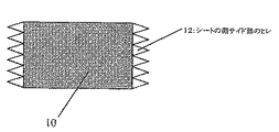
しかし、ラミネートフィルムの転写膜層とフィルム基材との密着性や、転写膜層の膜強度の関係から剥離は良好に行われず、枚葉シートの周辺部分のラミネート加工に不具合が残ってしまう場合が多い。すなわち、枚葉シートの先端部分や後端部分のラミネート未加工部が発生する問題(図2)や、枚葉シートの淵に沿って「ひれ」状に転写膜層が残ってしまう問題(図3)があった。
【0007】
上記の不具合を改善する装置構成として特開平2001−121609号公報の提案がある。この公報では、特に枚葉シートの後端部分の「ひれ」発生を改善するために後端カーター機構を設けた構成になっている。枚葉シートの後端部分が通過する際に位置可変ローラがラミネートフィルム基材側から押し込まれ、この際、枚葉シートの「こし」があるためにラミネートフィルム基材の湾曲に追随することができず後端部分が剥離するという機構が設けられている。この構成により特に後端部分の不具合は改善されるが、ここでも枚葉シートの「こし」を利用した剥離システムになっているため、前記したラミネート未加工部の発生や、「ひれ」の発生があった。
【0008】
上記のラミネート未加工部の発生や、「ひれ」の発生はラミネート加工印画物の外観を悪くし商品価値を低下させてしまう。これらの不具合を解消し、淵部の状態が揃ったラミネート加工印画物を安定して作製するためには、さらに後工程として印画物の周辺を切断する追加工程が必要であった。
【0009】
【発明が解決しようとする課題】
本発明では、前記の枚葉シートの「こし」を利用した剥離機構による簡略で、且つラミネートフィルムの利用効率の高いラミネート装置を用いた場合においても、後工程による切断機構を必要としない安定した剥離性を有する転写膜層付ラミネートフィルムを供給することである。
【0010】
また、本発明による転写膜層付ラミネートフィルムを用いてラミネート加工した印画物の画像品位は未加工時と比較して、画像濃度、画像光沢度の面で大きく向上し、耐光性、耐水性、耐摩擦性など画像堅牢性においても大きな改善がなされるものである。
【0011】
さらに、高温あるいは低温、高湿度などの過酷な保存状態においても印画物の表面にラミネートした表面保護層に「ひび割れ」や「クラック」、「白化」などの不具合がないラミネート加工印画物を得ることである。
【0012】
【課題を解決するための手段】
本発明にかかるラミネート用フィルムは、耐熱性基材と、該耐熱性基材上に剥離可能な転写膜層が設けられ、印画物の画像面上に加熱圧着によって転写膜層を転写するラミネートフィルムにおいて、前記転写膜層が、前記画像面の表面保護層となる第1層と、該第1層上に設けられ前記画像面への接着層となる第2層とを有し且つ、第1層が10ミクロン以下の微粒子を含有する樹脂層からなることを特徴とするラミネートフィルムである。
【0013】
また、本発明にかかるラミネート処理された印画物は、画像面に前記転写膜層がラミネートされており、画像面上に接着した該第2層である接着層の上に該第1層である表面保護層が積層された構成において、該表面保護層に10ミクロン以下の微粒子を含有する樹脂層からなるものである。
【0014】
本発明にかかるラミネートフィルムにおける第1層としては、10ミクロン以下の微粒子の含有量が重量換算で3重量部以上、40重量部以下の範囲であることがこのましい。
【0015】
前記の本発明における微粒子としては、無機酸化物微粒子、有機系の合成ポリマー微粒子が挙げられる。無機酸化物微粒子としてはシリカ、アルミナ、また有機系の合成ポリマー微粒子としてはアクリル系微粒子、シリコーン系微粒子が本発明の好ましい形態として挙げられる。
【0016】
また第1層を構成する樹脂成分の内、分子量5万以上且つガラス転移温度70℃以上のポリマー成分が、微粒子を除いた全重量固形分に対して80重量部以上からなるものである。
【0017】
さらに、前記第1層或いは第2層を構成する樹脂に紫外線吸収性化合物を成分とする高分子材料が含有されていることを好ましい形態とするのものである。
本発明にかかるラミネートフィルムは、インクジェット画像記録方式によって画像形成された被記録媒体に対してラミネート加工を施すことに好適である。
【0018】
また、多孔質無機粒子を含有する部分に画像形成されている被記録媒体において、ラミネート加工を施すと特に好適である。
【0019】
さらに、前記の多孔質無機粒子が非晶質シリカである被記録媒体において、ラミネート加工を施すと特に好適である。
【0020】
【発明の実施の形態】
本発明にかかるラミネートフィルムの一例の構成を図4に示す。耐熱性基材上に、該耐熱性基材側から順に少なくとも表面保護層と接着層とを設けた構成を有するラミネートフィルムである。
【0021】
耐熱性基材は、ラミネート加工の際に転写膜層となる表面保護層と接着層がその形状を保持するのに必要な機械的強度と、画像面への良好な転写および剥離操作が可能である材料を用いる好ましい。このような材料としては、例えばポリエチレンテレフタレート(PET)フィルム、ポリエチレンナフタレート(PEN)フィルム、ポリフェニレンサルファイド(PPS)フィルム、ポリエーテルスルフォン(PES)フィルムなどを挙げることができる。耐熱性基材の厚さは上記の機能が得られるように設定されれば良いため特に限定されるものではないが、5〜50ミクロンの範囲から適宜選択することができる。また、耐熱性基材の転写膜層が積層される面は、積層性や剥離、転写性などを改善する上で各種の処理が施されてもよい。さらに、耐熱性基材の転写膜層が形成される反対面もラミネートフィルムに埃や塵などが付着しずらくするために帯電防止処理、またはブロッキングを防止するために離型処理等が施されても良い。
【0022】
表面保護層としては、印画面の表面平滑性を向上させ高光沢度が得られること、さらに過酷な保存環境下においても光沢度の低下や、白化などの膜の変質、さらにクラックの発生などが少ない点から、分子量およびガラス点移転の高い樹脂を主成分として用いることが良い。分子量としては、重量平均分子量で5万以上、ガラス転移点としては70℃以上であることが好ましい。また、高湿度の環境下に置かれた際に樹脂が水分を吸収し膨潤することによる画質の劣化の点から、非水系の樹脂を用いることが特に好ましい形態である。したがって、表面保護層水溶性の樹脂やエマルジョン樹脂を用いることは望ましくない。上記の特性を踏まえた表面保護層用樹脂の主成分としては、アクリル樹脂、ポリエステル樹脂、メラミン樹脂、ポリアミド樹脂、ポリアリレート樹脂、シリコーン樹脂などのガラス転移点の高い樹脂を用いることができる。また、耐水性、耐溶剤性、耐磨耗性などを特に高めるために熱硬化性、あるいは紫外線硬化性、電子線硬化性の樹脂を用いても良い。また、インクジェット画像記録法による画像形成では染料を用いている場合が多く耐紫外線劣化性が十分でない。このような場合は、紫外線吸収性を有する化合物を上記の樹脂中に含有させることで耐紫外線劣化耐を向上させることができる。紫外線吸収性の化合物を樹脂中に含有させる方法としては、ベンゾトリアゾールなどの紫外線吸収化合物を用いるとよい。これら紫外線吸収性化合物を上記の樹脂に添加して用いる方法や、上記の樹脂成分と共重合させて用いる方法などがある。また上記の樹脂に添加して用いる場合は、高分子量タイプの紫外線吸収化合物を用いることが持続性の面から好ましい。
【0023】
上記のように表面保護層としては、耐候性、耐磨耗性などの点から分子量およびガラス転移点の高い先に挙げた種類の樹脂を用いることが不可欠であるが、一方これらの樹脂は膜強度が高くラミネート加工時の剥離性が良好でない。樹脂の分子量を下げることで膜強度を弱め剥離性を上げることは可能であるが、クラックの発生や耐磨耗性の低下などの点で問題である。
【0024】
すなわち前記に挙げた表面保護膜としての特性を落とさずに、ラミネート時の剥離性を向上させることが重要である。本発明においては、ラミネート加工による剥離を良好に行うために、表面保護層を構成する樹脂中に微粒子を含有させることで、表面保護層としての特性を下げることなくラミネート加工時の剥離が良好に行われるラミネートフィルムを得ることが可能となる。ラミネート後の枚葉シートとラミネートフィルムの搬送方向を鋭角に変化させ、枚葉シートの「こし」を利用し転写膜層をラミネートフィルム基材から引きちぎる剥離方法において、表面保護層を構成する樹脂に含有された微粒子はラミネートフィルムの搬送方向を鋭角に変化させた際の表面保護層への亀裂のきっかけを作り剥離が良好に行われるものである。また、分子量が大きく膜強度が強い表面保護層を構成する樹脂に対しても微粒子の含有は剥離に対して非常に有効に働くため、分子量が小さく膜強度が低い表面保護層を構成する樹脂を用いた場合に発生する前記の耐候性の低下、耐磨耗性の低下などの無いラミネート加工印画物を得ることができる。
【0025】
本発明において表面保護層に含有されうる微粒子としては、無機系微粒子、有機系の合成ポリマー微粒子などが挙げられる。無機系微粒子には、例えばシリカ微粒子、アルミナ微粒子、あるいはその他の無機系顔料微粒子等がある。有機系の合成ポリマー微粒子としては、アクリレート系微粒子、メタクリレート系微粒子、スチレン系微粒子、メラミン系微粒子、ベンゾグアネミン系微粒子、シリコーン系微粒子、フッ素系微粒子等を用いることが可能である。また、有機系の合成ポリマー微粒子を用いる場合は、耐有機溶剤性の高い微粒子を用いることが好ましい。これは、表面保護層を形成する樹脂としては、前記のように非水系の樹脂を用いる方が耐水性などの点で望ましく、その際にトルエンなどの有機溶剤に溶解させた形態で用いられる場合が多く、微粒子の耐有機溶剤性が悪い場合、有機溶剤に溶解または膨潤してしまい微粒子としての効果がなくなってしまうためである。
【0026】
これら無機系微粒子および有機系微粒子の平均粒径としては、10ミクロン以下あることが好ましい。これは、微粒子の粒径がこれより大きくなると、樹脂中に均一に分散させることが困難となり剥離性に対してばらつきが生じる点や、ラミネート加工後の印画物の表面に微粒子が目視により確認され外観を損ねる点などの不具合が生じるためである。以上の点から、粒度分布の広がりが小さい5ミクロン以下の微粒子を用いることがさらに好ましい。また、含有重量としては、表面保護層を構成するすべての材料成分に対して3重量部以上、40重量部以下であることである。3重量部以下の含有量ではラミネート加工時の剥離性の向上に対して効果は少なく、40重量部以上の含有では表面保護層の膜強度が低下し耐磨耗性が低くなることや、透過率が大きく低下しラミネート加工印画物の画像外観を損ねるなどの不具合が生じるため好ましくない。以上の点からさらに好ましい形態としては10重両部以上30重両部以下の範囲である。
【0027】
また、表面保護層の膜厚は、例えば0.5〜15ミクロンとすることができる。
【0028】
上記のように、表面保護層の形成は、例えばアクリル系ポリマーと有機系微粒子を適当な溶剤により攪拌、混合して微粒子が分散した塗工液を調整し、この塗工液を耐熱性基材上に所定の膜厚が得られるように塗工および乾燥することで行うことができる。塗工方法としては、例えばロールコーティング法、グラビアコーティング法、ロードバーコーティング法、スロットダイコーティング法などの種々の塗工方法により行うことができる。尚、塗工に際して、塗工液には必要に応じて分散剤、表面張力調整剤、消泡剤等を添加しても良い。
【0029】
表面保護層上に設けられる接着層は、熱可塑性樹脂を主成分として構成することができ、画像面に加圧圧着されることで溶融し、表面保護層を画像面上に密着性よく形成できる材料が用いられる。このような熱可塑性樹脂のガラス点移転は、0℃以上、80℃以下であることが好ましい。80℃以上のガラス転移点を有する熱可塑性樹脂を主成分として用いた場合、加圧圧着時の溶融が十分でなく表面保護層を密着性良く画像面上に形成することが難しい。また、0℃以下の場合は画像面上への接着は良好に行われるが、ラミネートフィルム保存時にラミネートフィルム耐熱性基材反対面との融着、すなわちブロッキングが発生しやすくなるため好ましくない。上記に示した熱可塑性樹脂としては、塩化ビニル樹脂系、酢酸ビニル樹脂系、塩化ビニル−酢酸ビニル共重合樹脂系、エチレン−酢酸ビニル共重合樹脂系、アクリル樹脂系、ウレタン樹脂系、ポリエステル樹脂系、ポリエチレン樹脂系、ポリプロピレン樹脂系などが挙げられる。また、表面保護層の場合と同様に、印画物の耐紫外線劣化性を向上する目的で、紫外線吸収性の化合物を樹脂中に含有させても良い。前記と同様に紫外線吸収性の化合物を添加して用いる方法や共重合して用いる方法などが適宜用いられる。なお、接着層の膜厚は、画像面の凹凸の程度によって異なるが2〜30ミクロンに適宜設定することができる。
【0030】
これら接着層の形成においても、表面保護層形成と同様に例えばロールコーティング法、グラビアコーティング法、ロードバーコーティング法、スロットダイコーティング法などの種々の塗工方法により行うことができる。また、塗工に際して、塗工液には必要に応じて分散剤、表面張力調整剤、消泡剤、耐ブロッキング防止剤等を添加しても良い。
【0031】
本発明のラミネートフィルムにおける転写膜層の層構成は、少なくとも前記の表面保護層と接着層を耐熱性基材上に積層して構成されるものであるが、必要に応じて上記の2層の密着性向上等を目的として中間層を設けても良い。
【0032】
以上説明した構成のラミネートフィルムを用いて、画像面へラミネート加工を施し転写膜層を形成することができる。ここで画像形成には種々の被記録媒体および種々の記録方法を用いることができるが、本発明において被記録媒体および記録方法としては、基材上にインク受容層、特に多孔質無機粒子を主成分としたインク受容層付き被記録媒体に対してインクジェット記録法を用いて画像を形成された場合が好ましい形態である。このような被記録媒体のインク受容層の形成に用い得る多孔質無機粒子としては、シリカ、アルミナ、炭酸マグネシウム、シリカアルミナ混晶、シリカマグネシウム混晶等を用いることができる。また、インク受容層を形成する際には、必要に応じて結着材を用いることができ、例えば、ポリビニルアルコール、酢酸ビニル、アクリル等の水溶性高分子またはエマルジョンなどが利用できる。多孔質無機粒子と結着材との配合比は、例えば多孔質無機粒子100重量部に対して結着材を10 〜200 重量部、好ましくは25〜100重量部の範囲から選択することができる。更に、インク受容層には、分散剤、蛍光染料、pH調製剤、潤滑剤、界面活性剤等の各種添加剤を必要に応じて添加することができる。インク受容層の層厚は例えば30〜60μmの範囲から選択するのが好適である。
【0033】
一方、インクジェット記録における記録方式は、静電吸引方式、圧電素子を用いる方式、発熱素子を用いる方式等その記録方式は特に限定されない。インクジェット記録に用いるインクとしては、水性媒体に、染料や顔料等の色材を含有させたものなど、インクジェット記録方式に適用できるものであればよい。カラー記録を行う場合は、常法に従って、シアン、マゼンタ、及びイエロー、更には必要に応じてブラックを用いた減色混合によりフルカラー画像を形成することができる。
【0034】
本発明のラミネートフィルムを用いた画像形成後のインク受容層上への転写膜の形成は例えば次のようにして行うことができる。まず、被記録媒体のインク受容層に画像情報に応じてインクジェット記録法により画像を形成したところで、画像面の上方からラミネートフィルムを重ね合わせ、この重ね合わせた部分を一対の対向するローラ間に通す等の方法によって加熱下に加圧することで、ラミネートフィルムの転写膜層をインク受容層に圧着する。更に、ラミネートフィルムの一部を構成している耐熱性基材を剥離して、ラミネート加工が施された印画物(プリント)を得ることができる。
【0035】
このような保護層の形成工程を行う装置の一例を図1に示す。図1の装置は、ロールに巻取られた状態である被記録媒体のインク受容層側の面に対してインクジェット記録を行うインクジェット記録部と、インクジェット記録された画像面に対してラミネート加工を施すラミネート処理部とを有する。
【0036】
インクジェット記録部はインクジェット記録ヘッドを有し、被記録媒体のインク受容層に対して画像情報に応じてインクを付与し、画像を形成する。画像形成後、カッターにより画像は適当な大きさの枚葉シートに裁断される。次に、枚葉シートのインク受容層側に対してラミネートフィルムの転写膜層側から張り合わされ、一対のローラ間を通り、必要に応じた加熱下で加圧される。この処理によってラミネートフィルムの接着層が、インク受容層に圧融着される。ローラ対通過後に枚葉シートに張り合わされたラミネートフィルムは、剥離部9で鋭角に進行方向を変化され枚葉シートは「こし」があるために追随できず、先端から剥離してインク受容層上に転写膜層を有する印画物(プリント)が得られる。ローラ対における加圧力や加熱温度は用いるラミネートフィルムの種類に応じて設定することができる。
【0037】
【発明の実施の形態】
以下実施例等により本発明を更に詳細に説明する。
【0038】
(被記録媒体の作製)
シリカ(水澤化学工業株式会社;商品名:ミズカシルP−50)1重量部に対してバインダ樹脂エマルジョン高松油脂株式会社;商品名;NS120−XK)0.7重量部を合せて固形分含量20 重量%となるように添加、分散させて塗工液を調製した。この塗工液を基材としての坪量186g/m2の上質紙に、乾燥後の膜厚が30μmになるようにスロットダイコーターで塗工し、乾燥させて被記録媒体を得た。
【0039】
(実施例1)
透明ポリエチレンテレフタレートフィルム(、厚さ38ミクロン)を耐熱性シート状基材として、この基材上に下記の組成の塗工液を用いて乾燥後の塗布膜厚5ミクロンとなるようにグラビアコート法によってコーティングして表面保護層を形成した。
組成
アクリルポリマー : 9重量部
(三菱レイヨン(株)製 商品名:ダイヤナールBR−82
分子量15万、ガラス転移温度95℃)
紫外線吸収性ポリマー : 3重量部
(大塚化学(株)製 商品名:PUVA−30M、分子量5万)
シリコーン微粒子 : 3重量部
(GE東芝シリコーン(株) 商品名:トスパール120、平均粒子径2ミクロン)
トルエン :45重量部
メチルエチルケトン :40重量部
次に、表面保護層の上にアクリル系エマルジョン溶液(日信化学工業株式会社:ビニブラン2706、ガラス転移点温度:21℃)を乾燥膜厚15μmとなるようにグラビアコート法により接着層を積層塗工しラミネートフィルムを得た。
【0040】
次に、前記による被記録媒体のインク受容層に対して、インクジェットプリンター(キヤノン株式会社製:BJF8500)を用いて、1インチ四方内にインク液滴体積8.5plのインク滴を720000発打ち込むインク量を100%として、ブラック100%、シアン、マゼンタ、イエローをそれぞれ50%ずつ打ち込んで黒色を形成した。
【0041】
インク打ち込み後、ラミネートフィルムと被記録媒体におけるインク受容層側が接するようにこれらを重ね合せて、回転する一対のローラ間(ロール直径63mm、線圧7N/cm、温度150℃)に通し、加熱加圧処理を行いインク受容層上に、転写膜層を形成するとともに、ラミネートフィルム耐熱性基材を剥離して、ラミネート加工が施された印画物を得た。
【0042】
(実施例2)
下記の組成の塗工液を用いて表面保護層を形成した以外は(実施例1)と同様にしてラミネートフィルムを作製し、前記の被記録媒体に対して(実施例1)と同様にして画像形成およびラミネート加工を施した。ここで微粒子としては、無機系微粒子であるコロイダルシリカ(日産化学工業(株) 商品名:MEK−ST、平均粒子径0.01〜0.02ミクロン)を用いた。
組成
アクリルポリマー : 9重量部
(三菱レイヨン(株)製 商品名:ダイヤナールBR−82
分子量15万、ガラス転移温度95℃ )
紫外線吸収性ポリマー : 3重量部
(大塚化学(株)製 商品名:PUVA−30M、分子量5万)
コロイダルシリカ : 10重量部
(日産化学工業(株) 商品名:MEK−ST
平均粒子径0.01〜0.02ミクロン)
トルエン :45重量部
メチルエチルケトン :33重量部
(実施例3)
微粒子として、有機系の合成ポリマー微粒子であるアクリル微粒子(総研化学(株) 商品名:MX−150、平均粒子径1.5ミクロン)を用いた以外は実施例1と全く同様にして表面保護層を形成し、さらに実施例1と同様にして接着層を形成しラミネートフィルムを作製した。前記の被記録媒体に対して(実施例1)と同様にして画像形成およびラミネート加工を施した。
【0043】
(比較例1)
シリコーン微粒子として、平均粒子径12ミクロン(GE東芝シリコーン(株) 商品名:トスパール3120)のものを用いた以外は実施例1と全く同様にして表面保護層を形成し、さらに実施例1と同様にして接着層を形成しラミネートフィルムを作製した。前記の被記録媒体に対して(実施例1)と同様にして画像形成およびラミネート加工を施した。
【0044】
(比較例2)
下記の組成の塗工液を用いて表面保護層を形成した以外は(実施例1)と同様にしてラミネートフィルムを作製し、前記の被記録媒体に対して(実施例1)と同様にして画像形成およびラミネート加工を施した。
組成
アクリルポリマー :11.85重量部
( 三菱レイヨン(株)製 商品名:ダイヤナールBR−85
分子量28万、ガラス転移温度105℃)
紫外線吸収性ポリマー : 3重量部
(大塚化学(株)製 商品名:PUVA−30M、分子量5万)
シリコーン微粒子 : 0.15重量部
(GE東芝シリコーン(株) 商品名:トスパール120、平均粒子径2ミクロン)
トルエン :45重量部
メチルエチルケトン :40重量部
(比較例3)
下記の組成の塗工液を用いて表面保護層を形成した以外は(実施例1)と同様にしてラミネートフィルムを作製し、前記の被記録媒体に対して(実施例1)と同様にして画像形成およびラミネート加工を施した。
組成
アクリルポリマー : 4.5重量部
(三菱レイヨン(株)製 商品名:ダイヤナールBR−85
分子量28万、ガラス転移温度105℃)
紫外線吸収性ポリマー : 3重量部
(大塚化学(株)製 商品名:PUVA−30M、分子量5万)
シリコーン微粒子 : 7.5重量部
(GE東芝シリコーン(株) 商品名:トスパール120、平均粒子径2ミクロン)
トルエン :45重量部
メチルエチルケトン :40重量部
(比較例4)
下記の組成の塗工液を用いて表面保護層を形成した以外は(実施例1)と同様にしてラミネートフィルムを作製し、前記の被記録媒体に対して(実施例1)と同様にして画像形成およびラミネート加工を施した。
組成
アクリルポリマー :10重量部
(三菱レイヨン(株)製 商品名:ダイヤナールBR−87
分子量2.5万、ガラス転移温度105℃)
紫外線吸収性ポリマー : 5重量部
(大塚化学(株)製 商品名:PUVA−30M、分子量5万)
トルエン :45重量部
メチルエチルケトン :40重量部
(ラミネート加工処理済み印画物の評価)
前記における実施例および比較例によるラミネート加工時の剥離状況について観察した。またラミネート処理が施された印画物に対して、以下の評価を行った。その結果を表1に示す。
(剥離状況)
○:剥離可能
△:剥離はできたが、剥離時に大きな音が発生
×:剥離せず
(ヒレ発生の発生)
○:ヒレが完全に発生しないか、発生した場合でもごく僅か(2mm以下)
△:ヒレの大きさが2mm〜10mmの範囲
×:ヒレの大きさが10mm以上
(ラミネート未処理部)
○:未処理部の幅が0.5mm以下
△:未処理部の幅が0.5mm〜2mmの範囲
×:未処理部の幅が2mm以上
(画像濃度)
ラミネート直後の黒印字物部の光学濃度を、反射濃度計Mcbeth SERIES1200(マクベス社製)で測定した。
【0045】
○:ブラックの濃度2以上
×:ブラックの濃度2未満
(画像光沢度)
グロスメーターVG2000(日本電色工業株式会社製)を用い、ラミネート直後の光沢度を、角度設定20度で測定した。光沢度は反射率(反射光強度/入射光強度)でしめした。
【0046】
○:50%以上
△:30〜50%
×:30%未満
(高温下、高湿度下における外観変化の有無)
温度60℃−湿度50%の環境での24時間保存した場合と、温度30℃−湿度80%の環境で1週間保存した場合のクラックの発生等による外観の変化について目視により観察した。
【0047】
○:外観に変化無
×:クラックなど外観に変化有り
【0048】
【表1】
【0049】
【発明の効果】
本発明によれば、かかるラミネートフィルムを用いて画像面上に接着層および表面保護層からなる転写膜層が形成されることで、印画物の画像濃度や画像光沢が大きく向上し高品位な画像が得られることや、印画物の耐候性や耐磨耗性大きく向上するとともに、ラミネート加工処理時の剥離が良好に行われるため、簡易なラミネートプロセスにより、剥離不良による「ひれ」などの無い、外観の良い高品位のラミネート加工を安定して生産性良く施すことが可能となる。
【図面の簡単な説明】
【図1】本発明を適用し得る画像形成装置の一例の腰部の模式的図。
【図2】ラミネート加工処理時に発生する「ラミネート未処理部」の模式図。
【図3】ラミネート加工処理時に発生する「ひれ」の模式図。
【図4】本発明におけるラミネートフィルムの層構成の模式図。
【符号の説明】
1a 耐熱性基材
1b 表面保護層となる第1の層1b(表面保護層)
1c 接着層となる第2の層1c(接着層)
2a 基材
2b インク受容層
1、2 被記録媒体
3 インクジェット記録部
4 ラミネート処理部4
5 インクジェット記録ヘッド
6 カッター
7 一対の加熱ローラ
8 巻き取り装置8
9 剥離部
10 ラミネート処理加工後の被記録媒体
11 ラミネート加工の未処理部
12 ラミネート加工剥離時に発生した「ヒレ」[0001]
TECHNICAL FIELD OF THE INVENTION
The present invention relates to a laminate film for covering (laminating) an image surface of a printed matter formed on a recording medium with a transfer film layer, a method for laminating a printed matter using the same, and an image subjected to lamination processing. The present invention relates to a print having a surface.
[0002]
[Prior art]
Various types of recording media have been devised as recording media used for image formation, along with expansion of the application range of the recording apparatus using the ink jet method and improvement in performance. For example, an image is formed on an ink receiving layer by an ink jet recording method using a recording medium having a configuration in which inorganic porous particles such as silica and alumina and a binder such as a water-soluble resin are mainly provided on a base material. Methods of forming are known. By adopting such a configuration, ink absorptivity and fixing of the ink to the coloring material can be enhanced, and a high-quality image can be obtained.
[0003]
On the other hand, if an image having image quality and weather resistance comparable to that of a color photograph using a silver salt or multicolor printing in various printing methods can be formed by applying the inkjet recording method, there is a possibility that the image formation unit price can be significantly reduced.
[0004]
As a technique for forming a multicolor image comparable to silver halide photography or multicolor printing by an inkjet method, a configuration in which an ink receiving layer containing white porous fine particles such as silica is provided on a base material. It is known that a method for improving the image quality by laminating a transparent film layer on the surface of the ink receiving layer after forming an image by inkjet recording using a recording medium having the same, and improving the image density and smoothing the image surface to increase the glossiness is known. I have.
[0005]
As an apparatus used for laminating on an image surface, there is a proposal in Japanese Patent Application Laid-Open No. 6-91767. According to this publication, a sheet on which an image is formed is fed into an apparatus, the sheet is laminated with a continuous laminated film with a transfer film layer, and then the laminated film substrate is peeled off to form a sheet on the sheet. Can be subjected to lamination. Peeling from a single sheet is utilized because the single sheet has a stronger "strain" than the laminated film, and the conveying direction of the laminated film is changed with respect to the conveying direction of the single sheet after lamination. By being changed to an acute angle, the sheet is peeled from the leading end without being able to follow the laminate film, and the sheet is completely peeled off from the support by further transport. . With this laminating device, there is no cutting step when separating single sheets, the device can be simplified, there is no waste such as unnecessary cut pieces due to cutting, and further, the single sheets are continuously laminated. Since it can be processed, there are advantages such as high utilization efficiency of the laminated film.
[0006]
However, due to the adhesion between the transfer film layer and the film substrate of the laminate film and the film strength of the transfer film layer, the peeling is not performed well, and a defect remains in the laminating process of the peripheral portion of the single sheet. There are many. That is, there is a problem that an unprocessed portion is formed at the leading end portion or the trailing end portion of the sheet (FIG. 2), or a problem that a transfer film layer remains in a “fin” shape along the edge of the sheet (FIG. 2). There was 3).
[0007]
Japanese Patent Application Laid-Open No. 2001-121609 proposes an apparatus configuration for solving the above-mentioned problems. In this publication, a rear end carter mechanism is provided in order to improve the occurrence of “fins” particularly at the rear end of a single sheet. When the rear end portion of the single sheet passes, the position variable roller is pushed in from the laminate film substrate side, and at this time, it is possible to follow the curvature of the laminate film substrate due to the `` strain '' of the single sheet There is provided a mechanism in which the rear end portion cannot be peeled off. With this configuration, the problem of the rear end portion is particularly improved. However, since the peeling system uses the “strain” of the sheet, the occurrence of the unprocessed portion of the laminate and the occurrence of the “fin” described above are also achieved. was there.
[0008]
The occurrence of the unprocessed portion of the laminate and the occurrence of the "fin" deteriorate the appearance of the laminated print and lower the commercial value. In order to solve these problems and to stably produce a laminated print having a uniform edge state, an additional step of cutting the periphery of the print was required as a subsequent step.
[0009]
[Problems to be solved by the invention]
In the present invention, even when using a laminating apparatus that is simple by the peeling mechanism using the "strain" of the above-mentioned single sheet and uses the laminated film with high utilization efficiency, the cutting mechanism by the post-process is not required and is stable. The purpose is to provide a transfer film-laminated laminate film having releasability.
[0010]
Further, the image quality of the printed matter laminated by using the transfer film layer-attached laminate film according to the present invention is greatly improved in terms of image density and image glossiness as compared with the unprocessed state, light resistance, water resistance, Significant improvements are also made in image fastness such as rub resistance.
[0011]
In addition, to obtain a laminated print without defects such as "crack", "crack" or "whitening" on the surface protective layer laminated on the surface of the print even under severe storage conditions such as high or low temperature and high humidity It is.
[0012]
[Means for Solving the Problems]
The film for lamination according to the present invention is a laminate film in which a heat-resistant base material and a peelable transfer film layer are provided on the heat-resistant base material, and the transfer film layer is transferred onto the image surface of the print by heating and pressing. Wherein the transfer film layer has a first layer serving as a surface protective layer on the image surface, and a second layer provided on the first layer and serving as an adhesive layer to the image surface; A laminate film comprising a resin layer containing fine particles of 10 microns or less.
[0013]
Further, the printed matter having been subjected to the laminating treatment according to the present invention is such that the transfer film layer is laminated on the image surface, and the first layer is on the adhesive layer which is the second layer adhered on the image surface. In the configuration in which the surface protective layer is laminated, the surface protective layer is made of a resin layer containing fine particles of 10 μm or less.
[0014]
It is preferable that the content of the fine particles having a particle size of 10 μm or less in the first layer in the laminate film according to the present invention is in the range of 3 to 40 parts by weight in terms of weight.
[0015]
Examples of the fine particles in the present invention include inorganic oxide fine particles and organic synthetic polymer fine particles. Preferred examples of the present invention include silica and alumina as inorganic oxide fine particles, and acrylic fine particles and silicone fine particles as organic synthetic polymer fine particles.
[0016]
Further, among the resin components constituting the first layer, a polymer component having a molecular weight of 50,000 or more and a glass transition temperature of 70 ° C. or more comprises 80 parts by weight or more based on the total weight solid content excluding fine particles.
[0017]
In a preferred embodiment, the resin constituting the first layer or the second layer contains a polymer material containing an ultraviolet absorbing compound as a component.
The laminate film according to the present invention is suitable for performing a laminating process on a recording medium on which an image is formed by an inkjet image recording method.
[0018]
It is particularly preferable to perform a laminating process on a recording medium on which an image is formed on a portion containing the porous inorganic particles.
[0019]
Further, it is particularly preferable to perform a laminating process on the recording medium in which the porous inorganic particles are amorphous silica.
[0020]
BEST MODE FOR CARRYING OUT THE INVENTION
FIG. 4 shows a configuration of an example of the laminate film according to the present invention. A laminate film having a configuration in which at least a surface protective layer and an adhesive layer are provided on a heat-resistant substrate in order from the heat-resistant substrate.
[0021]
The heat-resistant base material has the mechanical strength necessary for the surface protective layer and adhesive layer, which become the transfer film layer during lamination, to maintain their shape, and enables good transfer and peeling operations to the image surface. It is preferred to use certain materials. Examples of such a material include a polyethylene terephthalate (PET) film, a polyethylene naphthalate (PEN) film, a polyphenylene sulfide (PPS) film, and a polyether sulfone (PES) film. The thickness of the heat-resistant base material is not particularly limited, as long as it is set so as to obtain the above functions, but can be appropriately selected from the range of 5 to 50 microns. Further, the surface of the heat-resistant base material on which the transfer film layer is laminated may be subjected to various treatments in order to improve lamination properties, peeling, transfer properties, and the like. Furthermore, the opposite surface of the heat-resistant substrate on which the transfer film layer is formed is also subjected to an antistatic treatment to prevent dust and dirt from adhering to the laminate film, or a release treatment to prevent blocking. May be.
[0022]
The surface protective layer can improve the surface smoothness of the printing screen to achieve high gloss, and even under harsh storage environments, it can reduce gloss, deteriorate the film such as whitening, and generate cracks. From a small point, it is preferable to use a resin having a high molecular weight and a high glass point transfer as a main component. The molecular weight is preferably 50,000 or more in weight average molecular weight, and the glass transition point is preferably 70 ° C. or more. It is particularly preferable to use a non-aqueous resin from the viewpoint of image quality deterioration due to the resin absorbing moisture and swelling when placed in a high humidity environment. Therefore, it is not desirable to use a water-soluble resin or an emulsion resin for the surface protective layer. As a main component of the resin for the surface protective layer based on the above characteristics, a resin having a high glass transition point such as an acrylic resin, a polyester resin, a melamine resin, a polyamide resin, a polyarylate resin, or a silicone resin can be used. In addition, a thermosetting resin, an ultraviolet curable resin, or an electron beam curable resin may be used to particularly enhance water resistance, solvent resistance, abrasion resistance, and the like. Further, in the image formation by the inkjet image recording method, a dye is often used, and the resistance to deterioration by ultraviolet rays is not sufficient. In such a case, the resistance to ultraviolet light degradation can be improved by including a compound having an ultraviolet absorbing property in the resin. As a method of including an ultraviolet absorbing compound in the resin, an ultraviolet absorbing compound such as benzotriazole may be used. There are a method in which these ultraviolet absorbing compounds are used by adding them to the above resin, and a method in which these compounds are copolymerized with the above resin components and used. When used by adding to the above resin, it is preferable to use a high molecular weight type ultraviolet absorbing compound from the viewpoint of durability.
[0023]
As described above, as the surface protective layer, it is indispensable to use the above-mentioned types of resins having a high molecular weight and a high glass transition point in terms of weather resistance, abrasion resistance, and the like. High strength and poor peelability during lamination. Although it is possible to reduce the film strength and increase the releasability by lowering the molecular weight of the resin, there are problems in that cracks are generated and abrasion resistance is reduced.
[0024]
That is, it is important to improve the releasability at the time of lamination without deteriorating the properties of the surface protective film mentioned above. In the present invention, in order to satisfactorily perform peeling by laminating, by including fine particles in the resin constituting the surface protective layer, the peeling during laminating is favorably performed without lowering the properties as the surface protective layer. It is possible to obtain a laminated film to be performed. In the peeling method in which the transfer direction of the laminated sheet and the transfer film layer is peeled off from the laminated film substrate by changing the conveying direction of the laminated sheet and the laminated film to an acute angle, and using the "strain" of the laminated sheet, the resin forming the surface protective layer is removed. The fine particles contained therein trigger cracks in the surface protective layer when the transport direction of the laminate film is changed to an acute angle, and the peeling is performed satisfactorily. Also, since the inclusion of fine particles works very effectively against peeling even for the resin constituting the surface protective layer having a large molecular weight and a strong film strength, the resin constituting the surface protective layer having a small molecular weight and a low film strength can be used. It is possible to obtain a laminated printed material free from the above-mentioned decrease in weather resistance and abrasion resistance that occurs when used.
[0025]
In the invention, examples of the fine particles that can be contained in the surface protective layer include inorganic fine particles and organic synthetic polymer fine particles. Examples of the inorganic fine particles include silica fine particles, alumina fine particles, and other inorganic pigment fine particles. As the organic synthetic polymer fine particles, acrylate-based fine particles, methacrylate-based fine particles, styrene-based fine particles, melamine-based fine particles, benzoguanamine-based fine particles, silicone-based fine particles, and fluorine-based fine particles can be used. When organic synthetic polymer fine particles are used, fine particles having high organic solvent resistance are preferably used. This is because, as a resin for forming the surface protective layer, it is preferable to use a non-aqueous resin as described above in terms of water resistance and the like, and in this case, when used in a form dissolved in an organic solvent such as toluene. This is because, when the organic solvent resistance of the fine particles is poor, the fine particles are dissolved or swelled in the organic solvent, and the effect as the fine particles is lost.
[0026]
The average particle diameter of the inorganic fine particles and the organic fine particles is preferably 10 μm or less. This is because, when the particle size of the fine particles is larger than this, it is difficult to uniformly disperse the fine particles in the resin, causing a variation in the releasability, and the fine particles are visually confirmed on the surface of the print after lamination. This is because defects such as a point that impairs the appearance occur. In view of the above, it is more preferable to use fine particles of 5 μm or less having a narrow particle size distribution. In addition, the content is 3 parts by weight or more and 40 parts by weight or less based on all the material components constituting the surface protective layer. When the content is less than 3 parts by weight, the effect of improving the releasability at the time of laminating is small, and when the content is more than 40 parts by weight, the film strength of the surface protective layer is reduced, the abrasion resistance is reduced, and This is not preferable because the ratio is greatly reduced and problems such as impairing the image appearance of the laminated print are caused. In view of the above, a more preferable embodiment is a range of not less than 10 double parts and not more than 30 double parts.
[0027]
The thickness of the surface protective layer can be, for example, 0.5 to 15 microns.
[0028]
As described above, the surface protective layer is formed, for example, by stirring and mixing an acrylic polymer and organic fine particles with an appropriate solvent to prepare a coating liquid in which the fine particles are dispersed, and then coating the coating liquid with a heat-resistant base material. It can be performed by coating and drying so that a predetermined film thickness is obtained thereon. As a coating method, for example, various coating methods such as a roll coating method, a gravure coating method, a load bar coating method, and a slot die coating method can be used. At the time of coating, a dispersant, a surface tension adjusting agent, an antifoaming agent, and the like may be added to the coating liquid as needed.
[0029]
The adhesive layer provided on the surface protective layer can be composed of a thermoplastic resin as a main component, can be melted by being press-compressed to the image surface, and can form the surface protective layer with good adhesion on the image surface. Material is used. The glass point transfer of such a thermoplastic resin is preferably from 0 ° C to 80 ° C. When a thermoplastic resin having a glass transition point of 80 ° C. or higher is used as a main component, melting at the time of pressure bonding is insufficient, and it is difficult to form a surface protective layer with good adhesion on an image surface. When the temperature is 0 ° C. or lower, the adhesion to the image surface is performed well, but it is not preferable because the fusion to the surface opposite to the heat resistant substrate of the laminate film, that is, the blocking easily occurs during storage of the laminate film. As the thermoplastic resin shown above, vinyl chloride resin, vinyl acetate resin, vinyl chloride-vinyl acetate copolymer resin, ethylene-vinyl acetate copolymer resin, acrylic resin, urethane resin, polyester resin , Polyethylene resin, polypropylene resin, and the like. Further, as in the case of the surface protective layer, an ultraviolet absorbing compound may be contained in the resin for the purpose of improving the resistance of the print to ultraviolet light deterioration. As described above, a method of adding an ultraviolet absorbing compound and using the compound or a method of copolymerizing the compound and the like are appropriately used. The thickness of the adhesive layer varies depending on the degree of unevenness on the image surface, but can be appropriately set to 2 to 30 microns.
[0030]
Similar to the formation of the surface protective layer, these adhesive layers can be formed by various coating methods such as a roll coating method, a gravure coating method, a load bar coating method, and a slot die coating method. Further, at the time of coating, a dispersant, a surface tension adjuster, an antifoaming agent, an anti-blocking agent, and the like may be added to the coating liquid as needed.
[0031]
The layer structure of the transfer film layer in the laminate film of the present invention is formed by laminating at least the surface protective layer and the adhesive layer on a heat-resistant base material. An intermediate layer may be provided for the purpose of improving adhesion.
[0032]
The transfer film layer can be formed by performing lamination processing on the image surface using the laminate film having the above-described configuration. Here, various recording media and various recording methods can be used for image formation. In the present invention, the recording medium and the recording method mainly include an ink receiving layer, particularly porous inorganic particles, on a substrate. It is a preferable embodiment that an image is formed on a recording medium having an ink receiving layer as a component by using an ink jet recording method. As the porous inorganic particles that can be used for forming the ink receiving layer of such a recording medium, silica, alumina, magnesium carbonate, silica-alumina mixed crystal, silica-magnesium mixed crystal, or the like can be used. When forming the ink receiving layer, a binder can be used as necessary. For example, a water-soluble polymer such as polyvinyl alcohol, vinyl acetate, and acrylic, or an emulsion can be used. The compounding ratio of the porous inorganic particles and the binder can be selected, for example, from 10 to 200 parts by weight, preferably from 25 to 100 parts by weight, based on 100 parts by weight of the porous inorganic particles. . Further, various additives such as a dispersant, a fluorescent dye, a pH adjuster, a lubricant, and a surfactant can be added to the ink receiving layer as needed. The thickness of the ink receiving layer is preferably selected, for example, from the range of 30 to 60 μm.
[0033]
On the other hand, the recording method in the ink jet recording is not particularly limited, such as an electrostatic suction method, a method using a piezoelectric element, and a method using a heating element. The ink used for the ink jet recording may be any ink which can be applied to the ink jet recording method, such as an aqueous medium containing a coloring material such as a dye or a pigment. In the case of performing color recording, a full-color image can be formed by subtractive color mixing using cyan, magenta, and yellow, and, if necessary, black in a conventional manner.
[0034]
The transfer film can be formed on the ink receiving layer after image formation using the laminate film of the present invention, for example, as follows. First, when an image is formed on the ink receiving layer of the recording medium by the ink jet recording method according to the image information, the laminated films are overlapped from above the image surface, and the overlapped portion is passed between a pair of opposed rollers. The transfer film layer of the laminate film is pressed against the ink receiving layer by applying pressure under heating by the method described above. Further, the heat-resistant base material constituting a part of the laminate film can be peeled off to obtain a laminated print (print).
[0035]
FIG. 1 shows an example of an apparatus for performing such a protective layer forming step. The apparatus shown in FIG. 1 performs an inkjet recording unit that performs inkjet recording on a surface of the recording medium that is wound on a roll on the ink receiving layer side, and performs lamination processing on an inkjet-recorded image surface. And a laminating unit.
[0036]
The ink jet recording unit has an ink jet recording head, and forms an image by applying ink to an ink receiving layer of a recording medium in accordance with image information. After image formation, the image is cut into sheet sheets of an appropriate size by a cutter. Next, the sheet is adhered to the ink receiving layer side of the sheet from the transfer film layer side of the laminate film, passed between a pair of rollers, and pressed under heating as needed. By this treatment, the adhesive layer of the laminate film is pressure-fused to the ink receiving layer. The laminating film adhered to the sheet after passing through the roller pair is changed in the advancing direction at an acute angle at the peeling section 9 and the sheet cannot be followed due to the "strain", and is peeled from the leading end to be on the ink receiving layer. A print having a transfer film layer is obtained. The pressing force and the heating temperature in the roller pair can be set according to the type of the laminated film to be used.
[0037]
BEST MODE FOR CARRYING OUT THE INVENTION
Hereinafter, the present invention will be described in more detail with reference to Examples and the like.
[0038]
(Preparation of recording medium)
A solid content of 20 parts by weight is obtained by adding 0.7 parts by weight of a binder resin emulsion Takamatsu Yushi Co., Ltd .; trade name: NS120-XK to 1 part by weight of silica (Mizusawa Chemical Industry Co., Ltd .; trade name: Mizukasil P-50). % To obtain a coating liquid. 186 g / m2 basis weight of this coating liquid as a base material 2 Was coated with a slot die coater so that the film thickness after drying was 30 μm, and dried to obtain a recording medium.
[0039]
(Example 1)
Using a transparent polyethylene terephthalate film (thickness of 38 microns) as a heat-resistant sheet-like substrate, a gravure coating method is performed on this substrate using a coating solution having the following composition so that the coating thickness after drying is 5 microns. To form a surface protective layer.
composition
Acrylic polymer: 9 parts by weight
(Mitsubishi Rayon Co., Ltd. Product name: DIANAL BR-82
(Molecular weight 150,000, glass transition temperature 95 ° C)
UV absorbing polymer: 3 parts by weight
(Otsuka Chemical Co., Ltd. product name: PUVA-30M, molecular weight 50,000)
Silicone fine particles: 3 parts by weight
(GE Toshiba Silicone Co., Ltd .: Tospearl 120, average particle size 2 microns)
Toluene: 45 parts by weight
Methyl ethyl ketone: 40 parts by weight
Next, an adhesive layer was coated on the surface protective layer by a gravure coating method using an acrylic emulsion solution (Nissin Chemical Co., Ltd .: VinyBlan 2706, glass transition point temperature: 21 ° C.) to a dry film thickness of 15 μm. Worked to obtain a laminated film.
[0040]
Next, using the ink jet printer (manufactured by Canon Inc .: BJF8500), 720000 ink droplets having an ink droplet volume of 8.5 pl are ejected in one inch square on the ink receiving layer of the recording medium. With the amount as 100%, black was formed by driving 100% of black, 50% each of cyan, magenta and yellow.
[0041]
After the ink is applied, the laminated film and the recording medium are overlapped with each other so that the ink receiving layer side is in contact with the recording medium, passed through a pair of rotating rollers (roll diameter 63 mm, linear pressure 7 N / cm, temperature 150 ° C.), and heated. Pressure treatment was carried out to form a transfer film layer on the ink receiving layer, and at the same time, the laminate film heat-resistant substrate was peeled off to obtain a laminated print.
[0042]
(Example 2)
A laminate film was prepared in the same manner as in (Example 1) except that the surface protective layer was formed using a coating solution having the following composition, and the above-mentioned recording medium was formed in the same manner as in (Example 1). Image formation and lamination were performed. Here, colloidal silica (Nissan Chemical Industries, Ltd., trade name: MEK-ST, average particle diameter 0.01 to 0.02 micron), which is an inorganic fine particle, was used as the fine particles.
composition
Acrylic polymer: 9 parts by weight
(Mitsubishi Rayon Co., Ltd. Product name: DIANAL BR-82
Molecular weight 150,000, glass transition temperature 95 ° C)
UV absorbing polymer: 3 parts by weight
(Otsuka Chemical Co., Ltd. product name: PUVA-30M, molecular weight 50,000)
Colloidal silica: 10 parts by weight
(Nissan Chemical Industries, Ltd. Product name: MEK-ST
Average particle size 0.01-0.02 microns)
Toluene: 45 parts by weight
Methyl ethyl ketone: 33 parts by weight
(Example 3)
The surface protective layer was prepared in the same manner as in Example 1 except that acrylic fine particles (Soken Chemical Co., Ltd., trade name: MX-150, average particle diameter 1.5 microns) were used as the fine particles. Was formed, and an adhesive layer was formed in the same manner as in Example 1 to prepare a laminate film. Image formation and lamination were performed on the recording medium in the same manner as in (Example 1).
[0043]
(Comparative Example 1)
A surface protective layer was formed in exactly the same manner as in Example 1 except that silicone particles having an average particle diameter of 12 μm (GE Toshiba Silicone Co., Ltd., trade name: Tospearl 3120) were used, and further as in Example 1. To form a laminated film. Image formation and lamination were performed on the recording medium in the same manner as in (Example 1).
[0044]
(Comparative Example 2)
A laminate film was prepared in the same manner as in (Example 1) except that the surface protective layer was formed using a coating solution having the following composition, and the above-mentioned recording medium was formed in the same manner as in (Example 1). Image formation and lamination were performed.
composition
Acrylic polymer: 11.85 parts by weight
(Mitsubishi Rayon Co., Ltd. Product name: DIANAL BR-85
Molecular weight 280,000, glass transition temperature 105 ° C)
UV absorbing polymer: 3 parts by weight
(Otsuka Chemical Co., Ltd. product name: PUVA-30M, molecular weight 50,000)
Silicone fine particles: 0.15 parts by weight
(GE Toshiba Silicone Co., Ltd .: Tospearl 120, average particle size 2 microns)
Toluene: 45 parts by weight
Methyl ethyl ketone: 40 parts by weight
(Comparative Example 3)
A laminate film was prepared in the same manner as in (Example 1) except that the surface protective layer was formed using a coating solution having the following composition, and the above-mentioned recording medium was formed in the same manner as in (Example 1). Image formation and lamination were performed.
composition
Acrylic polymer: 4.5 parts by weight
(Mitsubishi Rayon Co., Ltd. Product name: DIANAL BR-85
Molecular weight 280,000, glass transition temperature 105 ° C)
UV absorbing polymer: 3 parts by weight
(Otsuka Chemical Co., Ltd. product name: PUVA-30M, molecular weight 50,000)
Silicone fine particles: 7.5 parts by weight
(GE Toshiba Silicone Co., Ltd .: Tospearl 120, average particle size 2 microns)
Toluene: 45 parts by weight
Methyl ethyl ketone: 40 parts by weight
(Comparative Example 4)
A laminate film was prepared in the same manner as in (Example 1) except that the surface protective layer was formed using a coating solution having the following composition, and the above-mentioned recording medium was formed in the same manner as in (Example 1). Image formation and lamination were performed.
composition
Acrylic polymer: 10 parts by weight
(Mitsubishi Rayon Co., Ltd. Product name: DIANAL BR-87
(Molecular weight 25,000, glass transition temperature 105 ° C)
UV absorbing polymer: 5 parts by weight
(Otsuka Chemical Co., Ltd. product name: PUVA-30M, molecular weight 50,000)
Toluene: 45 parts by weight
Methyl ethyl ketone: 40 parts by weight
(Evaluation of laminated prints)
The state of peeling during laminating according to the above-described Examples and Comparative Examples was observed. In addition, the following evaluation was performed on the printed matter subjected to the lamination processing. Table 1 shows the results.
(Peeling situation)
○: Peelable
Δ: Peeling was possible, but loud noise was generated at the time of peeling
×: not peeled
(The occurrence of fins)
:: Complete or no fins were generated (2 mm or less)
Δ: The size of the fin is in the range of 2 mm to 10 mm.
×: The size of the fin is 10 mm or more.
(Laminated unprocessed part)
:: The width of the untreated portion is 0.5 mm or less
Δ: The width of the untreated portion is in the range of 0.5 mm to 2 mm.
×: The width of the untreated portion is 2 mm or more.
(Image density)
The optical density of the black print portion immediately after lamination was measured with a reflection densitometer Mcbeth SERIES1200 (manufactured by Macbeth).
[0045]
:: Black density 2 or more
×: Black density less than 2
(Image gloss)
Using a gloss meter VG2000 (manufactured by Nippon Denshoku Industries Co., Ltd.), the glossiness immediately after lamination was measured at an angle setting of 20 degrees. The gloss was represented by the reflectance (reflected light intensity / incident light intensity).
[0046]
:: 50% or more
Δ: 30 to 50%
×: less than 30%
(Existence of appearance change under high temperature and high humidity)
Changes in the appearance due to cracks and the like were visually observed when stored for 24 hours in an environment of a temperature of 60 ° C. and a humidity of 50% and for one week in an environment of a temperature of 30 ° C. and a humidity of 80%.
[0047]
○: No change in appearance
×: Change in appearance such as cracks
[0048]
[Table 1]
[0049]
【The invention's effect】
According to the present invention, a transfer film layer including an adhesive layer and a surface protective layer is formed on an image surface by using such a laminate film, so that the image density and image gloss of a printed matter are greatly improved and a high-quality image is formed. And the weather resistance and abrasion resistance of the printed matter are greatly improved, and the peeling during the laminating process is performed favorably.Therefore, with a simple laminating process, there is no `` fin '' due to peeling failure, etc. High-quality lamination with good appearance can be stably performed with high productivity.
[Brief description of the drawings]
FIG. 1 is a schematic diagram of a waist of an example of an image forming apparatus to which the present invention can be applied.
FIG. 2 is a schematic diagram of a “laminated unprocessed portion” generated during lamination processing.
FIG. 3 is a schematic diagram of “fins” generated during lamination processing.
FIG. 4 is a schematic view of a layer structure of a laminate film according to the present invention.
[Explanation of symbols]
1a Heat resistant substrate
1b First layer 1b to be a surface protection layer (surface protection layer)
1c Second layer 1c (adhesive layer) to be an adhesive layer
2a substrate
2b Ink receiving layer
1, 2 Recording medium
3 Inkjet recording unit
4 Laminating section 4
5 Inkjet recording head
6 cutter
7. A pair of heating rollers
8 Winding device 8
9 Peeling part
10 Recording media after lamination processing
11 Unprocessed part of lamination processing
12 "fin" generated during lamination peeling