JP2004165331A - Local cleaning transfer chamber and local cleaning treatment equipment - Google Patents
Local cleaning transfer chamber and local cleaning treatment equipment Download PDFInfo
- Publication number
- JP2004165331A JP2004165331A JP2002327885A JP2002327885A JP2004165331A JP 2004165331 A JP2004165331 A JP 2004165331A JP 2002327885 A JP2002327885 A JP 2002327885A JP 2002327885 A JP2002327885 A JP 2002327885A JP 2004165331 A JP2004165331 A JP 2004165331A
- Authority
- JP
- Japan
- Prior art keywords
- transfer chamber
- wafer
- openings
- handling unit
- local cleaning
- Prior art date
- Legal status (The legal status is an assumption and is not a legal conclusion. Google has not performed a legal analysis and makes no representation as to the accuracy of the status listed.)
- Granted
Links
Images


Abstract
Description
【0001】
【発明の属する技術分野】
この発明は、局所クリーン化搬送室および局所クリーン化処理装置に関し、詳しくは、局所クリーン化半導体処理装置において、搬送室内の気圧調整が容易でエアーの送風量を大きく増加させなくてもクリーン環境を保持することができるような局所クリーン化ウエハ搬送室に関するものである。
【0002】
【従来の技術】
半導体ICの素材に用いられるウエハは、表面に異物が付着すると品質が劣化するので光学式の異物検査装置により検査される。検査は流れ作業により行われ、ウエハカセットに収納されたウエハは、例えば、検査ステージに搬送されてチャック部にエア−吸着され、回転される。
そのため、従来、ウエハのプリアライメントステージあるいは検査ステージには、モータ等による回転機構が設けられている。この回転機構を用いてウエハを回転させて角度位置決め(θ位置決め)し、特に、Vノッチ位置決めの場合には、3点でウエハの外周と接触するサイドチャック方式で角度位置決めと中心位置決めが行われる(例えば、特許文献1参照。)。しかし、モータ等による回転機構を用いてウエハを回転させるので、回転部の摺動等による金属粒子の発塵の問題がある。
【0003】
一方、ウエハに形成される配線パターンが微細化されて、それが0.25μm以上のプロセスになり、かつ、ウエハの径が300mm程度の大口径になると、異物の影響もそれだけ大きくなる。その分、ウエハ自体と、ウエハに形成されたチップの歩留まりも低下する。そのため、従来の半導体製造装置が設置されている部屋だけのクリーン化では済まなくなる。いくら室内のクリーン度を上げてもそれには限界があるので、局所クリーン化システム、いわゆるミニエンシステムで半導体ウエハの処理が行われる。
局所クリーン化装置は、通常、密閉度の高い装置とされ、内部を陽圧に保持することで、外部からの異物の侵入を防止する。そのクリーン度は、クラス0.01程度まで清浄化される。そして内部の陽圧は、ファンからの空気をフィルタを通して内部に清浄空気を送込むことで行われる。
ウエハ等の処理対象ワークの装置への搬入、装置からの搬出は、通常、密閉されたポッドに収納されて行われ、ポッドは、独立では密閉状態にあって、装置に機密装着されて蓋が開く機構FOUP(FRONT OPENING UNIFIED PAD)が装備されている(例えば、特許文献2の図1,図8参照。)。そして、その内部には、ウエハを搬送してプリアライメントステージでプリアライメントし、検査ステージに搬送するウエハ搬送装置を内蔵している。
ウエハ搬送装置やプリアライメントステージでの発塵による異物は、装置の天井部に設けられた空気清浄用のファンフィルタユニット(FFU)から吐き出されるクリーンなダウンフローのエアーにより、装置の下側から外部へと排出される(例えば、特許文献3の図3,図7参照。)。
【0004】
【特許文献1】
特開平4−320043号公報
【特許文献2】
特開2000−173911号公報
【特許文献3】
特開2000−188320号公報
【0005】
【発明が解決しようとする課題】
空気清浄用のFFUから吐き出されるクリーンなダウンフローのエアーの風量は、クリーン環境を保持するためにウエハ搬送室内の気圧が一定の陽圧になるように制御される。
局所クリーン化ウエハ搬送室は、定期的に清浄化されるが、通常、使用期間が長くなると、排気圧が高くなり、ウエハ搬送室内の気圧を一定にするためにFFUから吐き出される風量が大きくなる。
FFUから吐き出される風量が大きくなると、その分、フィルタの目詰まりが発生し易くなり、さらにフィルタ処理したエアーに含まれる塵埃が十分に排除されなくなって、クリーン度が低下する原因になる。また、FFUから吐き出される風量が大きくなると、搬送装置等に衝突してエアーの流れが乱れ、異物が留まり、舞うことになる。それがウエハを汚染する原因になる。
この発明の目的は、以上に鑑みてなされたものであって、搬送室内の気圧調整が容易でエアーの送風量を大きく増加させなくてもクリーン環境を保持することができる局所クリーン化搬送室および局所クリーン化処理装置を提供することにある。
【0006】
【課題を解決するための手段】
このような目的を達成するためのこの発明の局所クリーン化搬送室および局所クリーン化処理装置の特徴は、ハンドリングユニットを挟んで局所クリーン化搬送室の床面に設けられファンフィルタユニットからのエアーを排出する多数の開口と、これらの開口の少なくとも一部を被いその開口率を調整する開口率調整機構とを備えるものである。
【0007】
【発明の実施の形態】
このように、この発明にあっては、ハンドリングユニットを挟んで搬送室内の床面にFFUからのエアーを排出する開口を多数設けて、この開口の開口率を調整するようにしているので、エアーの送風量が大きく増加するようなときには、送風量を増加させなくても、開口率を増加させることで搬送室の内圧を調整することができる。
その結果、搬送室内の気圧調整が容易でエアーの送風量を大きく増加させなくてもクリーン環境を保持することができる局所クリーン化搬送室および局所クリーン化処理装置を容易に実現することができる。
【0008】
【実施例】
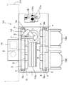
図1は、この発明の局所クリーン化搬送室を有するウエハ検査装置の内部の状態を説明する概略図、図2は、図1の縦断面図、図3は、ミニエンシステムのウエハ検査装置の外観図である。
図3において、20は、ミニエンシステムのウエハ検査装置であって、10は、その局所クリーン化ウエハ搬送室である。局所クリーン化ウエハ搬送室10の上部には、室内に風を送るファンフィルタユニット(FFU)11が装備されていて、その空気吹出し側の前面には空気を浄化するフィルタが設けられている。12a,12bは、13枚あるいは25枚のウエハを収納したポッドであり、FOUPオープナ13a,13bの上に載置される。
なお、ポッド12a,12bは、装置正面側にある開口に機密性の蓋がある。この蓋は、ポッド12a,12bがFOUPオープナ13a,13bに装着されたときにそれぞれのオープナにより開放される。
【0009】
図3におけるポッド12aが載置された装置右側のFOUPオープナ13aは、ウエハロード位置(ロードポート)にあって、装置内部のプリアライメントステージ側に対応している。ポッド12bが載置された左側のFOUPオープナ13bはウエハアンロード位置(アンロードポート)にある。
この局所クリーン化ウエハ搬送室10の内部を示す図1において、14は、ウエハハンドリングユニットであり、検査が終了したウエハを検査ステージ16から取出してポッド12bへと移送する。そして、次の検査ウエハをポッド12aから取出してプリアライメントステージ15へと送り、プリアライメント後にウエハを検査ステージ16へと移送する。なお、14aは、ウエハハンドリングユニットのユニット移動機構(そのガイドレール部分)である。
プリアライメントステージ15は、テーブルにウエハを載置して中心の位置決め(中心出し)とVノッチあるいはオリフラ(OF)の方向の位置決め(θ位置決め)をするステージである。これは、X−Y移動機構を有するX−Yステージ15aと、回転するθステージ15bとを有している。
【0010】
局所クリーン化ウエハ搬送室10の床板1には、FFU11(図2参照)からのエアーを排出する開口として、ウエハハンドリングユニット14のガイドレール14aを挟んで所定の間隔で矩形の開口2,2,…が均等に配列されて前後2列設けられている。そして、この開口2の一部を塞ぐ、移動カバー3,3が2列のそれぞれの開口2をカバーするようこれら開口2に対応して床板1上に設けられている。
図2は、局所クリーン化ウエハ搬送室10の縦断面図である。中央部には、ウエハハンドリングユニット14が設けられている。天井側に設けられたFFU11は、ファン11aとフィルタ11bとからなる。
そして、局所クリーン化ウエハ搬送室10のウエハハンドリングユニット14とプリアライメントステージ15等を制御するコントローラ17がプリアライメントステージ15の下側に設けられている。さらに、局所クリーン化ウエハ搬送室10の床面は、図2に示すように、二重構造になっている。床板1は、筐体5の底面の底板5aに対して上部に位置する床面になっている。この上部にある床板1に所定間隔で開口2が設けられていて、この開口2の上に移動カバー3が設置されている。
その結果、FFU11からのエアー6は、開口2を経て、上部の床板1と底板5aとの間の空間を経て、排気孔7等を介して外部に排出される。
【0011】
図2の下側に示す床板1と移動カバー3との関係の拡大図と図1の平面図に示すように、移動カバー3が床板1の上をスライドするように配置されて、それにより開口2を被う量が調整できるようになっている。言い換えれば、開口2の開口率が移動カバー3により調整される調整機構が形成されている。そのため、移動カバー3の両端には、長孔3a(図1参照)がそれぞれ設けられていて、この長孔3aを貫通して移動カバー3を固定する固定ねじ4が床板1に移動カバー3の両端の位置で螺合している。
そこで、両側の固定ねじ4を緩めて、手動で移動カバー3をスライドさせることで、開口2の開口率が調整できる。最初の開口率は、40%程度に抑えて、低くしておき、エアーの送風量が大きく増加するような制御になっているときには、50%からそれ以上の開口率に増加させる。これによりエアーの送風量の制御が戻り、その風量を大きく増加させなくて済む。なお、エアーの送風量が大きく増加するような制御になっているか否かは、例えば、FFU11のファンの電流あるいは電圧で検出する。
なお、FFU11の風量は、直接風量計で測定してもよく、移動カバー3の調整位置を確認するために、長孔3aの周囲に開口率を示す目盛りを設けておく。
その結果、装置内に風を送るFFU11のダウンフローする風量がこの開口2の開口率を調整することで調整可能になる。
【0012】
また、移動カバー3は床板1に沿って設けられているので、手動ではなく、現在の風量に応じて移動機構により自動的に移動させて風量が増加しないように制御してもよい。この場合には、移動カバー3とこれの移動機構とを床板1の裏側に配置するとよい。それにより、移動機構による発塵の搬送室内への流入の問題は発生しない。
さらに、この実施例では、ウエハハンドリングユニット14のコントローラ17がプリアライメントステージ15の下側に設けられているので、局所クリーン化ウエハ搬送室10は、その内部の凹凸部が少なく、かつ、開口2がウエハハンドリングユニット14のガイドレール14aを挟んで設けられているので、ダウンフローのエアーの流れに乱れが発生し難い。そこで、塵埃が上部に舞い上がり難い構造になる。
【0013】
以上説明してきたが、実施例では、床面の開口を矩形にした例を挙げているが、開口は、矩形に限定されるものではない。
さらに、この発明の局所クリーン化ウエハ搬送室は、図1の実施例では、ウエハ検査装置に使用している例を挙げているが、この発明は、ウエハ検査装置をはじめとして、ウエハ露光装置等、ウエハ処理装置一般に適用できることはもちろんである。さらに、この発明は、このようなウエハ処理装置に限らず、液晶基板をはじめとして各種のワークを搬送する処理装置に適用できる。
【0014】
【発明の効果】
以上の説明のとおり、この発明にあっては、ハンドリングユニットを挟んで搬送室内の床面にFFUからのエアーを排出する開口を多数設けて、この開口の開口率を調整するようにしているので、エアーの送風量が大きく増加するようなときには、送風量を増加させなくても、開口率を増加させることで搬送室の内圧を調整することができる。
その結果、搬送室内の気圧調整が容易でエアーの送風量を大きく増加させなくてもクリーン環境を保持することができる局所クリーン化搬送室および局所クリーン化処理装置を容易に実現することができる。
【図面の簡単な説明】
【図1】図1は、この発明の局所クリーン化搬送室を有するウエハ検査装置の内部の状態を説明する概略図である。
【図2】図2は、図1の縦断面図である。
【図3】図3は、ミニエンシステムのウエハ検査装置の外観図である。
【符号の説明】
1…床板、2…開口、
3…移動カバー、3a…長孔、4…固定ねじ、
5…筐体、5a…底板、6…エアーの流れ、
7…排気孔、10…局所クリーン化ウエハ搬送室、
11…ファンフィルタユニット(FFU)、
12a,12b…ポッド、
13a,13b…FOUPオープナ、
14…ウエハハンドリングユニット、15…プリアライメントステージ、
16…検査ステージ、17…コントローラ、20…ミニエンシステムのウエハ検査装置。[0001]
TECHNICAL FIELD OF THE INVENTION
The present invention relates to a locally-cleaned transfer chamber and a locally-cleaned processing apparatus. More specifically, in a locally-cleaned semiconductor processing apparatus, the pressure in the transfer chamber can be easily adjusted and the clean environment can be reduced without greatly increasing the amount of air blown. The present invention relates to a locally cleaned wafer transfer chamber that can be held.
[0002]
[Prior art]
The quality of a wafer used as a material for a semiconductor IC deteriorates when foreign matter adheres to the surface thereof, and is inspected by an optical foreign matter inspection device. The inspection is performed by a series of operations, and the wafer stored in the wafer cassette is conveyed to, for example, an inspection stage, air-adsorbed to the chuck unit, and rotated.
Therefore, conventionally, a rotation mechanism such as a motor is provided on a wafer pre-alignment stage or inspection stage. The rotation mechanism is used to rotate the wafer to perform angular positioning (θ positioning). In particular, in the case of V-notch positioning, angular positioning and center positioning are performed by a side chuck method in which three points are in contact with the outer periphery of the wafer. (For example, refer to Patent Document 1). However, since the wafer is rotated using a rotating mechanism such as a motor, there is a problem of dusting of metal particles due to sliding of a rotating part.
[0003]
On the other hand, when the wiring pattern formed on the wafer is miniaturized and the process becomes 0.25 μm or more, and the diameter of the wafer becomes a large diameter of about 300 mm, the influence of the foreign matter increases accordingly. To that extent, the yield of the wafer itself and of the chips formed on the wafer is also reduced. Therefore, it is not enough to clean only the room where the conventional semiconductor manufacturing apparatus is installed. No matter how much the cleanliness in the room is increased, there is a limit, so the semiconductor wafer is processed by a local cleaning system, a so-called mini-en system.
The local cleaning device is usually a device with a high degree of sealing, and keeps the inside at a positive pressure to prevent foreign matter from entering from the outside. The degree of cleanliness is reduced to about class 0.01. The internal positive pressure is generated by sending clean air into the inside of the air from a fan through a filter.
The loading and unloading of a workpiece to be processed, such as a wafer, into and out of the apparatus is usually carried out in a sealed pod.The pod is independently closed and tightly mounted on the apparatus, and the lid is closed. An opening mechanism FOUP (FRONT OPENING UNIFIED PAD) is provided (for example, see FIGS. 1 and 8 of Patent Document 2). Further, a wafer transfer device for transferring the wafer, pre-aligning the wafer on the pre-alignment stage, and transferring the wafer to the inspection stage is built therein.
Foreign matter due to dust generated in the wafer transfer device and the pre-alignment stage is discharged from the lower side of the apparatus by clean downflow air discharged from an air cleaning fan filter unit (FFU) provided on the ceiling of the apparatus. (See, for example, FIGS. 3 and 7 of Patent Document 3).
[0004]
[Patent Document 1]
JP-A-4-320043 [Patent Document 2]
JP 2000-173911 A [Patent Document 3]
JP 2000-188320 A
[Problems to be solved by the invention]
The amount of clean downflow air blown out from the air cleaning FFU is controlled so that the pressure in the wafer transfer chamber becomes a constant positive pressure in order to maintain a clean environment.
The locally-cleaned wafer transfer chamber is periodically cleaned, but when the use period is prolonged, the exhaust pressure increases, and the amount of air discharged from the FFU increases in order to keep the pressure in the wafer transfer chamber constant. .
When the amount of air discharged from the FFU is large, clogging of the filter is apt to occur, and dust contained in the filtered air is not sufficiently removed, which causes a reduction in cleanliness. Further, when the amount of air discharged from the FFU increases, the air flow collides with a transport device or the like, disrupting the flow of air, causing foreign matter to stay and flutter. That causes contamination of the wafer.
The object of the present invention has been made in view of the above, and has a local cleaning transfer chamber capable of maintaining a clean environment without easily increasing the air flow rate by easily adjusting the air pressure in the transfer chamber, and An object of the present invention is to provide a local cleaning apparatus.
[0006]
[Means for Solving the Problems]
The feature of the local cleaning transfer chamber and the local cleaning processing apparatus of the present invention for achieving such an object is that air from the fan filter unit is provided on the floor of the local cleaning transfer chamber with the handling unit interposed therebetween. It has a number of openings to be discharged, and an opening ratio adjustment mechanism that covers at least a part of these openings and adjusts the opening ratio.
[0007]
BEST MODE FOR CARRYING OUT THE INVENTION
As described above, in the present invention, a large number of openings for discharging air from the FFU are provided on the floor in the transfer chamber with the handling unit interposed therebetween, and the opening ratio of these openings is adjusted. When the amount of air blow increases greatly, the internal pressure of the transfer chamber can be adjusted by increasing the aperture ratio without increasing the amount of air blow.
As a result, it is possible to easily realize a locally-cleaned transfer chamber and a locally-cleaned processing apparatus capable of easily adjusting the air pressure in the transfer chamber and maintaining a clean environment without greatly increasing the air blowing amount.
[0008]
【Example】
FIG. 1 is a schematic view for explaining an internal state of a wafer inspection apparatus having a local cleaning transfer chamber according to the present invention, FIG. 2 is a longitudinal sectional view of FIG. 1, and FIG. It is an external view.
In FIG. 3,
The
[0009]
The FOUP
In FIG. 1, which shows the inside of the locally cleaned
The
[0010]
Openings for discharging air from the FFU 11 (see FIG. 2) are formed in the
FIG. 2 is a longitudinal sectional view of the locally cleaned
A
As a result, the
[0011]
As shown in the enlarged view of the relationship between the
Therefore, the opening ratio of the
The air volume of the
As a result, the amount of air flowing down the
[0012]
In addition, since the moving
Further, in this embodiment, since the
[0013]
As described above, in the embodiment, the example in which the opening on the floor surface is rectangular has been described, but the opening is not limited to the rectangle.
Further, in the embodiment shown in FIG. 1, the wafer cleaning chamber for local cleaning according to the present invention is used for a wafer inspection apparatus. Of course, the present invention can be applied to a wafer processing apparatus in general. Further, the present invention is not limited to such a wafer processing apparatus, and can be applied to a processing apparatus that transports various works including a liquid crystal substrate.
[0014]
【The invention's effect】
As described above, in the present invention, a large number of openings for discharging air from the FFU are provided on the floor in the transfer chamber with the handling unit interposed therebetween, and the opening ratio of these openings is adjusted. When the amount of air blow increases greatly, the internal pressure of the transfer chamber can be adjusted by increasing the aperture ratio without increasing the amount of air blow.
As a result, it is possible to easily realize the local clean transfer chamber and the local clean processing apparatus that can easily adjust the air pressure in the transfer chamber and maintain the clean environment without greatly increasing the air blowing amount.
[Brief description of the drawings]
FIG. 1 is a schematic diagram illustrating an internal state of a wafer inspection apparatus having a local cleaning transfer chamber according to the present invention.
FIG. 2 is a longitudinal sectional view of FIG.
FIG. 3 is an external view of a wafer inspection apparatus of a mini-en system.
[Explanation of symbols]
1 ... floor board, 2 ... opening,
3 ... moving cover, 3a ... long hole, 4 ... fixing screw,
5 ... housing, 5a ... bottom plate, 6 ... air flow,
7: exhaust hole, 10: locally cleaned wafer transfer chamber,
11 ... Fan filter unit (FFU),
12a, 12b ... pod,
13a, 13b ... FOUP opener,
14: wafer handling unit, 15: pre-alignment stage,
16: inspection stage, 17: controller, 20: mini-en system wafer inspection device.
Claims (5)
前記ハンドリングユニットを挟んで前記所クリーン化搬送室の床面に設けられ前記ファンフィルタユニットからのエアーを排出する多数の開口と、これらの開口の少なくとも一部を被いその開口率を調整する開口率調整機構とを備える局所クリーン化搬送室。In the local clean transfer room that has a handling unit and blows clean air into the room by the fan filter unit to perform local clean,
A large number of openings provided on the floor of the clean transfer chamber with the handling unit interposed therebetween for discharging air from the fan filter unit, and openings for covering at least a part of these openings and adjusting the opening ratio thereof; A local clean transfer chamber equipped with a rate adjustment mechanism.
前記ハンドリングユニットを挟んで前記所クリーン化搬送室の床面に設けられ前記ファンフィルタユニットからのエアーを排出する多数の開口と、これらの開口の少なくとも一部を被いその開口率を調整する開口率調整機構とを備える局所クリーン化処理装置。In the local cleaning processing device having a handling unit and having a local cleaning transfer chamber that blows clean air into the room by the fan filter unit and performs local cleaning,
A large number of openings provided on the floor of the clean transfer chamber with the handling unit interposed therebetween for discharging air from the fan filter unit, and openings for covering at least a part of these openings and adjusting the opening ratio thereof; A local cleaning processing device including a rate adjusting mechanism.
前記ウエハハンドリングユニットを挟んで前記ウエハ搬送室の床面に設けられ前記ファンフィルタユニットからのエアーを排出する多数の開口と、これらの開口の少なくとも一部を被いその開口率を調整する開口率調整機構とを備える局所クリーン化ウエハ処理装置。In a locally-cleaned wafer processing apparatus having a wafer handling unit and having a locally-cleaned wafer transfer chamber that blows clean air into a room by a fan filter unit to locally clean,
Numerous openings provided on the floor of the wafer transfer chamber with the wafer handling unit interposed therebetween for discharging air from the fan filter unit, and an opening ratio for covering at least a part of these openings and adjusting the opening ratio A locally cleaned wafer processing apparatus including an adjustment mechanism.
Priority Applications (1)
| Application Number | Priority Date | Filing Date | Title |
|---|---|---|---|
| JP2002327885A JP4320158B2 (en) | 2002-11-12 | 2002-11-12 | Local cleaning transfer chamber and local cleaning processing equipment |
Applications Claiming Priority (1)
| Application Number | Priority Date | Filing Date | Title |
|---|---|---|---|
| JP2002327885A JP4320158B2 (en) | 2002-11-12 | 2002-11-12 | Local cleaning transfer chamber and local cleaning processing equipment |
Publications (2)
| Publication Number | Publication Date |
|---|---|
| JP2004165331A true JP2004165331A (en) | 2004-06-10 |
| JP4320158B2 JP4320158B2 (en) | 2009-08-26 |
Family
ID=32806344
Family Applications (1)
| Application Number | Title | Priority Date | Filing Date |
|---|---|---|---|
| JP2002327885A Expired - Fee Related JP4320158B2 (en) | 2002-11-12 | 2002-11-12 | Local cleaning transfer chamber and local cleaning processing equipment |
Country Status (1)
| Country | Link |
|---|---|
| JP (1) | JP4320158B2 (en) |
Cited By (4)
| Publication number | Priority date | Publication date | Assignee | Title |
|---|---|---|---|---|
| JP2006186193A (en) * | 2004-12-28 | 2006-07-13 | Nec Electronics Corp | Transfer chamber unit |
| CN100433248C (en) * | 2005-03-31 | 2008-11-12 | 东京毅力科创株式会社 | Substrate processing apparatus |
| JP2012154625A (en) * | 2012-05-24 | 2012-08-16 | Hitachi High-Technologies Corp | Inspection device and mini-environment structure |
| KR102662055B1 (en) | 2021-12-20 | 2024-04-29 | 세메스 주식회사 | Substrate trasnfer module and semiconductor manufacturing equipment |
-
2002
- 2002-11-12 JP JP2002327885A patent/JP4320158B2/en not_active Expired - Fee Related
Cited By (4)
| Publication number | Priority date | Publication date | Assignee | Title |
|---|---|---|---|---|
| JP2006186193A (en) * | 2004-12-28 | 2006-07-13 | Nec Electronics Corp | Transfer chamber unit |
| CN100433248C (en) * | 2005-03-31 | 2008-11-12 | 东京毅力科创株式会社 | Substrate processing apparatus |
| JP2012154625A (en) * | 2012-05-24 | 2012-08-16 | Hitachi High-Technologies Corp | Inspection device and mini-environment structure |
| KR102662055B1 (en) | 2021-12-20 | 2024-04-29 | 세메스 주식회사 | Substrate trasnfer module and semiconductor manufacturing equipment |
Also Published As
| Publication number | Publication date |
|---|---|
| JP4320158B2 (en) | 2009-08-26 |
Similar Documents
| Publication | Publication Date | Title |
|---|---|---|
| JP4553574B2 (en) | Substrate processing method capable of controlling contamination of substrate transfer module | |
| US7722267B2 (en) | Substrate processing apparatus | |
| KR100646515B1 (en) | System and method for coating and developing | |
| US11227784B2 (en) | Thin plate substrate-holding device and transfer robot provided with this holding device | |
| US20070127916A1 (en) | Substrate processing apparatus and substrate processing method | |
| WO2006006377A1 (en) | Substrate processing equipment and method for manufacturing semiconductor device | |
| JPH09260275A (en) | Treatment method and treatment equipment | |
| TW201338014A (en) | Substrate treatment system, substrate delivery method, and computer memory medium | |
| JP2006024638A (en) | Apparatus and method of processing substrate | |
| JP3590328B2 (en) | Coating and developing method and coating and developing system | |
| JP2011205004A (en) | Substrate processing apparatus and substrate processing method | |
| JP4320158B2 (en) | Local cleaning transfer chamber and local cleaning processing equipment | |
| TW201700926A (en) | Substrate transporting device, substrate treating apparatus, and substrate transporting method | |
| JP3283798B2 (en) | Processing equipment | |
| JP2006351864A (en) | Processing system and processing method | |
| JP4709912B2 (en) | Substrate processing method and semiconductor device manufacturing method | |
| JP3662154B2 (en) | Substrate processing system | |
| JP3559219B2 (en) | Coating and developing system and coating and developing method | |
| JP2007036268A (en) | Substrate processing method and substrate processor | |
| JP2001060610A (en) | Substrate transfer device, treating unit, treating system of substrate, transfer method, housing device and housing box | |
| JP2003234341A (en) | Substrate treatment equipment | |
| JP5238331B2 (en) | Substrate processing apparatus and substrate processing system | |
| US20230207359A1 (en) | Humidity control device for equipment front end module of semiconductor processing or characterization tool | |
| JP2979230B2 (en) | Vertical heat treatment equipment | |
| JP2005109513A (en) | Development method and device, and liquid processing method and device |
Legal Events
| Date | Code | Title | Description |
|---|---|---|---|
| A711 | Notification of change in applicant |
Free format text: JAPANESE INTERMEDIATE CODE: A711 Effective date: 20040907 |
|
| A621 | Written request for application examination |
Free format text: JAPANESE INTERMEDIATE CODE: A621 Effective date: 20051110 |
|
| RD02 | Notification of acceptance of power of attorney |
Free format text: JAPANESE INTERMEDIATE CODE: A7422 Effective date: 20051110 |
|
| A977 | Report on retrieval |
Free format text: JAPANESE INTERMEDIATE CODE: A971007 Effective date: 20080428 |
|
| A131 | Notification of reasons for refusal |
Free format text: JAPANESE INTERMEDIATE CODE: A131 Effective date: 20080507 |
|
| A521 | Written amendment |
Free format text: JAPANESE INTERMEDIATE CODE: A523 Effective date: 20080627 |
|
| A131 | Notification of reasons for refusal |
Free format text: JAPANESE INTERMEDIATE CODE: A131 Effective date: 20090210 |
|
| A521 | Written amendment |
Free format text: JAPANESE INTERMEDIATE CODE: A523 Effective date: 20090413 |
|
| TRDD | Decision of grant or rejection written | ||
| A01 | Written decision to grant a patent or to grant a registration (utility model) |
Free format text: JAPANESE INTERMEDIATE CODE: A01 Effective date: 20090512 |
|
| A01 | Written decision to grant a patent or to grant a registration (utility model) |
Free format text: JAPANESE INTERMEDIATE CODE: A01 |
|
| A61 | First payment of annual fees (during grant procedure) |
Free format text: JAPANESE INTERMEDIATE CODE: A61 Effective date: 20090601 |
|
| FPAY | Renewal fee payment (event date is renewal date of database) |
Free format text: PAYMENT UNTIL: 20120605 Year of fee payment: 3 |
|
| R150 | Certificate of patent or registration of utility model |
Free format text: JAPANESE INTERMEDIATE CODE: R150 |
|
| FPAY | Renewal fee payment (event date is renewal date of database) |
Free format text: PAYMENT UNTIL: 20120605 Year of fee payment: 3 |
|
| FPAY | Renewal fee payment (event date is renewal date of database) |
Free format text: PAYMENT UNTIL: 20130605 Year of fee payment: 4 |
|
| LAPS | Cancellation because of no payment of annual fees |