【0001】
【発明の属する技術分野】
本発明は、乗員の前方を覆うように配設されたウインドスクリーンを車体に着脱可能に取付けるようにした自動二輪車のウインドスクリーン装置に関する。
【0002】
【従来の技術】
自動二輪車では、走行風を遮蔽するために乗員の前方にウインドスクリーンを配設する場合がある。このようなウインドスクリーンを車体に取付けるにあたっては、従来、ウインドスクリーンを操向ハンドルにブラケットを介してボルト締め固定したり,あるいはヘッドライトにブラケットを介してボルト締め固定するのが一般的である(例えば、特許文献1,2参照)。
【0003】
【特許文献1】
特開平5−254471号公報
【0004】
【特許文献2】
特開平8−258772号公報
【0005】
【発明が解決しようとする課題】
ところで上記ウインドスクリーンを備える場合、一般道路を走行するのか高速道路を走行するのかにより、あるいはライダの気分によりウインドスクリーンを着脱したいという要請がある。しかしながら上記従来装置では、着脱を容易にするといったことはあまり考慮されておらず、ウインドスクリーンを着脱するには工具を用いてボルトを締め付けたり,弛めたりするといった手間のかかる作業を必要とするという問題がある。
【0006】
本発明は、上記従来の状況に鑑みてなされたもので、工具を用いることなくウインドスクリーンを容易に取り付けたり,取り外したりできる自動二輪車のウインドスクリーン装置を提供することを目的としている。
【0007】
【課題を解決するための手段】
請求項1の発明は、乗員の前方を覆うように配設されたウインドスクリーンを車体に着脱可能に取付けるようにした自動二輪車のウインドスクリーン装置において、上記車体又はウインドスクリーンの何れか一方にダンパ部材を、他方に該ダンパ部材に係合可能のストッパ部を設け、上記車体又はウインドスクリーンの何れか一方にフックを、他方に該フックをロック位置に付勢するロック機構を設け、該ロック機構を、上記フックに係脱可能のアームと、該アームが連結されロック位置とアンロック位置との間で回動可能なレバーとを有する構造のものとし、上記ダンパ部材をストッパ部に係合させるとともに上記アームをフックに係合させて上記レバーをロック位置に回動させることにより上記ウインドスクリーンを車体に固定したことを特徴としている。
【0008】
請求項2の発明は、請求項1において、上記アームはスプリングによりロック方向に付勢されていることを特徴としている。
【0009】
請求項3の発明は、請求項1又は2において、上記レバーには該レバーをロック位置に固定するキーシリンダが配設されていることを特徴としている。
【0010】
請求項4の発明は、請求項3において、上記キーシリンダのキーは車体に配設されたメインスイッチのメインキーが共用されていることを特徴としている。
【0011】
【発明の作用効果】
本発明のウインドスクリーン装置において、ウインドスクリーンを車体側に取り付けるには、ダンパ部材にストッパ部を係合させるとともに、フックにアームを係合させ、この状態でレバーをロック位置に回動する。これによりダンパ部材とストッパ部とがロック機構による引っ張り力でもって固く係合し、ウインドスクリーンは車体に固定されることとなる。またウインドスクリーンを取り外すには、レバーをロック位置からアンロック位置に回動させ、アームをフックから外す。
【0012】
このように請求項1の発明にかかるウインドスクリーン装置によれば、レバーをロック位置とアンロック位置との間で回動させるだけで工具を用いることなく簡単な作業でウインドスクリーンを車体に着脱できる。
【0013】
請求項2の発明では、アームをスプリングでロック方向に付勢したので、ウインドスクリーンをより強固に車体に固定することができ、ウインドスクリーンのがたつきや走行中の振動を防止できる。
【0014】
請求項3の発明では、レバーをロック位置に固定するキーシリンダを配設したので、いたずらや盗難を防止できる。
【0015】
請求項4の発明では、上記キーシリンダのキーをメインスイッチのメインキーと共用したので、余分なキーの携帯を不要にできる。
【0016】
【発明の実施の形態】
以下、本発明の実施の形態を添付図面に基づいて説明する。
【0017】
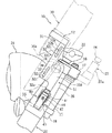
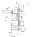
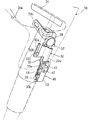
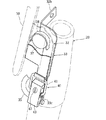
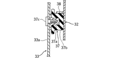
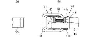
図1ないし図8は、本発明の一実施形態による自動二輪車のウインドスクリーン装置を説明するための図であり、図1はウインドスクリーン装置が配設された自動二輪車の側面図、図2,図3はウインドスクリーン装置の側面図,正面図、図4,図5はウインドスクリーン装置の斜視図、図6はウインドスクリーン装置のゴムダンパの断面図、図7(a),(b)はフック,ロック機構の平面図、図8(a),(b)はフック,ロック機構の側面図である。
【0018】
図において、1は自動二輪車を示しており、これはダブルクレードル型の車体フレーム2内に水冷式4サイクルV型4気筒エンジン3を搭載し、該車体フレーム2の上部に燃料タンク4,シート5を配設した概略構造を有している。
【0019】
上記車体フレーム2の後端下部にはピボット軸6により左右一対のリヤアーム7が上下揺動可能に枢支されており、該リヤアーム7の後端間には後輪8が軸支されている。
【0020】
上記リヤアーム7内にはエンジン動力を後輪8に伝達するドライブシャフト(不図示)が挿入されており、該リヤアーム7と車体フレーム2との間にはリヤサスペンション9が架設されている。
【0021】
上記後輪8の上方にはリヤフェンダ10が配設され、該リヤフェンダ10の上部にはリヤシート11が配設されている。また車体フレーム2の燃料タンク4下方の左右下端部には乗員の足が載置されるフートレストボード12が配置されている。
【0022】
上記車体フレーム2の前端にはヘッドパイプ15が接続されている。このヘッドパイプ15にはステアリングシャフト16が軸受(不図示)を介して回転自在に配設されており、該ステアリングシャフト16の上端及び下端にはそれぞれアッパブラケット17,アンダブラケット18が締結固定されている。この両ブラケット17,18には左右一対のフロントフォーク20が接続固定されており、このフロントフォーク20の下端間には前輪21が軸支されている。
【0023】
上記アッパブラケット17には左右一対のハンドルクラウン22がゴムブッシュ(不図示)を介在させて固定されており、各ハンドルクラウン22には操向ハンドル23がボルト締め固定されている。また上記左右フロントフォーク20の上端部にはヘッドライト24が取付けられており、下部には前輪21の上方を覆うフロントフェンダ25が取付けられている。
【0024】
上記フロントフォーク20の略上半部は円筒状のフォークカバー26により囲まれており、該フォークカバー26は上記アッパ,アンダブラケット17,18に固定されている。またアッパブラケット17の後側にはメインスイッチ27が配設されており、該メインスイッチ27はメインキー28が挿着されるキーシリンダ27aを備えている。
【0025】
上記車体フレーム2の前端部には走行風を遮蔽するウインドスクリーン装置50が配設されており、該ウインドスクリーン装置50はウインドスクリーン30を着脱機構51により車体側に着脱自在とした構造を有している。
【0026】
上記ウインドスクリーン30はポリカーボネート製であり、シート5に着座した乗員の前方を覆う大きさを有している。該ウインドスクリーン30の左右側部は車両後側に湾曲するように形成されており、また下縁部にはヘッドライト24との干渉を回避する凹部30aが切り欠き形成されている。
【0027】
上記着脱機構51は、上記ウインドスクリーン30側に固定されたマウントブラケット52と、車体側に固定されたマウントステー33とをロック機構40でロック,アンロックするように構成されている。
【0028】
上記マウントブラケット52は、上記ウインドスクリーン30の下部に車幅方向に延びる帯板状の横プレート31を配置固定し、該横プレート31の左右端部から左,右の縦プレート32,32をフォークカバー26の車外側面に沿うように下方に延長したものである。
【0029】
上記左,右の縦プレート32の上下に帯板状に延びる支持部32aには上下に延びる長孔が32bが形成され、該長孔32bに挿通したボルト32cにより該縦プレート32,32に上記ウインドシールド30は高さ位置を調整可能に固定されている。
【0030】
上記縦プレート32の、上記支持部32aの下半部に続いて後側に拡がるように一体形成されたベース部32dの車幅方向内側には帯板を半円状に曲げてなるストッパ部38が形成されている。また該ベース部32dの下縁にはフック部32eが下方に延びるように一体形成されており、このフック部32eは下端部を車幅方向外側から上側に向けて曲げて成るJ字形状をなしている。
【0031】
上記マウントステー33は、上記マウントブラケット52の縦プレート32の裏側に配設されている。このマウントステー33は上下方向に延びる帯板状のステー本体33aの上端縁に車内側に屈曲して延びる固定部33bを一体形成してなるもので、該固定部33bは上記アッパブラケット17の前壁にボルト34により締結固定されている。また上記ステー本体33aの下端部33cは車体側に固定された棒部材35に溶接により接合されている。
【0032】
上記ステー本体33aの上部の、上記マウントブラケット52側に形成されたストッパ部38に対応する部位には、円柱状のダンパ部材37が配設されている。このダンパ部材37は、図6に示すように、金属製ボス部37aに硬質ゴムダンパ37bを固着してなるものであり、ボス部37aに螺挿されたボルト37cによりマウントステー33に締結固定されている。
【0033】
そして上記マウントステー33の上記フック部32eの下側にロック機構40が配設されている。このロック機構40は、上記フック部32eに係脱可能のアーム41と、該アーム41の両基部41a,41aが連結ピン42を介して揺動可能に連結されたレバー43とを有している。このレバー43の前端部は上記マウントステー33にボルト締め固定されたベース44に回動ピン45を介してロック位置とアンロック位置との間で回動可能に支持されている。
【0034】
また上記アーム41は棒材を略コ字形状に曲げてなるものであり、該アーム41を軸支する連結ピン42はレバー43に対してtだけ前後方向に移動可能となっている(図8(b)参照)。そして上記両ピン42,45の間にはスプリング46が介在されており、該スプリング46により連結ピン42ひいてはアーム41はロック方向に付勢されている。
【0035】
上記レバー43にはキー挿入部47aを有するキーシリンダ47が配設されている。このキー挿入部47aに上記メインスイッチ27のメインキー28を挿入して施掟することにより、レバー43がロック位置に固定され、回動不能となる。
【0036】
次に本実施形態の作用効果について説明する。
【0037】
ウインドスクリーン30を車体に取り付けるには、ウインドスクリーン30を上方から、左右のストッパ部38がダンパ部材38に係合するように位置させ、この状態でレバー43をアンロック位置に回動させてフック部32eにアーム41を係合させ、レバー43をロック位置に回動させる(図2参照)。
【0038】
これによりダンパ部材37にストッパ部38がロック機構40による引っ張り力でもって固く係合し、ウインドスクリーン30はフロントフォーク20に固定される。またウインドスクリーン30を取り外すには、レバー43をロック位置からアンロック位置に回動させ、アーム41をフック部32eから外し、ウインドスクリーン30を上方に取り外す。
【0039】
このように本実施形態よれば、フロントフォーク20に固定支持されたマントステー33にダンパ部材37を取付けるとともに、ウインドスクリーン30に固定されたマウントブラケット52の縦プレート32にストッパ部38を形成し、さらに上記縦プレート32のフック部32eにアーム41を係合させて下方に引っ張るロック機構40を設けたので、レバー43をアンロック位置とロック位置との間で回動させるだけで、工具を用いることなく簡単な作業でウインドスクリーン30を車体に着脱できる。
【0040】
また上記ダンパ部材37をゴムダンパ37bにより構成するとともに、上記アーム41をスプリング46によりロック方向に付勢したので、ウインドスクリーン30のがたつきを防止でき、走行中にウインドスクリーン30が振動するのを防止できる。
【0041】
本実施形態では、上記レバー43に該レバー43をロック位置に固定するキーシリンダ47を配設したので、いたずらや盗難を防止できる。また上記キーシリンダ47のキー28とメインスイッチ27のメインキー28とを共用したので、余分なキーの携帯を不要にできる。
【図面の簡単な説明】
【図1】本発明の一実施形態によるウインドスクリーン装置が配設された自動二輪車の側面図である。
【図2】上記ウインドスクリーン装置の側面図である。
【図3】上記ウインドスクリーン装置の正面図である。
【図4】上記ウインドスクリーン装置の斜視図である。
【図5】上記ウインドスクリーン装置の斜視図である。
【図6】上記ウインドスクリーン装置のボス部材の断面図である。
【図7】上記ウインドスクリーン装置のフック,ロック機構の図である。
【図8】上記フック,ロック機構の図である。
【符号の説明】
17 アッパブラケット(車体)
26 フォークカバー(車体)
27 メインスイッチ
28 メインキー
30 ウインドスクリーン
32e フック部
37 ダンパ部材
37b ゴムダンパ
38 ストッパ部
40 ロック機構
41 アーム
43 レバー
46 スプリング
47 キーシリンダ[0001]
TECHNICAL FIELD OF THE INVENTION
The present invention relates to a windscreen device for a motorcycle in which a windscreen disposed so as to cover the front of an occupant is detachably attached to a vehicle body.
[0002]
[Prior art]
In some motorcycles, a windscreen may be provided in front of the occupant in order to block traveling wind. Conventionally, when such a windscreen is mounted on a vehicle body, the windscreen is generally fixed to the steering handle with a bolt or a headlight with a bracket. For example, see Patent Documents 1 and 2.
[0003]
[Patent Document 1]
JP-A-5-254471
[Patent Document 2]
JP-A-8-258772
[Problems to be solved by the invention]
By the way, when the above windscreen is provided, there is a demand that the windscreen should be attached / detached depending on whether the vehicle is traveling on a general road or an expressway, or depending on the mood of a rider. However, in the above-mentioned conventional apparatus, easy attachment and detachment is not considered so much, and attaching and detaching the windscreen requires time-consuming work such as tightening and loosening bolts using a tool. There is a problem.
[0006]
The present invention has been made in view of the above-described conventional circumstances, and has as its object to provide a windscreen device for a motorcycle in which a windscreen can be easily attached and detached without using a tool.
[0007]
[Means for Solving the Problems]
According to a first aspect of the present invention, there is provided a motorcycle windscreen device in which a windscreen disposed so as to cover the front of an occupant is detachably attached to a vehicle body, wherein one of the vehicle body and the windscreen has a damper member. A stopper portion engageable with the damper member is provided on the other side, a hook is provided on one of the vehicle body and the windscreen, and a lock mechanism for urging the hook to a lock position is provided on the other side. An arm that can be engaged with and disengaged from the hook, and a lever that is connected to the arm and that can rotate between a locked position and an unlocked position. The windscreen is fixed to the vehicle body by engaging the arm with a hook and rotating the lever to a locked position. It is characterized.
[0008]
According to a second aspect of the present invention, in the first aspect, the arm is urged in a locking direction by a spring.
[0009]
According to a third aspect of the present invention, in the first or second aspect, the lever is provided with a key cylinder for fixing the lever to a lock position.
[0010]
According to a fourth aspect of the present invention, in the third aspect, the key of the key cylinder is shared with a main key of a main switch disposed on the vehicle body.
[0011]
Operation and Effect of the Invention
In the windscreen device of the present invention, to attach the windscreen to the vehicle body, the stopper is engaged with the damper member, the arm is engaged with the hook, and the lever is turned to the lock position in this state. As a result, the damper member and the stopper portion are firmly engaged by the pulling force of the lock mechanism, and the windscreen is fixed to the vehicle body. To remove the windscreen, rotate the lever from the locked position to the unlocked position, and remove the arm from the hook.
[0012]
As described above, according to the windscreen device of the first aspect, the windscreen can be attached to and detached from the vehicle body simply by rotating the lever between the locked position and the unlocked position without using a tool. .
[0013]
According to the second aspect of the present invention, since the arm is urged in the locking direction by the spring, the windscreen can be more firmly fixed to the vehicle body, and the rattling of the windscreen and vibration during running can be prevented.
[0014]
According to the third aspect of the invention, since the key cylinder for fixing the lever at the lock position is provided, it is possible to prevent tampering and theft.
[0015]
According to the fourth aspect of the present invention, since the key of the key cylinder is shared with the main key of the main switch, it is not necessary to carry an extra key.
[0016]
BEST MODE FOR CARRYING OUT THE INVENTION
Hereinafter, embodiments of the present invention will be described with reference to the accompanying drawings.
[0017]
1 to 8 are views for explaining a motorcycle windscreen device according to an embodiment of the present invention. FIG. 1 is a side view of a motorcycle provided with the windscreen device, and FIGS. 3 is a side view and a front view of the wind screen device, FIGS. 4 and 5 are perspective views of the wind screen device, FIG. 6 is a sectional view of a rubber damper of the wind screen device, and FIGS. 7 (a) and (b) are hooks and locks. FIGS. 8A and 8B are plan views of the mechanism, and side views of the hook and lock mechanism.
[0018]
In the figure, reference numeral 1 denotes a motorcycle, which is equipped with a water-cooled four-cycle V-type four-cylinder engine 3 in a double cradle-type body frame 2 and a fuel tank 4 and a seat 5 Is provided.
[0019]
A pair of left and right rear arms 7 are pivotally supported by a pivot shaft 6 at the lower rear end of the body frame 2 so as to be able to swing up and down. A rear wheel 8 is supported between the rear ends of the rear arms 7.
[0020]
A drive shaft (not shown) for transmitting engine power to the rear wheels 8 is inserted into the rear arm 7, and a rear suspension 9 is provided between the rear arm 7 and the vehicle body frame 2.
[0021]
A rear fender 10 is disposed above the rear wheel 8, and a rear seat 11 is disposed above the rear fender 10. A footrest board 12 on which the feet of the occupant are placed is disposed at the lower left and right lower portions of the body frame 2 below the fuel tank 4.
[0022]
A head pipe 15 is connected to a front end of the body frame 2. A steering shaft 16 is rotatably disposed on the head pipe 15 via a bearing (not shown). An upper bracket 17 and an under bracket 18 are fastened and fixed to the upper and lower ends of the steering shaft 16, respectively. I have. A pair of left and right front forks 20 are connected and fixed to the brackets 17 and 18, and a front wheel 21 is supported between lower ends of the front forks 20.
[0023]
A pair of left and right handle crowns 22 are fixed to the upper bracket 17 via rubber bushes (not shown), and a steering handle 23 is fixed to each handle crown 22 by bolting. A headlight 24 is attached to an upper end of the left and right front forks 20, and a front fender 25 that covers an upper part of the front wheel 21 is attached to a lower portion.
[0024]
A substantially upper half of the front fork 20 is surrounded by a cylindrical fork cover 26, and the fork cover 26 is fixed to the upper and the lower brackets 17, 18. A main switch 27 is provided on the rear side of the upper bracket 17, and the main switch 27 includes a key cylinder 27a into which a main key 28 is inserted.
[0025]
At the front end of the vehicle body frame 2, a wind screen device 50 for shielding traveling wind is provided. The wind screen device 50 has a structure in which the wind screen 30 can be detachably attached to the vehicle body by an attachment / detachment mechanism 51. ing.
[0026]
The windscreen 30 is made of polycarbonate and has a size to cover the front of the occupant sitting on the seat 5. The left and right sides of the wind screen 30 are formed so as to curve toward the rear of the vehicle, and the lower edge is formed with a cutout 30a for avoiding interference with the headlight 24.
[0027]
The attachment / detachment mechanism 51 is configured to lock and unlock a mount bracket 52 fixed to the windscreen 30 side and a mount stay 33 fixed to the vehicle body by a lock mechanism 40.
[0028]
The mount bracket 52 has a band-shaped horizontal plate 31 extending in the vehicle width direction disposed and fixed below the windscreen 30, and forks left and right vertical plates 32, 32 from left and right ends of the horizontal plate 31. The cover 26 extends downward along the vehicle outer surface.
[0029]
A vertically extending long hole 32b is formed in a support portion 32a extending in the shape of a strip above and below the left and right vertical plates 32, and the vertical plates 32, 32 are formed on the vertical plates 32, 32 by bolts 32c inserted into the long holes 32b. The windshield 30 is fixed so that the height position can be adjusted.
[0030]
A stopper portion 38 formed by bending a band plate in a semi-circular shape inside a base portion 32d integrally formed so as to extend rearward following the lower half portion of the support portion 32a of the vertical plate 32. Is formed. A hook portion 32e is formed integrally with the lower edge of the base portion 32d so as to extend downward. The hook portion 32e has a J-shape formed by bending a lower end portion upward from the outside in the vehicle width direction. ing.
[0031]
The mount stay 33 is disposed on the back side of the vertical plate 32 of the mount bracket 52. The mount stay 33 is formed by integrally forming a fixed portion 33b which is bent inwardly and extends to the inside of the vehicle at an upper end edge of a strip-shaped stay main body 33a extending in the vertical direction, and the fixed portion 33b is provided in front of the upper bracket 17. It is fastened and fixed to the wall by bolts 34. The lower end 33c of the stay body 33a is welded to a bar member 35 fixed to the vehicle body.
[0032]
A columnar damper member 37 is disposed at a position corresponding to the stopper 38 formed on the mount bracket 52 side on the upper portion of the stay body 33a. As shown in FIG. 6, the damper member 37 is formed by fixing a hard rubber damper 37b to a metal boss 37a, and is fastened and fixed to the mount stay 33 by a bolt 37c screwed into the boss 37a. I have.
[0033]
A lock mechanism 40 is provided below the hook portion 32e of the mount stay 33. The lock mechanism 40 has an arm 41 that can be engaged with and disengaged from the hook portion 32e, and a lever 43 to which both base portions 41a of the arm 41 are swingably connected via a connecting pin 42. . The front end of the lever 43 is rotatably supported between a locked position and an unlocked position via a rotation pin 45 on a base 44 fixed to the mount stay 33 with bolts.
[0034]
The arm 41 is formed by bending a bar into a substantially U-shape, and a connecting pin 42 that supports the arm 41 is movable in the front-rear direction by t with respect to the lever 43 (FIG. 8). (B)). A spring 46 is interposed between the pins 42 and 45. The spring 46 urges the connecting pin 42 and thus the arm 41 in the locking direction.
[0035]
The lever 43 is provided with a key cylinder 47 having a key insertion portion 47a. By inserting the main key 28 of the main switch 27 into the key insertion portion 47a and applying a rule, the lever 43 is fixed at the lock position and cannot rotate.
[0036]
Next, the operation and effect of the present embodiment will be described.
[0037]
In order to attach the windscreen 30 to the vehicle body, the windscreen 30 is positioned from above so that the left and right stoppers 38 engage the damper member 38, and in this state, the lever 43 is turned to the unlock position and the hook is rotated. The arm 41 is engaged with the portion 32e, and the lever 43 is rotated to the lock position (see FIG. 2).
[0038]
As a result, the stopper portion 38 is firmly engaged with the damper member 37 by the pulling force of the lock mechanism 40, and the windscreen 30 is fixed to the front fork 20. To remove the windscreen 30, the lever 43 is rotated from the locked position to the unlocked position, the arm 41 is removed from the hook 32e, and the windscreen 30 is removed upward.
[0039]
As described above, according to the present embodiment, the damper member 37 is attached to the mantle stay 33 fixed and supported by the front fork 20, and the stopper portion 38 is formed on the vertical plate 32 of the mount bracket 52 fixed to the wind screen 30. Further, since the lock mechanism 40 for engaging the arm 41 with the hook portion 32e of the vertical plate 32 and pulling the arm 41 downward is provided, the tool is used only by rotating the lever 43 between the unlock position and the lock position. The windscreen 30 can be attached to and detached from the vehicle body with a simple operation without any trouble.
[0040]
Further, since the damper member 37 is constituted by the rubber damper 37b, and the arm 41 is urged in the locking direction by the spring 46, it is possible to prevent the wind screen 30 from rattling and prevent the wind screen 30 from vibrating during traveling. Can be prevented.
[0041]
In the present embodiment, since the key cylinder 47 for fixing the lever 43 to the lock position is disposed on the lever 43, mischief or theft can be prevented. Further, since the key 28 of the key cylinder 47 and the main key 28 of the main switch 27 are shared, it is not necessary to carry extra keys.
[Brief description of the drawings]
FIG. 1 is a side view of a motorcycle provided with a windscreen device according to an embodiment of the present invention.
FIG. 2 is a side view of the wind screen device.
FIG. 3 is a front view of the wind screen device.
FIG. 4 is a perspective view of the wind screen device.
FIG. 5 is a perspective view of the wind screen device.
FIG. 6 is a sectional view of a boss member of the windscreen device.
FIG. 7 is a view of a hook and lock mechanism of the windscreen device.
FIG. 8 is a view of the hook and lock mechanism.
[Explanation of symbols]
17 Upper bracket (body)
26 Fork cover (body)
27 Main switch 28 Main key 30 Windscreen 32e Hook portion 37 Damper member 37b Rubber damper 38 Stopper portion 40 Lock mechanism 41 Arm 43 Lever 46 Spring 47 Key cylinder

