JP2004136722A - Cooling device for working vehicle - Google Patents
Cooling device for working vehicle Download PDFInfo
- Publication number
- JP2004136722A JP2004136722A JP2002301264A JP2002301264A JP2004136722A JP 2004136722 A JP2004136722 A JP 2004136722A JP 2002301264 A JP2002301264 A JP 2002301264A JP 2002301264 A JP2002301264 A JP 2002301264A JP 2004136722 A JP2004136722 A JP 2004136722A
- Authority
- JP
- Japan
- Prior art keywords
- engine
- radiator
- air
- oil cooler
- cooling fan
- Prior art date
- Legal status (The legal status is an assumption and is not a legal conclusion. Google has not performed a legal analysis and makes no representation as to the accuracy of the status listed.)
- Pending
Links
Images


Classifications
-
- B—PERFORMING OPERATIONS; TRANSPORTING
- B60—VEHICLES IN GENERAL
- B60H—ARRANGEMENTS OF HEATING, COOLING, VENTILATING OR OTHER AIR-TREATING DEVICES SPECIALLY ADAPTED FOR PASSENGER OR GOODS SPACES OF VEHICLES
- B60H1/00—Heating, cooling or ventilating [HVAC] devices
- B60H1/00271—HVAC devices specially adapted for particular vehicle parts or components and being connected to the vehicle HVAC unit
- B60H1/00285—HVAC devices specially adapted for particular vehicle parts or components and being connected to the vehicle HVAC unit for vehicle seats
-
- B—PERFORMING OPERATIONS; TRANSPORTING
- B60—VEHICLES IN GENERAL
- B60H—ARRANGEMENTS OF HEATING, COOLING, VENTILATING OR OTHER AIR-TREATING DEVICES SPECIALLY ADAPTED FOR PASSENGER OR GOODS SPACES OF VEHICLES
- B60H1/00—Heating, cooling or ventilating [HVAC] devices
- B60H1/00357—Air-conditioning arrangements specially adapted for particular vehicles
- B60H1/00378—Air-conditioning arrangements specially adapted for particular vehicles for tractor or load vehicle cabins
-
- B—PERFORMING OPERATIONS; TRANSPORTING
- B60—VEHICLES IN GENERAL
- B60H—ARRANGEMENTS OF HEATING, COOLING, VENTILATING OR OTHER AIR-TREATING DEVICES SPECIALLY ADAPTED FOR PASSENGER OR GOODS SPACES OF VEHICLES
- B60H1/00—Heating, cooling or ventilating [HVAC] devices
- B60H1/00457—Ventilation unit, e.g. combined with a radiator
-
- B—PERFORMING OPERATIONS; TRANSPORTING
- B60—VEHICLES IN GENERAL
- B60H—ARRANGEMENTS OF HEATING, COOLING, VENTILATING OR OTHER AIR-TREATING DEVICES SPECIALLY ADAPTED FOR PASSENGER OR GOODS SPACES OF VEHICLES
- B60H1/00—Heating, cooling or ventilating [HVAC] devices
- B60H1/24—Devices purely for ventilating or where the heating or cooling is irrelevant
-
- B—PERFORMING OPERATIONS; TRANSPORTING
- B60—VEHICLES IN GENERAL
- B60H—ARRANGEMENTS OF HEATING, COOLING, VENTILATING OR OTHER AIR-TREATING DEVICES SPECIALLY ADAPTED FOR PASSENGER OR GOODS SPACES OF VEHICLES
- B60H1/00—Heating, cooling or ventilating [HVAC] devices
- B60H1/32—Cooling devices
- B60H1/3204—Cooling devices using compression
- B60H1/3232—Cooling devices using compression particularly adapted for load transporting vehicles
-
- B—PERFORMING OPERATIONS; TRANSPORTING
- B60—VEHICLES IN GENERAL
- B60H—ARRANGEMENTS OF HEATING, COOLING, VENTILATING OR OTHER AIR-TREATING DEVICES SPECIALLY ADAPTED FOR PASSENGER OR GOODS SPACES OF VEHICLES
- B60H1/00—Heating, cooling or ventilating [HVAC] devices
- B60H1/00271—HVAC devices specially adapted for particular vehicle parts or components and being connected to the vehicle HVAC unit
- B60H2001/003—Component temperature regulation using an air flow
Abstract
Description
【0001】
【発明の属する技術分野】
本発明は、作業車両のオペシートを冷却するための冷却装置に関する。
【0002】
【従来の技術】
従来から、作業車両のオペシートがエンジンからの熱によって加熱されるのを防ぐための技術が知られている(例えば特許文献1)。
上記特許文献1に係る作業車両の側面断面図を、図6に示す。図6によれば、作業車両の後方に設置したカウンタウェイト91内に冷却風の通過する通路92を設け、冷却ファン18によってこの通路92から外気を吸い込んでいる。そして、吸い込んだ外気の空気流93をラジエータ20に通し、ラジエータ20の内部を通る冷却水を冷却している。
【0003】
空気流93は、ラジエータ20を通過することによって熱せられ、エンジンルーム17に入る。この空気流93を、ブロア96によってダクト内に吸い込み、エンジンルーム17上方に配置された、冷凍サイクルのエバポレータ94を通過させる。
【0004】
これにより、空気流は冷却されて冷風95A,95Bとなる。冷風の一部95Aは、オペシート14の後部に吹きつけられ、オペシート14が熱くなるのを防止している。また、冷風の他の一部95Bは、エンジンルーム17内に戻されてエンジンルーム17内を冷却する。
【0005】
【特許文献1】
実開昭58−65123号
【0006】
【発明が解決しようとする課題】
しかしながら、前記特許文献1に開示された従来技術には、次に述べるような問題がある。即ち、従来技術によれば、外部から吸い込んだ空気流は、すべてラジエータ20に通って加熱された後で、エバポレータ94で再冷却されている。従って、再冷却のためにエネルギーを別途必要とし、エネルギーの消費量が大きくなってしまう。
【0007】
しかも、ラジエータ20で加熱された空気流を、一度エンジンルーム17に入れ、これを、ブロア96でエバポレータ94に通すようにしている。そのため、ブロア96を別途必要とするのに加え、空気流の通過する経路が複雑で、製作が困難であるといった問題がある。
【0008】
本発明は、上記の問題に着目してなされたものであり、簡単な構造でエネルギーの消費量が小さく、しかもエンジンの熱によるオペシートへの加熱が小さな作業車両用冷却装置を提供することを目的としている。
【0009】
【課題を解決するための手段、作用及び効果】
上記の目的を達成するために、本発明は、
エンジンの出力によって駆動される冷却ファンと、
冷却ファンによって起こされた空気流を、ラジエータ及びオイルクーラーのどちらをも通過させずにエンジンとオペシートとの間に流す流路とを備えている。
これにより、ラジエータやオイルクーラーを通らない空気流が、エンジンとオペシートとの間を通るので、エンジンの熱が遮られ、オペシートの過熱が防止される。
【0010】
また本発明の作業車両用冷却装置は、
前記流路が、ラジエータ及びオイルクーラーの少なくともいずれか一方と、オペシートとの間に設けられた空気取入口である。
これにより、別途流路を形成することもなく、簡単な構成でオペシートの熱遮蔽が実現できる。
【0011】
また本発明の作業車両用冷却装置は、
前記冷却ファンが吸込式である。
吐き出し式にすると、エンジンルーム内でエンジンの熱によって温められた空気が、オペシートの下方を通ることになる。これに対し、吸込式においては温度の低い外気がオペシートの下方を通るので、オペシートの温度がより低くなる。
【0012】
【発明の実施の形態】
以下、図を参照しながら、本発明に係る実施形態を詳細に説明する。
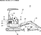
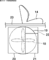
図1は、実施形態に係る油圧ショベル11の側面図、図2は、図1に示した油圧ショベル11の上部旋回体の一部分の平面図、図3は、図1のA−A視平面断面図、図4は、図2のB−B視側面断面図、図5は、図2のC−C視正面断面図を、それぞれ示している。
【0013】
図1において油圧ショベル11は、下部走行体12と、その上部に搭載された旋回自在の上部旋回体13とを備えている。上部旋回体13にはオペシート14が搭載され、その前方には、ブーム24、アーム25、及びアーム25の先端に取着されたバケット26を有する作業機15が、鉛直面内で上下方向に揺動自在に取着されている。
【0014】
オペシート14は、エンジン16を囲繞したエンジンルーム17の上方に設置されている(図1、図3参照)。エンジン16の出力軸には、吸い込み型の冷却ファン18が直結され、外部の空気をエンジン16側に吸い込むようになっている。冷却ファン18の周囲には、円形の開口部を有するシュラウド19が設けられている。
【0015】
冷却ファン18の上流側(外側)には、冷却水を冷却するラジエータ20と、エンジン16オイルを冷却するオイルクーラー21とが、並列に設置されている。オイルクーラー21の高さは、ラジエータ20の高さよりも低く形成されており、オイルクーラー21の上方には、空気が通過する空気取入口22が設けられている。
【0016】
エンジン16が動作して冷却ファン18が回転すると、空気流29が発生する。空気流29の一部は、ラジエータ20及びオイルクーラー21を通過して、エンジンルーム17に向けて吸い込まれる。また、他の一部は、空気取入口22を通って、エンジンルーム17に吸い込まれる。
【0017】
ラジエータ20及びオイルクーラー21を通過する空気流28により、ラジエータ20の内部を通る冷却水、及びオイルクーラー21の内部を通る作動油が冷却される。これにより、空気流28は熱せられ、温度の高い熱風となっている。
【0018】
一方、冷却ファン18によって起こされた空気流29のうち、空気取入口22を通る成分27は、ラジエータ20及びオイルクーラー21を通らず、じかにエンジンルーム17に吸い込まれる。そのため、空気流27は、外気の空気流29と略同様の、空気流28に比べて低い温度となっている。
【0019】
このとき、空気取入口22が、オペシート14の直下に設けられているため、温度の低い空気流27は、オペシート14の直下を略水平に通過する(図5参照)。その結果、エンジン16とオペシート14との間を、温度の低い空気流27がエアカーテン状に通過することになるので、エンジン16の熱がオペシート14に伝わりにくくなって、オペシート14が低い温度に保たれる。
【0020】
尚、オペシート14の下部には、防振材23が貼着されており、この防振材23は、断熱効果をも有している。これにより、エンジン16の熱が、一層オペシート14に伝わりにくくなっている。
従って、オペシート14に着席したオペレータが、熱による不快感を感じることが少なく、快適な状態で作業を行なうことが可能である。
【0021】
以上説明したように本発明によれば、空気取入口22を設け、冷却ファン18によって起こされた空気流が、ラジエータ20やオイルクーラー21を通らずに、オペシート14とエンジン16との間を通過するようにしている。その結果、オペシート14とエンジン16との間に、ラジエータ20やオイルクーラー21を通らない、比較的温度の低い空気流27が通過する、空気の流路が生まれる。この空気流27がエンジン16からの熱を遮るので、オペシート14が熱せられることが少なく、快適な運転操作が可能である。
【0022】
尚、上記の説明においては、オペシート14がエンジン16の上方に配置された場合について説明したが、これに限られるものではない。例えば、オペシート14がエンジン16の前方にあるような場合においても、冷却ファン18の空気流の一部27が、オイルクーラー21やラジエータ20を通らずに、エンジン16とオペシート14との間を通るようにすればよい。
【0023】
また、冷却ファン18は、エンジン16の出力軸に直結であるように説明したが、例えばベルトドライブ等によって、間接的に駆動されてもよい。
さらには、オイルクーラー21の上方に空気取入口22を設けるようにしたが、これに限られるものではない。例えばラジエータ20の背をより低くして、ラジエータ20とオペシート14との間に設けてもよく、ラジエータ20及びオペシート14の、両方の上方に設けてもよい。また、ラジエータ20やオペシート14の一部を切り欠いたような形状として、そこを空気取入口22としてもよい。
【0024】
また、冷却ファン18が吸込式である場合について説明したが、これに限られるものではない。冷却ファン18が吐き出し型の場合には、冷却ファン18から吐き出される空気流は、吸込式の場合と同様に、一部28がラジエータ20やオイルクーラー21を通り、他の一部27が空気取入口22を通る。この成分27は、やはりラジエータ20やオイルクーラー21を通っていないので、さほど熱せられてはいない。
【0025】
このとき、空気取入口22の抵抗が小さいので、空気取入口22を通る成分27の風量は、ラジエータ20やオイルクーラー21を通る成分28に比べて、多くなる。従って、このような空気取入口22を通る成分27が、エンジン16とオペシート14との間をより多く通るので、やはりエアカーテンのようになって、オペシート14にエンジン16の熱が伝わりにくくなり、快適な運転が可能である。
【0026】
また、実施形態において、作業機15は、水平面内で左右方向に揺動自在に取着されているが、本発明はこのような形態に限られるものではない。さらには、油圧ショベルに限られるものではなく、小型の建設機械やフォークリフトに対しても、応用が可能である。
【図面の簡単な説明】
【図1】実施形態に係る油圧ショベルの側面図。
【図2】実施形態に係る油圧ショベルの上部旋回体の一部分の平面図。
【図3】図1のA−A視平面断面図。
【図4】図2のB−B視側面断面図。
【図5】図2のC−C視正面断面図。
【図6】従来技術に係る作業車両の側面断面図。
【符号の説明】
11:油圧ショベル11、12:下部走行体12、13:上部旋回体13、14:オペシート14、15:作業機15、16:エンジン16、17:エンジンルーム17、18:冷却ファン18、19:シュラウド19、20:ラジエータ20、21:オイルクーラー21、22:空気取入口22、23:防振材23、24:ブーム、25:アーム、26:バケット、27:空気流、28:空気流、29:空気流。[0001]
TECHNICAL FIELD OF THE INVENTION
The present invention relates to a cooling device for cooling an operation seat of a work vehicle.
[0002]
[Prior art]
BACKGROUND ART Conventionally, a technique for preventing an operation seat of a work vehicle from being heated by heat from an engine is known (for example, Patent Document 1).
FIG. 6 shows a side cross-sectional view of the work vehicle according to
[0003]
The
[0004]
As a result, the airflow is cooled and becomes the
[0005]
[Patent Document 1]
No. 58-65123 [0006]
[Problems to be solved by the invention]
However, the conventional technique disclosed in
[0007]
In addition, the air flow heated by the
[0008]
SUMMARY OF THE INVENTION The present invention has been made in view of the above problems, and has as its object to provide a cooling device for a work vehicle that has a simple structure, consumes a small amount of energy, and has a small heating of an operation sheet by heat of an engine. And
[0009]
Means for Solving the Problems, Functions and Effects
In order to achieve the above object, the present invention provides:
A cooling fan driven by the output of the engine;
A flow path is provided for flowing the air flow generated by the cooling fan between the engine and the operation seat without passing through the radiator and the oil cooler.
Accordingly, the airflow that does not pass through the radiator or the oil cooler passes between the engine and the operation seat, so that heat of the engine is blocked, and overheating of the operation seat is prevented.
[0010]
Further, the cooling device for a working vehicle of the present invention,
The flow path is an air intake provided between at least one of the radiator and the oil cooler and the operation sheet.
Thereby, the heat shielding of the operation sheet can be realized with a simple configuration without forming a separate flow path.
[0011]
Further, the cooling device for a working vehicle of the present invention,
The cooling fan is a suction fan.
In the case of the discharge type, the air heated by the heat of the engine in the engine room passes below the operation sheet. On the other hand, in the suction type, since the low-temperature outside air passes below the operation sheet, the temperature of the operation sheet becomes lower.
[0012]
BEST MODE FOR CARRYING OUT THE INVENTION
Hereinafter, embodiments of the present invention will be described in detail with reference to the drawings.
FIG. 1 is a side view of a
[0013]
In FIG. 1, a
[0014]
The
[0015]
On the upstream side (outside) of the
[0016]
When the
[0017]
The cooling water passing through the inside of the
[0018]
On the other hand, of the
[0019]
At this time, since the
[0020]
In addition, a
Therefore, the operator seated on the
[0021]
As described above, according to the present invention, the
[0022]
In the above description, the case where the
[0023]
Further, the cooling
Further, the
[0024]
Further, the case where the cooling
[0025]
At this time, since the resistance of the
[0026]
Further, in the embodiment, the working
[Brief description of the drawings]
FIG. 1 is a side view of a hydraulic excavator according to an embodiment.
FIG. 2 is a plan view of a part of the upper swing body of the hydraulic shovel according to the embodiment.
FIG. 3 is a plan sectional view taken along line AA of FIG. 1;
FIG. 4 is a side sectional view taken along line BB of FIG. 2;
FIG. 5 is a front sectional view taken along the line CC of FIG. 2;
FIG. 6 is a side sectional view of a work vehicle according to the related art.
[Explanation of symbols]
11:
Claims (3)
冷却ファン(18)によって起こされた空気流(27)を、ラジエータ(20)及びオイルクーラー(21)のどちらをも通過させずに、エンジン(16)とオペシート(14)との間に流す流路とを備えた
ことを特徴とする作業車両用冷却装置。A cooling fan (18) driven by the output of the engine (16);
The airflow (27) generated by the cooling fan (18) flows between the engine (16) and the operation seat (14) without passing through both the radiator (20) and the oil cooler (21). A cooling device for a working vehicle, comprising: a road;
前記流路が、ラジエータ(20)及びオイルクーラー(21)の少なくともいずれか一方と、オペシート(14)との間に設けられた空気取入口(22)である
ことを特徴とする作業車両用冷却装置。The cooling device for a work vehicle according to claim 1,
The cooling device for a work vehicle, wherein the flow path is an air intake (22) provided between at least one of a radiator (20) and an oil cooler (21) and an operation seat (14). apparatus.
前記冷却ファン(18)が吸込式である
ことを特徴とする作業車両用冷却装置。The cooling device for a work vehicle according to claim 1 or 2,
The cooling device for a work vehicle, wherein the cooling fan (18) is a suction type.
Priority Applications (4)
| Application Number | Priority Date | Filing Date | Title |
|---|---|---|---|
| JP2002301264A JP2004136722A (en) | 2002-10-16 | 2002-10-16 | Cooling device for working vehicle |
| DE60322162T DE60322162D1 (en) | 2002-10-16 | 2003-10-14 | Arrangement for the air conditioning of a work vehicle |
| EP03023271A EP1410930B1 (en) | 2002-10-16 | 2003-10-14 | Work vehicle cooling system |
| US10/683,281 US7047912B2 (en) | 2002-10-16 | 2003-10-14 | Work vehicle cooling system |
Applications Claiming Priority (1)
| Application Number | Priority Date | Filing Date | Title |
|---|---|---|---|
| JP2002301264A JP2004136722A (en) | 2002-10-16 | 2002-10-16 | Cooling device for working vehicle |
Publications (2)
| Publication Number | Publication Date |
|---|---|
| JP2004136722A true JP2004136722A (en) | 2004-05-13 |
| JP2004136722A5 JP2004136722A5 (en) | 2005-04-28 |
Family
ID=32040798
Family Applications (1)
| Application Number | Title | Priority Date | Filing Date |
|---|---|---|---|
| JP2002301264A Pending JP2004136722A (en) | 2002-10-16 | 2002-10-16 | Cooling device for working vehicle |
Country Status (4)
| Country | Link |
|---|---|
| US (1) | US7047912B2 (en) |
| EP (1) | EP1410930B1 (en) |
| JP (1) | JP2004136722A (en) |
| DE (1) | DE60322162D1 (en) |
Cited By (1)
| Publication number | Priority date | Publication date | Assignee | Title |
|---|---|---|---|---|
| JP2015090050A (en) * | 2013-11-07 | 2015-05-11 | コベルコ建機株式会社 | Electrical component arrangement structure of construction machine |
Families Citing this family (3)
| Publication number | Priority date | Publication date | Assignee | Title |
|---|---|---|---|---|
| DE102005035072B4 (en) * | 2005-07-27 | 2020-06-18 | Bayerische Motoren Werke Aktiengesellschaft | Combustion piston engine with an electric actuator for stroke actuation of the gas exchange valves |
| JP4996349B2 (en) * | 2007-05-31 | 2012-08-08 | 株式会社クボタ | Work vehicle cooling structure |
| KR100974278B1 (en) * | 2008-03-18 | 2010-08-06 | 볼보 컨스트럭션 이키프먼트 홀딩 스웨덴 에이비 | engine room of construction equipment |
Family Cites Families (23)
| Publication number | Priority date | Publication date | Assignee | Title |
|---|---|---|---|---|
| DE1580826A1 (en) * | 1966-01-27 | 1971-11-11 | Se Fahrzeugwerke Gmbh | Device on an explosive-protected vehicle with battery-electric or internal combustion engine drive |
| GB1259993A (en) * | 1969-06-13 | 1972-01-12 | Ch Traktorny Zd | A driver's cab of a vehicle |
| JPS55148607A (en) * | 1979-05-10 | 1980-11-19 | Nissan Motor Co Ltd | Seat cooling device for industrial vehicle |
| JPS5865123A (en) | 1981-10-13 | 1983-04-18 | タイガー魔法瓶株式会社 | Electric jar |
| US4546696A (en) * | 1982-04-05 | 1985-10-15 | Caterpillar Tractor Co. | Wall construction for a vehicle cab |
| US4874036A (en) | 1987-07-14 | 1989-10-17 | Sanden Corporation | Heating and air conditioning system for a forklift |
| US5143516A (en) * | 1989-02-06 | 1992-09-01 | Paccar Inc. | Recirculation shield and fan shroud assembly |
| JPH08151660A (en) | 1994-11-30 | 1996-06-11 | Yanmar Diesel Engine Co Ltd | Back hoe |
| JPH08240653A (en) | 1995-03-03 | 1996-09-17 | Hitachi Ltd | Positional information display equipment |
| JPH08268088A (en) * | 1995-03-31 | 1996-10-15 | Hitachi Constr Mach Co Ltd | Cooling structure of construction equipment |
| JP3238310B2 (en) | 1995-09-29 | 2001-12-10 | 株式会社クボタ | Arrangement structure in the hood of a small backhoe |
| JP3547239B2 (en) | 1995-12-08 | 2004-07-28 | 株式会社クボタ | Turning work machine |
| JPH09247730A (en) | 1996-03-05 | 1997-09-19 | Matsushita Electric Ind Co Ltd | Method and device for position detection |
| JP3294100B2 (en) | 1996-03-29 | 2002-06-17 | 株式会社クボタ | Backhoe |
| JPH10104336A (en) | 1996-09-27 | 1998-04-24 | Mitsui Constr Co Ltd | Moving body management facility and cart management facility in golf course |
| JP3159103B2 (en) | 1997-02-21 | 2001-04-23 | トヨタ自動車株式会社 | Road-to-vehicle communication system |
| JPH10312500A (en) | 1997-05-12 | 1998-11-24 | Mitsubishi Electric Corp | Mobile communication navigation device, and recording medium recorded with display control program thereof |
| JPH117599A (en) | 1997-06-17 | 1999-01-12 | Hitachi Ltd | Incorporated type automobile radio system |
| JPH1181378A (en) | 1997-09-04 | 1999-03-26 | Kubota Corp | Slewing work machine |
| JP3681923B2 (en) * | 1999-06-18 | 2005-08-10 | 株式会社クボタ | Swivel work machine |
| JP4236229B2 (en) * | 1999-10-08 | 2009-03-11 | 株式会社小松製作所 | Sound absorbing blade mounting structure for work vehicle |
| US6431299B1 (en) * | 2000-04-05 | 2002-08-13 | Clark Equipment Company | Cooling air ducting for excavator |
| JP4246360B2 (en) | 2000-08-24 | 2009-04-02 | 日立建機株式会社 | Swivel construction machine |
-
2002
- 2002-10-16 JP JP2002301264A patent/JP2004136722A/en active Pending
-
2003
- 2003-10-14 US US10/683,281 patent/US7047912B2/en not_active Expired - Fee Related
- 2003-10-14 DE DE60322162T patent/DE60322162D1/en not_active Expired - Lifetime
- 2003-10-14 EP EP03023271A patent/EP1410930B1/en not_active Expired - Fee Related
Cited By (1)
| Publication number | Priority date | Publication date | Assignee | Title |
|---|---|---|---|---|
| JP2015090050A (en) * | 2013-11-07 | 2015-05-11 | コベルコ建機株式会社 | Electrical component arrangement structure of construction machine |
Also Published As
| Publication number | Publication date |
|---|---|
| DE60322162D1 (en) | 2008-08-28 |
| EP1410930A1 (en) | 2004-04-21 |
| US20040074454A1 (en) | 2004-04-22 |
| EP1410930B1 (en) | 2008-07-16 |
| US7047912B2 (en) | 2006-05-23 |
Similar Documents
| Publication | Publication Date | Title |
|---|---|---|
| KR100832083B1 (en) | Cooling apparatus of a fuel cell vehicle | |
| JPH08270444A (en) | Cooling structure of construction equipment | |
| JP2009113560A (en) | Air conditioner for vehicle | |
| JP2004136722A (en) | Cooling device for working vehicle | |
| JP2014122496A (en) | Work machine | |
| JP2006291537A (en) | Cooling structure of work machine | |
| JP2004299446A (en) | Heat exchanger for vehicle | |
| JPH0821240A (en) | Outside air introducing controller of engine room | |
| JP2566409B2 (en) | Work vehicle cooling and exhaust structure | |
| JP4110022B2 (en) | Vehicle heat exchanger | |
| JPS59138716A (en) | Engine cooling apparatus | |
| JP4023271B2 (en) | Structure of air conditioner for windows | |
| JP2008296615A (en) | Construction machine | |
| JP2548492Y2 (en) | Engine cooling system | |
| JP2003306046A (en) | Heat exchange device | |
| JP3955945B2 (en) | Blower | |
| KR101744826B1 (en) | Cooling fan unit | |
| JP2002071166A (en) | Air-cooled condenser | |
| KR200184011Y1 (en) | A duct structure for sucking air for cooling a engine system in the heavy equipment | |
| JP2002356115A (en) | Cooling device for construction machine | |
| JP2004291711A (en) | Cooling device of construction machine | |
| JPS63270230A (en) | Cooling and exhausting structure for vehicle | |
| JPH08284660A (en) | Prime moving part cooling device for working vehicle | |
| KR100410783B1 (en) | Heating apparatus for rear passenger space of bus | |
| JPH11208257A (en) | Heat exchanger for vehicle |
Legal Events
| Date | Code | Title | Description |
|---|---|---|---|
| A521 | Written amendment |
Free format text: JAPANESE INTERMEDIATE CODE: A523 Effective date: 20040617 |
|
| A621 | Written request for application examination |
Free format text: JAPANESE INTERMEDIATE CODE: A621 Effective date: 20050608 |
|
| A977 | Report on retrieval |
Free format text: JAPANESE INTERMEDIATE CODE: A971007 Effective date: 20070309 |
|
| A131 | Notification of reasons for refusal |
Free format text: JAPANESE INTERMEDIATE CODE: A131 Effective date: 20070417 |
|
| A521 | Written amendment |
Free format text: JAPANESE INTERMEDIATE CODE: A523 Effective date: 20070618 |
|
| A521 | Written amendment |
Free format text: JAPANESE INTERMEDIATE CODE: A821 Effective date: 20070927 |
|
| A711 | Notification of change in applicant |
Free format text: JAPANESE INTERMEDIATE CODE: A712 Effective date: 20070927 |
|
| A521 | Written amendment |
Free format text: JAPANESE INTERMEDIATE CODE: A821 Effective date: 20071031 |
|
| A131 | Notification of reasons for refusal |
Free format text: JAPANESE INTERMEDIATE CODE: A131 Effective date: 20080115 |
|
| A02 | Decision of refusal |
Free format text: JAPANESE INTERMEDIATE CODE: A02 Effective date: 20080527 |