JP2004108183A - Air-fuel ratio control device for internal combustion engine - Google Patents
Air-fuel ratio control device for internal combustion engine Download PDFInfo
- Publication number
- JP2004108183A JP2004108183A JP2002269342A JP2002269342A JP2004108183A JP 2004108183 A JP2004108183 A JP 2004108183A JP 2002269342 A JP2002269342 A JP 2002269342A JP 2002269342 A JP2002269342 A JP 2002269342A JP 2004108183 A JP2004108183 A JP 2004108183A
- Authority
- JP
- Japan
- Prior art keywords
- fuel ratio
- air
- sensor
- sensor error
- target
- Prior art date
- Legal status (The legal status is an assumption and is not a legal conclusion. Google has not performed a legal analysis and makes no representation as to the accuracy of the status listed.)
- Pending
Links
- 239000000446 fuel Substances 0.000 title claims abstract description 406
- 238000002485 combustion reaction Methods 0.000 title claims description 16
- 239000007789 gas Substances 0.000 claims description 24
- 239000003054 catalyst Substances 0.000 claims description 20
- 238000000746 purification Methods 0.000 claims description 7
- QVGXLLKOCUKJST-UHFFFAOYSA-N atomic oxygen Chemical compound [O] QVGXLLKOCUKJST-UHFFFAOYSA-N 0.000 claims description 6
- 239000001301 oxygen Substances 0.000 claims description 6
- 229910052760 oxygen Inorganic materials 0.000 claims description 6
- 102100022354 FAS-associated factor 2 Human genes 0.000 abstract description 6
- 101000824586 Homo sapiens FAS-associated factor 2 Proteins 0.000 abstract description 6
- 230000002349 favourable effect Effects 0.000 abstract 1
- 238000000034 method Methods 0.000 description 24
- 238000002347 injection Methods 0.000 description 20
- 239000007924 injection Substances 0.000 description 20
- 238000001514 detection method Methods 0.000 description 10
- 230000007423 decrease Effects 0.000 description 5
- 102100027279 FAS-associated factor 1 Human genes 0.000 description 3
- 101000914654 Homo sapiens FAS-associated factor 1 Proteins 0.000 description 3
- 238000010586 diagram Methods 0.000 description 3
- 239000000498 cooling water Substances 0.000 description 2
- 230000000694 effects Effects 0.000 description 2
- 238000011144 upstream manufacturing Methods 0.000 description 2
- 239000002826 coolant Substances 0.000 description 1
- 230000006866 deterioration Effects 0.000 description 1
- 230000006870 function Effects 0.000 description 1
- 239000000203 mixture Substances 0.000 description 1
- 238000001179 sorption measurement Methods 0.000 description 1
- XLYOFNOQVPJJNP-UHFFFAOYSA-N water Substances O XLYOFNOQVPJJNP-UHFFFAOYSA-N 0.000 description 1
Images


Classifications
-
- F—MECHANICAL ENGINEERING; LIGHTING; HEATING; WEAPONS; BLASTING
- F02—COMBUSTION ENGINES; HOT-GAS OR COMBUSTION-PRODUCT ENGINE PLANTS
- F02D—CONTROLLING COMBUSTION ENGINES
- F02D41/00—Electrical control of supply of combustible mixture or its constituents
- F02D41/02—Circuit arrangements for generating control signals
- F02D41/14—Introducing closed-loop corrections
- F02D41/1438—Introducing closed-loop corrections using means for determining characteristics of the combustion gases; Sensors therefor
- F02D41/1444—Introducing closed-loop corrections using means for determining characteristics of the combustion gases; Sensors therefor characterised by the characteristics of the combustion gases
- F02D41/1454—Introducing closed-loop corrections using means for determining characteristics of the combustion gases; Sensors therefor characterised by the characteristics of the combustion gases the characteristics being an oxygen content or concentration or the air-fuel ratio
- F02D41/1456—Introducing closed-loop corrections using means for determining characteristics of the combustion gases; Sensors therefor characterised by the characteristics of the combustion gases the characteristics being an oxygen content or concentration or the air-fuel ratio with sensor output signal being linear or quasi-linear with the concentration of oxygen
-
- F—MECHANICAL ENGINEERING; LIGHTING; HEATING; WEAPONS; BLASTING
- F02—COMBUSTION ENGINES; HOT-GAS OR COMBUSTION-PRODUCT ENGINE PLANTS
- F02D—CONTROLLING COMBUSTION ENGINES
- F02D41/00—Electrical control of supply of combustible mixture or its constituents
- F02D41/24—Electrical control of supply of combustible mixture or its constituents characterised by the use of digital means
- F02D41/2406—Electrical control of supply of combustible mixture or its constituents characterised by the use of digital means using essentially read only memories
- F02D41/2425—Particular ways of programming the data
- F02D41/2429—Methods of calibrating or learning
- F02D41/2441—Methods of calibrating or learning characterised by the learning conditions
-
- F—MECHANICAL ENGINEERING; LIGHTING; HEATING; WEAPONS; BLASTING
- F02—COMBUSTION ENGINES; HOT-GAS OR COMBUSTION-PRODUCT ENGINE PLANTS
- F02D—CONTROLLING COMBUSTION ENGINES
- F02D41/00—Electrical control of supply of combustible mixture or its constituents
- F02D41/24—Electrical control of supply of combustible mixture or its constituents characterised by the use of digital means
- F02D41/2406—Electrical control of supply of combustible mixture or its constituents characterised by the use of digital means using essentially read only memories
- F02D41/2425—Particular ways of programming the data
- F02D41/2429—Methods of calibrating or learning
- F02D41/2451—Methods of calibrating or learning characterised by what is learned or calibrated
- F02D41/2454—Learning of the air-fuel ratio control
-
- F—MECHANICAL ENGINEERING; LIGHTING; HEATING; WEAPONS; BLASTING
- F02—COMBUSTION ENGINES; HOT-GAS OR COMBUSTION-PRODUCT ENGINE PLANTS
- F02D—CONTROLLING COMBUSTION ENGINES
- F02D41/00—Electrical control of supply of combustible mixture or its constituents
- F02D41/24—Electrical control of supply of combustible mixture or its constituents characterised by the use of digital means
- F02D41/2406—Electrical control of supply of combustible mixture or its constituents characterised by the use of digital means using essentially read only memories
- F02D41/2425—Particular ways of programming the data
- F02D41/2429—Methods of calibrating or learning
- F02D41/2451—Methods of calibrating or learning characterised by what is learned or calibrated
- F02D41/2474—Characteristics of sensors
-
- F—MECHANICAL ENGINEERING; LIGHTING; HEATING; WEAPONS; BLASTING
- F02—COMBUSTION ENGINES; HOT-GAS OR COMBUSTION-PRODUCT ENGINE PLANTS
- F02D—CONTROLLING COMBUSTION ENGINES
- F02D41/00—Electrical control of supply of combustible mixture or its constituents
- F02D41/02—Circuit arrangements for generating control signals
- F02D41/04—Introducing corrections for particular operating conditions
- F02D41/12—Introducing corrections for particular operating conditions for deceleration
- F02D41/123—Introducing corrections for particular operating conditions for deceleration the fuel injection being cut-off
- F02D41/126—Introducing corrections for particular operating conditions for deceleration the fuel injection being cut-off transitional corrections at the end of the cut-off period
Landscapes
- Engineering & Computer Science (AREA)
- Chemical & Material Sciences (AREA)
- Combustion & Propulsion (AREA)
- Mechanical Engineering (AREA)
- General Engineering & Computer Science (AREA)
- Analytical Chemistry (AREA)
- Electrical Control Of Air Or Fuel Supplied To Internal-Combustion Engine (AREA)
- Combined Controls Of Internal Combustion Engines (AREA)
Abstract
Description
【0001】
【発明の属する技術分野】
本発明は、内燃機関の排出ガスの空燃比を検出する空燃比センサの出力の誤差を学習する機能を備えた内燃機関の空燃比制御装置に関するものである。
【0002】
【従来の技術】
近年、車両に搭載される内燃機関においては、排出ガスの目標空燃比を三元触媒等の触媒の浄化ウインドである理論空燃比付近に設定し、空燃比センサで検出した排出ガスの空燃比を目標空燃比に一致させるように空燃比をフィードバック制御することで、触媒の排出ガス浄化効率を高めるようにしている。
【0003】
また、近年の車両は、減速運転時等に燃料噴射を停止する燃料カットを行って燃費を向上させるようにしているが、この燃料カット中には、吸入空気が燃焼せずにエンジンから排気管内に排出されるため、未燃焼の排出ガス中の酸素が触媒に多量に吸着された状態となる。このため、燃料カット終了後に、排出ガスの空燃比を通常の目標空燃比である理論空燃比付近にフィードバック制御しても、燃料カット中に触媒に吸着された多量の酸素によって触媒本来の浄化能力を得ることができない。
【0004】
そこで、近年の車両は、燃料カット終了後に、一時的に目標空燃比を理論空燃比よりもリッチ方向にシフトして、排出ガスの空燃比を理論空燃比よりもリッチに制御するリッチ制御を行うことで、触媒に吸着された酸素を排出ガス中のHCと反応させて除去し、触媒本来の浄化能力を回復させるようにしている。
【0005】
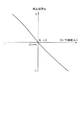
一般に、図2に示すように、空燃比センサの出力特性は、理論空燃比(空気過剰率λ=1)付近では標準出力特性に対する誤差(公差)がほぼ0になって高精度な空燃比検出が可能であるが、理論空燃比から離れるほど標準出力特性に対する検出誤差が大きくなって検出精度が低下するという特性をもっている。このため、上述した燃料カット終了後のリッチ制御時に、排出ガスの空燃比を理論空燃比よりもリッチな目標空燃比λtgにフィードバック制御しても、そのリッチ空燃比領域における空燃比センサの検出精度が悪いために、排出ガスの空燃比をリッチ制御時の目標空燃比λtgに精度良く制御することができない。その結果、排出ガスの実空燃比λr がリッチ制御時の目標空燃比λtgよりもリッチ側にずれて、CO、HC等のリッチ成分排出量が増加したり、或は、排出ガスの実空燃比λr がリッチ制御時の目標空燃比λtgよりもリーン側にずれてNOx排出量が増加してしまう可能性がある。
【0006】
そこで、空燃比センサの出力の誤差を補償する技術として、例えば、特許文献1(特開平9−203343号公報)に記載されているように、燃料カット開始から所定時間が経過するまでの空燃比センサの出力の変化特性(傾き特性)を学習して、その変化特性を予め定めた基準の変化特性(傾き特性)と比較して補正データを作成し、この補正データにより空燃比センサの出力を補正するようにしたものがある。
【0007】
また、特許文献2(特許第2503381号公報)に記載されているように、特定の運転状態(例えば低中負荷の定常運転状態)のときに空燃比センサの実限界電流を検出して、その実限界電流(検出空燃比)と予め特定の運転状態に対応して記憶されている目標限界電流(目標空燃比)との偏差を算出し、この偏差に基づいて補正係数を算出して、この補正係数により空燃比センサの出力を補正するようにしたものがある。
【0008】
【特許文献1】
特開平9−203343号公報(第2頁等)
【特許文献2】
特許第2503381号公報(第2頁等)
【0009】
【発明が解決しようとする課題】
特許文献1のセンサ出力補正方法では、燃料カット開始後の空燃比センサの出力の変化特性を学習するようにしているが、燃料カット開始後の空燃比センサの出力の変化特性は、空燃比センサの出力の誤差以外の要因(例えば排出ガス流量、燃料カット開始当初の触媒のリーン/リッチ成分の吸着状態や劣化度合等)によっても変化するため、燃料カット開始後の空燃比センサの出力の変化特性を測定しても、空燃比センサの出力の誤差を精度良く学習することができず、空燃比センサの出力の補正精度が悪いという欠点がある。
【0010】
また、特許文献2のセンサ出力補正方法では、特定の運転状態のときの空燃比センサの実限界電流(検出空燃比)と予め記憶した目標限界電流(目標空燃比)との偏差に基づいて補正係数を算出するようにしているが、空燃比フィードバック制御中は、空燃比センサの実限界電流(検出空燃比)を目標限界電流(目標空燃比)に一致させるようにフィードバック制御するため、空燃比センサの実限界電流(検出空燃比)と目標限界電流(目標空燃比)との偏差が小さくなって、空燃比センサの出力の誤差を精度良く学習することができず、やはり、空燃比センサの出力の補正精度が悪いという欠点がある。
【0011】
本発明はこれらの事情を考慮してなされたものであり、従ってその目的は、空燃比センサの出力の誤差を精度良く学習することができる内燃機関の空燃比制御装置を提供することにある。
【0012】
【課題を解決するための手段】
上記目的を達成するために、本発明の請求項1の内燃機関の空燃比制御装置は、空燃比センサで検出した排出ガスの空燃比を目標空燃比に一致させるように空燃比フィードバック制御を行うシステムにおいて、空燃比フィードバック制御の実行中に目標空燃比を変更したときに、その変更前後の目標空燃比と空燃比フィードバック補正係数とに基づいて空燃比センサの出力の誤差(以下「センサ誤差」という)をセンサ誤差学習手段により学習するようにしたものである。
【0013】
空燃比フィードバック制御中に目標空燃比を変更すると、空燃比フィードバック補正係数は、空燃比センサの検出空燃比を変更前の目標空燃比に一致させる空燃比フィードバック補正係数から変更後の目標空燃比に一致させる空燃比フィードバック補正係数に変化する。その際、センサ誤差が無ければ、目標空燃比の変化割合と空燃比フィードバック補正係数の変化割合とがほぼ同じになるが、センサ誤差(検出空燃比の誤差)が有ると、目標空燃比の変化割合に対してセンサ誤差に応じた分だけ空燃比フィードバック補正係数の変化割合が異なってくる。従って、目標空燃比を変更したときに、その変更前後の目標空燃比と空燃比フィードバック補正係数とを用いれば、目標空燃比の変化割合と空燃比フィードバック補正係数の変化割合とを求めて、両者の変化割合の差分からセンサ誤差を精度良く学習することができる。
【0014】
本発明は、例えば、請求項5のように、センサ誤差の学習値に基づいて空燃比センサの検出空燃比を補正するようにすれば、実空燃比を精度良く検出することができて、実空燃比を目標空燃比に精度良くフィードバック制御することができる。
【0015】
また、センサ誤差の学習値に基づいて空燃比センサの検出空燃比を補正する代わりに、請求項6のように、センサ誤差の学習値に基づいて目標空燃比又は空燃比フィードバック補正係数を補正して空燃比フィードバック制御を行うようにしても良い。このようにすれば、空燃比センサの検出空燃比の誤差分を補償するように目標空燃比又は空燃比フィードバック補正係数を補正することができ、実空燃比を本来の目標空燃比に精度良くフィードバック制御することができる。
【0016】
一般に、図2に示すように、空燃比センサは、出力特性にばらつきがあっても、理論空燃比付近ではセンサ誤差がほぼ0になるという特徴があるため、空燃比フィードバック制御の目標空燃比が理論空燃比付近のときには、空燃比フィードバック補正係数にセンサ誤差の影響がほとんど含まれていない。
【0017】
そこで、請求項2のように、目標空燃比を理論空燃比(又はその近傍の値)とそれ以外の空燃比との間で変更したときにセンサ誤差を学習するようにすると良い。このようにすれば、センサ誤差の影響がほとんど含まれない空燃比フィードバック補正係数と、センサ誤差の影響が含まれる空燃比フィードバック補正係数とを用いてセンサ誤差を学習することができるので、センサ誤差をより精度良く学習することができる。
【0018】
また、目標空燃比の変更量が小さいときには、空燃比フィードバック補正係数の変化量も小さいため、目標空燃比の変更量が小さいときにセンサ誤差を学習すると、空燃比センサ以外の要因の誤差の影響を受けてセンサ誤差の学習精度が低下する傾向がある。
【0019】
そこで、請求項3のように、目標空燃比を所定量以上変更したときに、センサ誤差を学習するようにしても良い。このようにすれば、目標空燃比の変更量がセンサ誤差の学習精度を十分に確保できる所定量以上になったときのみ、センサ誤差を学習することができ、センサ誤差の学習精度を確実に向上させることができる。
【0020】
具体的には、請求項4のように、燃料カット終了後に、排気浄化用の触媒に吸着されている酸素を除去するために目標空燃比を理論空燃比よりもリッチ方向に変更したときに、センサ誤差を学習するようにしても良い。燃料カット終了後は、一時的に目標空燃比がリッチ方向に比較的大きく変更されるため、センサ誤差を精度良く学習することができる。
【0021】
【発明の実施の形態】
《実施形態(1)》
以下、本発明の実施形態(1)を図1乃至図8に基づいて説明する。まず、図1に基づいてエンジン制御システム全体の概略構成を説明する。内燃機関であるエンジン11の吸気管12の最上流部には、エアクリーナ13が設けられ、このエアクリーナ13の下流側に、吸入空気量を検出するエアフロメータ14が設けられている。このエアフロメータ14の下流側には、DCモータ等によって開度調節されるスロットルバルブ15とスロットル開度を検出するスロットル開度センサ16とが設けられている。
【0022】
更に、スロットルバルブ15の下流側には、サージタンク17が設けられ、このサージタンク17に、吸気管圧力を検出する吸気管圧力センサ18が設けられている。また、サージタンク17には、エンジン11の各気筒に空気を導入する吸気マニホールド19が設けられ、各気筒の吸気マニホールド19の吸気ポート近傍に、それぞれ燃料を噴射する燃料噴射弁20が取り付けられている。また、エンジン11のシリンダヘッドには、各気筒毎に点火プラグ21が取り付けられ、各点火プラグ21の火花放電によって筒内の混合気に着火される。
【0023】
一方、エンジン11の排気管22には、排出ガス中のCO,HC,NOx等を浄化する三元触媒等の触媒23が設けられ、この触媒23の上流側に、排出ガスの空燃比を検出する限界電流式の空燃比センサ24が設けられている。また、エンジン11のシリンダブロックには、冷却水温を検出する水温センサ25や、エンジン11のクランク軸が一定クランク角(例えば30℃A)回転する毎にパルス信号を出力するクランク角センサ26が取り付けられている。このクランク角センサ26の出力信号に基づいてクランク角やエンジン回転速度が検出される。
【0024】
前述した各種センサの出力は、エンジン制御回路(以下「ECU」と表記する)27に入力される。このECU27は、マイクロコンピュータを主体として構成され、内蔵されたROM(記憶媒体)に記憶された各種のエンジン制御プログラムを実行することで、エンジン運転状態に応じて燃料噴射弁20の燃料噴射量や点火プラグ21の点火時期を制御する。
【0025】
以下に説明する本実施形態のプログラムでは、理論空燃比に対する実空燃比の比率である空気過剰率λを「空燃比」の情報として用いている。
【0026】
ECU27は、図3に示す燃料噴射量算出ルーチンを実行することで、空燃比F/B制御(「F/B」は「フィードバック」の略記)の実行条件の成立中に、空燃比F/B制御を実行する。この空燃比F/B制御中は、一般に排出ガスの目標空燃比λtgを三元触媒等の触媒23の浄化ウインドである理論空燃比付近に設定し、空燃比センサ24で検出した排出ガスの検出空燃比λs を目標空燃比λtgに一致させるように空燃比F/B補正係数FAFを算出し、この空燃比F/B補正係数FAFを用いて燃料噴射量TAUを算出する。
【0027】
更に、減速運転時等の燃料カット実行条件の成立中には、燃料噴射を停止する燃料カットを実行し、この燃料カット終了後の空燃比F/B制御時に、一時的に目標空燃比λtgを理論空燃比よりもリッチ方向にシフトして、空燃比センサ24の検出空燃比λs を理論空燃比よりもリッチな目標空燃比にF/B制御するリッチ制御を行うことで、燃料カット中に触媒23に吸着された酸素を排出ガス中のHCと反応させて除去し、触媒23の浄化能力を回復させる。
【0028】
一般に、図2に示すように、空燃比センサ24の出力特性は、理論空燃比(λ=1.0)付近では標準出力特性に対する誤差(公差)がほぼ0になって高精度な空燃比検出が可能であるが、理論空燃比から離れるほど標準出力特性に対する検出誤差が大きくなって検出精度が低下するという特性をもっている。上述した燃料カット終了後のリッチ制御時には、排出ガスの空燃比を理論空燃比よりもリッチな目標空燃比λtgにF/B制御するため、空燃比センサ24の検出精度が低下して空燃比F/B制御の精度が低下する傾向があり、排出ガスの実空燃比λr がリッチ制御時の目標空燃比λtgからずれてしまう可能性がある。
【0029】
そこで、ECU27は、図4乃至図6に示すセンサ誤差及び補正係数算出ルーチンを実行することで、空燃比A/F制御実行中に目標空燃比λtgを変更する毎に、その変更前後の目標空燃比λtg1 ,λtg2 と空燃比F/B補正係数FAF1 ,FAF2 とに基づいて空燃比センサ24の出力の誤差(以下「センサ誤差」という)ΔGを算出すると共に、このセンサ誤差ΔGに基づいて空燃比センサ24の検出空燃比λs を補正するための補正係数Kを算出する。
【0030】
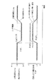
ここで、空燃比センサ24のセンサ誤差ΔGの算出方法及び空燃比センサ24の検出空燃比λs の補正方法について図7を用いて説明する。
空燃比F/B制御中に、目標空燃比λtgをλtg1 からλtg2 に変更すると、空燃比F/B補正係数FAFは、空燃比センサ24の検出空燃比λs を目標空燃比λtg1 に一致させる空燃比F/B補正係数FAF1 から目標空燃比λtg2 に一致させる空燃比F/B補正係数FAF2 に変化する。その際、センサ誤差ΔG(検出空燃比λs の誤差)が無ければ、目標空燃比の変化量(λtg1 −λtg2 )と空燃比F/B補正係数の変化量(FAF2 −FAF1 )とがほぼ同じになる。しかし、センサ誤差ΔGが有ると、目標空燃比の変化量(λtg1 −λtg2 )に対してセンサ誤差ΔGに応じた分だけ空燃比F/B補正係数の変化量(FAF2 −FAF1 )が異なってくる。
【0031】
そこで、本実施形態(1)では、目標空燃比の変化量(λtg1 −λtg2 )と空燃比F/B補正係数の変化量(FAF2 −FAF1 )との誤差をセンサ誤差ΔGとして求める。
ΔG=(λtg1 −λtg2 )−(FAF2 −FAF1 )
【0032】
また、目標空燃比λtgをλtg1 からλtg2 に変更した場合のセンサ誤差ΔGに応じて検出空燃比λs の変化量(λs2−λs1)と実空燃比λr の変化量(λr2−λr1)との関係が変化するので、センサ誤差ΔGに応じた補正係数Kを用いて、検出空燃比λs の変化量(λs2−λs1)と実空燃比λr の変化量(λr2−λr1)との関係を次式のように表すことができる。
(λr2−λr1)=K×(λs2−λs1) ……(A)
【0033】
ここで、目標空燃比λtg1 が理論空燃比(λ=1.0)の場合は、図2に示す空燃比センサ24の出力特性から、センサ誤差ΔG=0となるため、検出空燃比λs1=1.0、実空燃比λr1=1.0となる。この関係から、目標空燃比λtg1 が理論空燃比(λ=1.0)の場合は、上記(A)式を次式のように書き換えることができる。
(λr2−1.0)=K×(λs2−1.0) ……(B)
【0034】
更に、検出空燃比λs2を補正前の検出空燃比λs0とし、実空燃比λr2を補正後の検出空燃比λs とすると、上記(B)式を次式のにように書き換えることができる。
λs =K×(λs0−1.0)+1.0 ……(C)
本実施形態(1)では、上記(C)式を用いて空燃比センサ24の検出空燃比λs0を補正して最終的な検出空燃比λs を求める。
【0035】
以下、ECU27が実行する図3に示す燃料噴射量算出ルーチンと、図4乃至図6に示すセンサ誤差及び補正係数算出ルーチンの処理内容を説明する。
【0036】
[燃料噴射量算出]
図3に示す燃料噴射量算出ルーチンは、例えば燃料噴射タイミング毎に実行され、特許請求の範囲でいう空燃比制御手段としての役割を果たす。
本ルーチンが起動されると、まず、ステップ101で、燃料カット実行フラグXFCが「0」にリセットされているか否かを判定する。この燃料カット実行フラグXFCは、減速運転時であること等の燃料カット実行条件が成立しているときに「1」にセットされる。
【0037】
このステップ101で、燃料カット実行フラグXFCが「1」にセットされている判定されれば、ステップ102に進み、燃料噴射量TAUを「0」に設定して、燃料カットを実行する。
【0038】
一方、ステップ101で、燃料カット実行フラグXFCが「0」にリセットされていると判定された場合には、ステップ103に進み、基本燃料噴射量Tpのマップ(図示せず)を検索して、現在の運転状態(例えばエンジン回転速度NEと吸気管圧力PM)に応じた基本燃料噴射量Tpを算出する。
【0039】
この後、ステップ104に進み、空燃比F/B制御実行フラグXFBが「1」にセットされているか否かを判定する。この空燃比F/B制御実行フラグXFBは、空燃比F/B制御実行条件が成立しているときに「1」にセットされる。空燃比F/B制御実行条件は、例えば、エンジン冷却水温が所定温度以上であること、エンジン運転状態が高回転・高負荷領域ではないこと等であり、これらの条件を全て満たしたときに空燃比F/B制御実行条件が成立する。
【0040】
このステップ104で、空燃比F/B制御実行フラグXFBが「0」にリセットされていると判定されれば、ステップ109に進み、空燃比F/B補正係数FAFを「1.0」に設定した後、ステップ110に進む。この場合は、空燃比のF/B制御は行われない。
【0041】
一方、ステップ104で、空燃比F/B制御実行フラグXFBが「1」にセットされていると判定された場合には、ステップ105に進み、リッチ制御実行フラグXRICHが「1」にセットされているか否かを判定する。このリッチ制御実行フラグXRICHは、燃料カット終了後に所定期間だけ「1」にセットされる。
【0042】
このステップ105で、リッチ制御実行フラグXRICHが「0」にリセットされていると判定されれば、ステップ106に進み、目標空燃比λtgを通常時の目標空燃比λtg1 に設定する。この通常時の目標空燃比λtg1 は、理論空燃比又はその近傍の値(例えばλ=1.0)に設定されている。
【0043】
一方、ステップ105で、リッチ制御実行フラグXRICHが「1」にセットされている判定され場合には、ステップ107に進み、目標空燃比λtgをリッチ制御時の目標空燃比λtg2 に設定する。このリッチ制御時の目標空燃比λtg2 は、理論空燃比よりもリッチ方向にシフトした値(例えばλ=0.96)に設定される。
【0044】
この後、ステップ108に進み、空燃比センサ24で検出した排出ガスの検出空燃比λs を目標空燃比λtgに一致させるように空燃比F/B補正係数FAFを算出した後、ステップ110に進み、冷却水温、電気負荷等に応じた他の補正係数FALLを算出する。
【0045】
この後、ステップ111に進み、基本燃料噴射量Tp、空燃比F/B補正係数FAF及び他の補正係数FALLを用いて燃料噴射量TAUを次式により算出する。
TAU=Tp×FAF×FALL
【0046】
[センサ誤差及び補正係数算出]
図4乃至図6に示すセンサ誤差及び補正係数算出ルーチンは、例えば燃料噴射タイミング毎に実行され、特許請求の範囲でいうセンサ誤差学習手段としての役割を果たす。
【0047】
本ルーチンが起動されると、まず、ステップ201で、空燃比F/B制御を実行中であるか否かを判定する。その結果、空燃比F/B制御を実行中でないと判定された場合には、図5のステップ204に進み、通常時(目標空燃比λtg= 1.0)の空燃比F/B補正係数平均値FAF1av の演算時間をカウントするカウンタC1を所定値(例えば200)にセットした後、ステップ205に進み、通常時の空燃比F/B補正係数平均値FAF1av を「0」にリセットする。
【0048】
この後、ステップ206に進み、目標空燃比シフト時の空燃比F/B補正係数平均値FAF2av の演算時間をカウントするカウンタC2を初期値(例えば200)にリセットした後、ステップ207に進み、目標空燃比シフト時の空燃比F/B補正係数平均値FAF2av を「0」にリセットして本ルーチンを終了する。
【0049】
一方、図4のステップ201で、空燃比F/B制御を実行中であると判定された場合には、ステップ202に進み、目標空燃比λtgが理論空燃比付近(例えば0.98〜1.01の範囲内)であるか否かを判定する。
【0050】
目標空燃比λtgが通常時の目標空燃比λtg1 (例えば1.0)に設定されているときには、ステップ202で、「Yes」と判定されて、ステップ203に進み、目標空燃比シフト済みフラグXchg が「1」にセットされている否かを判定する。その結果、目標空燃比シフト済みフラグXchg が、まだ「1」にセットされていないと判定されれば、図5のステップ204に進む。
【0051】
その後、目標空燃比λtgが目標空燃比シフト時(例えばリッチ制御時)の目標空燃比λtg2 (例えば0.96)にシフトされたときに、ステップ202で、「No」と判定されて、ステップ208に進み、目標空燃比シフト時の空燃比F/B補正係数平均値FAF2av の演算時間をカウントするカウンタC2のカウント値を「1」だけデクリメントした後、ステップ209に進み、カウンタC2のカウント値が0以下になったか否かを判定する。
【0052】
その結果、カウンタC2が0以下になっていないと判定されれば、ステップ210に進み、目標空燃比シフト時の空燃比F/B補正係数平均値FAF2av (なまし値)を次式により算出する。
FAF2av(i)=1/32×FAF+31/32×FAF2av(i−1)
ここで、FAF2av(i)は今回の空燃比F/B補正係数平均値、FAF2av(i−1)は前回の空燃比F/B補正係数平均値、FAFは現在の空燃比F/B補正係数である。
【0053】
その後、ステップ209で、カウンタC2が0以下になったと判定されたときに、ステップ211に進み、目標空燃比シフト済みフラグXchg を「1」にセットする。
【0054】
その後、リッチ制御が終了して目標空燃比λtgが通常時の目標空燃比λtg1 (例えば1.0)に戻されたときに、図4のステップ202とステップ203で、共に「Yes」と判定されて、ステップ212に進み、通常時の空燃比F/B補正係数平均値FAF1av の演算時間をカウントするカウンタC1のカウント値を「1」だけデクリメントした後、ステップ213に進み、カウンタC1のカウント値が0以下になったか否かを判定する。
【0055】
その結果、カウンタC1が0以下になっていないと判定されれば、ステップ214に進み、通常時の空燃比F/B補正係数平均値FAF1av (なまし値)を次式により算出する。
FAF1av(i)=1/32×(FAF−1.0+λtg)+31/32×FAF1av(i−1)
ここで、FAF1av(i)は今回の空燃比F/B補正係数平均値、FAF1av(i−1)は前回の空燃比F/B補正係数平均値、FAFは現在の空燃比F/B補正係数である。
【0056】
その後、ステップ213で、カウンタC1が0以下になったと判定されたときに、図6のステップ215に進み、目標空燃比シフト済みフラグXchg を「0」にリセットする。
【0057】
この後、ステップ216に進み、目標空燃比の変化量(λtg1 −λtg2 )と空燃比F/B補正係数平均値の変化量(FAF2av −FAF1av )との差分をセンサ誤差ΔGとして算出し、これをセンサ誤差ΔGの学習値としてECU27のメモリに記憶する。
ΔG=(λtg1 −λtg2 )−(FAF2av −FAF1av )
【0058】
この後、ステップ217に進み、図8に示す補正係数Kのマップを検索して、センサ誤差ΔGに応じた補正係数Kを算出する。
ECU27は、この補正係数Kを用いて目標空燃比シフト時の空燃比センサ24の検出空燃比λs0を次式により補正して最終的な検出空燃比λs を求める。
λs =K×(λs0−1.0)+1.0
【0059】
以上説明した本実施形態(1)では、空燃比A/F制御の実行中に目標空燃比λtgを変更したときに、その変更前後の目標空燃比λtgと空燃比F/B補正係数FAFとに基づいてセンサ誤差ΔGを学習し、そのセンサ誤差ΔGに基づいて算出した補正係数Kを用いて空燃比センサ24の検出空燃比λs0を補正するので、センサ誤差ΔGが大きくなるリッチ制御時の空燃比領域であっても、空燃比センサ24の空燃比検出精度を向上させることができ、空燃比制御精度の向上、排気エミッションの低減を実現することができる。
【0060】
また、本実施形態(1)では、目標空燃比λtgを理論空燃比付近の値λtg1 (例えば1.0)と、理論空燃比よりもリッチ方向にシフトした値λtg2 (例えば0.96)との間で変更したときに、センサ誤差ΔGの学習を実行するようにしたので、センサ誤差の影響がほとんど含まれない空燃比F/B補正係数FAF1 と、センサ誤差の影響が含まれた空燃比F/B補正係数FAF2 とを用いてセンサ誤差ΔGを学習することができ、センサ誤差ΔGを精度良く学習することができる利点がある。
【0061】
尚、図4乃至図6のセンサ誤差及び補正係数算出ルーチンで行われるセンサ誤差ΔGの学習タイミングは、燃料カット終了後のリッチ制御時のみではなく、リッチ制御以外で目標空燃比をリッチ方向又はリーン方向に変更したときでも、センサ誤差ΔGの学習が行われるようになっている。この場合、目標空燃比λtgを所定量以上変更したときのみに、センサ誤差ΔGの学習を行うようにすると良い。このようにすれば、目標空燃比λtgの変更量がセンサ誤差ΔGの学習精度を十分に確保できる所定量以上になったときのみ、センサ誤差ΔGを学習することができ、センサ誤差の学習精度を確実に向上させることができる。
但し、本発明は、燃料カット終了後のリッチ制御時のみにセンサ誤差の学習を行うようにしても良いことは言うまでもない。
【0062】
《実施形態(2)》
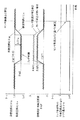
前記実施形態(1)では、リッチ制御時のセンサ誤差ΔGに基づいてリッチ制御時の空燃比センサ24の検出空燃比λs0を補正するようにしたが、図9に示す本発明の実施形態(2)では、リッチ制御時のセンサ誤差ΔGに基づいてリッチ制御時の目標空燃比シフト量Δλtg(=λtg2 −λtg1 )を補正してリッチ制御時の目標空燃比λtg2 を補正するようにしている。或は、リッチ制御時のセンサ誤差ΔGに基づいてリッチ制御時の空燃比F/B補正係数FAF2 を補正するようにしても良い。これらいずれの場合も、リッチ制御時のセンサ誤差ΔGを補償するようにリッチ制御時の目標空燃比λtg2 又は空燃比F/B補正係数FAF2 を補正することができ、実空燃比を本来の目標空燃比に精度良く制御することができる。
【0063】
尚、上記各実施形態(1)、(2)では、目標空燃比λtgをリッチ制御時の目標空燃比λtg2 に制御している状態から通常時の目標空燃比λtg1 に変更したとき、つまり目標空燃比λtgをリッチから理論空燃比に変更したときに、センサ誤差ΔGを学習するようにしたが、これとは反対に、目標空燃比λtgを通常時の目標空燃比λtg1 に制御している状態からリッチ制御時の目標空燃比λtg2 に変更したとき、つまり目標空燃比λtgを理論空燃比からリッチに変更したときに、センサ誤差ΔGを学習するようにしても良い。
【0064】
その他、本発明は、リーンバーンエンジンや筒内噴射エンジンに適用して、空燃比A/F制御中に目標空燃比を切り換える毎にセンサ誤差を学習するようにしても良い等、種々変更して実施できる。
【図面の簡単な説明】
【図1】本発明の実施形態(1)におけるエンジン制御システム全体の概略構成図
【図2】空燃比センサの出力特性図
【図3】燃料噴射量算出ルーチンの処理の流れを示すフローチャート
【図4】センサ誤差及び補正係数算出ルーチンの処理の流れを示すフローチャート(その1)
【図5】センサ誤差及び補正係数算出ルーチンの処理の流れを示すフローチャート(その2)
【図6】センサ誤差及び補正係数算出ルーチンの処理の流れを示すフローチャート(その3)
【図7】センサ誤差ΔGの算出方法を説明するためのタイムチャート
【図8】補正係数Kのマップを概念的に示す図
【図9】実施形態(2)を説明するためのタイムチャート
【符号の説明】
11…エンジン(内燃機関)、12…吸気管、15…スロットルバルブ、20…燃料噴射弁、21…点火プラグ、22…排気管、23…触媒、24…空燃比センサ、27…ECU(空燃比制御手段,センサ誤差学習手段)。[0001]
TECHNICAL FIELD OF THE INVENTION
The present invention relates to an air-fuel ratio control device for an internal combustion engine having a function of learning an output error of an air-fuel ratio sensor that detects an air-fuel ratio of exhaust gas of an internal combustion engine.
[0002]
[Prior art]
In recent years, in an internal combustion engine mounted on a vehicle, a target air-fuel ratio of exhaust gas is set near a stoichiometric air-fuel ratio which is a purification window of a catalyst such as a three-way catalyst, and an air-fuel ratio of exhaust gas detected by an air-fuel ratio sensor is set. By performing feedback control of the air-fuel ratio so as to match the target air-fuel ratio, the exhaust gas purification efficiency of the catalyst is increased.
[0003]
Further, in recent vehicles, fuel cut is performed to stop fuel injection at the time of deceleration operation or the like to improve fuel efficiency. Therefore, a large amount of oxygen in the unburned exhaust gas is adsorbed by the catalyst. For this reason, even if the air-fuel ratio of the exhaust gas is feedback-controlled near the stoichiometric air-fuel ratio, which is the normal target air-fuel ratio, after the fuel cut, even if the catalyst has the original purification capability due to the large amount of oxygen adsorbed on the catalyst during the fuel cut. Can not get.
[0004]
Therefore, recent vehicles perform rich control to temporarily shift the target air-fuel ratio in a richer direction than the stoichiometric air-fuel ratio after the fuel cut to control the exhaust gas air-fuel ratio to be richer than the stoichiometric air-fuel ratio. As a result, the oxygen adsorbed on the catalyst is reacted with HC in the exhaust gas to remove it, thereby restoring the original purification ability of the catalyst.
[0005]
In general, as shown in FIG. 2, the output characteristic of the air-fuel ratio sensor is close to the stoichiometric air-fuel ratio (excess air ratio λ = 1), the error (tolerance) with respect to the standard output characteristic is almost zero, and the air-fuel ratio detection is highly accurate. However, the detection error with respect to the standard output characteristics increases as the distance from the stoichiometric air-fuel ratio increases, and the detection accuracy decreases. For this reason, even if the air-fuel ratio of the exhaust gas is feedback-controlled to the target air-fuel ratio λtg that is richer than the stoichiometric air-fuel ratio during the rich control after the end of the fuel cut described above, the detection accuracy of the air-fuel ratio sensor in the rich air-fuel ratio region is increased. Therefore, the air-fuel ratio of the exhaust gas cannot be accurately controlled to the target air-fuel ratio λtg in the rich control. As a result, the actual air-fuel ratio λr of the exhaust gas shifts to the rich side from the target air-fuel ratio λtg at the time of the rich control, and the emission of rich components such as CO and HC increases, or the actual air-fuel ratio of the exhaust gas increases. λr may deviate from the target air-fuel ratio λtg during the rich control to the lean side, and the NOx emission may increase.
[0006]
Therefore, as a technique for compensating for an error in the output of the air-fuel ratio sensor, for example, as described in Patent Document 1 (Japanese Patent Application Laid-Open No. 9-203343), the air-fuel ratio until a predetermined time elapses from the start of fuel cut. The change characteristic (slope characteristic) of the sensor output is learned, and the change characteristic is compared with a predetermined reference change characteristic (slope characteristic) to generate correction data. Some are corrected.
[0007]
Further, as described in Patent Document 2 (Japanese Patent No. 2503381), the actual limit current of the air-fuel ratio sensor is detected in a specific operation state (for example, a steady operation state with low and medium load), and the actual limit current is detected. A deviation between the limit current (detected air-fuel ratio) and a target limit current (target air-fuel ratio) stored in advance corresponding to a specific operating state is calculated, and a correction coefficient is calculated based on the deviation to perform the correction. In some cases, the output of the air-fuel ratio sensor is corrected by a coefficient.
[0008]
[Patent Document 1]
JP-A-9-203343 (
[Patent Document 2]
Japanese Patent No. 2503381 (
[0009]
[Problems to be solved by the invention]
In the sensor output correction method of
[0010]
Further, in the sensor output correction method of
[0011]
The present invention has been made in view of these circumstances, and an object of the present invention is to provide an air-fuel ratio control device for an internal combustion engine that can accurately learn an output error of an air-fuel ratio sensor.
[0012]
[Means for Solving the Problems]
In order to achieve the above object, an air-fuel ratio control apparatus for an internal combustion engine according to
[0013]
If the target air-fuel ratio is changed during the air-fuel ratio feedback control, the air-fuel ratio feedback correction coefficient is changed from the air-fuel ratio feedback correction coefficient that matches the air-fuel ratio detected by the air-fuel ratio sensor to the target air-fuel ratio before the change. It changes to the air-fuel ratio feedback correction coefficient to be matched. At this time, if there is no sensor error, the change rate of the target air-fuel ratio and the change rate of the air-fuel ratio feedback correction coefficient become almost the same. However, if there is a sensor error (error of the detected air-fuel ratio), the change of the target air-fuel ratio The rate of change of the air-fuel ratio feedback correction coefficient differs from the rate by an amount corresponding to the sensor error. Therefore, when the target air-fuel ratio is changed, if the target air-fuel ratio before and after the change and the air-fuel ratio feedback correction coefficient are used, the change rate of the target air-fuel ratio and the change rate of the air-fuel ratio feedback correction coefficient are obtained. The sensor error can be learned with high accuracy from the difference in the change ratio.
[0014]
According to the present invention, for example, if the detected air-fuel ratio of the air-fuel ratio sensor is corrected based on the learned value of the sensor error, the actual air-fuel ratio can be detected with high accuracy. The air-fuel ratio can be accurately feedback-controlled to the target air-fuel ratio.
[0015]
Instead of correcting the detected air-fuel ratio of the air-fuel ratio sensor based on the learned value of the sensor error, the target air-fuel ratio or the air-fuel ratio feedback correction coefficient is corrected based on the learned value of the sensor error. Alternatively, the air-fuel ratio feedback control may be performed. With this configuration, the target air-fuel ratio or the air-fuel ratio feedback correction coefficient can be corrected so as to compensate for the error in the air-fuel ratio detected by the air-fuel ratio sensor, and the actual air-fuel ratio is accurately fed back to the original target air-fuel ratio. Can be controlled.
[0016]
Generally, as shown in FIG. 2, the air-fuel ratio sensor has a characteristic that the sensor error becomes almost zero near the stoichiometric air-fuel ratio even if the output characteristics vary, so that the target air-fuel ratio of the air-fuel ratio feedback control is When the air-fuel ratio is near the stoichiometric air-fuel ratio, the air-fuel ratio feedback correction coefficient hardly includes the influence of the sensor error.
[0017]
Therefore, the sensor error may be learned when the target air-fuel ratio is changed between the stoichiometric air-fuel ratio (or a value close to the stoichiometric air-fuel ratio) and other air-fuel ratios. With this configuration, the sensor error can be learned using the air-fuel ratio feedback correction coefficient that hardly includes the effect of the sensor error and the air-fuel ratio feedback correction coefficient that includes the effect of the sensor error. Can be learned with higher accuracy.
[0018]
Also, when the change amount of the target air-fuel ratio is small, the change amount of the air-fuel ratio feedback correction coefficient is also small. Therefore, the learning accuracy of the sensor error tends to decrease.
[0019]
Therefore, the sensor error may be learned when the target air-fuel ratio is changed by a predetermined amount or more. With this configuration, the sensor error can be learned only when the change amount of the target air-fuel ratio is equal to or more than a predetermined amount that can sufficiently secure the learning accuracy of the sensor error, and the learning accuracy of the sensor error is reliably improved. Can be done.
[0020]
Specifically, when the target air-fuel ratio is changed to a richer direction than the stoichiometric air-fuel ratio in order to remove oxygen adsorbed on the exhaust gas purifying catalyst after the fuel cut, as described in claim 4, The sensor error may be learned. After the end of the fuel cut, the target air-fuel ratio is temporarily changed relatively largely in the rich direction, so that the sensor error can be accurately learned.
[0021]
BEST MODE FOR CARRYING OUT THE INVENTION
<< Embodiment (1) >>
Hereinafter, an embodiment (1) of the present invention will be described with reference to FIGS. First, a schematic configuration of the entire engine control system will be described with reference to FIG. An
[0022]
Further, on the downstream side of the
[0023]
On the other hand, a
[0024]
The outputs of the various sensors described above are input to an engine control circuit (hereinafter referred to as “ECU”) 27. The
[0025]
In the program of the present embodiment described below, the excess air ratio λ, which is the ratio of the actual air-fuel ratio to the stoichiometric air-fuel ratio, is used as the information of the “air-fuel ratio”.
[0026]
The
[0027]
Further, while the fuel cut execution condition such as the deceleration operation is satisfied, the fuel cut for stopping the fuel injection is executed, and the target air-fuel ratio λtg is temporarily set during the air-fuel ratio F / B control after the end of the fuel cut. By performing rich control for shifting the detected air-fuel ratio λs of the air-
[0028]
In general, as shown in FIG. 2, the output characteristic of the air-
[0029]
Accordingly, the
[0030]
Here, a method of calculating the sensor error ΔG of the air-
When the target air-fuel ratio λtg is changed from λtg1 to λtg2 during the air-fuel ratio F / B control, the air-fuel ratio F / B correction coefficient FAF makes the air-fuel ratio λs detected by the air-
[0031]
Therefore, in the present embodiment (1), an error between the change amount (λtg1−λtg2) of the target air-fuel ratio and the change amount (FAF2-FAF1) of the air-fuel ratio F / B correction coefficient is obtained as a sensor error ΔG.
ΔG = (λtg1−λtg2) − (FAF2-FAF1)
[0032]
The relationship between the change amount (λs2−λs1) of the detected air-fuel ratio λs and the change amount (λr2-λr1) of the detected air-fuel ratio λs and the actual air-fuel ratio λr in accordance with the sensor error ΔG when the target air-fuel ratio λtg is changed from λtg1 to λtg2. Therefore, the relationship between the change amount (λs2−λs1) of the detected air-fuel ratio λs and the change amount (λr2−λr1) of the actual air-fuel ratio λr is calculated using the correction coefficient K corresponding to the sensor error ΔG as follows: Can be expressed as
(Λr2-λr1) = K × (λs2-λs1) (A)
[0033]
Here, when the target air-fuel ratio λtg1 is the stoichiometric air-fuel ratio (λ = 1.0), the sensor error ΔG = 0 from the output characteristics of the air-
(Λr2-1.0) = K × (λs2-1.0) (B)
[0034]
Further, if the detected air-fuel ratio λs2 is the detected air-fuel ratio λs0 before correction and the actual air-fuel ratio λr2 is the detected air-fuel ratio λs after correction, the above equation (B) can be rewritten as the following equation.
λs = K × (λs0−1.0) +1.0 (C)
In the embodiment (1), the detected air-fuel ratio λs0 of the air-
[0035]
Hereinafter, processing contents of the fuel injection amount calculation routine shown in FIG. 3 and the sensor error and correction coefficient calculation routine shown in FIGS. 4 to 6 which are executed by the
[0036]
[Calculation of fuel injection amount]
The fuel injection amount calculation routine shown in FIG. 3 is executed, for example, at each fuel injection timing and plays a role as an air-fuel ratio control means referred to in the claims.
When this routine is started, first, in
[0037]
If it is determined in
[0038]
On the other hand, if it is determined in
[0039]
Thereafter, the routine proceeds to step 104, where it is determined whether or not the air-fuel ratio F / B control execution flag XFB is set to "1". The air-fuel ratio F / B control execution flag XFB is set to “1” when the air-fuel ratio F / B control execution condition is satisfied. The conditions for executing the air-fuel ratio F / B control include, for example, that the engine coolant temperature is equal to or higher than a predetermined temperature and that the engine operating state is not in a high rotation / high load range. The condition for executing the fuel ratio F / B control is satisfied.
[0040]
If it is determined in
[0041]
On the other hand, if it is determined in
[0042]
If it is determined in
[0043]
On the other hand, if it is determined in
[0044]
Thereafter, the routine proceeds to step 108, where the air-fuel ratio F / B correction coefficient FAF is calculated so that the detected air-fuel ratio λs of the exhaust gas detected by the air-
[0045]
Thereafter, the routine proceeds to step 111, where the fuel injection amount TAU is calculated by the following equation using the basic fuel injection amount Tp, the air-fuel ratio F / B correction coefficient FAF, and another correction coefficient FALL.
TAU = Tp × FAF × FALL
[0046]
[Calculation of sensor error and correction coefficient]
The sensor error and correction coefficient calculation routine shown in FIGS. 4 to 6 is executed, for example, at each fuel injection timing, and plays a role as a sensor error learning means in claims.
[0047]
When this routine is started, first, in
[0048]
Thereafter, the process proceeds to step 206, where the counter C2 for counting the calculation time of the air-fuel ratio F / B correction coefficient average value FAF2av at the time of the target air-fuel ratio shift is reset to an initial value (for example, 200). The air-fuel ratio F / B correction coefficient average value FAF2av at the time of the air-fuel ratio shift is reset to “0”, and this routine ends.
[0049]
On the other hand, if it is determined in
[0050]
When the target air-fuel ratio λtg is set to the normal target air-fuel ratio λtg1 (for example, 1.0), “Yes” is determined in
[0051]
Thereafter, when the target air-fuel ratio λtg is shifted to the target air-fuel ratio λtg2 (for example, 0.96) at the time of the target air-fuel ratio shift (for example, during rich control), “No” is determined in
[0052]
As a result, if it is determined that the value of the counter C2 is not equal to or less than 0, the process proceeds to step 210, and the average value of the air-fuel ratio F / B correction coefficient FAF2av (average value) at the time of the target air-fuel ratio shift is calculated by the following equation. .
FAF2av (i) = 1/32 × FAF + 31/32 × FAF2av (i−1)
Here, FAF2av (i) is the current air-fuel ratio F / B correction coefficient average value, FAF2av (i-1) is the previous air-fuel ratio F / B correction coefficient average value, and FAF is the current air-fuel ratio F / B correction coefficient. It is.
[0053]
Thereafter, when it is determined in
[0054]
Thereafter, when the rich control ends and the target air-fuel ratio λtg is returned to the normal target air-fuel ratio λtg1 (for example, 1.0), both of
[0055]
As a result, if it is determined that the value of the counter C1 has not become equal to or less than 0, the routine proceeds to step 214, and the normal air-fuel ratio F / B correction coefficient average value FAF1av (average value) is calculated by the following equation.
FAF1av (i) = 1/32 × (FAF−1.0 + λtg) + 31/32 × FAF1av (i−1)
Here, FAF1av (i) is the current air-fuel ratio F / B correction coefficient average value, FAF1av (i-1) is the previous air-fuel ratio F / B correction coefficient average value, and FAF is the current air-fuel ratio F / B correction coefficient. It is.
[0056]
Thereafter, when it is determined in
[0057]
Thereafter, the process proceeds to step 216, where the difference between the target air-fuel ratio change amount (λtg1−λtg2) and the air-fuel ratio F / B correction coefficient average change amount (FAF2av−FAF1av) is calculated as a sensor error ΔG. The learned value of the sensor error ΔG is stored in the memory of the
ΔG = (λtg1−λtg2) − (FAF2av−FAF1av)
[0058]
Thereafter, the process proceeds to step 217, where a map of the correction coefficient K shown in FIG. 8 is searched, and the correction coefficient K corresponding to the sensor error ΔG is calculated.
Using the correction coefficient K, the
λs = K × (λs0−1.0) +1.0
[0059]
In the embodiment (1) described above, when the target air-fuel ratio λtg is changed during the execution of the air-fuel ratio A / F control, the target air-fuel ratio λtg and the air-fuel ratio F / B correction coefficient FAF before and after the change are changed. The sensor error ΔG is learned based on the sensor error ΔG, and the detected air-fuel ratio λs0 of the air-
[0060]
Also, in the present embodiment (1), the target air-fuel ratio λtg is set to a value λtg1 (eg, 1.0) near the stoichiometric air-fuel ratio and a value λtg2 (eg, 0.96) shifted in a richer direction than the stoichiometric air-fuel ratio. Since the learning of the sensor error ΔG is executed when it is changed between the air-fuel ratio F / B correction coefficient FAF1 and the air-fuel ratio F that includes the influence of the sensor error, the learning of the sensor error ΔG is executed. The sensor error ΔG can be learned by using the / B correction coefficient FAF2, and the sensor error ΔG can be learned with high accuracy.
[0061]
The learning timing of the sensor error ΔG performed in the sensor error and correction coefficient calculation routine of FIGS. 4 to 6 is not limited to the time of the rich control after the end of the fuel cut. Even when the direction is changed, learning of the sensor error ΔG is performed. In this case, the learning of the sensor error ΔG may be performed only when the target air-fuel ratio λtg is changed by a predetermined amount or more. With this configuration, the sensor error ΔG can be learned only when the change amount of the target air-fuel ratio λtg is equal to or more than a predetermined amount that can sufficiently secure the learning accuracy of the sensor error ΔG. It can surely be improved.
However, in the present invention, it goes without saying that the learning of the sensor error may be performed only during the rich control after the fuel cut.
[0062]
<< Embodiment (2) >>
In the embodiment (1), the detected air-fuel ratio λs0 of the air-
[0063]
In the above embodiments (1) and (2), when the target air-fuel ratio λtg is changed from the state in which the target air-fuel ratio λtg is controlled to the target air-fuel ratio λtg2 in the rich control to the target air-fuel ratio λtg1 in the normal state, that is, the target air-fuel ratio When the fuel ratio λtg is changed from rich to the stoichiometric air-fuel ratio, the sensor error ΔG is learned. On the contrary, from the state where the target air-fuel ratio λtg is controlled to the normal target air-fuel ratio λtg1. The sensor error ΔG may be learned when the target air-fuel ratio λtg2 during rich control is changed, that is, when the target air-fuel ratio λtg is changed from the stoichiometric air-fuel ratio to rich.
[0064]
In addition, the present invention may be applied to a lean burn engine or a direct injection engine, and various changes may be made such that a sensor error is learned every time the target air-fuel ratio is switched during the air-fuel ratio A / F control. Can be implemented.
[Brief description of the drawings]
FIG. 1 is a schematic configuration diagram of an entire engine control system according to an embodiment (1) of the present invention.
FIG. 2 is an output characteristic diagram of an air-fuel ratio sensor.
FIG. 3 is a flowchart showing the flow of processing of a fuel injection amount calculation routine;
FIG. 4 is a flowchart illustrating a processing flow of a sensor error and correction coefficient calculation routine (part 1);
FIG. 5 is a flowchart showing a processing flow of a sensor error and correction coefficient calculation routine (part 2);
FIG. 6 is a flowchart illustrating a processing flow of a sensor error and correction coefficient calculation routine (part 3);
FIG. 7 is a time chart for explaining a method of calculating a sensor error ΔG.
FIG. 8 is a diagram conceptually showing a map of a correction coefficient K;
FIG. 9 is a time chart for explaining the embodiment (2).
[Explanation of symbols]
DESCRIPTION OF
Claims (6)
前記空燃比制御手段による空燃比フィードバック制御の実行中に前記目標空燃比を変更したときに、その変更前後の目標空燃比と空燃比フィードバック補正係数とに基づいて前記空燃比センサの出力の誤差(以下「センサ誤差」という)を学習するセンサ誤差学習手段を備えていることを特徴とする内燃機関の空燃比制御装置。An internal combustion engine comprising: an air-fuel ratio sensor that detects an air-fuel ratio of exhaust gas of an internal combustion engine; and an air-fuel ratio control unit that performs an air-fuel ratio feedback control so that the air-fuel ratio detected by the air-fuel ratio sensor matches a target air-fuel ratio. In the air-fuel ratio control device of
When the target air-fuel ratio is changed during execution of the air-fuel ratio feedback control by the air-fuel ratio control means, an error in the output of the air-fuel ratio sensor based on the target air-fuel ratio before and after the change and the air-fuel ratio feedback correction coefficient ( An air-fuel ratio control device for an internal combustion engine, comprising: a sensor error learning unit for learning a “sensor error”.
Priority Applications (2)
| Application Number | Priority Date | Filing Date | Title |
|---|---|---|---|
| JP2002269342A JP2004108183A (en) | 2002-09-17 | 2002-09-17 | Air-fuel ratio control device for internal combustion engine |
| US10/638,486 US6837232B2 (en) | 2002-09-17 | 2003-08-12 | Air-fuel ratio control apparatus for internal combustion engine |
Applications Claiming Priority (1)
| Application Number | Priority Date | Filing Date | Title |
|---|---|---|---|
| JP2002269342A JP2004108183A (en) | 2002-09-17 | 2002-09-17 | Air-fuel ratio control device for internal combustion engine |
Publications (1)
| Publication Number | Publication Date |
|---|---|
| JP2004108183A true JP2004108183A (en) | 2004-04-08 |
Family
ID=31986817
Family Applications (1)
| Application Number | Title | Priority Date | Filing Date |
|---|---|---|---|
| JP2002269342A Pending JP2004108183A (en) | 2002-09-17 | 2002-09-17 | Air-fuel ratio control device for internal combustion engine |
Country Status (2)
| Country | Link |
|---|---|
| US (1) | US6837232B2 (en) |
| JP (1) | JP2004108183A (en) |
Families Citing this family (9)
| Publication number | Priority date | Publication date | Assignee | Title |
|---|---|---|---|---|
| JP4233490B2 (en) * | 2004-05-25 | 2009-03-04 | 三菱電機株式会社 | Control device for internal combustion engine |
| US20070047384A1 (en) * | 2005-09-01 | 2007-03-01 | Mclaughlin Jon K | Control system for and method of combining materials |
| DE102005059794B3 (en) * | 2005-12-14 | 2007-03-29 | Siemens Ag | Exhaust gas probe calibrating method for use in internal combustion engine, involves detecting plateau phase of measuring signals of probe, after transfer of parameter of fat air-fuel ratio to parameter of lean air-fuel ratio |
| DE102006020349A1 (en) * | 2006-04-28 | 2007-10-31 | Mahle International Gmbh | Piston engine and associated operating method |
| JP2010174872A (en) * | 2009-02-02 | 2010-08-12 | Denso Corp | Malfunction diagnosis device for internal combustion engine secondary air supply system |
| US10202909B2 (en) * | 2009-02-20 | 2019-02-12 | Toyota Jidosha Kabushiki Kaisha | Spark ignition type internal combustion engine |
| US20150361913A1 (en) * | 2014-06-14 | 2015-12-17 | GM Global Technology Operations LLC | Method and apparatus for controlling an internal combustion engine with a lambda sensor |
| WO2016088191A1 (en) * | 2014-12-02 | 2016-06-09 | 日産自動車株式会社 | Controlling device for internal combustion engines |
| JP7188366B2 (en) * | 2019-11-27 | 2022-12-13 | トヨタ自動車株式会社 | engine device |
Family Cites Families (5)
| Publication number | Priority date | Publication date | Assignee | Title |
|---|---|---|---|---|
| JPH065047B2 (en) * | 1983-06-07 | 1994-01-19 | 日本電装株式会社 | Air-fuel ratio controller |
| JP2978960B2 (en) * | 1992-07-31 | 1999-11-15 | 本田技研工業株式会社 | Oxygen sensor deterioration detection device for internal combustion engine |
| US5964208A (en) * | 1995-03-31 | 1999-10-12 | Denso Corporation | Abnormality diagnosing system for air/fuel ratio feedback control system |
| US5778866A (en) * | 1996-01-25 | 1998-07-14 | Unisia Jecs Corporation | Air-fuel ratio detecting system of internal combustion engine |
| JP3813044B2 (en) * | 2000-01-05 | 2006-08-23 | 本田技研工業株式会社 | Air-fuel ratio control device for internal combustion engine |
-
2002
- 2002-09-17 JP JP2002269342A patent/JP2004108183A/en active Pending
-
2003
- 2003-08-12 US US10/638,486 patent/US6837232B2/en not_active Expired - Fee Related
Also Published As
| Publication number | Publication date |
|---|---|
| US20040050378A1 (en) | 2004-03-18 |
| US6837232B2 (en) | 2005-01-04 |
Similar Documents
| Publication | Publication Date | Title |
|---|---|---|
| JP2592342B2 (en) | Control device for internal combustion engine | |
| JP3902399B2 (en) | Air-fuel ratio control device for internal combustion engine | |
| JP2009115012A (en) | Air-fuel ratio control device of internal combustion engine | |
| JPH07305644A (en) | Air-fuel ratio controller of internal combustion engine | |
| JPH10318053A (en) | Air-fuel ratio control device for internal combustion engine | |
| JP2004108183A (en) | Air-fuel ratio control device for internal combustion engine | |
| JP4475207B2 (en) | Control device for internal combustion engine | |
| JPH0914022A (en) | Air-fuel ratio control device for internal combustion engine | |
| JP2007211609A (en) | Device for controlling air-fuel ratio per cylinder of internal combustion engine | |
| US7171949B2 (en) | Ignition timing controller for internal combustion engine | |
| JPH10159625A (en) | Air-fuel ratio control device for internal combustion engine | |
| JP3788497B2 (en) | Air-fuel ratio control device for internal combustion engine | |
| JP3412216B2 (en) | Exhaust gas purification device for internal combustion engine | |
| JP4349438B2 (en) | Air-fuel ratio control device for internal combustion engine | |
| JP3939026B2 (en) | Three-way catalyst oxygen storage control device | |
| JP2000310140A (en) | Air-fuel ratio control device for internal combustion engine | |
| JP2002349316A (en) | Exhaust emission purifying system for internal combustion engine | |
| JP3966177B2 (en) | Air-fuel ratio control device for internal combustion engine | |
| JP4258733B2 (en) | Air-fuel ratio control device for internal combustion engine | |
| JP4072412B2 (en) | Air-fuel ratio control device for internal combustion engine | |
| JP3187534B2 (en) | Air-fuel ratio correction method for internal combustion engine | |
| JP4604361B2 (en) | Control device for internal combustion engine | |
| JPH06200809A (en) | Air-fuel ratio control device of internal combustion engine | |
| JP2000097081A (en) | Air-fuel ratio control device of internal-combustion engine | |
| JP2011144791A (en) | Control device for cylinder injection type internal combustion engine |
Legal Events
| Date | Code | Title | Description |
|---|---|---|---|
| A621 | Written request for application examination |
Free format text: JAPANESE INTERMEDIATE CODE: A621 Effective date: 20041208 |
|
| A131 | Notification of reasons for refusal |
Free format text: JAPANESE INTERMEDIATE CODE: A131 Effective date: 20070727 |
|
| A977 | Report on retrieval |
Free format text: JAPANESE INTERMEDIATE CODE: A971007 Effective date: 20070801 |
|
| A521 | Request for written amendment filed |
Free format text: JAPANESE INTERMEDIATE CODE: A523 Effective date: 20070830 |
|
| A02 | Decision of refusal |
Free format text: JAPANESE INTERMEDIATE CODE: A02 Effective date: 20071015 |