JP2004106863A - Packaging bag for use in microwave oven - Google Patents
Packaging bag for use in microwave oven Download PDFInfo
- Publication number
- JP2004106863A JP2004106863A JP2002269529A JP2002269529A JP2004106863A JP 2004106863 A JP2004106863 A JP 2004106863A JP 2002269529 A JP2002269529 A JP 2002269529A JP 2002269529 A JP2002269529 A JP 2002269529A JP 2004106863 A JP2004106863 A JP 2004106863A
- Authority
- JP
- Japan
- Prior art keywords
- packaging bag
- layer
- microwave oven
- sealant
- resin
- Prior art date
- Legal status (The legal status is an assumption and is not a legal conclusion. Google has not performed a legal analysis and makes no representation as to the accuracy of the status listed.)
- Pending
Links
Images


Abstract
Description
【0001】
【発明の属する技術分野】
本発明は、輸送や保管をするときに加わる圧力や衝撃によって剥離することなく、また、電子レンジで加熱するときに内容物を包装したまま破裂を起こさず、自動的に内圧を低下させることができる電子レンジ用包装袋に関するものである。
さらに詳しくは、内容物として、固形食品に加えて、例えば、カレー、スープ等の流動性食品、飲料水等の各種の飲食品を密封包装し、袋を横置に載置したまま内容物がこぼれることなく、安全に加熱することができる電子レンジ用包装袋に関するものである。
【0002】
【従来技術】
近年、電子レンジの普及発展に伴い、また、調理の簡便化の要請から、調理済み加工食品を、プラスチック製の包装袋等に包装し、密封して、保存性を持たせた形態で流通されている。
こうした食品を電子レンジで加熱する場合において、包装袋が、密封したままであると、加熱により内容物から発生する水蒸気により袋内の内圧が上昇し、ついには破裂し、内容物が電子レンジ庫内に飛散してしまうことが知られている。このような包装袋の破裂を防止するために、従来の包装容器としては、例えば、電子レンジで加熱する前に、包装袋の一部をはさみで切り、通気口を形成しておく包装容器がある(例えば、特許文献1参照。)。
また、消費者が、加熱する前に、前記の通気口を形成する作業を忘れてしまい、加熱して袋を破裂させる事態を回避するため、自動的に水蒸気を通気することができる種々の包装容器が提案されている。
電子レンジで加熱した際の容器内圧の上昇により、ガス抜き用の貫通細孔が、プラスチック容器のシール面上に塗布された剥離剤に沿って生じる包装容器がある(例えば、特許文献2参照。)。
また、同様の貫通細孔が、耐熱性のある熱可塑性樹脂層とシーラントフィルムとの中間に設けられた剥離剤層に沿ってシール面上に生じる包装容器もある(例えば、特許文献3参照。)。
【0003】
【特許文献1】
特開平10−72070号公報(第2−3頁、第3図)
【特許文献2】
特開平9−40030号公報(第4頁、第6図)
【特許文献3】
特開平9−272180号公報(第3−4頁、第4図)
【0004】
【発明が解決しようとする課題】
しかしながら、電子レンジで加熱する前に、包装袋の一部をはさみで切り、通気口を形成しておく包装容器は、手間がかかって面倒であり、また、消費者が加熱する前に、前記の通気口を形成する作業を忘れてしまい、加熱して袋を破裂させる恐れがあり、非常に危険である。
また、シール面上に剥離剤を塗布した包装容器の場合において、上記の剥離剤は、もともと剥離しやすくするために形成されているものであるため、通常の輸送時や保管時に加わる圧力や衝撃によってシール面から剥離するおそれがあった。
また、上記の剥離剤の塗布面がシール部分からはみ出すように形成されたものは、剥離剤が内容物と接触するため、好ましくなかった。
そのため、従来は、輸送時の衝撃等に耐えるように、剥離剤層のパターン形状を工夫したり、剥離剤層がシール部分からはみ出さないように精度よく形成しなければならないといった工程上の複雑な問題があった。
【0005】
さらに、本出願人は、本件出願に先立ち、耐熱性基材層とシーラント層の間に、室温以下の温度環境では所定の強度を有するが、高温の温度環境では軟化して強度が低下する樹脂層を設けた包装材料を用い、電子レンジ用包装袋の作製を試みた。
この電子レンジ用包装袋は、シール部の一部に上記の樹脂層が設けられているので、電子レンジで加熱されて起こる内圧の上昇によって開封し、包装袋内の圧力を自動的に逃がすことが可能であった。
【0006】
しかしながら、この電子レンジ用包装袋においては、内容物として、固形状の食品に対応できる包装袋であるが、カレー等の流動性食品、飲料水等の飲食品について、袋を開封する前に内容物がこぼれてしまうという恐れがあるため、流動性食品等の液体の入った飲食品の包装袋として対応できなかった。
【0007】
【課題を解決するための手段】
そこで本発明者らは、上記の課題を解決するために、鋭意研究の結果、本発明は、電子レンジにより加熱するための袋であって、耐熱性基材層とシーラント層の間に、室温以下の温度環境では所定の強度を有するが、高温の温度環境では前記所定の強度が低下する樹脂層を少なくとも一領域設けた積層フィルムを用いる包装袋であって、かつ、シーラント面を上面とした下部材と、シーラント面同士を向かい合わせて側部と先端辺部とをシールしたウィング部を形成し、シーラント面を下面とした上部材とを重ね合わせ、その周縁部をシールして主シール部として密封した包装袋であって、前記のウィング部を構成する上部材の1枚又は2枚が、前記の樹脂層を、シールしたウィング部の先端辺部の少なくとも一領域に、内側から外側に向かって横断するように形成してなることを特徴とする電子レンジ用包装袋を製造したところ、樹脂層のパターン形成の精度をシビアにする必要がなく、容易にパターン形成することができ、また、常温以下、すなわち食品等の包装工程時や包装後の冷凍時の環境温度領域においてシール強度に優れ、内容物がこぼれることもなく、また、電子レンジで加熱するときに内容物を包装したまま破裂を起こさず、自動的に内圧を低下させることができ、また、内容物として、固形食品に加えて流動性食品等の各種の飲食品を密封包装し、袋を横置に載置したまま内容物がこぼれることなく、安全に加熱することができる電子レンジ用包装袋を製造し得ることを見いだすに至った。
上記において、本発明によれば、前記の樹脂層を設けたウィング部の先端辺部の領域におけるシール強度が、80℃以上の高温の温度領域では10N/15mm以下となることを特徴とする電子レンジ用包装袋を提供することができる。
また、上記の包装袋の端部からウィング部までとウィング部から他端部までの長さの比が2/3以下であることを特徴とする電子レンジ用包装袋を提供することができる。
【0008】
【発明の実施の形態】
以下、本発明を具体的に説明する。
図1は、本発明の電子レンジ用包装袋に用いられる包装材料10の一例を示す断面図である。
図2は、本発明の電子レンジ用包装袋のシールしたウィング部の先端辺部の一例を示す拡大断面図である。
図3および図4は、本発明の電子レンジ用包装袋の一例を示す斜視図である。図5は、本発明の電子レンジ用包装袋の構造を示す説明図、及び、そのX1−X1部における断面図であり、図6は、ウィング部の先端辺部に設けられる樹脂層形成領域の形状の一例を示す平面図である。
図7は、図4のX2−X2部の断面図である。
図8および図9は、本発明の電子レンジ用包装袋に内容物を充填した包装体の断面図である。
図10および図11は、図8および図9の包装体のウィング部のシール部の(a)加熱前の状態と(b)加熱によって蒸気を放散する状態を示す拡大断面図である。
【0009】
まず、本発明にかかる電子レンジ用包装袋を形成する各部材について説明する。
図1は、本発明の電子レンジ対応包装袋に用いられる包装材料10の一例を示す断面図である。
図1(a)に示すように、包装材料10は、耐熱性基材層12、印刷層13、樹脂層14、接着層15、シーラント層16の順に積層されている。
なお、印刷層13と接着層15は、後述するように、必須の層ではなく、適宜必要に応じて設けられる層である。
従って、本発明で用いられる包装材料は、少なくとも耐熱性樹脂層12とシーラント層16の間に樹脂層14を備えた積層体である。
【0010】
更に、図1(b)に示すように、包装材料10は、耐熱性基材層12、印刷層13、中間層17、樹脂層14、接着層15、シーラント層16の順に積層されている。
なお、印刷層13、接着層15および中間層17は、後述するように、必須の層ではなく、適宜必要に応じて設けられる層である。
【0011】
耐熱性基材層12は、包装材料10の必須の層であり、この包装材料を用いて包装袋が作製された際には外側に配置されるように設けられる。
耐熱性基材層12としては、一般に電子レンジで加熱又は加熱調理される冷凍食品やチルド食品用の包装材料として使用されているものであれば特に限定されない。
例えば、延伸ポリエチレンテレフタレートフィルム、シリカ蒸着ポリエチレンテレフタレートフィルム、アルミナ蒸着ポリエチレンテレフタレートフィルム、延伸ナイロンフィルム、シリカ蒸着延伸ナイロンフィルム、アルミナ蒸着延伸ナイロンフィルム、延伸ポリプロピレンフィルム、ポリビニルアルコールコート延伸ポリプロピレンフィルム、ナイロン6/メタキシレンジアミンナイロン6共押共延伸フィルム、ポリプロピレン/エチレン−ビニルアルコール共重合体共押共延伸フィルム等のうち、何れかのフィルムを使用することができる。
これらの耐熱性樹脂層12は、融点が通常150℃以上であり、厚さは10〜50μmである。
【0012】
印刷層13は、従来公知の印刷方法等によって、内容表示または美感付与等の目的で設けられるものであり、必須の層ではなく、適宜必要に応じて設けられる。
通常、この印刷層13は、図1に示すように、耐熱性基材層12の上面側、すなわち包装袋が作製された際に耐熱性基材層12の内側(内容物側)になるように形成されてもよく、耐熱性基材層12の下面側、すなわち包装袋が作製された際に耐熱性基材層12の外側(内容物の反対側)になるように形成されてもよい。
【0013】
樹脂層14は、必須の層として、耐熱性樹脂層12とシーラント層16の間に設けられる。
この樹脂層14は、室温以下の温度環境では所定の強度を有するが、高温の温度環境ではその強度が低下する性質を有するものである。
【0014】
所定の強度を保持する室温以下の温度とは、通常、包装材料10を用いて食品等の内容物を包装する工程時の環境温度や、内容物を密封包装した後の包装袋や容器の冷凍工程時の環境温度や、冷凍食品を輸送、保管する際の環境温度である。
従って、樹脂層14は、こうした温度環境では、所定の強度が保持されることとなる。
一方、上記の所定の強度が低下する高温の温度環境とは、食品等の内容物を密封包装した包装袋や容器を、電子レンジで加熱又は加熱調理する際に加わる温度であり、こうした高い温度で樹脂層14の強度が低下することとなる。
【0015】
本発明では、このような性質を有する樹脂層14を、包装材料10のシールしたウィング部の先端辺部の少なくとも一領域に、包装袋の内側から外側に向かって横断するように設ける。
こうした位置に設けられた樹脂層14は、電子レンジで加熱されて高温になることによってその強度が低下するものである。
【0016】
図2は、本発明の電子レンジ用包装袋1のシールしたウィング部の先端辺部の一例を示す拡大断面図である。
図2の包装袋1のシール部分22の拡大断面図に示すように、形成された樹脂層14は、電子レンジで加熱等されて包装袋1内の空気の膨張や内容物に含まれる水蒸気によって内圧が上昇したとき、シール部22近傍のシーラント層16の任意の個所23を起点として、強度が低下した樹脂層14が破壊される(符号24は、破壊する仮想線を示す。)。
その結果、シール部22のシーラント層16と耐熱性基材層12との間に、包装袋1の内側から外側に向かって樹脂層14の破壊による比較的小さい大きさの空気抜けが生じるので、包装袋1内の蒸気等が逃げ、その内圧を低下させることができる。
本発明では、破壊が部分的に起こるので、比較的小さい大きさの空気抜けが生じ、包装袋1の内圧が一気に低下することがなく、内容物の飛散が起こらない。
【0017】
このような性質を有する樹脂層14として、60〜90℃の融点を有する材料、例えば、エチレン−酢酸ビニル系共重合体樹脂、ポリアミド系樹脂、ポリアミド−硝化綿系樹脂、ポリアミド−硝化綿−ポリエチレンワックス系樹脂、ウレタン−ポリアミド−硝化綿系樹脂またはポリエチレンワックス−硝化綿系樹脂を含有する樹脂を挙げることができる。
融点が60〜90℃の樹脂層を用いることによって、電子レンジで加熱した際に、樹脂層14とシーラント層16の一部の部分的な破壊を起こりやすくさせるという利点を有する。
【0018】
樹脂層14の形成は、従来公知の樹脂コーティング法を用いることができ、その厚さは、1〜5μmであることが好ましい。
樹脂層14の厚さが1μm未満では、電子レンジで加熱した際に、樹脂層14とシーラント層16の破壊が起きにくいため好ましくない。
また、樹脂層14の厚さが5μmを越えると、樹脂層14のパターンによっては、得られたフィルム状の包装材料をロール状に巻いたときに、一部に盛り上がりが生じ、その部分の包装材料が伸びてしまうため好ましくない。
【0019】
包装材料10は、後述するシーラント層16を向かい合うように重ね合わせてシールした時に、樹脂層14を設けた領域のシール強度が、室温以下の温度領域では15(N/15mm)以上であり、80℃以上の高温の温度領域では10(N/15mm)以下であることが好ましく、1(N/15mm)〜6(N/15mm)の範囲にあることがより好ましい。
樹脂層14を設けた領域のシール強度が、室温以下の温度領域では15(N/15mm)以上であるので、室温時又は冷凍時の取扱、輸送、保管等によってはシール部が剥がれて開くことがない。
また、80℃以上の高温の温度領域では10(N/15mm)以下であるので、電子レンジで加熱した際に、樹脂層14とシーラント層16の一部が部分的に破壊する程度の強度まで低下する。
このような特性を有する包装材料によって作製された包装袋は、その範囲でシール強度を調整できるので、電子レンジで加熱されて内圧がある程度まで上昇したときに初めて部分的に破壊させるように調整するという利点を有する。
【0020】
シーラント層16は、必須の層として、樹脂層14上に設けられ、包装袋が作製される際には内容物に接触する最内層となる。
シーラント層16としては、低密度ポリエチレンフィルム、超低密度ポリエチレンフィルム、直鎖状低密度ポリエチレンフィルム、中密度ポリエチレンフィルム、高密度ポリエチレンフィルム、無延伸ポリプロピレンフィルム、エチレン−酢酸ビニル共重合体フィルム、エチレン−アクリル酸共重合体フィルム、エチレン−メタクリル酸共重合体フィルム、エチレン−メチルアクリレート共重合体フィルム、エチレン−エチルアクリレート共重合体フィルム、エチレン−メチルメタクリレート共重合体フィルム、アイオノマーフィルムのうち、何れか一種以上のフィルムが使用され、単層シーラント層または多層シーラント層とすることができる。
シーラント層は、これらの樹脂を押出しラミネート法で形成してもよく、予め、Tダイ法またはインフレーション法等により製膜したフィルムとして形成してもよい。
これらのシーラント層16の厚さは、通常20〜100μmが好ましく、30〜60μmがより好ましい。
本発明においては、包装袋が作製される際に、シーラント層16どうしが包装袋の被シール部でシール面を形成するため、従来の包装袋のようにシール強度の弱い剥離剤層によって一部のシール面が形成されることがないので、冷凍時、輸送時、保管時等において貼り合わされたシール面が破れて内容物の露出が起こることがない。
【0021】
シーラント層16は、高温の温度領域で樹脂層14の強度が低下することにより、密封された包装袋内で上昇した内圧をシーラント層16自身の強度によって維持しなければならなくなる。
そのため、図2に示すように、包装袋の内側のシール部22境界面付近のシーラント層16が、そのすぐ隣に設けられた樹脂層14の強度の低下によって、亀裂が生じやすくなり、遂には、内圧に耐えきれずに任意の個所23を起点として樹脂層14と共に破壊し、空気抜けが生ずることとなる。
【0022】
また、シーラント層16は、包装袋を構成する部材毎に異なる仕様から形成されてもよく、また、同一の仕様から形成されるものでもよい。
例えば、図2に示すように、前記の樹脂層を耐熱性基材層とシーラント層の間に形成する一方の上部材のシーラント16aの厚みを、他の上部材および下部材のシーラントより薄くすることが好ましい。
また、一方の上部材のシーラント16aの材質のみを例えば、低密度ポリエチレン、コモノマ−の炭素数4の直鎖状低密度ポリエチレン(以下、「C4LLDPE」という。)等の引裂強度に優れる性質を有するシーラントを使用することが好ましく、中でも、C4LLDPEが、シール性にも優れるため、より好ましいものである。
上記において、包装袋の内側のシール部22境界面付近のシーラント層16が、電子レンジで加熱する際、そのすぐ隣に設けられた樹脂層14の強度の低下によって、亀裂をより生じやすくなり、スムーズに開封することができ、好ましい。
【0023】
なお、中間層17として、例えば、酸素バリア層および衝撃吸収樹脂層の何れか一方または両方を設けることもできる。また、これらの層を数層設けることもできる。
例えば、酸素バリア層としては、塩化ビニリデンフィルム、エチレン−ビニルアルコール共重合体フィルム、無機物蒸着フィルムを用いることもできる。
衝撃吸収樹脂層としては、ナイロンフィルムが好適に用いられる。
ナイロンフィルムは、1軸延伸、2軸延伸または無延伸の何れのものであっても好適に用いることができる。
衝撃吸収樹脂層の厚さは特に限定されないが、通常5〜40μm、好ましくは10〜30μmの範囲である。
但し、こうした中間層を設ける場合であっても、樹脂層14は、最内層であるシーラント層16上、または接着層15を介してシーラント層16上に設けることが、空気抜けを容易に生じさせる観点から好ましい。
【0024】
包装材料の各層を形成する樹脂には、本発明の目的の達成を阻害しない範囲で、滑剤、酸化防止剤、帯電防止剤、着色剤のような公知の添加剤を随時添加することができる。
その添加量としては、極微量から数十%まで、その目的に応じて、任意に添加することができる。
【0025】
次に、上記の本発明において、上記のような材料を使用して積層体を製造する方法について説明すると、かかる方法としては、耐熱性基材層12、中間層17、樹脂層14、接着層15およびシーラント層16の層間は、例えば、ラミネート用接着剤によるラミネート用接着剤を介して積層するドライラミネーション法、あるいは、溶融押出し接着性樹脂による溶融押出し樹脂層を介して積層する押出しラミネーション法等で行うことができる。
【0026】
上記において、ラミネート用接着剤としては、例えば、1液、あるいは2液型の硬化ないし非硬化タイプのビニル系、(メタ)アクリル系、ポリアミド系、ポリエステル系、ポリエーテル系、ポリウレタン系、エポキシ系、ゴム系、その他等の溶剤型、水性型、あるいは、エマルジョン型等のラミネート用接着剤を使用することができる。
上記のラミネート用接着剤のコーティング方法としては、例えば、ダイレクトグラビアロールコート法、グラビアロールコート法、キスコート法、リバースロールコート法、フォンテン法、トランスファーロールコート法、その他の方法で塗布することができる。
その塗布量としては、0.1〜10g/m2(乾燥状態)位が好ましく、1〜5g/m2(乾燥状態)位がより好ましい。
【0027】
上記において、溶融押出性樹脂層としては、熱可塑性樹脂層からなる樹脂層が使用され、各層間を接着するために使用することができる。
具体的には、接着性の溶融押出性樹脂層の材料としては、低密度ポリエチレン樹脂、中密度ポリエチレン樹脂、高密度ポリエチレン樹脂、直鎖状低密度ポリエチレン樹脂、メタロセン触媒を利用して重合したエチレン・αオレフィンとの共重合体樹脂、エチレン・ポリプロピレン共重合体樹脂、エチレン・酢酸ビニル共重合体樹脂、エチレン・アクリル酸共重合体樹脂、エチレン・アクリル酸エチル共重合体樹脂、エチレン・メタクリル酸共重合体樹脂、エチレン・メタクリル酸メチル共重合体樹脂、エチレン・マレイン酸共重合体樹脂、アイオノマー樹脂、ポリオレフィン樹脂に不飽和カルボン酸、不飽和カルボン酸、不飽和カルボン酸無水物、エステル単量体をグラフト重合、または、共重合した樹脂、無水マレイン酸をポリオレフィン樹脂にグラフト変性した樹脂等を使用することができる。これらの材料は、一種ないしそれ以上を組み合わせて使用することができる。
その樹脂層の厚みとしては、10〜30μm位が好ましい。
【0028】
なお、上記の積層を行う場合、必要ならば、例えば、コロナ処理、オゾン処理、フレ−ム処理、その他等の前処理を施し、積層することができる。
上記の表面前処理は、各種の樹脂のフィルムないしシートと各層を積層する際、密着性等を改良するための方法として実施するものであるが、上記の密着性を改良する方法として、例えば、各種の樹脂のフィルムないしシートの表面に、予め、プライマーコート剤層、アンダーコート剤層、アンカーコート剤層等を任意に形成して、表面処理層とすることもできる。
【0029】
上記の前処理のコート剤層としては、例えば、ポリエステル系樹脂、ポリアミド系樹脂、ポリウレタン系樹脂、エポキシ樹脂、フェノール系樹脂、(メタ)アクリル系樹脂、ポリ酢酸ビニル系樹脂、ポリエチレンあるいはポリプロピレン等のポリオレフィン系樹脂あるいはその共重合体ないし変性樹脂、セルロース系樹脂、その他等をビヒクルの主成分とする樹脂組成物を使用することができる。
【0030】
以上に説明した包装材料10を、シーラント層16が向かい合うように重ね合わせ、所望の被シール部をヒートシールすることによって、本発明にかかる種々の形態の電子レンジ用包装袋を製造することができる。
【0031】
次に、本発明の電子レンジ用包装袋の種々の形態について説明すると、図3は、本発明の電子レンジ用包装袋の一例を示す斜視図である。
図3に示すように、本発明の電子レンジ用包装袋は、袋の片面にウィング部を設けた袋である。
而して、本発明の電子レンジ用包装袋は、前記のウィング部を設けた上面として電子レンジで加熱できるものである。
【0032】
図3に示すように、本発明の電子レンジ用包装袋における前記ウィング部の位置は、包装袋の端辺から偏在させ、上記の包装袋の端部からウィング部aまでとウィング部から他端部bまでの長さの比が2/3以下であることが望ましい。
前記の距離が2/3を超えると、電子レンジによる加熱の際、好ましい自動開口ができない。
【0033】
図3に示すように、蒸気口の幅の狭い方が、開封時の音が軽減される傾向があるために、前記のウィング部にガイドシール部5Gを設けてもよい。
【0034】
図4は、本発明の別態様の電子レンジ用包装袋の一例を示す斜視図である。
本発明にかかる電子レンジ用包装袋としては、図4に示すような、本体部分が胴材と底材とからなるスタンディングパウチ形態に製袋された袋であってもよい。
図4に示すように、シーラント層を上面とした下部材と、シーラント層を下面とした上部材とを重ね合わせ、その胴部の両端部をヒートシールし、上部材と下部材の底部側にスタンディング可能となるよう、底材の周辺部をヒートシールした包装袋である。
前記の包装袋の製袋段階では、ヒートシールされておらず開口状態になっていて、この部分から内容物を充填するように構成されている。
【0035】
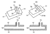
図5は、本発明の電子レンジ用包装袋の構造を示す説明図である。
図5(a)に示すように、シーラント層を上面とした下部材2と、上部材3aおよび上部材3bのシーラント層同士を対向させてウィング部4を形成し、シーラント層を下面とした上部材とを重ね合わせ、その周辺部をヒートシールして主シール部5を形成して密封した包装袋である。
なお、図5(b)に示すように、上部材3aおよび下部材2を1枚のシートから形成してもよい。
また、図示しないが、前記の樹脂層は、上部材1枚に形成してもよく、図5に示すように、上部材2枚に形成してもよい。
【0036】
ヒートシールの方法は、従来公知の方法を使用でき、例えば、加熱バー、加熱ナイフ、加熱ワイヤ、インパルスシールのような外部加熱方式、または超音波シール、誘電加熱シールのような内部加熱方式を使用できる。
【0037】
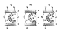
次に、本発明にかかる電子レンジ用包装袋の易開封加工部の形状について説明すると、図6は、前記の包装袋のウィング部の先端辺部に設けられる樹脂層形成領域の形状の一例を示す平面図である。
前記ウィング部内には、図6に示すように、耐熱性基材層とシーラント層の間に、室温以下の温度環境では所定の強度を有するが、高温の温度環境では前記の所定の強度が低下する性質を有する樹脂層を、シールしたウィング部の先端辺部の内側から外側に向かって少なくとも一領域、横断するように形成することが必要である。
前記の樹脂層の形成領域の形状としては、図6(a)に示すように、ウィング全体に設けてもよく、図6(b)および図6(c)に示すように、ウィングの一部に設けてもよい。
中でも、図6(c)に示すように、先端辺部を先細りの形状にすることにより、開封時に発生する音が軽減されるため、より好ましい。
【0038】
図7は、本発明の別態様の電子レンジ用包装袋(スタンディングパウチ)を示す図4のX2−X2部における断面図である。
図7(a)に示すように、胴部材7が、耐熱性基材層12とシーラント層16の間に、室温以下の温度環境では所定の強度を有するが、高温の温度環境では前記所定の強度が低下する樹脂層14を、耐熱性基材層12とシーラント層16の間に、胴部材7と底材8のシールした先端辺部の少なくとも一領域において、内側から外側に向かって横断するように形成するものである。
また、図7(b)に示すように、胴部材7が、前記の樹脂層14を耐熱性基材層12とシーラント層16の間に、胴部材7と底材8のシールした先端辺部の少なくとも一領域において、内側から外側に向かって横断するように形成するものであってもよい。
更に、図7(c)に示すように、胴部材7と底材8が、前記の樹脂層14を耐熱性基材層12とシーラント層16の間に、胴部材7と底材8のシールした先端辺部の少なくとも一領域において、内側から外側に向かって横断するように形成するものであってもよい。
【0039】
本発明において、上記のようにして製造した電子レンジ用包装袋は、例えば、冷凍しゅうまい等の固形食品、カレー、スープ、醤油、ソ−ス、出し汁、香辛料、料理用酒類、果汁類、水等の各種の流動性食品、飲食品を充填包装し得るものである。
【0040】
次に、本発明にかかる電子レンジ用包装袋を用いて、流動性食品等の内容物を充填した包装体について説明すると、図8は、本発明の電子レンジ用包装体の断面図である。
前記のウィング部を上側にし、横置して加熱すれば、内容物9が流動性食品等の場合でも漏れる心配がなく、好ましいものである。
【0041】
図9は、本発明の別態様の電子レンジ用包装袋(スタンディングパウチ)に流動性食品等の内容物を充填した包装体の断面図である。
スタンディングパウチを前記の樹脂層を設けた胴部を上側にし、横置して加熱すれば、内容物9が流動性食品等の場合でも漏れる心配がなく、好ましいものである。
【0042】
図10は、本発明の電子レンジ用包装袋に流動性食品等の内容物を充填した包装体のウィング部のシール部の(a)加熱前の状態と(b)加熱によって蒸気を放散する状態を示す拡大断面図である。
図11は、本発明の別態様の電子レンジ用包装袋(スタンディングパウチ)に流動性食品等の内容物を充填した包装体の胴部と底部のシール部の(a)加熱前の状態と(b)加熱によって蒸気を放散する状態を示す拡大断面図である。
図10、図11に示すように、本発明の電子レンジ用包装袋が電子レンジで加熱された際に発生した蒸気の熱と圧力によって、前記の樹脂層14が、選択的に破壊され、胴部と底部のシール部の下端から剥離が始まり、上端に向かって広がり、上端部に到達し、開口部が形成され、開口部から蒸気が放散して包装袋の内圧は、常圧に戻る。
【0043】
以上説明したごとく、本発明の電子レンジ用包装袋は、袋の上部にウィング部を設けたことによって、液体を含む内容物の包装袋であっても、電子レンジの過熱に際して、ウィング部を上にして袋を横置きにできる。
而して、ウィング部の上部に蒸気の逃げ口を形成することにより、袋が破裂することなく、流動性のある食品が漏れることなく、安定して十分に加熱できるものである。
更に、予め、蒸気の逃げ口を形成しなくても、前記の樹脂層を、シールしたウィング部の先端辺部の少なくとも一領域に、内側から外側に向かって横断するように形成することにより、袋が破裂することなく、蒸気の逃げ口の範囲、大きさ、量を制御することができ、開封時の音も小さくて済み、自動的で安定してスムーズに開口部から蒸気が放散して包装袋の内圧が常圧に戻ることができるものである。
【0044】
【実施例】
以下に実施例をあげて本発明を更に説明する。
(実施例1)
(1)下部材2および上部材の片側部材(図5(a)における3b)の作製
耐熱性基材層12として厚さ15μmの延伸ナイロンフィルムを用い、その上に、シーラント層16として50μmの直鎖状低密度ポリエチレンフィルムを用い、二液硬化型ポリウレタン接着剤を接着層15として用いて貼り合わせてドライラミネートし、下部材および上部材の片側部材(図5(a)における3b)を作製した。
(2)上部材の片側部材(図5(a)における3a)の作製
次に、耐熱性基材層12として厚さ15μmの延伸ナイロンフィルムを用い、その上に樹脂層14としてエチレン−酢酸ビニル共重合体樹脂(融点:66.8℃、WT−PC剤:ザ・インクテック株式会社製)を、厚さ3μmとなるようにパターンコートした。
さらにその上に、シーラント層16として50μmの直鎖状低密度ポリエチレンフィルムを用い、二液硬化型ポリウレタン接着剤を接着層15として用いて貼り合わせてドライラミネートし、上部材の他側部材(図5(a)における3a)を作製した。
(3)包装袋の作製
上記で得られた下部材2および上部材(図5(a)の3aおよび3b)を用いて、シール温度160℃、圧力1kg/秒、シール幅10mmで、図3に示すような包装袋(145mm×180mm)を作製した。
図3に示す各部位の寸法を次の通りとした。
a=35mm、b=145mm、c=35mm、d=145mm
(4)包装体の作製
この包装袋にカレー(150g)を入れ、得られた包装体をウィング部を上向きにして横置の状態で、500W電子レンジにて加熱した結果、約2分後にウィング部に設けた樹脂層コーティング部分から静かに蒸気が抜けた。
なお、蒸気は包装袋上部から抜けたので、図8に示すように内容物9のふきこぼれもなかった。
【0045】(実施例2)
(1)底材および胴部材の片側部材の作製
耐熱性基材層12として厚さ15μmの延伸ナイロンフィルムを用い、その上に、シーラント層16として50μmの直鎖状低密度ポリエチレンフィルムを用い、二液硬化型ポリウレタン接着剤を接着層15として用いて貼り合わせてドライラミネートし、底材および胴部材の片側部材を作製した。
(2)胴部材の他側部材の作製
次に、耐熱性基材層12として厚さ15μmの延伸ナイロンフィルムを用い、その上に樹脂層14としてエチレン−酢酸ビニル共重合体樹脂(融点:66.8℃、WT−PC剤:ザ・インクテック株式会社製)を、厚さ3μmとなるようにパターンコートした。
さらにその上に、シーラント層16として50μmの直鎖状低密度ポリエチレンフィルムを用い、二液硬化型ポリウレタン接着剤を接着層15として用いて貼り合わせてドライラミネートし、胴部材の他側部材を作製した。
(3)包装袋の作製
上記で得られた胴部材2枚および底材1枚を用いて、シール温度160℃、圧力1kg/秒、シール幅10mmで、図4に示すような包装袋(130mm×170mm)を作製した。
図4に示す各部位の寸法を次の通りとした。
e=145mm、f=25mm、g=130mm
(4)包装体の作製
この包装袋にカレー(150g)を入れ、得られた包装体をウィング部を上向きにして横置の状態で、500W電子レンジにて加熱した結果、約2分後に包装袋上部のシール部に設けた樹脂層コーティング部分から静かに蒸気が抜けた。
なお、蒸気は包装袋上部から抜けたので、図9に示すように内容物9のふきこぼれもなかった。
【0046】(実験1:シール強度測定)
実施例1および実施例2で製造した包装袋について、各々図12および図13に示す4個所の位置にて、サンプルを15mm巾の短冊切りし、23℃および90℃で、引張試験機(オリエンテック社製)でT字剥離して測定した。
なお、引張速度は、300mm/min、つまみ間隔50mm、ロ−ドセル5kgfで行った。
上記の測定結果について、下記の表1に示す。
なお、表1中には、15mm当たりのシール強度(単位:N/15mm)を記載した。
【0047】(実験結果)
【表1】

上記の測定結果より明らかなように、実施例1および実施例2にかかる包装袋は、常温23℃、すなわち食品等の包装工程時や流通過程での環境温度領域において必要なシール強度を保持し、90℃、すなわち電子レンジで加熱するときの環境温度領域において、ウィング部の樹脂を形成した部分のシール強度のみ低下して、その部分から内容物を包装したまま破裂を起こさず、内容物がこぼれることなく、開封音も静かで、短時間に内圧を低下させることができるものであった。
【0049】
【発明の効果】
以上の説明で明らかなように、本発明は、電子レンジにより加熱するための袋であって、耐熱性基材層とシーラント層の間に、室温以下の温度環境では所定の強度を有するが、高温の温度環境では前記所定の強度が低下する樹脂層を、少なくとも一領域設けた積層フィルムを用いる包装袋であって、かつ、シーラント面を上面とした下部材と、シーラント面同士を向かい合わせて側部と先端辺部とをシールしたウィング部を形成し、シーラント面を下面とした上部材とを重ね合わせ、その周縁部をシールして主シール部として密封した包装袋であって、前記のウィング部を構成する上部材の1枚又は2枚が、前記の樹脂層を、シールしたウィング部の先端辺部の少なくとも一領域に、内側から外側に向かって横断するように形成してなることを特徴とする電子レンジ用包装袋を製造したところ、輸送や保管をするときに加わる圧力や衝撃によって剥離することなく、電子レンジで加熱するときに内容物を包装したまま破裂を起こさず、開封音も静かで、自動的に安定して内圧を低下させることができ、袋を横置に載置したまま、従来の固形食品に加えて、流動性食品等の内容物についても、こぼれることのない優れた電子レンジ用包装袋を提供することができるものである。
【図面の簡単な説明】
【図1】本発明の電子レンジ用包装袋に用いられる包装材料10の一例を示す断面図である。
【図2】本発明の電子レンジ用包装袋のシールしたウィング部の先端辺部の一例を示す拡大断面図である。
【図3】本発明の電子レンジ用包装袋の一例を示す斜視図である。
【図4】本発明の別態様の電子レンジ用包装袋の一例を示す斜視図である。
【図5】本発明の電子レンジ用包装袋の構造を示す説明図、及び、そのX1−X1部における断面図である。
【図6】本発明の電子レンジ用包装袋のウィング部の先端辺部に設けられる樹脂層形成領域の形状の一例を示す平面図である。
【図7】図4のX2−X2部の断面図である。
【図8】本発明の電子レンジ用包装袋に内容物を充填した包装体の断面図である。
【図9】本発明の別態様の電子レンジ用包装袋に内容物を充填した包装体の断面図である。
【図10】本発明の電子レンジ用包装袋に流動性食品等の内容物を充填した包装体のウィング部のシール部の(a)加熱前の状態と(b)加熱によって蒸気を放散する状態を示す拡大断面図である。
【図11】図9の包装体の胴部と底部のシール部の(a)加熱前の状態と(b)加熱によって蒸気を放散する状態を示す拡大断面図である。
【図12】実施例1の電子レンジ用包装袋のシール強度測定の位置を説明する図である。
【図13】実施例2の電子レンジ用包装袋のシール強度測定の位置を説明する図である。
【符号の説明】
1 電子レンジ用包装袋
2 下部材
3a 上部材
3b 上部材
4 ウィング部
5 主シール部
5G ガイドシール部
6S サイドシール部
6B ボトムシール部
7 胴部材
8 底材
9 内容物
10 包装材料(積層体)
12 耐熱性基材層
13 印刷層
14 樹脂層
15 接着層
16 シーラント層
16a 樹脂層を形成した上部材のシーラント
17 中間層
22 シール部分
23 破壊の起点となる任意の個所
24 破壊する仮想線
32 樹脂層形成領域[0001]
TECHNICAL FIELD OF THE INVENTION
The present invention is capable of automatically lowering the internal pressure without peeling due to pressure or impact applied during transportation or storage, and without causing rupture while packaging the contents when heated in a microwave oven. The present invention relates to a packaging bag for a microwave oven that can be made.
More specifically, as contents, in addition to solid foods, for example, liquid foods such as curries and soups, and various foods and drinks such as drinking water are hermetically sealed and packaged, and the contents are placed in a horizontal bag. The present invention relates to a packaging bag for a microwave oven that can be safely heated without spilling.
[0002]
[Prior art]
In recent years, due to the spread and development of microwave ovens and the demand for simplified cooking, cooked processed foods are distributed in a form that is packaged in plastic packaging bags, sealed, and preserved. ing.
When such a food is heated in a microwave oven, if the packaging bag is kept sealed, the internal pressure in the bag increases due to steam generated from the content due to the heating, and eventually the container bursts, and the content is microwaved. It is known that it will scatter inside. In order to prevent such rupture of the packaging bag, as a conventional packaging container, for example, a packaging container in which a part of the packaging bag is cut with scissors to form a vent before heating in a microwave oven. (For example, see Patent Document 1).
In addition, in order to avoid a situation in which the consumer forgets the operation of forming the above-mentioned vent before heating, and avoids a situation in which the bag is ruptured by heating, various packages that can automatically vent the steam are used. A container has been proposed.
There is a packaging container in which a through-hole for degassing is formed along with a release agent applied on a sealing surface of a plastic container due to an increase in the internal pressure of the container when heated in a microwave oven (for example, see Patent Document 2). ).
There is also a packaging container in which similar through-pores are formed on a sealing surface along a release agent layer provided between a heat-resistant thermoplastic resin layer and a sealant film (for example, see Patent Document 3). ).
[0003]
[Patent Document 1]
JP-A-10-72070 (page 2-3, FIG. 3)
[Patent Document 2]
JP-A-9-40030 (page 4, FIG. 6)
[Patent Document 3]
JP-A-9-272180 (pages 3-4, FIG. 4)
[0004]
[Problems to be solved by the invention]
However, before heating in a microwave oven, a part of the packaging bag is cut off with scissors to form a vent, which is troublesome and troublesome, and before heating by a consumer, Forgetting the work of forming the air vent of the bag, there is a danger that the bag may burst by heating, which is very dangerous.
Further, in the case of a packaging container in which a release agent is applied on the sealing surface, since the above-mentioned release agent is originally formed to facilitate peeling, pressure or impact applied during normal transportation or storage is used. There was a risk of peeling off from the sealing surface.
Further, the above-mentioned one in which the application surface of the release agent is formed so as to protrude from the seal portion is not preferable because the release agent comes into contact with the contents.
For this reason, conventionally, complicated processes such as devising the pattern shape of the release agent layer so as to withstand impact during transportation, and forming the release agent layer with high precision so as not to protrude from the seal portion are required. There was a problem.
[0005]
Further, prior to the present application, the applicant has a resin between the heat-resistant base material layer and the sealant layer, which has a predetermined strength in a temperature environment of room temperature or lower, but softens in a high-temperature environment and decreases in strength. Using a packaging material provided with a layer, an attempt was made to produce a packaging bag for a microwave oven.
Since this microwave packaging bag is provided with the above resin layer in a part of the seal portion, it is opened by an increase in internal pressure caused by heating in the microwave oven, and the pressure in the packaging bag is automatically released. Was possible.
[0006]
However, although the packaging bag for microwave ovens is a packaging bag capable of accommodating solid foods, the contents of liquid foods such as curry, and foods and beverages such as drinking water before opening the bag. Because of the risk of spilling, it could not be used as a food or beverage packaging bag containing liquids such as fluid foods.
[0007]
[Means for Solving the Problems]
Therefore, the present inventors have conducted intensive studies to solve the above-described problems, and as a result, the present invention is a bag for heating with a microwave oven, and a room temperature between a heat-resistant base material layer and a sealant layer. In the following temperature environment has a predetermined strength, but in a high temperature environment is a packaging bag using a laminated film provided with at least one area of the resin layer in which the predetermined strength is reduced, and the sealant surface is the upper surface A main seal portion is formed by forming a lower member and a wing portion in which the sealant surfaces face each other to seal a side portion and a tip side portion, and an upper member having a sealant surface as a lower surface, and sealing a peripheral portion thereof. Wherein one or two of the upper members constituting the wing portion are formed by applying the resin layer to at least one region of the tip side of the sealed wing portion from the inside to the outside. Opposite When manufacturing a packaging bag for a microwave oven characterized by being formed so as to traverse, it is not necessary to make the precision of the pattern formation of the resin layer severe, the pattern can be easily formed, Excellent in sealing strength at room temperature or lower, that is, in the environmental temperature range during the packaging process of foods and during freezing after packaging, without spilling the contents, and bursting while heating the contents in a microwave oven while packaging the contents The internal pressure can be automatically reduced without causing any problems.In addition to solid foods, various foods and beverages such as fluid foods are sealed and packaged, and the contents are stored while the bag is placed horizontally. It has been found that a packaging bag for a microwave oven that can be safely heated without spilling can be produced.
In the above, according to the present invention, the sealing strength in the region of the tip side of the wing portion provided with the resin layer is 10 N / 15 mm or less in a high temperature region of 80 ° C. or higher. A range packaging bag can be provided.
Further, it is possible to provide a packaging bag for a microwave oven, characterized in that the ratio of the length from the end to the wing and the length from the wing to the other end of the packaging bag is 2/3 or less.
[0008]
BEST MODE FOR CARRYING OUT THE INVENTION
Hereinafter, the present invention will be described specifically.
FIG. 1 is a sectional view showing an example of a
FIG. 2 is an enlarged cross-sectional view showing an example of a tip side of a sealed wing portion of the packaging bag for a microwave oven according to the present invention.
3 and 4 are perspective views showing an example of the packaging bag for a microwave oven according to the present invention. FIG. 5 is an explanatory view showing the structure of the packaging bag for a microwave oven of the present invention, and FIG. 1 -X 1 FIG. 6 is a plan view showing an example of a shape of a resin layer forming region provided at a tip side portion of a wing portion.
FIG. 2 -X 2 It is sectional drawing of a part.
8 and 9 are cross-sectional views of a package in which contents are filled in a packaging bag for a microwave oven according to the present invention.
10 and 11 are enlarged cross-sectional views showing (a) a state before heating and (b) a state in which steam is dissipated by heating of the seal portion of the wing portion of the package of FIGS. 8 and 9.
[0009]
First, each member forming the packaging bag for a microwave oven according to the present invention will be described.
FIG. 1 is a cross-sectional view showing an example of a
As shown in FIG. 1A, the
In addition, the
Therefore, the packaging material used in the present invention is a laminate having at least the
[0010]
Further, as shown in FIG. 1B, the
In addition, the
[0011]
The heat-resistant
The heat-
For example, stretched polyethylene terephthalate film, silica-deposited polyethylene terephthalate film, alumina-deposited polyethylene terephthalate film, stretched nylon film, silica-deposited stretched nylon film, alumina-deposited stretched nylon film, stretched polypropylene film, polyvinyl alcohol-coated stretched polypropylene film,
These heat-resistant resin layers 12 have a melting point of usually 150 ° C. or higher and a thickness of 10 to 50 μm.
[0012]
The
Usually, as shown in FIG. 1, the printed
[0013]
The
The
[0014]
The temperature at or below room temperature at which the predetermined strength is maintained is generally defined as the environmental temperature during the step of packaging the contents such as food using the
Therefore, the
On the other hand, the high-temperature environment in which the predetermined strength is reduced is a temperature applied when a packaging bag or a container in which contents such as food are hermetically sealed is heated or cooked in a microwave oven. As a result, the strength of the
[0015]
In the present invention, the
The strength of the
[0016]
FIG. 2 is an enlarged cross-sectional view showing an example of the tip side of the sealed wing portion of the
As shown in the enlarged cross-sectional view of the sealing
As a result, between the
In the present invention, since the destruction occurs partially, air leakage of a relatively small size occurs, the internal pressure of the
[0017]
As the
The use of the resin layer having a melting point of 60 to 90 ° C. has an advantage that a partial breakage of the
[0018]
The
If the thickness of the
If the thickness of the
[0019]
When the
Since the sealing strength of the area where the
Further, in a high temperature range of 80 ° C. or more, the temperature is 10 (N / 15 mm) or less, so that the
Since the packaging bag made of the packaging material having such characteristics can adjust the sealing strength in that range, it is adjusted so that it is partially broken only when heated by a microwave oven and the internal pressure rises to a certain degree. It has the advantage that.
[0020]
The
As the
The sealant layer may be formed by extruding and laminating these resins, or may be formed in advance as a film formed by a T-die method, an inflation method, or the like.
The thickness of these sealant layers 16 is usually preferably from 20 to 100 μm, more preferably from 30 to 60 μm.
In the present invention, when the packaging bag is manufactured, the sealant layers 16 form a sealing surface at the sealed portion of the packaging bag. No sealing surface is formed, so that the bonded sealing surface is not broken at the time of freezing, transportation, storage, etc., and the contents are not exposed.
[0021]
As the strength of the
Therefore, as shown in FIG. 2, the
[0022]
Further, the
For example, as shown in FIG. 2, the thickness of the sealant 16a of one upper member forming the resin layer between the heat-resistant base material layer and the sealant layer is made thinner than the sealants of the other upper and lower members. Is preferred.
Further, only the material of the sealant 16a of one upper member has a property that is excellent in tear strength, such as low-density polyethylene, a comonomer linear low-density polyethylene having 4 carbon atoms (hereinafter referred to as "C4LLDPE"). It is preferable to use a sealant, and among them, C4LLDPE is more preferable because it has excellent sealing properties.
In the above, when the
[0023]
As the
For example, as the oxygen barrier layer, a vinylidene chloride film, an ethylene-vinyl alcohol copolymer film, or an inorganic vapor-deposited film can be used.
As the shock absorbing resin layer, a nylon film is preferably used.
As the nylon film, any one of uniaxial stretching, biaxial stretching and non-stretching can be suitably used.
The thickness of the shock absorbing resin layer is not particularly limited, but is usually in the range of 5 to 40 μm, preferably 10 to 30 μm.
However, even when such an intermediate layer is provided, providing the
[0024]
Known additives such as a lubricant, an antioxidant, an antistatic agent, and a coloring agent can be added to the resin forming each layer of the packaging material as needed without impairing the achievement of the object of the present invention.
The addition amount can be arbitrarily added from a very small amount to several tens% depending on the purpose.
[0025]
Next, in the present invention, a method for manufacturing a laminate using the above-described materials will be described. Examples of the method include a heat-resistant
[0026]
In the above, as the laminating adhesive, for example, a one-component or two-component curing or non-curing type vinyl, (meth) acrylic, polyamide, polyester, polyether, polyurethane, epoxy, etc. Adhesives for lamination such as solvent-based, water-based, and emulsion-based adhesives, and rubber-based adhesives and the like can be used.
As a coating method of the above-mentioned laminating adhesive, for example, direct gravure roll coating method, gravure roll coating method, kiss coating method, reverse roll coating method, Fonten method, transfer roll coating method, can be applied by other methods .
The coating amount is 0.1 to 10 g / m 2 (Dry state) is preferable, and 1 to 5 g / m 2 (Dry state) is more preferable.
[0027]
In the above description, a resin layer composed of a thermoplastic resin layer is used as the melt-extrudable resin layer, and can be used for bonding each layer.
Specifically, as the material of the adhesive melt-extrudable resin layer, low-density polyethylene resin, medium-density polyethylene resin, high-density polyethylene resin, linear low-density polyethylene resin, ethylene polymerized using a metallocene catalyst,・ Copolymer resin with α-olefin, ethylene / polypropylene copolymer resin, ethylene / vinyl acetate copolymer resin, ethylene / acrylic acid copolymer resin, ethylene / ethyl acrylate copolymer resin, ethylene / methacrylic acid Copolymer resin, ethylene / methyl methacrylate copolymer resin, ethylene / maleic acid copolymer resin, ionomer resin, polyolefin resin, unsaturated carboxylic acid, unsaturated carboxylic acid, unsaturated carboxylic anhydride, ester monomer Grafted or copolymerized resin, maleic anhydride to polyolefin It can be used a graft modified resin or the like fat. These materials can be used alone or in combination of two or more.
The thickness of the resin layer is preferably about 10 to 30 μm.
[0028]
In the case of performing the above-mentioned lamination, if necessary, for example, a pretreatment such as a corona treatment, an ozone treatment, a framing treatment and the like can be performed, and the lamination can be performed.
The above-mentioned surface pretreatment, when laminating each layer with a film or sheet of various resins, is to be carried out as a method for improving the adhesion, etc., as a method for improving the adhesion, for example, A surface treatment layer can also be formed by arbitrarily forming a primer coating agent layer, an undercoating agent layer, an anchor coating agent layer, and the like on the surface of various resin films or sheets in advance.
[0029]
As the coating agent layer for the above pretreatment, for example, polyester resin, polyamide resin, polyurethane resin, epoxy resin, phenol resin, (meth) acrylic resin, polyvinyl acetate resin, polyethylene or polypropylene, etc. A resin composition containing a polyolefin-based resin or a copolymer or modified resin thereof, a cellulose-based resin, or the like as a main component of the vehicle can be used.
[0030]
The
[0031]
Next, various modes of the packaging bag for a microwave oven of the present invention will be described. FIG. 3 is a perspective view showing an example of the packaging bag for a microwave oven of the present invention.
As shown in FIG. 3, the packaging bag for a microwave oven of the present invention is a bag provided with a wing portion on one side of the bag.
Thus, the packaging bag for a microwave oven of the present invention can be heated by a microwave oven as the upper surface provided with the wing portion.
[0032]
As shown in FIG. 3, the position of the wing portion in the packaging bag for a microwave oven of the present invention is offset from the edge of the packaging bag, from the end of the packaging bag to the wing portion a, and from the wing portion to the other end. It is desirable that the ratio of the length up to the portion b is 2/3 or less.
If the distance exceeds 2/3, a preferable automatic opening cannot be performed when heating with a microwave oven.
[0033]
As shown in FIG. 3, since the sound at the time of opening tends to be reduced when the width of the steam port is narrow, a
[0034]
FIG. 4 is a perspective view showing an example of a packaging bag for a microwave oven according to another embodiment of the present invention.
As shown in FIG. 4, the packaging bag for a microwave oven according to the present invention may be a bag whose main body is formed in a standing pouch shape composed of a trunk material and a bottom material.
As shown in FIG. 4, the lower member having the sealant layer on the upper surface and the upper member having the sealant layer on the lower surface are overlapped, and both ends of the body are heat-sealed. It is a packaging bag in which the periphery of the bottom material is heat-sealed so that it can be standing.
At the stage of making the packaging bag, the packaging bag is not heat-sealed but is in an open state, and the contents are filled from this portion.
[0035]
FIG. 5 is an explanatory view showing the structure of the packaging bag for a microwave oven of the present invention.
As shown in FIG. 5A, the
As shown in FIG. 5B, the
Although not shown, the resin layer may be formed on one upper member, or may be formed on two upper members as shown in FIG.
[0036]
For the method of heat sealing, a conventionally known method can be used, for example, an external heating method such as a heating bar, a heating knife, a heating wire, an impulse seal, or an internal heating method such as an ultrasonic seal or a dielectric heating seal is used. it can.
[0037]
Next, the shape of the easily opened portion of the packaging bag for a microwave oven according to the present invention will be described. FIG. 6 shows an example of the shape of the resin layer forming region provided at the tip side of the wing portion of the packaging bag. FIG.
As shown in FIG. 6, the wing portion has a predetermined strength between the heat-resistant base material layer and the sealant layer in a temperature environment of room temperature or lower, but the predetermined strength is reduced in a high temperature environment. It is necessary to form a resin layer having such properties as to cross at least one region from the inside to the outside of the tip side of the sealed wing.
The shape of the region where the resin layer is formed may be provided on the entire wing as shown in FIG. 6A, or a part of the wing as shown in FIGS. 6B and 6C. May be provided.
In particular, as shown in FIG. 6 (c), it is more preferable that the tip side is tapered so that the sound generated at the time of opening is reduced.
[0038]
FIG. 7 is a cross-sectional view illustrating a packaging bag (standing pouch) for a microwave oven according to another embodiment of the present invention. 2 -X 2 It is sectional drawing in a part.
As shown in FIG. 7A, the
Further, as shown in FIG. 7B, the
Further, as shown in FIG. 7 (c), the
[0039]
In the present invention, the packaging bag for a microwave oven produced as described above includes, for example, solid foods such as frozen sweet potato, curry, soup, soy sauce, sauce, broth, spices, cooking alcohol, fruit juice, water, etc. Of various fluid foods, foods and beverages.
[0040]
Next, a package filled with contents such as fluid food using the packaging bag for a microwave oven according to the present invention will be described. FIG. 8 is a sectional view of the package for a microwave oven of the present invention.
If the wing portion is placed on the upper side and heated sideways, there is no fear that the
[0041]
FIG. 9 is a cross-sectional view of another embodiment of the present invention in which a packaging bag (standing pouch) for a microwave oven is filled with contents such as a flowable food.
If the standing pouch is heated sideways with the body provided with the resin layer facing upward, there is no fear that the
[0042]
FIG. 10 shows (a) a state before heating and (b) a state in which steam is diffused by heating of a seal portion of a wing portion of a package in which contents such as a flowable food are filled in a packaging bag for a microwave oven of the present invention. FIG.
FIG. 11 shows (a) a state before heating (a) of a body and a bottom seal portion of a package in which contents such as a flowable food are filled in a microwave packaging bag (standing pouch) according to another embodiment of the present invention; b) It is an enlarged sectional view showing a state in which steam is diffused by heating.
As shown in FIGS. 10 and 11, the
[0043]
As described above, the packaging bag for a microwave oven of the present invention has a wing portion provided on the upper portion of the bag, so that even if the packaging bag contains contents containing a liquid, the wing portion rises when the microwave oven is overheated. You can put the bag horizontally.
Thus, by forming a steam vent at the upper portion of the wing portion, the bag can be stably and sufficiently heated without bursting of the bag and leakage of fluid food.
Furthermore, by forming the resin layer in at least one region of the tip side of the sealed wing portion from the inside to the outside without forming a steam escape port in advance, The range, size, and volume of the steam vent can be controlled without the bag exploding, and the sound at the time of opening is small, and the steam is automatically, stably and smoothly released from the opening. The internal pressure of the packaging bag can return to normal pressure.
[0044]
【Example】
Hereinafter, the present invention will be further described with reference to examples.
(Example 1)
(1) Production of
A stretched nylon film having a thickness of 15 μm is used as the heat-resistant
(2) Fabrication of one side member (3a in FIG. 5A) of the upper member
Next, a stretched nylon film having a thickness of 15 μm is used as the heat-resistant
Furthermore, a 50 μm linear low-density polyethylene film is used as the
(3) Preparation of packaging bag
Using the
The dimensions of each part shown in FIG. 3 were as follows.
a = 35 mm, b = 145 mm, c = 35 mm, d = 145 mm
(4) Preparation of package
Curry (150 g) was put into the packaging bag, and the obtained package was heated in a 500 W microwave oven with the wings facing upward, and the resin layer coating provided on the wings after about 2 minutes Steam gently escaped from the area.
In addition, since the steam escaped from the upper part of the packaging bag, the
(Embodiment 2)
(1) Production of one side member of bottom material and body member
A stretched nylon film having a thickness of 15 μm is used as the heat-resistant
(2) Production of the other side member of the trunk member
Next, a stretched nylon film having a thickness of 15 μm is used as the heat-resistant
Furthermore, a 50 μm linear low-density polyethylene film is used as the
(3) Preparation of packaging bag
A packaging bag (130 mm × 170 mm) as shown in FIG. 4 was produced using two body members and one bottom material obtained above at a sealing temperature of 160 ° C., a pressure of 1 kg / sec, and a sealing width of 10 mm.
The dimensions of each part shown in FIG. 4 were as follows.
e = 145 mm, f = 25 mm, g = 130 mm
(4) Preparation of package
Curry (150 g) was put in this packaging bag, and the obtained package was heated in a 500 W microwave oven with the wings facing upward and placed sideways. Steam gently escaped from the resin layer coating.
Since the steam escaped from the upper part of the packaging bag, the
(Experiment 1: Seal Strength Measurement)
The packaging bags manufactured in Examples 1 and 2 were cut into strips of 15 mm width at four positions shown in FIGS. 12 and 13, respectively, and were subjected to a tensile tester (Oriental Corporation) at 23 ° C. and 90 ° C. And T-peeling.
The tensile speed was 300 mm / min, the distance between the knobs was 50 mm, and the load cell was 5 kgf.
The above measurement results are shown in Table 1 below.
Table 1 shows the seal strength per 15 mm (unit: N / 15 mm).
(Experimental results)
[Table 1]
As is clear from the above measurement results, the packaging bags according to Example 1 and Example 2 maintain the necessary sealing strength at room temperature of 23 ° C., that is, in the environmental temperature range during the packaging process of food or the like or during the distribution process. , 90 ° C., that is, in the environment temperature range when heating in a microwave oven, only the sealing strength of the resin-formed portion of the wing portion is reduced, and the content is not ruptured while packaging the content from that portion. Without opening, the opening sound was quiet and the internal pressure could be reduced in a short time.
[0049]
【The invention's effect】
As is clear from the above description, the present invention is a bag for heating with a microwave oven, between a heat-resistant base material layer and a sealant layer, having a predetermined strength in a temperature environment of room temperature or less, In a high temperature environment, the predetermined strength is reduced, the resin layer is a packaging bag using a laminated film provided in at least one region, and the lower member with the sealant surface as the upper surface, the sealant surfaces face each other. A packaging bag in which a wing portion in which a side portion and a tip side portion are sealed is formed, an upper member having a sealant surface as a lower surface is overlapped, and a peripheral portion thereof is sealed to be sealed as a main seal portion. One or two of the upper members constituting the wing portion are formed by traversing the resin layer in at least one region of the tip side of the sealed wing portion from inside to outside. When the packaging bag for microwave ovens is manufactured, it does not peel off due to the pressure or impact applied during transportation or storage, does not burst when the contents are packaged when heated in a microwave oven, and does not open. It is also quiet, can automatically reduce the internal pressure automatically and stably, without spilling on the contents such as fluid foods in addition to conventional solid foods while the bag is placed horizontally. It is possible to provide an excellent packaging bag for a microwave oven.
[Brief description of the drawings]
FIG. 1 is a sectional view showing an example of a
FIG. 2 is an enlarged cross-sectional view showing an example of a tip side portion of a sealed wing portion of the packaging bag for a microwave oven of the present invention.
FIG. 3 is a perspective view showing an example of a packaging bag for a microwave oven according to the present invention.
FIG. 4 is a perspective view showing an example of a packaging bag for a microwave oven according to another embodiment of the present invention.
FIG. 5 is an explanatory view showing the structure of a packaging bag for a microwave oven according to the present invention, and its X. 1 -X 1 It is sectional drawing in a part.
FIG. 6 is a plan view showing an example of a shape of a resin layer forming region provided at a tip side of a wing portion of the packaging bag for a microwave oven of the present invention.
FIG. 7 is a diagram showing an X in FIG. 2 -X 2 It is sectional drawing of a part.
FIG. 8 is a cross-sectional view of a package in which contents are filled in a packaging bag for a microwave oven of the present invention.
FIG. 9 is a cross-sectional view of a package in which contents are filled in a microwave packaging bag according to another embodiment of the present invention.
FIG. 10 is a view showing a state before (a) heating and (b) a state in which steam is released by heating of a seal portion of a wing portion of a package in which contents such as a flowable food are filled in a packaging bag for a microwave oven of the present invention. FIG.
11 is an enlarged cross-sectional view showing (a) a state before heating and (b) a state in which steam is dissipated by heating of the body and bottom seal portions of the package of FIG. 9;
FIG. 12 is a view for explaining positions for measuring the seal strength of the packaging bag for a microwave oven of Example 1.
FIG. 13 is a view for explaining a position for measuring the seal strength of the packaging bag for a microwave oven of Example 2.
[Explanation of symbols]
1 Packaging bag for microwave oven
2 Lower member
3a Upper member
3b Upper member
4 Wing club
5 Main seal part
5G guide seal
6S side seal
6B Bottom seal part
7 torso members
8 Bottom material
9 Contents
10 Packaging materials (laminate)
12 Heat-resistant base material layer
13 Printing layer
14 Resin layer
15 Adhesive layer
16 Sealant layer
16a Sealant for upper member with resin layer formed
17 Middle class
22 Seal part
23 Arbitrary place that becomes the starting point of destruction
24 Virtual line to destroy
32 resin layer formation area
Claims (3)
Priority Applications (1)
| Application Number | Priority Date | Filing Date | Title |
|---|---|---|---|
| JP2002269529A JP2004106863A (en) | 2002-09-17 | 2002-09-17 | Packaging bag for use in microwave oven |
Applications Claiming Priority (1)
| Application Number | Priority Date | Filing Date | Title |
|---|---|---|---|
| JP2002269529A JP2004106863A (en) | 2002-09-17 | 2002-09-17 | Packaging bag for use in microwave oven |
Publications (1)
| Publication Number | Publication Date |
|---|---|
| JP2004106863A true JP2004106863A (en) | 2004-04-08 |
Family
ID=32267434
Family Applications (1)
| Application Number | Title | Priority Date | Filing Date |
|---|---|---|---|
| JP2002269529A Pending JP2004106863A (en) | 2002-09-17 | 2002-09-17 | Packaging bag for use in microwave oven |
Country Status (1)
| Country | Link |
|---|---|
| JP (1) | JP2004106863A (en) |
Cited By (6)
| Publication number | Priority date | Publication date | Assignee | Title |
|---|---|---|---|---|
| JP2006062672A (en) * | 2004-08-25 | 2006-03-09 | Toyo Seikan Kaisha Ltd | Plastic pouch |
| JP2007223626A (en) * | 2006-02-22 | 2007-09-06 | Dainippon Printing Co Ltd | Packaging bag for use in microwave |
| JP2008273538A (en) * | 2007-04-25 | 2008-11-13 | Kyodo Printing Co Ltd | Microwave heatable packaging bag |
| JP2013043668A (en) * | 2011-08-23 | 2013-03-04 | Dainippon Printing Co Ltd | Deep drawing packaging material with spontaneous unsealing function corresponding to microwave oven cooking |
| JP2018172150A (en) * | 2017-03-31 | 2018-11-08 | 大日本印刷株式会社 | Packaging bag for microwave oven and laminate body |
| JP2020192999A (en) * | 2019-05-28 | 2020-12-03 | 大日本印刷株式会社 | Bag material, bag and package |
-
2002
- 2002-09-17 JP JP2002269529A patent/JP2004106863A/en active Pending
Cited By (6)
| Publication number | Priority date | Publication date | Assignee | Title |
|---|---|---|---|---|
| JP2006062672A (en) * | 2004-08-25 | 2006-03-09 | Toyo Seikan Kaisha Ltd | Plastic pouch |
| JP2007223626A (en) * | 2006-02-22 | 2007-09-06 | Dainippon Printing Co Ltd | Packaging bag for use in microwave |
| JP2008273538A (en) * | 2007-04-25 | 2008-11-13 | Kyodo Printing Co Ltd | Microwave heatable packaging bag |
| JP2013043668A (en) * | 2011-08-23 | 2013-03-04 | Dainippon Printing Co Ltd | Deep drawing packaging material with spontaneous unsealing function corresponding to microwave oven cooking |
| JP2018172150A (en) * | 2017-03-31 | 2018-11-08 | 大日本印刷株式会社 | Packaging bag for microwave oven and laminate body |
| JP2020192999A (en) * | 2019-05-28 | 2020-12-03 | 大日本印刷株式会社 | Bag material, bag and package |
Similar Documents
| Publication | Publication Date | Title |
|---|---|---|
| JP2007191199A (en) | Packaging bag for use in microwave oven | |
| US20050255200A1 (en) | Food packaging bag, food-packaged body, and method for manufacturing the same | |
| US7582340B2 (en) | Container for retort pouch food | |
| JP2007137472A (en) | Packaging bag for use in microwave oven | |
| JP2006327590A (en) | Self-standing packaging bag for microwave oven | |
| JP2006321493A (en) | Packaging bag for use in microwave oven | |
| JP3908529B2 (en) | Microwave packaging bag | |
| JP2005059872A (en) | Packaging bag for use in microwave oven | |
| JP4139659B2 (en) | Microwave oven packaging bag | |
| GB2360038A (en) | Heat sealable polymeric films | |
| JP2004115053A (en) | Packaging material for use in microwave oven and packaging bag employing the same | |
| JP4508723B2 (en) | Microwave oven packaging bag | |
| JP4366772B2 (en) | Packaging for microwave oven | |
| JP4184743B2 (en) | Microwave oven packaging bag | |
| JP5140921B2 (en) | Microwave packaging bag | |
| JP2004106863A (en) | Packaging bag for use in microwave oven | |
| JP4450639B2 (en) | Microwave cooking bag | |
| JP2007131302A (en) | Packaging bag for use in microwave oven | |
| JP4713091B2 (en) | Microwave oven packaging bag | |
| JP2000190912A (en) | Packaging material conforming to microwave oven, packaging bag and container using the same | |
| JP4334923B2 (en) | Microwave packaging bag | |
| JP5733809B1 (en) | Packaging materials, packaging bags, packaging containers and packages | |
| JP2005088971A (en) | Packaging bag for use in microwave oven | |
| JP2005088966A (en) | Packaging bag for use in microwave oven | |
| JP2003182778A (en) | Packaging bag for use in microwave oven |
Legal Events
| Date | Code | Title | Description |
|---|---|---|---|
| A621 | Written request for application examination |
Free format text: JAPANESE INTERMEDIATE CODE: A621 Effective date: 20050914 |
|
| A977 | Report on retrieval |
Free format text: JAPANESE INTERMEDIATE CODE: A971007 Effective date: 20080425 |
|
| A131 | Notification of reasons for refusal |
Free format text: JAPANESE INTERMEDIATE CODE: A131 Effective date: 20080430 |
|
| A02 | Decision of refusal |
Free format text: JAPANESE INTERMEDIATE CODE: A02 Effective date: 20080902 |