【0001】
【発明の属する技術分野】
本発明は、ナトリウム−硫黄電池の正極構造に関するものであり、より詳細には、二次電池として電力貯蔵、非常用電源、無停電電源などに利用されるナトリウム−硫黄電池の正極構造に関するものである。
【0002】
【従来の技術】
最近、昼夜間電力平準化または夜間電力の利用を目的に、また非常用ないし無停電用としての、活物質利用率と充放電効率が高いナトリウム−硫黄電池の開発が盛んに行われている。ナトリウム−硫黄電池は、一般に、筒状(チューブ或いは深掘コップ)に形成した固体電解質管内に、負極活物質が収容され、その外側に陽極活物質が配される。負極活物質はナトリウムを含み、固体電解質管はナトリウムイオン等を透過させるβ−アルミナ等からなる。陽極活物質には硫黄が使用され、硫黄は導電性を有する陽極用導電体に含浸されて分散収容されている。また陽極用導電体は、固体電解質管を使用する場合、断面が略ドーナツ形状の中空体に成形されるか或いは複数のパーツから組み合わせられ、この導電体はグラファイト繊維やカーボン繊維などからなる。
【0003】
ナトリウム−硫黄電池の正極構造において、放電時にはナトリウムと硫黄が反応して正極室内に多硫化ナトリウムを生成し、充電時には正極室内の多硫化ナトリウムから可逆的にナトリウム及び硫黄が生成するか、或いは硫黄リッチな多硫化ナトリウムが多くなる。
即ち、負極活物質であるナトリウム(Na)がナトリウムイオン(Na+)と電子(e−)とに分かれ、ナトリウムイオン(Na+)は固体電解質壁を透過して正極活物質中に侵入し、電子(e−)は負極集電体等から外部回路に流れる。正極における放電反応は、正極活物質中に侵入したナトリウムイオン(Na+)が硫黄(S)と反応して、多硫化ナトリウム(Na2Sx)を生成する。
ナトリウム−硫黄電池の充電時には、放電反応と逆の反応が起こり、ナトリウム(Na)および硫黄(S)が生成する。通常は、多硫化ナトリウム(Na2Sx)の一部が残留する程度まで充電する。これは、硫黄(S)よりも多硫化ナトリウム(Na2Sx)の固有抵抗が低いために、多硫化ナトリウム(Na2Sx)を残存させておけば正極活物質の抵抗の上昇を抑えることができるからである。
【0004】
ところで、充電時において所定の厚みを有する導電体中で生成したナトリウムイオンは固体電解質壁側に移動するため、導電体内において固体電解質壁の近傍で反応が起こり易くなり、結果として、その近傍が硫黄リッチに成り易くなる。硫黄リッチな多硫化ナトリウムは導電率が低下するため内部抵抗の増加を引き起こし、更なる外側の導電体内に生成したナトリウムイオンの移動を妨げ、その結果、充放電効率の低下を招くという問題がある。
【0005】
そこで、このような充放電率の低下を防止するため導電体の改良が提案されている。例えば、カーボン繊維織布が積層されるとともに、ニードルパンチが施されて形成され、カーボン繊維織布の繊維径が固体電解質壁から外側に向かうに従って次第に細くなるように構成した導電体等を使用したナトリウム−硫黄電池が提案されている(例えば、特許文献1参照。)。また、導電体としてのカーボン繊維織布を、厚さの異なる複数の織布で構成し、厚さの厚い織布を外側に組み込んだもの、更に、複数のカーボン繊維織布の厚さ方向に配向する繊維の割合を、外側ほど高くなるように設定したものも提案されている。
【0006】
また、耐硫黄及び多硫化ナトリウムに優れ、電子伝導性の低い物質層を固体電解質と電子導電体の間に接着して配置されたものが提案されている(例えば、特許文献2参照。)。
これらの従来の導電体を使用したナトリウム−硫黄電池では、その導電体の製造も煩雑であり、また正極自体の抵抗増加の抑制をするものではなく、充放電効率を改善するものではない。また活物質利用率が制限されるので、エネルギー密度を高めることもできない。
【0007】
【特許文献1】
特開平8−31451号公報(特許請求の範囲の請求項1)
【特許文献2】
特開平9−35741号公報(第1頁)
【0008】
【発明が解決しようとする課題】
本発明は、上記課題を解決するためになされものであり、正極自体の抵抗を抑制し、充電に際して正極における導電体の内部抵抗を抑え、充放電効率を高く維持して、エネルギー密度も高めることができるナトリウム−硫黄電池の正極構造を提供することにある。
【0009】
【課題を解決するための手段】
本発明者は、温度300℃乃至350℃における多硫化ナトリウムにあって、ナトリウム含有率に対して硫黄リッチな場合と硫黄プアーな場合ではその密度が相違していることに着目し、充電処理が進むと同時に、ナトリウムリッチで硫黄プアーな導電体の外側付近に存在する多硫化ナトリウムが、比重差を利用すれば導電体の内側、即ち固体電解質壁側に移動しうることを見出し、本発明に至ったものである。
【0010】
即ち、本発明に係るナトリウム−硫黄電池の正極構造は、以下の構成或いは手段からなることを特徴とし、上記課題を解決するものである。
本発明に係るナトリウム−硫黄電池の正極構造は、最小限の前提として、ナトリウムイオンを透過する固体電解質壁が立設されていること、固体電解質壁に沿って立設される所定の厚み幅を有した導電体に硫黄を含浸した正極活物質からなるものである。
【0011】
本発明に係るナトリウム−硫黄電池の正極構造あっては、例えば、負極活物質と正極活物質とをナトリウムを選択的に透過する筒状の固体電解質壁で仕切る構造(インサイドアウト構造)を採用することができる。固体電解質管等の内側に負極活物質であるナトリウムを収納し、固体電解質管の外側に導電体と正極活物質である硫黄成分を配置しても良く、またこれに限らず、正極活物質及び導電体を固体電解質管に収納し、負極活物質をその管の外側に配した構造であっても良い。更に、ナトリウム−硫黄電池の構造はインサイドアウト構造に限るものではなく、例えば、電解漕の内部に平板状の固体電解質壁を配置し、この固体電解質壁を介して正極活物質と負極活物質とが対向して配置された構造であっても良い。また、ナトリウム−硫黄電池の正極構造の形態は円筒形に限られず、角形やその他の形状であっても良い。
【0012】
本発明に係るナトリウム−硫黄電池の正極構造は、上記導電体に上記固体電解質壁側から厚み方向に向けて孔が形成され、該孔は上記固体電解質壁から離れるに従って上向きに傾斜させて形成されていることを特徴とする。
ここで、孔とは内側から外側に導電体を貫通した孔または貫通していない穴を意味し、上向きとは立設される固体電解質壁側と接する側の導電体内側から外側に向けて孔が上向きに傾斜して形成されていることであり、かかる角度は少なくとも水平方向以上の傾きであり、好ましくは5°以上、特に好ましくは10°乃至80°の範囲である。
また、導電体の厚み幅は少なくとも1mm以上であることが望ましく、また、導電体の厚み幅は、40mm以下を通常、上限としている。
尚、上記孔を施す工程を陽極用導電材のみの場合と硫黄含浸後の場合の両方可能とすることができ適切な製造工程を設計することができる。
【0013】
充電時、特にその末期に絶縁性の硫黄ないし導電率の低い多硫化ナトリウムが固体電解質壁の近傍に析出することにより内部抵抗が増加し、このため活物質利用率及び充放電効率が小さくなるおそれがある。しかし、本発明に係るナトリウム−硫黄電池の正極構造では、導電体に形成した孔内において、ナトリウム比率が大きく且つ比重の大きい多硫化ナトリウムが比重差から傾斜孔に沿って固体電解質壁側に移行し、固体電解質壁側に生成した硫黄リッチな多硫化ナトリウムが比重の大きい多硫化ナトリウムと比重差対流を起こし、固体電解質壁側で導電率の低い(電気抵抗の高い)ナトリウム比率の小さい多硫化ナトリウムないし硫黄の濃度が高くならずに、反応が連続的に行なえる。このため、充電末期においても内部抵抗が増加することなく、活物質利用率を広く確保でき、充放電効率も高くなる。結果として高エネルギー密度の電池が可能となる。
【0014】
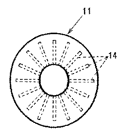
また、本発明に係るナトリウム−硫黄電池の正極構造では、インサイドアウト構造を採用して固体電解質管が使用される場合、上記導電体に形成される上記孔は固体電解質管の周囲に放射状に複数形成させることが望ましく、このような場合には、孔内での拡散が良くなるとともに、円筒状の固体電解質壁から同一距離の陽極用導電体内の活物質反応が均一化され電流密度のばらつきが少なくなる。このため、活物質の利用率と充放電効率が更に向上する。
更に、繊維状導電体に孔を施すということは繊維をカット或いは削除することになるので、孔を施さない場合に比べて固体電解質板側の導電材の密度は低くなる。これは、固体電解質板側の導電材中の電子導電性を低下させることになり、充電時の固体電解質板側の反応を緩和する作用を有し、結果として内部抵抗の低減を可能にするものである。
【0015】
上記導電体にあってはまた、最終的に断面がドーナツ形状の中空体で形成され、所定の幅厚みを有する。上記導電体は一体成形しなくても良く、断面が略扇形状の導電材部材を組み合わせて形成することもできる。この場合、固体電解質壁が当接する断面が略扇形状の導電材の内壁側から上記孔を容易に形成することができる。また、略扇形状の導電材を成形するにあったても、フラットな板状に形成した導電材に、長尺方向、及び/又は幅方向に切れ込み等の溝条部をカッター等で形成し、その板状の導電材を折り曲げて、孔が形成された断面が略扇形状の柱状体とし、これを組み合わせて中空体の導電体を形成しても良い。
尚、このような上記導電体は、カーボン化処理したフェルトとすると、加工上容易に達成することができる。
【0016】
【発明の実施の形態】
以下、本発明に係るナトリウム−硫黄電池の正極構造の好ましい実施の形態を詳述する。尚、本発明に係るナトリウム−硫黄電池の正極構造は以下の実施形態及び実施例に限るものではない。
図1は、本発明に係るナトリウム−硫黄電池の正極構造の縦断面図である。図2は、図1のナトリウム−硫黄電池に使用される導電体の組み立て斜視図である。図3は、図2に示す導電体に形成される孔の断面を示すための導電部材の拡大断面図である。図4は、組み立て後における導電体の孔の位置が示された図2に示す導電体の上面図である。図5は、本発明に係るナトリウム−硫黄電池の正極構造の導電体を図2に示す導電体と異なる工程で製造するための導電部材の斜視図である。図6は、組み立て後における導電体の孔の位置が示された図5からの導電体の上面図である。
【0017】
図1に示すように本実施の形態に係るナトリウム−硫黄電池の正極構造1は、ナトリウムイオンを選択的に透過させる筒状の固体電解質壁からなる固体電解質管2が中心に立設してある。固体電解質管2内には、負極活物質4を収容した負極管5が設けられている。負極管5の上部開口にはフランジ6が形成され、フランジ6上面には天面に陰極端子8を備えた陰極蓋7が液密に装着されて上記開口が封しされている。尚、負極管5の最底部に負極活物質4が移動できるように孔が形成されている。
フランジ6下面には絶縁リング9が固着され、絶縁リング9の下面にはリング状の蓋10が取り付けられ、蓋10は固体電解質管2の外側に配される導電体11の上面に設けられる。導電体11は、正極活物質が含浸されており、固体電解質管2と正極集電体として機能する円筒容器12との間に収容される。
【0018】
負極活物質4にはナトリウムが含まれ、導電体11に含浸される正極活物質には硫黄、多硫化ナトリウム等が挙げられる。固体電解質管2は有底の柱状管であり、その材質はナトリウムイオンに対して伝導性を有するセラミックスまたはガラス等からなるもの、例えばβ−アルミナ(Na2O・11Al2O3)や、安定化剤としてMgO、Li2O等が添加されたβ”−アルミナ(3Na2O・16Al2O3)等を好ましく用いることができる。正極集電体である円筒容器12の材質は例えばステンレス、Ni合金等が用いられる。
【0019】
本発明に係るナトリウム−硫黄電池の正極構造における導電体11は、炭素繊維からなり、炭素繊維は、PAN系炭素繊維、PVA系炭素繊維、PVC系炭素繊維、石油ピッチ系炭素繊維、石炭ピッチ系炭素繊維若しくは気相合成系炭素繊維のいずれのものであっても良く、また、黒鉛系炭素繊維であっても良い。特に、黒鉛系繊維を用いた場合には、ナトリウム−硫黄電池の内部抵抗を著しく低減することが可能となる。
【0020】
これらは、原料繊維を500乃至1500℃、好ましくは1000℃前後で焼成することにより、カーボン化処理して所望の導電部材、或いは導電体そのものに成形される。
従って、導電体11は、マット状、断面が扇状の柱尺状物、或いは中空体に上記繊維を焼成或いはカーボン化処理して形成された導電材を、そのまま、或いは組み合わせてナトリウム−硫黄電池1に使用される。導電体11は、そして所定幅の厚みを持たせて、上記固体電解質管2の周囲に配される。尚、導電体11の厚みは1mm乃至40mmの範囲に形成することが望ましい。所定幅を確保しないと、電池としてエネルギー量が十分に得られないおそれがある。
【0021】
本実施態様におけるナトリウム−硫黄電池1の導電体11にあっては、中空体を一旦、4分割して図2に示すように断面が扇形状の柱状物からなる導電部材13を再び組み合わせて形成される。また、図3に示すように、導電部材13を組み合わせる前に、固体電解質管2が当接する導電部材13の内壁面から複数の孔14が形成される。複数の孔14の全ては、導電体11を電池1内で立設したときに、内壁面から厚み方向の外壁面に向けて上向きに傾斜して設けられる。孔14の傾斜は水平方向に対して上向きであれば良く、例えば、水平方向に対して5°以上、特に10乃至80°の範囲であることが望ましい。
孔14の傾斜角度が5°未満では、ナトリウムリッチで硫黄プアーな多硫化ナトリウムが孔14を介して移動しないおそれがあり、傾斜角度が80°を超えれば、孔14の形成が難しくなる。
【0022】
上述のナトリウム−硫黄電池1は、例えば次のように製造される。まず、図2乃至図4に示すように、導電材21を組み合わせた導電体11は、断面が略ドーナツ状の中空体として構成され、固体電解質管2の周囲に放射状に孔14が形成される。次に、得られた導電体11を正極集電体である円筒容器12に挿入し、更に導電体11の中空部に固体電解質管2を挿入し、蓋10、絶縁リング9を取り付け、保護管3を挿入し、更に負極管5を挿入する。負極活物質2であるナトリウムを充填し、更に、電極蓋7で負極活物質4を密封することにより、ナトリウム−硫黄電池1を製造する。
【0023】
このように構成されるナトリウム−硫黄電池の正極構造1の負極における放電反応は、負極活物質4であるナトリウム(Na)がナトリウムイオン(Na+)と電子(e−)とに分かれ、ナトリウムイオン(Na+)は固体電解質2内を透過して正極活物質中の導電体11に侵入する。電子(e−)は負極集電体である陰極端子7を介して外部回路に流れる。正極における放電反応において、正極活物質3中に侵入したナトリウムイオン(Na+)が硫黄(S)と反応して、多硫化ナトリウム(Na2Sx)を生成する。
【0024】
一方、ナトリウム−硫黄電池の正極構造1の充電時には、放電反応と逆の反応が起こり、ナトリウム(Na)および硫黄(S)が生成する。通常は、多硫化ナトリウム(N2Sx)の一部が残留する程度まで充電する。硫黄(S)よりも多硫化ナトリウム(Na2Sx)の固有抵抗が低いために、多硫化ナトリウム(Na2Sx)を残存させておけば正極活物質の抵抗の上昇を抑えることが可能となる。
【0025】
充電時における多硫化ナトリウム(Na2Sx)は硫黄リッチな状態の多硫化ナトリウムとなり、特に、導電体11の固体電解質管2の近傍で硫黄リッチな多硫化ナトリウムが多くなり、導電体11の円筒容器12の近傍では未だナトリウムリッチな、或いは硫黄成分がプアーな多硫化ナトリウムが多く存在している。
下記表1に示すごとく、通常、ナトリウム−硫黄電池の充電時、即ち温度300乃至350℃に多硫化ナトリウムの導電率(抵抗値の逆数)は、硫黄成分がリッチな多硫化ナトリウムほど小さい。例えば、温度340℃における硫黄成分のリッチな多硫化ナトリウム(Na2S5.1)は、硫黄成分のプアーな多硫化ナトリウム(Na2S3.0)に比べて、1/2強であり、これは極めて高い抵抗値を示し、導電体11の内側に存在する状態が多くなる。このため、固体電解質管2の近傍の硫黄成分リッチな多硫化ナトリウムが更に生成すれば、内部抵抗の増加を招く。
【0026】
【表1】
【0027】
しかしながら、下記表2に示すようにナトリウムリッチな多硫化ナトリウムに対して、硫黄リッチな多硫化ナトリウムは密度が小さいため、また、下記表3に示すように表面張力も極めて低下するため、本発明に係るナトリウム−硫黄電池の正極構造にあっては、導電体11の複数の孔14を介して、ナトリウムリッチな多硫化ナトリウムが密度の低下した硫黄リッチな多硫化ナトリウムに換わり固体電解質管2側に移行してくる。このため、密度差対流による多硫化ナトリウムの変換が厚み方向に延びる孔14内で起こり易くなっている。
【0028】
【表2】
【0029】
【表3】
【0030】
従って、ナトリウム−硫黄電池1では、傾斜孔14内において比重差により、比重の大きいナトリウムリッチな多硫化ナトリウムが固体電解質管2側に移行しやすくなり、固体電解質管2側で電気抵抗の高い(又は導電率の低い)硫黄リッチな多硫化ナトリウムの濃度が高くなることなく、反応が連続的に起きるため、充電末期においても内部抵抗が増加することなく、活物質利用率を広く確保でき、充放電効率も高くなる。結果として高エネルギー密度の電池としての機能を十分に満たすことができる。
【0031】
図5は、本発明に係るナトリウム−硫黄電池の正極構造の導電体における上記導電体11を別の工程から製造するための導電部材の斜視図である。導電部材21はマット状或いは平坦な厚みのあるカーボンフェルトとして形成される。導電部材21は長尺方向に沿って片面に複数の切れ込み22が形成され、かかる切れ込み22は導電体21を湾曲させるために形成されるものであり、平坦な導電材21を断面が略扇状となる図2で示した導電部材13と略同様な形状に加工できるようにしている。
また導電材21には、幅方向に所定間隔をおいて切れ込み23が形成され、かかる切れ込み23は切れ込み22と異なり、導電材21面に垂直に切れ込まれるのではなく、垂直位置から少し傾斜させて切れ込まれる。
【0032】
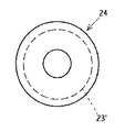
このような導電部材21を切れ込み22を内側にして折り曲げ、これらの導電材21を組み合わせて、図2に示したと同様な中空体を形成して導電体24とする。かかる導電体24は、図6に示すように切れ込み23が半径方向の全域に形成される孔23’として機能し、かかる孔23’も上向き傾斜している。
このため、このように形成される導電体24も上述した導電体13と同様な機能をするため、かかる導電体24をナトリウム−硫黄電池に利用しても、上述したと同様な作用効果を奏するものである。
【0033】
上記ナトリウム−硫黄電池1あっては、固体電解質管を用いたインサイドアウト構造を採用して、固体電解質管2の内側に負極活物質4であるナトリウムを収納し、固体電解質管2の外側に導電体11と正極活物質3である硫黄成分を配置しているが、これに限られず、正極活物質及び導電助材を固体電解質管に収納したものであっても良い。更に、ナトリウム−硫黄電池の構造はインサイドアウト構造に限るものではなく、例えば、電解漕の内部に平板状の固体電解質を配置し、この固体電解質を介して正極活物質と負極活物質とが対向して配置された構造であっても良い。また、ナトリウム−硫黄電池の正極構造の形態は円筒形に限られず、角形やその他の形状であっても良い。
【0034】
【発明の効果】
以上、説明したように本発明に係るナトリウム−硫黄電池によれば、立設された所定の厚み幅を有する導電体には、固体電解質壁と接する側から厚み幅方向に向けて孔が形成され、該孔は上記固体電解質壁から離れるに従って上向きに傾斜させて形成されているので、正極自体の抵抗を抑制し、充電に際して正極における導電体の内部抵抗を抑え、充放電効率を高く維持して、エネルギー密度も高めることができる。
【図面の簡単な説明】
【図1】図1は、本発明に係るナトリウム−硫黄電池の正極構造の縦断面図である。
【図2】図2は、図1のナトリウム−硫黄電池の正極構造に使用される導電体の組み立て斜視図である。
【図3】図3は、図2に示す導電体に形成される孔の断面を示すための導電部材の拡大断面図である。
【図4】図4は、組み立て後における導電体の孔の位置が示された図2に示す導電体の上面図である。
【図5】図5は、本発明に係るナトリウム−硫黄電池の正極構造の導電体を図2に示す導電体と異なる工程で製造するための導電部材の斜視図である。
【図6】図6は、組み立て後における導電体の孔の位置が示された図5からの導電体の上面図である。
【符号の説明】
1 ナトリウム−硫黄電池の正極構造
2 固体電解質管
4 負極活物質
8 負極端子
11 導電体
12 円筒容器(正極集電体)
13 導電部材
14 孔
21 導電部材
23 切れ込み
23’ 孔
24 導電体[0001]
TECHNICAL FIELD OF THE INVENTION
The present invention relates to a positive electrode structure of a sodium-sulfur battery, and more particularly, to a positive electrode structure of a sodium-sulfur battery used as a secondary battery for power storage, an emergency power supply, an uninterruptible power supply, and the like. is there.
[0002]
[Prior art]
2. Description of the Related Art Recently, sodium-sulfur batteries having a high active material utilization rate and a high charge / discharge efficiency have been actively developed for the purpose of leveling power during the day and night or at night, and for emergency or uninterrupted power use. Generally, in a sodium-sulfur battery, a negative electrode active material is accommodated in a solid electrolyte tube formed in a cylindrical shape (tube or deep cup), and an anode active material is arranged outside the negative electrode active material. The negative electrode active material contains sodium, and the solid electrolyte tube is made of β-alumina or the like that allows sodium ions and the like to pass through. Sulfur is used as the anode active material, and the sulfur is impregnated in the conductive anode conductor having conductivity and is dispersed and accommodated therein. When a solid electrolyte tube is used, the anode conductor is formed into a hollow body having a substantially donut-shaped cross section or is combined with a plurality of parts, and the conductor is made of graphite fiber, carbon fiber, or the like.
[0003]
In the positive electrode structure of a sodium-sulfur battery, during discharge, sodium and sulfur react to generate sodium polysulfide in the positive electrode chamber, and when charging, sodium and sulfur are reversibly generated from sodium polysulfide in the positive electrode chamber, or Rich sodium polysulfide increases.
That is, sodium (Na), which is the negative electrode active material, is divided into sodium ions (Na +) and electrons (e−), and the sodium ions (Na +) penetrate into the positive electrode active material through the solid electrolyte wall, and the electrons ( e-) flows from an anode current collector or the like to an external circuit. In the discharge reaction in the positive electrode, sodium ions (Na +) invading the positive electrode active material react with sulfur (S) to generate sodium polysulfide (Na 2 S x ).
During charging of a sodium-sulfur battery, a reaction opposite to the discharge reaction occurs, and sodium (Na) and sulfur (S) are generated. Usually, the battery is charged to the extent that a portion of sodium polysulfide (Na 2 S x ) remains. This is because the specific resistance of sodium polysulfide (Na 2 S x ) is lower than that of sulfur (S). Therefore, if sodium polysulfide (Na 2 S x ) is left, an increase in resistance of the positive electrode active material is suppressed. Because you can do it.
[0004]
By the way, during charging, sodium ions generated in a conductor having a predetermined thickness move to the solid electrolyte wall side, so that a reaction easily occurs in the conductor near the solid electrolyte wall, and as a result, sulfur near the solid electrolyte wall is generated. It becomes easy to become rich. Sulfur-rich sodium polysulfide reduces conductivity, causing an increase in internal resistance, preventing the movement of sodium ions generated in the outer conductor further, resulting in a decrease in charge / discharge efficiency. .
[0005]
Therefore, improvement of the conductor has been proposed to prevent such a decrease in the charge / discharge rate. For example, a conductor or the like was used in which the carbon fiber woven fabric was laminated and formed by performing needle punching, and the fiber diameter of the carbon fiber woven fabric was configured to be gradually reduced from the solid electrolyte wall toward the outside. A sodium-sulfur battery has been proposed (for example, see Patent Document 1). In addition, a carbon fiber woven fabric as a conductor is composed of a plurality of woven fabrics having different thicknesses, and a thick woven fabric is incorporated on the outside, and further, in a thickness direction of the plurality of carbon fiber woven fabrics. There is also proposed a fiber in which the ratio of oriented fibers is set to be higher toward the outside.
[0006]
Further, there has been proposed a material in which a substance layer having excellent sulfur resistance and sodium polysulfide and having low electron conductivity is adhered and arranged between a solid electrolyte and an electronic conductor (for example, see Patent Document 2).
In a sodium-sulfur battery using these conventional conductors, the production of the conductor is complicated, does not suppress an increase in the resistance of the positive electrode itself, and does not improve the charge / discharge efficiency. In addition, since the active material utilization is limited, the energy density cannot be increased.
[0007]
[Patent Document 1]
JP-A-8-31451 (Claim 1 of the claims)
[Patent Document 2]
JP-A-9-35741 (page 1)
[0008]
[Problems to be solved by the invention]
The present invention has been made in order to solve the above-mentioned problems, and suppresses the resistance of the positive electrode itself, suppresses the internal resistance of the conductor in the positive electrode during charging, maintains the charge / discharge efficiency high, and also increases the energy density. It is an object of the present invention to provide a positive electrode structure of a sodium-sulfur battery.
[0009]
[Means for Solving the Problems]
The inventor of the present invention focused on sodium polysulfide at a temperature of 300 ° C. to 350 ° C., and noticed that the density was different between the case where the sulfur content was high and the case where the sulfur content was low. At the same time, it was found that sodium polysulfide present near the outside of the sodium-rich, sulfur-poor conductor can move to the inside of the conductor, that is, to the solid electrolyte wall side by utilizing the specific gravity difference. It has been reached.
[0010]
That is, the positive electrode structure of the sodium-sulfur battery according to the present invention has the following configuration or means, and solves the above problem.
The positive electrode structure of the sodium-sulfur battery according to the present invention has, as a minimum premise, that a solid electrolyte wall that transmits sodium ions is provided upright, and that a predetermined thickness width provided along the solid electrolyte wall is provided. It is made of a positive electrode active material obtained by impregnating a conductor with sulfur.
[0011]
The positive electrode structure of the sodium-sulfur battery according to the present invention employs, for example, a structure (inside-out structure) in which a negative electrode active material and a positive electrode active material are separated by a cylindrical solid electrolyte wall that selectively transmits sodium. be able to. Sodium as a negative electrode active material is housed inside the solid electrolyte tube or the like, and a conductor and a sulfur component as a positive electrode active material may be arranged outside the solid electrolyte tube. The structure may be such that the conductor is housed in a solid electrolyte tube, and the negative electrode active material is disposed outside the tube. Further, the structure of the sodium-sulfur battery is not limited to the inside-out structure, and for example, a flat solid electrolyte wall is disposed inside the electrolysis tank, and a positive electrode active material and a negative electrode active material are interposed through the solid electrolyte wall. May be arranged to face each other. Further, the form of the positive electrode structure of the sodium-sulfur battery is not limited to a cylindrical shape, but may be a square shape or another shape.
[0012]
In the positive electrode structure of the sodium-sulfur battery according to the present invention, a hole is formed in the conductor in the thickness direction from the solid electrolyte wall side, and the hole is formed to be inclined upward as the distance from the solid electrolyte wall increases. It is characterized by having.
Here, the hole means a hole that penetrates the conductor from the inside to the outside or a hole that does not penetrate, and upward refers to a hole from the inside of the conductor on the side in contact with the solid electrolyte wall side to be erected from the inside to the outside. Is formed to be inclined upward, and the angle is at least equal to or greater than the horizontal direction, preferably 5 ° or more, and particularly preferably in the range of 10 ° to 80 °.
Also, the thickness width of the conductor is desirably at least 1 mm, and the thickness width of the conductor is usually at most 40 mm or less.
In addition, the process of forming the holes can be performed both in the case of using only the conductive material for the anode and in the case of after the sulfur impregnation, and an appropriate manufacturing process can be designed.
[0013]
At the end of charging, especially in the last stage, insulating sulfur or low-conductivity sodium polysulfide precipitates in the vicinity of the solid electrolyte wall, thereby increasing the internal resistance, which may decrease the active material utilization rate and the charge / discharge efficiency. There is. However, in the positive electrode structure of the sodium-sulfur battery according to the present invention, in the hole formed in the conductor, sodium polysulfide having a large sodium ratio and a large specific gravity migrates from the specific gravity difference to the solid electrolyte wall side along the inclined hole. Then, the sulfur-rich sodium polysulfide formed on the solid electrolyte wall side causes a specific gravity difference convection with the sodium polysulfide having a large specific gravity, and the polysulfide having a low conductivity (high electric resistance) and a small sodium ratio on the solid electrolyte wall side. The reaction can be carried out continuously without increasing the concentration of sodium or sulfur. For this reason, even in the last stage of charging, the active material utilization can be secured widely without increasing the internal resistance, and the charging / discharging efficiency also increases. As a result, a battery with a high energy density is possible.
[0014]
Further, in the positive electrode structure of the sodium-sulfur battery according to the present invention, when a solid electrolyte tube is used by adopting an inside-out structure, the plurality of holes formed in the conductor are radially formed around the solid electrolyte tube. In such a case, the diffusion in the pores is improved, and the active material reaction within the anode conductor at the same distance from the cylindrical solid electrolyte wall is uniformized, so that the current density varies. Less. For this reason, the utilization rate and charge / discharge efficiency of the active material are further improved.
Further, providing holes in the fibrous conductor means cutting or deleting the fibers, so that the density of the conductive material on the solid electrolyte plate side is lower than in the case where holes are not provided. This reduces the electronic conductivity of the conductive material on the solid electrolyte plate side, has the effect of relaxing the reaction on the solid electrolyte plate side during charging, and as a result, enables the internal resistance to be reduced. It is.
[0015]
The conductor is finally formed of a hollow body having a donut shape in cross section, and has a predetermined width and thickness. The conductor does not need to be integrally formed, and may be formed by combining conductive members having a substantially fan-shaped cross section. In this case, the hole can be easily formed from the inner wall side of the conductive material having a substantially fan-shaped cross section in contact with the solid electrolyte wall. Further, even when a substantially fan-shaped conductive material is formed, a groove or the like such as a cut in a longitudinal direction and / or a width direction is formed on a conductive material formed in a flat plate shape with a cutter or the like. Alternatively, the plate-shaped conductive material may be bent to form a columnar body having a substantially fan-shaped cross section in which holes are formed, and these may be combined to form a hollow conductive body.
It is to be noted that such a conductor can be easily achieved in terms of processing by using carbonized felt.
[0016]
BEST MODE FOR CARRYING OUT THE INVENTION
Hereinafter, preferred embodiments of the positive electrode structure of the sodium-sulfur battery according to the present invention will be described in detail. The positive electrode structure of the sodium-sulfur battery according to the present invention is not limited to the following embodiments and examples.
FIG. 1 is a longitudinal sectional view of a positive electrode structure of a sodium-sulfur battery according to the present invention. FIG. 2 is an assembled perspective view of a conductor used in the sodium-sulfur battery of FIG. FIG. 3 is an enlarged cross-sectional view of a conductive member for illustrating a cross section of a hole formed in the conductor illustrated in FIG. FIG. 4 is a top view of the conductor shown in FIG. 2 showing positions of holes of the conductor after assembly. FIG. 5 is a perspective view of a conductive member for manufacturing a conductor having a positive electrode structure of a sodium-sulfur battery according to the present invention by a different process from the conductor shown in FIG. FIG. 6 is a top view of the conductor from FIG. 5 showing the locations of the holes in the conductor after assembly.
[0017]
As shown in FIG. 1, the positive electrode structure 1 of the sodium-sulfur battery according to the present embodiment has a solid electrolyte tube 2 made of a cylindrical solid electrolyte wall that selectively allows sodium ions to penetrate, and stands upright at the center. . A negative electrode tube 5 containing a negative electrode active material 4 is provided in the solid electrolyte tube 2. A flange 6 is formed in an upper opening of the negative electrode tube 5, and a cathode lid 7 having a cathode terminal 8 on a top surface is liquid-tightly mounted on the upper surface of the flange 6, and the opening is sealed. A hole is formed at the bottom of the negative electrode tube 5 so that the negative electrode active material 4 can move.
An insulating ring 9 is fixed to a lower surface of the flange 6, and a ring-shaped lid 10 is attached to a lower surface of the insulating ring 9. The lid 10 is provided on an upper surface of a conductor 11 arranged outside the solid electrolyte tube 2. The conductor 11 is impregnated with a positive electrode active material, and is accommodated between the solid electrolyte tube 2 and a cylindrical container 12 functioning as a positive electrode current collector.
[0018]
The negative electrode active material 4 contains sodium, and the positive electrode active material impregnated in the conductor 11 includes sulfur, sodium polysulfide and the like. The solid electrolyte tube 2 is a bottomed columnar tube made of ceramics or glass having conductivity to sodium ions, such as β-alumina (Na 2 O · 11Al 2 O 3 ) or a stable material. As the agent, β ″ -alumina (3Na 2 O · 16Al 2 O 3 ) to which MgO, Li 2 O or the like is added can be preferably used. The material of the cylindrical container 12 serving as the positive electrode current collector is, for example, stainless steel, Ni alloy or the like is used.
[0019]
The conductor 11 in the positive electrode structure of the sodium-sulfur battery according to the present invention is made of carbon fiber, and the carbon fiber is PAN-based carbon fiber, PVA-based carbon fiber, PVC-based carbon fiber, petroleum pitch-based carbon fiber, or coal pitch-based. Any of carbon fibers or vapor-phase synthetic carbon fibers may be used, and graphite carbon fibers may be used. In particular, when graphite fibers are used, the internal resistance of the sodium-sulfur battery can be significantly reduced.
[0020]
These are fired at 500 to 1500 ° C., preferably around 1000 ° C., and carbonized to form a desired conductive member or a conductor itself.
Accordingly, the conductor 11 is a columnar material having a fan-shaped cross section, or a conductive material formed by baking or carbonizing the above-described fiber in a hollow body. Used for The conductor 11 is arranged around the solid electrolyte tube 2 with a predetermined width. Note that the thickness of the conductor 11 is desirably formed in the range of 1 mm to 40 mm. If the predetermined width is not ensured, a sufficient amount of energy may not be obtained as a battery.
[0021]
In the conductor 11 of the sodium-sulfur battery 1 according to the present embodiment, the hollow body is once divided into four parts, and the conductive member 13 formed of a columnar member having a fan-shaped cross section as shown in FIG. Is done. Further, as shown in FIG. 3, before combining the conductive members 13, a plurality of holes 14 are formed from the inner wall surface of the conductive member 13 with which the solid electrolyte tube 2 contacts. All of the plurality of holes 14 are provided to be inclined upward from the inner wall surface to the outer wall surface in the thickness direction when the conductor 11 is erected in the battery 1. It is sufficient that the inclination of the hole 14 is upward with respect to the horizontal direction. For example, it is desirable that the inclination is 5 ° or more, particularly 10 to 80 ° with respect to the horizontal direction.
If the inclination angle of the hole 14 is less than 5 °, sodium-rich, sulfur-poor sodium polysulfide may not move through the hole 14, and if the inclination angle exceeds 80 °, formation of the hole 14 becomes difficult.
[0022]
The above-mentioned sodium-sulfur battery 1 is manufactured, for example, as follows. First, as shown in FIGS. 2 to 4, the conductor 11 combined with the conductive material 21 is configured as a hollow body having a substantially donut-shaped cross section, and holes 14 are formed radially around the solid electrolyte tube 2. . Next, the obtained conductor 11 is inserted into a cylindrical container 12 which is a positive electrode current collector, the solid electrolyte tube 2 is further inserted into the hollow portion of the conductor 11, a cover 10 and an insulating ring 9 are attached, and a protective tube is provided. 3 and the negative electrode tube 5 are further inserted. The sodium-sulfur battery 1 is manufactured by filling the negative electrode active material 2 with sodium and sealing the negative electrode active material 4 with the electrode lid 7.
[0023]
In the discharge reaction at the negative electrode of the positive electrode structure 1 of the sodium-sulfur battery configured as described above, sodium (Na), which is the negative electrode active material 4, is divided into sodium ions (Na +) and electrons (e-). Na +) penetrates through the solid electrolyte 2 and penetrates into the conductor 11 in the positive electrode active material. The electrons (e−) flow to an external circuit via a cathode terminal 7 which is a negative electrode current collector. In the discharge reaction at the positive electrode, sodium ions (Na +) penetrating into the positive electrode active material 3 react with sulfur (S) to generate sodium polysulfide (Na 2 S x ).
[0024]
On the other hand, when charging the positive electrode structure 1 of the sodium-sulfur battery, a reaction opposite to the discharge reaction occurs, and sodium (Na) and sulfur (S) are generated. Normally, the battery is charged to the extent that a portion of sodium polysulfide (N 2 S x ) remains. Since the specific resistance of sodium polysulfide (Na 2 S x ) is lower than that of sulfur (S), an increase in the resistance of the positive electrode active material can be suppressed by leaving sodium polysulfide (Na 2 S x ). It becomes.
[0025]
Sodium polysulfide (Na 2 S x ) at the time of charging becomes sulfur-rich sodium polysulfide, and in particular, the amount of sulfur-rich sodium polysulfide near the solid electrolyte tube 2 of the conductor 11 increases. In the vicinity of the cylindrical container 12, there is still a large amount of sodium polysulfide rich in sodium or poor in the sulfur component.
As shown in Table 1 below, the conductivity (reciprocal of the resistance value) of sodium polysulfide is usually smaller when the sodium-sulfur battery is charged, that is, at a temperature of 300 to 350 ° C., as the sulfur component is richer. For example, at a temperature of 340 ° C., sodium polysulfide rich in sulfur component (Na 2 S 5.1 ) is slightly more than half in comparison with sodium polysulfide poor in sulfur component (Na 2 S 3.0 ). This shows an extremely high resistance value, and the state existing inside the conductor 11 increases. For this reason, if sodium polysulfide rich in the sulfur component near the solid electrolyte tube 2 is further generated, the internal resistance increases.
[0026]
[Table 1]
[0027]
However, the sulfur-rich sodium polysulfide has a lower density than the sodium-rich sodium polysulfide as shown in Table 2 below, and also has a very low surface tension as shown in Table 3 below. In the positive electrode structure of the sodium-sulfur battery according to the above, the sodium-rich sodium polysulfide is replaced with the sulfur-rich sodium polysulfide having a reduced density through the plurality of holes 14 of the conductor 11, and the solid electrolyte tube 2 side The transition to. For this reason, conversion of sodium polysulfide by density difference convection tends to occur in the hole 14 extending in the thickness direction.
[0028]
[Table 2]
[0029]
[Table 3]
[0030]
Therefore, in the sodium-sulfur battery 1, the specific gravity difference in the inclined hole 14 makes it easier for sodium-rich sodium polysulfide having a large specific gravity to move to the solid electrolyte tube 2 side, and the electric resistance is high on the solid electrolyte tube 2 side ( Since the reaction occurs continuously without increasing the concentration of sulfur-rich sodium polysulfide (or with low conductivity), the active material utilization can be secured widely without increasing the internal resistance even at the end of charging. The discharge efficiency also increases. As a result, the function as a battery having a high energy density can be sufficiently satisfied.
[0031]
FIG. 5 is a perspective view of a conductive member for manufacturing the conductor 11 from another step in the conductor having the positive electrode structure of the sodium-sulfur battery according to the present invention. The conductive member 21 is formed as a mat-like or flat-thick carbon felt. A plurality of cuts 22 are formed on one surface of the conductive member 21 along the longitudinal direction, and the cuts 22 are formed for bending the conductor 21. The flat conductive material 21 has a substantially fan-shaped cross section. The conductive member 13 shown in FIG. 2 can be processed into a substantially similar shape.
Cuts 23 are formed in the conductive material 21 at predetermined intervals in the width direction. Unlike the cuts 22, the cuts 23 are not cut perpendicularly to the surface of the conductive material 21, but are slightly inclined from the vertical position. Be cut off.
[0032]
Such a conductive member 21 is bent with the cut 22 inside, and these conductive members 21 are combined to form a hollow body similar to that shown in FIG. As shown in FIG. 6, the conductor 24 functions as a hole 23 'in which the cut 23 is formed in the entire radial direction, and the hole 23' is also inclined upward.
For this reason, since the conductor 24 formed in this way also has the same function as the conductor 13 described above, even if such a conductor 24 is used for a sodium-sulfur battery, the same operation and effect as described above are exerted. Things.
[0033]
The sodium-sulfur battery 1 employs an inside-out structure using a solid electrolyte tube, stores sodium, which is a negative electrode active material 4, inside a solid electrolyte tube 2, and conducts electricity outside the solid electrolyte tube 2. Although the body 11 and the sulfur component as the positive electrode active material 3 are arranged, the present invention is not limited to this, and the positive electrode active material and the conductive auxiliary material may be stored in a solid electrolyte tube. Further, the structure of the sodium-sulfur battery is not limited to the inside-out structure. For example, a plate-shaped solid electrolyte is disposed inside an electrolysis tank, and the positive electrode active material and the negative electrode active material face each other via this solid electrolyte. It may be a structure that is arranged in a manner. Further, the form of the positive electrode structure of the sodium-sulfur battery is not limited to a cylindrical shape, but may be a square shape or another shape.
[0034]
【The invention's effect】
As described above, according to the sodium-sulfur battery according to the present invention, the upright conductor having a predetermined thickness is formed with holes in the thickness width direction from the side in contact with the solid electrolyte wall. Since the holes are formed so as to be inclined upward with increasing distance from the solid electrolyte wall, the resistance of the positive electrode itself is suppressed, the internal resistance of the conductor in the positive electrode during charging is suppressed, and the charge / discharge efficiency is maintained high. Also, the energy density can be increased.
[Brief description of the drawings]
FIG. 1 is a longitudinal sectional view of a positive electrode structure of a sodium-sulfur battery according to the present invention.
FIG. 2 is an assembled perspective view of a conductor used in a positive electrode structure of the sodium-sulfur battery of FIG. 1;
FIG. 3 is an enlarged sectional view of a conductive member for illustrating a cross section of a hole formed in the conductor shown in FIG. 2;
FIG. 4 is a top view of the conductor shown in FIG. 2 showing positions of holes of the conductor after assembly.
FIG. 5 is a perspective view of a conductive member for manufacturing a conductor having a positive electrode structure of the sodium-sulfur battery according to the present invention in a step different from that of the conductor shown in FIG. 2;
FIG. 6 is a top view of the conductor from FIG. 5 showing the locations of the holes in the conductor after assembly.
[Explanation of symbols]
REFERENCE SIGNS LIST 1 positive electrode structure of sodium-sulfur battery 2 solid electrolyte tube 4 negative electrode active material 8 negative electrode terminal 11 conductor 12 cylindrical container (positive electrode current collector)
13 conductive member 14 hole 21 conductive member 23 cut 23 'hole 24 conductor