JP2004092964A - Heating cookware - Google Patents
Heating cookware Download PDFInfo
- Publication number
- JP2004092964A JP2004092964A JP2002252697A JP2002252697A JP2004092964A JP 2004092964 A JP2004092964 A JP 2004092964A JP 2002252697 A JP2002252697 A JP 2002252697A JP 2002252697 A JP2002252697 A JP 2002252697A JP 2004092964 A JP2004092964 A JP 2004092964A
- Authority
- JP
- Japan
- Prior art keywords
- heating cooker
- power supply
- frequency
- induction heating
- main
- Prior art date
- Legal status (The legal status is an assumption and is not a legal conclusion. Google has not performed a legal analysis and makes no representation as to the accuracy of the status listed.)
- Pending
Links
Images
Landscapes
- Control Of High-Frequency Heating Circuits (AREA)
- Induction Heating Cooking Devices (AREA)
- Electric Ovens (AREA)
Abstract
Description
【0001】
【発明の属する技術分野】
本発明は、加熱調理器に係り、さらに詳しくは、電力供給体を共用した誘導加熱調理器と高周波加熱調理器とからなる加熱調理器に関するものである。
【0002】
【従来の技術】
最近、流し台に組み込まれ、あるいは流し台等の上に載置された高電圧タイプ(200V)の誘導加熱調理器が脚光をあびており、普及率が急速に高まっている。これは高出力のため加熱調理時間が短かく高能率であり、また、ガス等を使用する調理器に比べて安全性が高いためであるといわれている。
一方、高周波加熱調理器は、あたため調理に優れており、広く家庭内に普及している。
しかしながら、電源コンセントや電圧(高周波加熱調理器は、100Vが主体)の関係で、前記両加熱調理器は、同じ台所の中でも離れて設置されており、不便であった。
【0003】
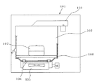
例えば、実公平7−33430号公報には、上記のような問題を解決するための複合調理器が記載されている。この複合調理器は、図11に示すように、底部に開口部を有し、上部にマグネトロン及び導破管からなる高周波加熱装置103が設けられ、本体101内に設置されて高周波加熱装置103により調理を行う調理室102を備え、この調理室102の開口部を遮断板104により開閉可能に構成し、遮断板104の下方に誘導加熱装置105を設けたものである。
【0004】
そして、高周波加熱装置103により調理を行う場合は、遮断板104により開口部を閉鎖し、トレイ106上に調理器具107を載置し、高周波加熱装置103に通電して被調理物を調理する。また、誘導加熱装置105により調理する場合は、遮断板104を移動させて調理室102の開口部を開放し、トレイ106上に調理器具107を載置して誘導加熱装置105に通電し、被調理物を調理する。
このように、1つの調理室102で高周波加熱装置103による調理と、誘導加熱装置105による調理とを共用するようにしたものである(従来技術1)。
【0005】
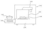
また、図12に示す複合調理器は、高周波加熱装置103の調理室102の下部に空間部108を設け、この空間部108に引出し可能に誘導加熱装置105を収容したもので、高周波加熱装置103により調理を行う場合は、誘導加熱装置105を空間部108に収容したままの状態で、調理室102内の被調理物109を加熱し、調理する。また、誘導加熱装置105により調理する場合は、図に示すように誘導加熱装置105を引き出して、本体101の外で調理するようにしたものである(従来技術2)。
【0006】
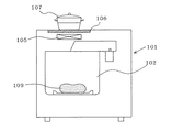
さらに、図13に示す複合調理器は、高周波加熱装置103の上方において本体101の上面にトレイ106を設け、その下方において本体101内に誘導加熱装置105を設置したもので、高周波加熱装置103で調理を行う場合は、調理室102内の被調理物109を加熱、調理し、誘導加熱装置105で調理する場合は、トレイ106上に調理器具107を載置して調理するようにしたものである(従来技術3)。
【0007】
【発明が解決しようとする課題】
図11の従来技術1においては、誘導加熱装置105で調理する場合、調理器具107を調理室102内に収容しなければならないので、大きな鍋やフライパンなどで調理しようとすると、取っ手が邪魔になって調理室102内に入りにくく、調理できないことがある。また、調理器具107が狭い調理室102に収容されているため、加熱中の被調理物の点検などがやりにくい。
【0008】
さらに、このような場合、通常誘導加熱装置105の誘導コイルは1個であり、複数の調理器具を同時に加熱することができない。若し、複数の誘導コイルを設けようとすると本体101が大きくなり、高周波加熱装置103の出力も大幅にアップしなければならない。
さらに、高周波加熱装置103による調理と、誘導加熱装置105により調理を同時に行うことができないなど、使い勝手の悪い調理器である。
【0009】
図12の従来技術2においては、誘導加熱装置105を調理室102の下方に収容するようにしているため、本体101が高くなり、また、誘導加熱装置105の出し入れのために電気的接続が複雑になり、故障の原因になりやすい。さらに、誘導加熱装置105を使用したのち本体101内に収容すると、高温のため冷却しにくい等の問題がある。
【0010】
図13の従来技術3においては、調理器具107が本体101の上に載置されるため不安定であり、また、調理器具107が高所に位置するため、加熱中の被調理物の点検などがやりにくく、使い勝手が悪い。
【0011】
本発明は、上記の課題を解決するためになされたもので、誘導加熱調理器と高周波加熱調理器が近接して設置され、それぞれ独立して調理を行うことができ、その上高圧電源を共用することのできる使い勝手のよい加熱調理器を提供することを目的としたものである。
【0012】
【課題を解決するための手段】
(1) 本発明に係る加熱調理器は、発熱体、該発熱体等を制御する制御部、前記発熱体や制御部に電力を供給する主電力供給体を備えた本体ケースと、非磁性材からなり前記本体ケースの上面を覆うトッププレート及び該トッププレートを保持する枠体からなる天板組立体とによって構成され、流し台等に載置又は組み込まれる誘導加熱調理器と、加熱室、高周波加熱発生体、該高周波発生体等を制御する制御部及び前記高周波加熱発生や制御部に電力を供給する主電力供給体を備えた本体ケースかなる高周波加熱調理器とを有し、該高周波加熱調理器を前記誘導加熱調理器に近接して前記流し台等の上に載置し、前記誘導加熱調理器の主電力供給体と前記高周波加熱調理器の主電力供給体との間を電気的に着脱自在に接続したものである。
【0013】
(2) 上記(1)の加熱調理器において、誘導加熱調理器の主電力供給体に電力を供給する高圧電源のコンセントを、流し台又はその近傍に設けた。
(3) 上記(1)又は(2)の加熱調理器において、主電力供給体を、誘導加熱調理器及び高周波加熱調理器の天板組立体を含む本体ケースの外面側に設けた。
(4) 上記(1)〜(3)のいずれかの加熱調理器において、主電力供給体を防水カバーで保護した。
【0014】
(5) 上記(1)〜(4)のいずれかの加熱調理器において、誘導加熱調理器と高周波加熱調理器への電力供給はメインスイッチにより行い、該メインスイッチを前記誘導加熱調理器及び高周波加熱調理器のいずれか一方に設けた。
(6) 上記(1)〜(5)のいずれかの加熱調理器において、メインスイッチの下流側において、前記誘導加熱調理器及び高周波加熱調理器にそれぞれ電力供給用スイッチを設けた。
【0015】
(7) 上記(1)〜(6)のいずれかの加熱調理器において、誘導加熱調理器と高周波加熱調理器のいずれか一方に主電力供給体を取出す開口部を設け、他方に主電力供給体を取出すと共に前記開口部に着脱自在に嵌合する接続部を設けた。
【0016】
(8) 本発明に係る加熱調理器は、発熱体、該発熱体を制御する制御部、前記発熱体や制御部に電力を供給する主電力供給体を備えた本体ケースと、非磁性材からなり前記本体ケースの上面を覆うトッププレート及び該トッププレートを保持する枠体からなる天板組立体とによって構成され、流し台等に載置又は組み込まれる誘導加熱調理器と、加熱室、高周波加熱発生体、該高周波発生体等を制御する制御部及び前記高周波加熱発生や制御部に電力を供給する主電力供給体を備えた本体ケースからなる高周波加熱調理器とを有し、前記誘導加熱調理器及び高周波加熱調理器の両者又はいずれか一方の本体ケース又は天板組立体の外面に高圧電源に接続される高電圧用コンセントを設けたものである。
【0017】
(9) 上記(8)の加熱調理器において、高電圧用コンセントは、本体ケースや天板組立体に形成された凹部内に設けられ、該凹部はシール用蓋体で閉塞するようにした。
【0018】
【発明の実施の形態】
実施の形態1
図1は本発明の実施の形態1に係る加熱調理器の斜視図、図2は模式的に示した図1の縦断面図で、誘導加熱調理器を流し台に組み込んだ場合を示してある。両図において、1は流し台100に組み込まれた誘導加熱調理器、51は誘導加熱調理器1に近接して流し台100の天板101上に載置された高周波加熱調理器である。
【0019】
誘導加熱調理器1において、2は上面が開口され、開口部外周にフランジ部3が設けられた箱状の本体ケースで、内部には取っ手4aを有し出し入れ自在に設けられた魚等を焼くための引出し状のグリラー4,電源部5、後述の発熱体等を制御する制御部6、電気部品や発熱体等を冷却する冷却用送風機7等が設けられている。8は一端に主電力供給体である電源プラグ9を有し、他端が電源部5に接続されたケーブルで、電源プラグ9は流し台100に設けた高圧電源(200V)のコンセント103に接続される。なお、この電源プラグ9は高周波加熱調理器51に設けてもよく、あるいは両加熱調理器1,51にそれぞれ設けてもよい。10は本体ケース2の前面側においてグリラー4の横に設けられた操作部で、電力供給用の電源スイッチ11,出力調整ダイアル12等が設けられている。13は前面側に開口する排気口である。
【0020】
15天板組立体で、開口部17、開口部17の外周に設けられたフランジ部18からなる枠体16と、複数の通気孔20を有し、枠体16の開口部17に取付けられた上フレーム19と、セラミックプレートの如き非磁性材からなり、開口部17の上面を覆って枠体16上に載置され、接着剤等により取付けられたトッププレート21とからなり、上フレーム19とトッププレート21との間には、上面に電磁誘導コイルや電気抵抗コイルからなる発熱体23が配設されたコイル支持台22が設けられている。そして、このコイル支持台22は、発熱体23をできるだけトッププレート21上の調理器具に近づけて、効率よく調理できるように、図示しないばねにより上方に付勢され、発熱体23を常にトッププレート21の下面に当接させている。
【0021】
24はトッププレート21の上面に印刷により設けられた、調理器具の載置位置を示す載置表示部、25は発熱体23の出力表示部、26は枠体16の前部側に設けた温度・タイマー表示部である。27は枠体16の後部側に設けられ、外気を導入して電源部5、制御部6、発熱体23等の発熱部を、冷却用送風機7によって冷却するための外気導入口である。
28は外気導入口27の両側に開口し、一端が電源部5に接続され、他端が後述の高周波加熱調理器51の配線66と接続される配線29を取出すための配線取出し部、27aはこの配線取出し部28を閉塞するカバーである。
【0022】
高周波加熱調理器51において、52は前面側が開口された箱状の本体ケース,53は本体ケース51内に設置された加熱室(ターンテーブル等は省略してある)で、マグネトロン55と導破管56からなる高周波発生体54が設けられている。57は高周波発生体54等の制御部、58は冷却用送風機である。60はハンドル60aを有し、下部を軸にして下方に回動するドア、61は本体ケース52の前面側において、ドア60の横に設けられた操作部で、電力供給用の電源スイッチ62、出力調整ダイアル63、表示部64等が設けられている。
【0023】
65は本体ケース52の両側壁の下方(図には一方の側だけ示してある)に開口し、一端が制御部57に接続され、他端が誘導加熱装置1の配線29に接続される配線66を取出すための配線取出し部で、不使用時はカバー(図示せず)で閉塞されている。67は冷却用送風機58の近傍において、本体ケース52の側壁に設けられた吸気口、68は本体ケース52の天板(又は後壁)に設けられた排気口である。
【0024】
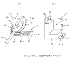
70は両者の配線29,66を接続したのち、両配線29,66及び両者の配線取出し部28,65を覆って閉塞する防水カバーで、図3(b)に示すように、L字状に形成されて下部及び側部が開口された本体部71と、ねじ挿通穴73を有し、本体部71の両端部に設けた上下の固定片72a,72bとからなっている。74は両者の前面側を結合するための前部接続具である。
【0025】
次に、本実施の形態に係る加熱調理器の流し台への設置手順について説明する。
先ず、図2に示すように、誘導加熱調理器1の本体ケース2を、流し台100の天板101に設けた開口部102から流し台100内に挿入し、そのフランジ部3をシールパッキン14を介して開口部102の周縁に係止させ、取付ける。ついで、本体ケース1上に天板組立体15を設置し、必要に応じて本体ケース2のフランジ部3又はフランジ部3と流し台100の天板101に、ねじ等により固定する。このとき、図3(a)に示すように、配線29を配線取出し部28から引き出しておく。
【0026】
次に、高周波加熱調理器51を、誘導加熱装置1の一方の側(図には左側の場合が示してある)において、流し台100の天板101上に、誘導加熱調理器1に近接又は当接させて載置する。このとき、図3(a)に示すように、配線66を配線取出し部65から引き出しておく。
【0027】
ついで、図3(a)に示す配線29と66を主電力供給体であるコネクタ29a,66aで接続し、配線引出し部28,65、配線29,66を含めてこれらの上を直接又はシールパッキンを介して防水カバー70で覆い、固定片72a,72bに設けたねじ挿通穴73に挿通したねじ75を、誘導加熱調理器1のフランジ16及び高周波加熱調理器51の側壁に設けたねじ穴28a,65aに螺入し、固定する。また、前面側に両者を跨いて前部接続具74を当接し、ねじで固定する。
【0028】
これにより、誘導加熱調理器1と高周波加熱調理器51の機械的、電気的の接続が終了する。そして、両者の配線取出し部28,65及び両者を電気的に接続する配線29,66及びコネクタ29a,66aは防水カバー70で覆われ、保護される。
【0029】
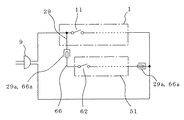
図4は本実施の形態の電気系の回路図である。本実施の形態においては、高圧電源のコンセント103に接続された主電力供給体である電源プラグ9を、誘導加熱調理器1に設けた電源スイッチ11に接続すると共に、この電源スイッチ11の入力側に接続された配線29を主電力供給体であるコネクタ29a,66a及び配線66を介して高周波加熱調理器51の電源スイッチ62に接続したものである。そして、電源スイッチ62をOFFの状態にし電源スイッチ11をONすれば誘導加熱調理器1に通電し、電源スイッチ11をOFFにして電源スイッチ62をONすれば高周波加熱調理器51に通電する。さらに、電源スイッチ11,62をONすれば、誘導加熱調理器1と高周波加熱調理器51の両者に通電するようにしたものである。
【0030】
図5は電気回路の他の例を示すもので、図4の電気回路において電源プラグ9と誘導加熱調理器1の電源スイッチ11との間に電力供給用のメインスイッチ11aを設けたものである。このメインスイッチ11aは誘導加熱調理器1に設けてもよく、あるいは高周波加熱調理器51やその他の場所(例えば、流し台100)に設けてもよい。
なお、上記の説明では、主電力供給体である電源プラグ9を誘導加熱調理器1に設けた場合を示したが、高周波加熱調理器51に設けてもよく、また、誘導加熱調理器1と高周波加熱調理器51で、共通に使用できる電気部品は両者で共通に使用すればよい。
【0031】
次に、上記のように構成した加熱調理器による調理の一例について説明する。誘導加熱調理器1で調理を行う場合は、被調理物が入れられた調理器具(以下、鍋という)をトッププレート21の載置表示部24上に載置し、電源スイッチ11をONする。このとき、高周波加熱調理器51の電源スイッチ62はOFFにする。なお、図5に示すように、メインスイッチ11aが設けられている場合は、先ずメインスイッチ11aをONし、ついで電源スイッチ11をONする。
【0032】
そして、操作部10に設けた出力調整ダイアル12により制御部6を介して発熱体23の出力(温度)を所望の値に設定すると共に、調理時間を設定する。このとき、温度・タイマー表示部26に当該発熱体23の設定温度及び調理時間が表示される。
【0033】
ついで、操作部10に設けたスタートボタン(図示せず)をONすると加熱体23に通電され、鍋を加熱して被調理物を調理する。調理中の鍋の温度は出力表示部25に表示される。この間冷却用送風機7が駆動されて、枠体16の後部に設けた外気導入口27から外気が吸引され、電源部5、制御部6、発熱体23等の発熱部品を冷却し、排気口13から排出される。調理が終ったときは、電源スイッチ11をOFFする。
【0034】
次に、高周波加熱調理器51で調理を行う場合は、加熱室53内のターンテーブル(図示せず)上に被調理物が入れられた鍋を載置する。そして、電源スチって62をONする(このとき誘導加熱調理器1の電源スイッチ11はOFF)。そして、出力調整ダイアル63により高周波発生体54の出力を所望の値に設定すると共に、調理時間を設定する。このとき、調理時間が表示部64に表示される。なお、メインスイッチ11aが設けられている場合は、先ずメインスイッチ11aをONし、ついて電源スイッチ62をONする。
【0035】
ついで、スタートボタン(図示せず)をONすると高周波発生体54が作動し、被調理物を加熱する。この間冷却用送風機58が駆動され、外気導入口67から吸引された外気により高周波発生体54,制御部57等が冷却され、排気口68から排出される。調理が終ったときは電源スイッチ62をOFFする。
また、調導加熱調理器1と高周波加熱調理器51を同時に使用する場合は、上記の操作を同時又は順次行えばよい。
【0036】
実施の形態2
図6は本発明の実施の形態2に係る加熱調理器の斜視図、図7は図6の模式的縦断面図、図8は図6の分離斜視図である。なお、実施の形態1と同じ部分にはこれと同じ符号を付し、説明を省略する。
本実施の形態は、誘導加熱調理器1と高周波加熱調理器51との接続部を覆う防水カバー80を誘導加熱調理器1の天板組立体15と一体に形成したものである。
【0037】
すなわち、誘導加熱調理器1の天板組立体15を構成する枠体16の高周波加熱調理器51と接続する側に、断面ほぼ台形状の防水カバー80を一体に形成し、その高周波加熱調理器51と接続する側の壁面に開口部81を設け、この開口部81の外周に接続部82を突設すると共に、上面にねじ挿通穴84を有するL字の固定片83を設けたものである。
また、高周波加熱調理器51の側壁の下部に、誘導加熱調理器1の防水カバー80の接続部82が嵌合する開口部69を設け、その上部に防水カバー80の固定片83に設けたねじ挿通穴84に対応してねじ穴69aを設けたものである。
【0038】
上記のように構成した本実施の形態においては、防水カバー80の接続部82から配線29を引出した状態で、誘導加熱調理器1を流し台100に組み込む。また、高周波加熱装置51の開口部69から配線66を引き出した状態で、流し台100の天板101上に誘導加熱調理器1からやや離れた位置に高周波加熱装置51を載置し、両者の配線29,66を主電力供給体であるコネクタ29a,66aで接続する。
【0039】
ついで、高周波加熱調理器51を誘導加熱調理器1に近付けて、その開口部69を防水カバー80の接続部82に嵌合する。そして、防水カバー80の固定片83のねじ挿通穴84に挿通したねじを、高周波加熱調理器51のねじ穴69aに螺入し、一体に固定する。このとき、配線29,66及びコネクタ29a,66aは防水カバー80内又は高周波加熱調理器51の本体ケース52内に位置する。
【0040】
上記のように構成した本実施の形態による被調理物の調理手順及び効果は、実施の形態1の場合と同様であるが、誘導加熱調理器1と高周波加熱調理器51の接続部の前後方向の全体を防水カバー80で覆うようにしたので、両者の間にごみや水等が侵入することがない。なお、防水カバー80は高周波加熱調理器51に設けてもよく、この場合は、開口部69は当然誘導加熱調理器1側に形成される。
【0041】
実施の形態3
図9は本発明の実施の形態3に係る加熱調理器の斜視図、図10は図9の要部の分解斜視図である。なお、実施の形態1と同じ部分にはこれと同じ符号を付し、説明を省略する。
本実施の形態は、誘導加熱調理器1と高周波加熱調理器51の両者を、流し台100の天板101上又はその他の器具上の設置したものである。
【0042】
また、本実施の形態は、天板組立体15の枠体16の後部側に設けた配線取出し口28の下面にパネル等を取付けて凹部85を形成し、この凹部85に主電源接続体である高電圧用のコンセント29bを設けて、このコンセント29bと電源部5との間を電源配線で接続すると共に、一端がプラグ31を介して、例えば家屋の壁面に設けた高圧電源のコンセント103aに着脱自在に接続されたケーブル30の他端を電源部5に接続したものである。また、必要に応じて、この凹部85に制御部6に接続されたコネクタ受部86を設けたものである。なお、このコネクタ受け部86は、誘導加熱調理器1又は高周波加熱調理器51に、両者に共用できる制御部を設けた場合に設置する。
【0043】
また、シール用蓋体70a(防水カバー)は、下面が開口され上面に開口部77を有し、取出し口28を閉塞しうる下部本体76と、ほぼL字状で開口部77を覆う大きさの開口部を有する底面と側面が開口された上部本体71aとを一体に形成したもので、下部本体76の両側に設けた固定片72bには、枠体16に設けたねじ穴28aに対応してねじ挿通穴73が設けられており、上部本体71aの上部に設けた固定片72aには、高周波加熱調理器51の側壁に設けたねじ穴(図示せず)に対応してねじ挿通穴73が設けられている。78はシールパッキンである。その他の構成は、実施の形態1の場合とほぼ同様であるが、天板組立体15の前面側が傾斜して見易くなっており、この傾斜部にメインスイッチ11aが設けられている。
【0044】
本実施の形態における電気回路も実施の形態1の図5に示す回路とほぼ同様であるが、誘導加熱調理器1又は高周波加熱調理器51の何れか一方に設けた制御部を他方が共用する場合は、両者をコネクタ受部86とコネクタ56bで接続した制御用配線で接続することになる。
【0045】
上記のように構成した本実施形態において、加熱調理器を例えば流し台100の天板101上に設置する場合は、先ず、誘導加熱調理器1を流し台100上に設置する。ついで、高周波加熱調理器51の側壁に設けた開口部(図3参照)から先端部にプラグ66aが接続された電源用の配線66を引き出し、また、必要に応じて、先端部にコネクタ56bが接続された制御用の配線56aも開口部から引出して、高周波加熱調理器51を誘導加熱調理器1に近接又は当接させて設置する。
【0046】
そして、電源用の配線66のプラグ66aを高電圧用のコンセント29bに接続し、必要に応じて制御用の配線56aのコネクタ56bをコネクタ受部86に接続する。
ついで、配線取出し口28及び配線66(56a)の上を覆うようにしてシールパッキン78を介して枠体16上にシール用蓋体70aを当接し、下部本体76に設けたねじ挿通穴73に挿通したねじを枠体16のねじ穴38aに螺入して固定すると共に、上部本体71aに設けたねじ挿通穴73に挿通したねじを、高周波加熱調理器51の側壁に設けたねじ穴に螺入して固定する。
これにより、誘導加熱調理器1と高周波加熱調理器51は機械的、電気的に一体に結合される。なお、凹部85、高電圧用のコンセント29b、コネクタ受け部86は、高周波加熱調理器51側に設けてもよい。
本実施の形態による被調理物の調理手段及び効果は、実施の形態1の場合とほぼ同様である。
【0047】
実施の形態4
本実施の形態は、誘導加熱調理器1及び高周波加熱調理器51の両者又はいずれか一方の本体ケース2,52又は天板組立体15の外面に、高圧電源に接続される高電圧用コンセント(図示せず)を設けたものである(図10参照)。これにより、流し台等の近傍で複数の高圧電気機器をその都度高電圧用コンセントを設けることなく、容易に利用できるので、誘導加熱調器や高周波加熱調理器等をさらに追加設置することができる。この場合、例えば誘導加熱調理器1の外面側に手動復帰型のブレーカーを設けておけば、さらに便利である。
【0048】
以上詳述したように、本発明は、誘導加熱調理器と高周波加熱調理器を流し台等に近接又は当接して設置したので、調理の際の利用者の移動が少なく便利である。
また、主電源供給体である電源プラグは上記いずれかの調理器に設けて共用できるので、高圧電源のコンセントは1個設ければよい。さらに、それぞれの調理器には高電圧用コンセントを設けたので、単独でも設置することができ、またあとから追加設置することもできる。
また、それぞれの調理器に主電力供給体である高電圧用プラグを設けることにより、製造時の評価試験も単体で行うことができる。さらに、電気部品の共用化が可能なので、小スペース化、小形化に貢献することができる。
【0049】
誘導加熱調理器と高周波加熱調理器は流し台等に併設されており、高周波加熱調理器は背が高いので、誘導加熱調理器上に載置された調理器具の移動や落下の防止壁として利用することができる。
また、主電力供給体を誘導加熱調理器及び高周波加熱調理器の天板組立体を含む本体ケースの外面側に設けたので、電気的接続の着脱を容易に行うことができ、これにより流し台等への設置やサービス時の両加熱調整器の分離を容易に行うことができる。また、誘導加熱調理器に主電力供給体である電源プラグを設けた場合は、高周波加熱調理器が故障しても誘導加熱調理器は使用することができる。
【0050】
誘導加熱調理器と高周波加熱調理器の接合部には水やほこりが入り易いが、防水カバーを設けることによりこれらの侵入を防止し、コネクタや配線を保護することができる。なお、防水パッキンを併用すれば、より効果的である。
また、誘導加熱調理器又は高周波加熱調理器のいずれか一方にメインスイッチを設けることにより、不使用時に両者の電源スイッチを操作する必要がなく、便利である。さらに、誘導加熱調理器及び高周波加熱調理器にそれぞれ電源スイッチを設けたので、使用しない調理器は電源をOFFすることができるので、便利かつ安全である。
【0051】
誘導加熱調理器と高周波加熱調理器を防水カバーにより着脱可能に一体化したので、両者を接続する配線が露出せずかつ防水することができる。また、なんらかの外力が加えられても調理器の移動を防止でき、さらに、分離が可能なため、サービスが容易である。
【0052】
【発明の効果】
本発明に係る加熱調理器は、誘導加熱調理器と高周波加熱調理器とを流し台等に近接して設置したので、それぞれ独立して調理を行うことができ、調理の際の移動も少なくてすみ、その上高圧電源を共用するようにしたので、使い勝手のよい加熱調理器を得ることができる。
【図面の簡単な説明】
【図1】本発明の実施の形態1に係る加熱調理器の斜視図である。
【図2】図1の縦断面図である。
【図3】図1の要部の斜視図である。
【図4】図1の電気系の回路図である。
【図5】図1の電気系の他の例の回路図である。
【図6】本発明の実施の形態2に係る加熱調理器の斜視図である。
【図7】図6の縦断面図である。
【図8】図6の分離斜視図である。
【図9】本発明の実施の形態3に係る加熱調理器の斜視図である。
【図10】図9の要部の分解斜視図である。
【図11】従来の複合調理器の一例の説明図である。
【図12】従来の複合調理器の他の例の説明図である。
【図13】従来の複合調理器のさらに他の例の説明図である。
【符号の説明】
1 誘導加熱調理器、2 本体ケース、5 電源部、6,57 制御部、7,58 冷却用送風機、9 主電力供給体(電源プラグ)、11,62 電源スイッチ、11a メインスイッチ、15 天板組立体、16 枠体、21 トッププレート、23 発熱体、28,65 配線の取出し部、29,66 配線、29a,66a 主電力供給体(コネクタ)、29b 高電圧用コンセント、51高周波加熱調理器、52 本体ケース、53 加熱室、54 高周波発生体、69 開口部、70,80 防水カバー、82 接続部、85 凹部、100 流し台、103,103a 高電圧源のコンセント。[0001]
TECHNICAL FIELD OF THE INVENTION
The present invention relates to a cooking device, and more particularly, to a cooking device including an induction cooking device and a high-frequency cooking device that share a power supply.
[0002]
[Prior art]
Recently, a high-voltage (200 V) induction heating cooker built in a sink or placed on a sink or the like has been spotlighted, and the penetration rate is rapidly increasing. It is said that this is because the heating and cooking time is short and the efficiency is high due to the high output, and the safety is higher than a cooking device using gas or the like.
On the other hand, a high-frequency heating cooker is excellent in warm cooking and is widely used in homes.
However, due to the power outlet and the voltage (high-frequency heating cookers are mainly 100 V), the two heating cookers are set apart in the same kitchen, which is inconvenient.
[0003]
For example, Japanese Utility Model Publication No. Hei 7-33430 describes a composite cooker for solving the above-mentioned problem. As shown in FIG. 11, the combined cooker has an opening at the bottom, and a high-
[0004]
When cooking is performed by the high-
As described above, cooking by the high-
[0005]
12 is provided with a
[0006]
Further, the composite cooker shown in FIG. 13 has a
[0007]
[Problems to be solved by the invention]
In the
[0008]
Furthermore, in such a case, the induction coil of the
Further, the cooking device is inconvenient because cooking by the high-
[0009]
In the
[0010]
In the
[0011]
The present invention has been made to solve the above-described problems, and an induction heating cooker and a high-frequency heating cooker are installed close to each other so that cooking can be performed independently of each other, and a high-voltage power supply is shared. It is an object of the present invention to provide a heating cooker which can be easily used.
[0012]
[Means for Solving the Problems]
(1) A heating cooker according to the present invention includes a main body case including a heating element, a control unit for controlling the heating element, a main power supply for supplying power to the heating element and the control unit, and a non-magnetic material. A top plate assembly comprising a top plate that covers the upper surface of the main body case and a frame that holds the top plate, and an induction heating cooker that is placed or incorporated in a sink or the like, a heating chamber, and high-frequency heating. A high-frequency heating cooker comprising a main body case including a generator, a control unit for controlling the high-frequency generator, and a main power supply for supplying power to the high-frequency heating generator and the control unit; A cooker is placed on the sink or the like in close proximity to the induction heating cooker, and the main power supply of the induction heating cooker and the main power supply of the high frequency heating cooker are electrically attached and detached. They are freely connected.
[0013]
(2) In the heating cooker of (1), an outlet of a high-voltage power supply for supplying power to a main power supply of the induction heating cooker is provided at or near the sink.
(3) In the heating cooker according to (1) or (2), the main power supply is provided on an outer surface side of a main body case including a top plate assembly of the induction heating cooker and the high frequency heating cooker.
(4) In the cooking device according to any one of (1) to (3), the main power supply is protected by a waterproof cover.
[0014]
(5) In the cooking device according to any one of (1) to (4), power is supplied to the induction cooking device and the high-frequency cooking device by a main switch, and the main switch is operated by the induction cooking device and the high-frequency cooking device. It was provided in one of the heating cookers.
(6) In the cooking device according to any one of (1) to (5), a power supply switch is provided in each of the induction cooking device and the high-frequency cooking device downstream of the main switch.
[0015]
(7) In the cooking device according to any one of the above (1) to (6), one of the induction heating cooking device and the high-frequency heating cooking device is provided with an opening for taking out a main power supply body, and the other is provided with a main power supply. A connection portion is provided for taking out the body and detachably fitting into the opening.
[0016]
(8) A heating cooker according to the present invention includes: a main body case including a heating element, a control unit for controlling the heating element, a main power supply for supplying power to the heating element and the control unit, and a non-magnetic material. A top plate covering the top surface of the main body case and a top plate assembly comprising a frame holding the top plate, and an induction heating cooker mounted or incorporated in a sink or the like; a heating chamber; A high-frequency heating cooker including a body, a control unit for controlling the high-frequency generator, and a main body case including a main power supply for supplying power to the high-frequency heating generation and control unit; A high-voltage outlet connected to a high-voltage power supply is provided on an outer surface of a main body case or a top plate assembly of both or one of the high-frequency heating cookers.
[0017]
(9) In the cooking device of the above (8), the high-voltage outlet is provided in a concave portion formed in the main body case or the top plate assembly, and the concave portion is closed by a sealing lid.
[0018]
BEST MODE FOR CARRYING OUT THE INVENTION
FIG. 1 is a perspective view of a heating cooker according to
[0019]
In the
[0020]
The fifteen-top assembly has a
[0021]
28 is an opening on both sides of the outside
[0022]
In the high
[0023]
A
[0024]
[0025]
Next, a procedure for installing the heating cooker according to the present embodiment on a sink will be described.
First, as shown in FIG. 2, the
[0026]
Next, the high-
[0027]
Then, the
[0028]
Thereby, the mechanical and electrical connection between the
[0029]
FIG. 4 is a circuit diagram of an electric system according to the present embodiment. In the present embodiment, a power plug 9 that is a main power supply connected to an
[0030]
FIG. 5 shows another example of the electric circuit, in which a
In the above description, the case where the power plug 9 as the main power supply is provided in the
[0031]
Next, an example of cooking by the heating cooker configured as described above will be described. When cooking is performed by the
[0032]
Then, the output (temperature) of the
[0033]
Next, when a start button (not shown) provided on the
[0034]
Next, when cooking is performed by the high-
[0035]
Then, when a start button (not shown) is turned on, the high-
When the
[0036]
6 is a perspective view of a heating cooker according to
In the present embodiment, a
[0037]
That is, a
In addition, an
[0038]
In the present embodiment configured as described above, the
[0039]
Next, the high-
[0040]
The cooking procedure and effect of the object to be cooked according to the present embodiment configured as described above are the same as those in the first embodiment, but the front-rear direction of the connection portion between the
[0041]
FIG. 9 is a perspective view of a heating cooker according to
In the present embodiment, both
[0042]
Further, in the present embodiment, a recess or the like is formed by attaching a panel or the like to the lower surface of the
[0043]
The sealing
[0044]
The electric circuit in the present embodiment is almost the same as the circuit shown in FIG. 5 of the first embodiment, but the control unit provided in either the
[0045]
In the present embodiment configured as described above, when the heating cooker is installed on the
[0046]
Then, the
Then, the sealing
Thereby, the
The cooking means and effects of the object to be cooked according to the present embodiment are almost the same as those in the first embodiment.
[0047]
In the present embodiment, a high-voltage outlet (which is connected to a high-voltage power supply) is provided on the outer surface of both or one of
[0048]
As described above in detail, according to the present invention, since the induction heating cooker and the high-frequency heating cooker are installed close to or in contact with a sink or the like, the movement of the user during cooking is small and convenient.
In addition, since the power plug serving as the main power supply is provided in any one of the above-mentioned cookers and can be shared, only one outlet for the high-voltage power supply may be provided. In addition, each cooker is provided with a high-voltage outlet, so that it can be installed alone or additionally.
Further, by providing a high-voltage plug as a main power supply to each cooker, an evaluation test at the time of manufacture can be performed alone. Further, since electric parts can be shared, it is possible to contribute to a reduction in space and size.
[0049]
An induction heating cooker and a high-frequency heating cooker are installed in a sink, etc., and the high-frequency heating cooker is taller, so it is used as a wall to prevent the movement of cooking utensils placed on the induction heating cooker or dropping be able to.
In addition, since the main power supply is provided on the outer surface side of the main body case including the top plate assembly of the induction heating cooker and the high frequency heating cooker, electrical connection and disconnection can be easily performed, thereby making it possible to use a sink or the like. The two heating regulators can be easily separated during installation and service. Further, when a power plug as a main power supply is provided in the induction heating cooker, the induction heating cooker can be used even if the high-frequency heating cooker fails.
[0050]
Water and dust easily enter the joint between the induction heating cooker and the high-frequency heating cooker. However, by providing a waterproof cover, intrusion thereof can be prevented, and the connector and wiring can be protected. The use of waterproof packing is more effective.
Further, by providing the main switch in either the induction heating cooker or the high frequency heating cooker, it is not necessary to operate both power switches when not in use, which is convenient. In addition, since the induction heating cooker and the high-frequency heating cooker are provided with power switches respectively, the cooking cookers that are not used can be turned off, which is convenient and safe.
[0051]
Since the induction heating cooker and the high-frequency heating cooker are detachably integrated by the waterproof cover, the wiring connecting them is not exposed and can be waterproofed. Further, even if some external force is applied, the movement of the cooker can be prevented, and furthermore, the cooker can be separated, so that the service is easy.
[0052]
【The invention's effect】
In the cooking device according to the present invention, the induction cooking device and the high-frequency cooking device are installed close to a sink or the like, so that cooking can be performed independently of each other, and movement during cooking can be reduced. In addition, since the high-voltage power supply is shared, an easy-to-use cooking device can be obtained.
[Brief description of the drawings]
FIG. 1 is a perspective view of a heating cooker according to
FIG. 2 is a longitudinal sectional view of FIG.
FIG. 3 is a perspective view of a main part of FIG. 1;
FIG. 4 is a circuit diagram of the electric system of FIG. 1;
FIG. 5 is a circuit diagram of another example of the electric system of FIG. 1;
FIG. 6 is a perspective view of a heating cooker according to
FIG. 7 is a longitudinal sectional view of FIG.
8 is an exploded perspective view of FIG.
FIG. 9 is a perspective view of a heating cooker according to
FIG. 10 is an exploded perspective view of a main part of FIG. 9;
FIG. 11 is an explanatory diagram of an example of a conventional composite cooking device.
FIG. 12 is an explanatory view of another example of the conventional composite cooking device.
FIG. 13 is an explanatory view of still another example of the conventional composite cooking device.
[Explanation of symbols]
1 induction heating cooker, 2 main body case, 5 power supply unit, 6,57 control unit, 7,58 cooling blower, 9 main power supply (power plug), 11, 62 power switch, 11a main switch, 15 top plate Assembly, 16 frames, 21 Top plate, 23 Heating element, 28, 65 Wiring take-out part, 29, 66 Wiring, 29a, 66a Main power supply (connector), 29b High voltage outlet, 51 High frequency heating cooker , 52 body case, 53 heating chamber, 54 high-frequency generator, 69 opening, 70, 80 waterproof cover, 82 connection, 85 recess, 100 sink, 103, 103a outlet for high voltage source.
Claims (9)
加熱室、高周波加熱発生体、該高周波発生体等を制御する制御部及び前記高周波加熱発生や制御部に電力を供給する主電力供給体を備えた本体ケースからなる高周波加熱調理器とを有し、
該高周波加熱調理器を前記誘導加熱調理器に近接して前記流し台等の上に載置し、前記誘導加熱調理器の主電力供給体と前記高周波加熱調理器の主電力供給体との間を電気的に着脱自在に接続したことを特徴とする誘導加熱調理器と高周波加熱調理器とからなる加熱調理器。A heating element, a control unit for controlling the heating element, a main body case including a main power supply for supplying power to the heating element and the control unit, a top plate made of non-magnetic material and covering an upper surface of the main body case; An induction heating cooker that is configured by a top plate assembly composed of a frame that holds the top plate, and is placed or incorporated in a sink or the like,
A high-frequency heating cooker including a heating chamber, a high-frequency heating generator, a control unit that controls the high-frequency generator and the like, and a main case that includes a main power supply that supplies power to the high-frequency heating generator and the control unit. ,
The high frequency heating cooker is placed on the sink or the like in close proximity to the induction heating cooker, and a space between the main power supply of the induction heating cooker and the main power supply of the high frequency heating cooker is provided. A heating cooker comprising an induction heating cooker and a high-frequency heating cooker electrically detachably connected.
加熱室、高周波加熱発生体、該高周波発生体等を制御する制御部及び前記高周波加熱発生や制御部に電力を供給する主電力供給体を備えた本体ケースからなる高周波加熱調理器とを有し、
前記誘導加熱調理器及び高周波加熱調理器の両者又はいずれか一方の本体ケース又は天板組立体の外面に高圧電源に接続される高電圧用コンセントを設けたことを特徴とする誘導加熱調理器と高周波加熱調理器からなる加熱調理器。A heating element, a control unit for controlling the heating element, a main body case including a main power supply for supplying power to the heating element and the control unit, a top plate made of non-magnetic material and covering an upper surface of the main body case; An induction heating cooker that is configured by a top plate assembly composed of a frame that holds the top plate, and is placed or incorporated in a sink or the like,
A high-frequency heating cooker including a heating chamber, a high-frequency heating generator, a control unit that controls the high-frequency generator and the like, and a main case that includes a main power supply that supplies power to the high-frequency heating generator and the control unit. ,
An induction heating cooker, wherein a high-voltage outlet connected to a high-voltage power supply is provided on an outer surface of the main body case or the top plate assembly of both or one of the induction heating cooker and the high-frequency heating cooker; A heating cooker consisting of a high-frequency cooker.
Priority Applications (1)
| Application Number | Priority Date | Filing Date | Title |
|---|---|---|---|
| JP2002252697A JP2004092964A (en) | 2002-08-30 | 2002-08-30 | Heating cookware |
Applications Claiming Priority (1)
| Application Number | Priority Date | Filing Date | Title |
|---|---|---|---|
| JP2002252697A JP2004092964A (en) | 2002-08-30 | 2002-08-30 | Heating cookware |
Publications (2)
| Publication Number | Publication Date |
|---|---|
| JP2004092964A true JP2004092964A (en) | 2004-03-25 |
| JP2004092964A5 JP2004092964A5 (en) | 2005-05-26 |
Family
ID=32058906
Family Applications (1)
| Application Number | Title | Priority Date | Filing Date |
|---|---|---|---|
| JP2002252697A Pending JP2004092964A (en) | 2002-08-30 | 2002-08-30 | Heating cookware |
Country Status (1)
| Country | Link |
|---|---|
| JP (1) | JP2004092964A (en) |
Cited By (1)
| Publication number | Priority date | Publication date | Assignee | Title |
|---|---|---|---|---|
| CN106352699A (en) * | 2016-11-15 | 2017-01-25 | 天津林立感应加热电炉制造有限公司 | Heating furnace with tandem control panel structure |
-
2002
- 2002-08-30 JP JP2002252697A patent/JP2004092964A/en active Pending
Cited By (1)
| Publication number | Priority date | Publication date | Assignee | Title |
|---|---|---|---|---|
| CN106352699A (en) * | 2016-11-15 | 2017-01-25 | 天津林立感应加热电炉制造有限公司 | Heating furnace with tandem control panel structure |
Similar Documents
| Publication | Publication Date | Title |
|---|---|---|
| US6362459B1 (en) | Electronically controlled roaster oven with digital control assembly | |
| EP3680556A1 (en) | Cooking appliance | |
| JP7055088B2 (en) | Cookware and kitchen furniture | |
| JP2004363005A (en) | Heating cooker | |
| KR20050071414A (en) | A heating appliance for cooking | |
| JP7494969B2 (en) | Combined heating cooker | |
| JP7380395B2 (en) | Induction heating cooker, built-in complex heating cooker, and kitchen furniture | |
| JP7450452B2 (en) | Operation management system for complex heating cookers, kitchen furniture, and home appliances | |
| JP2015207398A (en) | heating cooker | |
| JP2004092964A (en) | Heating cookware | |
| JP7400606B2 (en) | Inverter circuit board cooling structure and induction heating cooker | |
| KR100497907B1 (en) | Built-in type heating appliance for cooking | |
| JP2005011684A (en) | Heating cooker | |
| JP3757363B2 (en) | Cooker | |
| JP4430709B2 (en) | Cooker | |
| JP7550903B2 (en) | Built-in combination cooker and kitchen furniture | |
| JP7499904B2 (en) | Built-in combination cooker and kitchen furniture | |
| JP7352211B2 (en) | Built-in complex heating cooker and kitchen furniture | |
| JP7332006B2 (en) | Built-in compound type heating cooker and kitchen furniture | |
| JP7399048B2 (en) | heating cooker | |
| CN115517554A (en) | Combined multifunctional air frying and baking oven | |
| JP2023156503A (en) | heating cooker | |
| JP2004069073A (en) | Combination cooker | |
| JP2022105196A (en) | Composite type heating cooker and program for controlling the same | |
| JP2022051855A (en) | Built-in combined cooking equipment and kitchen furniture |
Legal Events
| Date | Code | Title | Description |
|---|---|---|---|
| A521 | Written amendment |
Free format text: JAPANESE INTERMEDIATE CODE: A523 Effective date: 20040722 |
|
| A621 | Written request for application examination |
Free format text: JAPANESE INTERMEDIATE CODE: A621 Effective date: 20040722 |
|
| A977 | Report on retrieval |
Free format text: JAPANESE INTERMEDIATE CODE: A971007 Effective date: 20050513 |
|
| A131 | Notification of reasons for refusal |
Free format text: JAPANESE INTERMEDIATE CODE: A131 Effective date: 20050816 |
|
| A02 | Decision of refusal |
Free format text: JAPANESE INTERMEDIATE CODE: A02 Effective date: 20060110 |


