JP2004088748A - High frequency glass antenna for automobile - Google Patents
High frequency glass antenna for automobile Download PDFInfo
- Publication number
- JP2004088748A JP2004088748A JP2003181065A JP2003181065A JP2004088748A JP 2004088748 A JP2004088748 A JP 2004088748A JP 2003181065 A JP2003181065 A JP 2003181065A JP 2003181065 A JP2003181065 A JP 2003181065A JP 2004088748 A JP2004088748 A JP 2004088748A
- Authority
- JP
- Japan
- Prior art keywords
- conductor
- loop
- main antenna
- glass plate
- ground
- Prior art date
- Legal status (The legal status is an assumption and is not a legal conclusion. Google has not performed a legal analysis and makes no representation as to the accuracy of the status listed.)
- Granted
Links
Images
Landscapes
- Fittings On The Vehicle Exterior For Carrying Loads, And Devices For Holding Or Mounting Articles (AREA)
- Details Of Aerials (AREA)
Abstract
【課題】充分な視野が確保され、FM放送帯の感度の平坦性が向上する。
【解決手段】給電点3aとアース点4aとは窓ガラス板1の周縁部近傍に配設され、主アンテナ導体3は給電点3aを起点として、窓ガラス板1の略中心が内側になるように反時計回り方向に伸長され、主アンテナ導体3の2箇所がループ構成導体5aにより接続され主アンテナ導体1とループ構成導体5aとでループ状導体を構成しており、アース導体4aが主アンテナ導体3及びループ構成導体5aと近接して容量結合される。
【選択図】図1A sufficient field of view is secured and the flatness of the sensitivity of the FM broadcast band is improved.
A feeding point 3a and a grounding point 4a are disposed in the vicinity of a peripheral portion of a window glass plate 1, and a main antenna conductor 3 starts from the feeding point 3a so that a substantially center of the window glass plate 1 is inside. The main antenna conductor 3 is connected to a loop constituent conductor 5a so that the main antenna conductor 1 and the loop constituent conductor 5a constitute a loop-shaped conductor, and the ground conductor 4a is the main antenna. Capacitively coupled in proximity to the conductor 3 and the loop constituent conductor 5a.
[Selection] Figure 1
Description
【0001】
【発明の属する技術分野】
本発明は、日本のFM放送帯(76〜90MHz)、米国のFM放送帯(88〜108MHz)の受信に適している自動車用高周波ガラスアンテナに関する。以下、日本のラジオFM放送帯及び米国のラジオFM放送帯を単にFM放送帯という。
【0002】
【従来の技術】
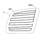
図2に示す放送受信用の自動車の後部サイド窓ガラス板1に設けられた自動車用高周波ガラスアンテナが従来より実施されている。図2において、後部サイド窓ガラス板1には、アンテナ導体23及び給電点23aが設けられている。アンテナ導体23は、導電性銀ペーストなどの導電性金属含有ペーストを後部サイド窓ガラス板1の車内側表面にプリントし、焼き付けて形成するなどの方法により製造される導体パターンであり、アンテナ導体23をアンテナとして利用する。
【0003】
この従来例では、アンテナ導体23が受信した信号は、給電点23aから同軸ケーブル(不図示)にてFM用の前置増幅器(不図示)まで伝送される。この前置増幅器は受信信号を増幅して、同軸ケーブルにて受信機(不図示)まで伝送している。アンテナ導体23はFM放送用アンテナのみならず、AM放送用アンテナとしても機能している。
【0004】
なお、受信の際、図2に示す自動車用高周波ガラスアンテナは、給電点の受信信号を受信機に送る単極アンテナとして機能する。図2に示す自動車用高周波ガラスアンテナでは、給電点と同軸ケーブルの内部導体を接続し、金属製の車体に同軸ケーブルの外部導体を接続する。
【0005】
図2に示す自動車用高周波ガラスアンテナでは、アンテナ導体23の導体長が充分でなく、FM放送帯の感度が悪い問題があった。さらに、後部サイド窓ガラス板1の略中心近傍にアンテナ導体23のパターンが配設されているため、視界が悪い問題があった。
【0006】
さらに、自動車の後部窓ガラス板にアンテナ導体とアース導体とを設けた双極アンテナも報告されているが(例えば、特許文献1参照)、アンテナ導体とアース導体との間の視野が悪い問題があった。
【0007】
【特許文献1】
特開平7−240614号公報
【0008】
【発明が解決しようとする課題】
本発明は、従来技術の有する前述の欠点を解消する自動車用高周波ガラスアンテナの提供を目的とする。
【0009】
【課題を解決するための手段】
本発明は、主アンテナ導体、アース導体、主アンテナ導体の給電点及びアース導体のアース点が自動車の窓ガラス板に設けられている自動車用高周波ガラスアンテナにおいて、
給電点とアース点とは窓ガラス板の周縁部近傍又は車体開口縁近傍に配設され、
車内側又は車外側から見て、
主アンテナ導体は給電点を起点として反時計回り方向に伸長されており、
主アンテナ導体の2箇所がループ構成導体により接続されて主アンテナ導体及びループ構成導体でループ状導体を構成しているか、又は、主アンテナ導体の1箇所及び給電点がループ構成導体により接続されて主アンテナ導体、ループ構成導体及び給電点でループ状導体を構成しているかしており、
アース導体の一部又は全部が主アンテナ導体、ループ構成導体及び給電点から選ばれる少なくとも一つと近接して容量結合されていることを特徴とする自動車用高周波ガラスアンテナを提供する。
【0010】
また、本発明は、主アンテナ導体、アース導体、主アンテナ導体の給電点及びアース導体のアース点が自動車の窓ガラス板に設けられている自動車用高周波ガラスアンテナにおいて、
給電点とアース点とは窓ガラス板の周縁部近傍又は車体開口縁近傍に配設され、
車内側又は車外側から見て、
主アンテナ導体は給電点を起点として反時計回り方向に伸長されており、
主アンテナ導体の2箇所が第1のループ構成導体により接続されて主アンテナ導体及び第1のループ構成導体でループ状導体を構成しているか、又は、主アンテナ導体の1箇所及び給電点が第1のループ構成導体により接続されて主アンテナ導体、第1のループ構成導体及び給電点で第1のループ状導体を構成しており、
第1のループ状導体に含まれない主アンテナ導体の2箇所が第2のループ構成導体により接続されて、主アンテナ導体と第2のループ構成導体とで第2のループ状導体を構成しており、
アース導体の一部又は全部が、主アンテナ導体、第1のループ構成導体、第2のループ構成導体及び給電点から選ばれる少なくとも一つと近接して容量結合されていることを特徴とする自動車用高周波ガラスアンテナを提供する。
【0011】
また、本発明は、主アンテナ導体、アース導体、主アンテナ導体の給電点及びアース導体のアース点が自動車の窓ガラス板に設けられている自動車用高周波ガラスアンテナにおいて、
給電点及びアース点は窓ガラス板の周縁部近傍又は車体開口縁近傍に配設され、
車内側又は車外側から見て、
主アンテナ導体は給電点を起点として窓ガラス板の周縁部又は車体開口縁にほぼ沿って反時計回り方向に、少なくとも窓ガラス板の下辺まで伸長されており、主アンテナ導体の2箇所がループ構成導体により接続されて主アンテナ導体及びループ構成導体でループ状導体を構成しているか、又は、主アンテナ導体の1箇所及び給電点がループ構成導体により接続されて主アンテナ導体、ループ構成導体及び給電点でループ状導体を構成しているかしており、
アース点を起点として伸長されているアース導体の一部又は全部が、主アンテナ導体の下辺及びループ構成導体から選ばれる少なくとも一つと近接して容量結合されていることを特徴とする自動車用高周波ガラスアンテナを提供する。
【0012】
また、本発明は、主アンテナ導体、アース導体、主アンテナ導体の給電点及びアース導体のアース点が自動車の窓ガラス板に設けられている自動車用高周波ガラスアンテナにおいて、
給電点及びアース点は窓ガラス板の周縁部近傍又は車体開口縁近傍に配設され、給電点は前記窓ガラス板の上下略中心より上方に配されており、
車内側又は車外側から見て、
主アンテナ導体は給電点を起点として窓ガラス板の周縁部又は車体開口縁にほぼ沿って反時計回り方向に、少なくとも窓ガラス板の下辺まで伸長されており、窓ガラス板の上下略中心より上方の主アンテナ導体の2箇所が第1のループ構成導体により接続されて主アンテナ導体及び第1のループ構成導体でループ状導体を構成しているか、又は、窓ガラス板の上下略中心より上方の主アンテナ導体の1箇所及び給電点が第1のループ構成導体により接続されて主アンテナ導体、第1のループ構成導体及び給電点で第1のループ状導体を構成しており、
第1のループ状導体に含まれない、かつ、窓ガラス板の上下略中心より、下方の主アンテナ導体の2箇所が第2のループ構成導体により接続されて、主アンテナ導体と第2のループ構成導体とで第2のループ状導体を構成しており、
アース点を起点として伸長されているアース導体の一部又は全部が、主アンテナ導体の下辺、第1のループ構成導体及び第2のループ構成導体から選ばれる少なくとも一つと近接して容量結合されていることを特徴とする自動車用高周波ガラスアンテナを提供する。
【0013】
【発明の実施の形態】
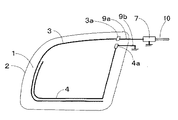
以下、本発明を図面に従って詳細に説明する。図1は本発明の自動車用高周波ガラスアンテナの一実施例の構成図である。図1及び後述する各図において、方向は図面上での方向をいうものとする。
【0014】
本発明の自動車用窓ガラスアンテナが設けられる窓ガラス板は、前部サイド窓ガラス板、後部窓ガラス板、前部窓ガラス板、ルーフ窓ガラス板等どのようなものであってもよいが、図1では窓ガラス板として後部サイド窓ガラス板を用いることとする。したがって、後述する説明中で後部サイド窓ガラス板を上記他の窓ガラス板で読み替えることができるものとする。
【0015】
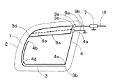
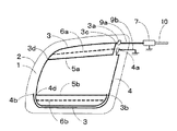
図1において、1は自動車の後部サイド窓ガラス板、2は車体開口縁、3は主アンテナ導体、3aは主アンテナ導体3の給電点、3bは主アンテナ導体3の先端部(開放端)、3cは主アンテナ導体3の第1の箇所、3dは主アンテナ導体3の第2の箇所、4はアース導体、4aはアース点、4bはアース導体4の先端部(開放端)、4cはアース導体4の曲折していう箇所、4dはアース導体4が曲がっている箇所、5aはループ構成導体、6aは補助ループ構成導体(点線)、7はアンテナ周辺回路、9aは給電点3a側のリード線、9bはアース点4a側のリード線、10は同軸ケーブルである。
【0016】
なお、以下の説明において、特記しない場合には、方向は図面上での方向をいうものとする。また、本発明において、通常、車体開口縁2は後部サイド窓ガラス板1の周縁部より若干小さい寸法(通常数cm)となり、後部サイド窓ガラス板1の周縁部に沿って形状が定められるため、主アンテナ導体3、給電点3a、アース導体4及びアース点4aの配置の以下の説明において、車体開口縁2を後部サイド窓ガラス板1の周縁部で読み替えることができるものとする。
【0017】
本発明では、主アンテナ導体3、アース導体4、給電点3a及びアース点4aが後部サイド窓ガラス板1に設けられている。給電点3aとアース点4aとは車体開口縁2近傍に配設されている。
【0018】
主アンテナ導体3は給電点3aを起点として、サイド窓ガラス板1の略中心が内側になるように反時計回り方向に伸長されている。図1に示す例では、主アンテナ導体3は給電点3aを起点として後部サイド窓ガラス板1の周縁部にほぼ沿って反時計回り方向に、車体開口縁2の下辺まで伸長され、その先端部3bは車体開口縁2の右下角近傍まで達している。しかし、これに限定されず、主アンテナ導体3が車体開口縁2の左辺まで伸長されていれば使用できる。
【0019】
図1に示す例では、主アンテナ導体3の第1の箇所3cと第2の箇所3dとの2箇所がループ構成導体5aにより接続されて主アンテナ導体3とループ構成導体5aとでループ状導体を構成している。しかし、これに限定されず、給電点3aと第2の箇所3dとの2箇所とがループ構成導体5aにより接続されて主アンテナ導体3、給電点3a及びループ構成導体5aとでループ状導体を構成してもよい。図1に示す例では、所望の受信周波数帯の中域及び高域の感度を向上させることができる。補助ループ構成導体6aは必要に応じて設けられ、主アンテナ導体3の箇所とループ構成導体5aの箇所とを結線している。補助ループ構成導体を設ける理由については、後述する。
【0020】
給電点3aと第2の箇所3dとの2箇所とがループ構成導体5aにより接続される場合には、主アンテナ導体3の任意箇所又はループ構成導体5aの任意箇所と、給電点3aとを補助ループ構成導体6aにより結線してもよい。
【0021】
本発明において、ループ状導体を備える理由は、通常、一つのガラスアンテナで所望の受信周波数帯の全域をカバーすることは困難であり、所望の受信周波数帯の中心付近の周波数の感度を上昇させようとすると、所望の受信周波数帯の低域及び高域の感度が下降する。
【0022】
本発明において、仮に主アンテナ導体3を半分に分割し、給電点3aに近い領域と、主アンテナ導体3の先端部3bに近い領域とに分けるとすると、給電点3aに近い領域に配設されているループ状導体は、所望の受信周波数帯の高域の感度向上に寄与する。主アンテナ導体3の先端部3bに近い領域に配設されているループ状導体は、所望の受信周波数帯の低域の感度向上に寄与する。
【0023】
本発明において、必要に応じて補助ループ構成導体が設けられる。補助ループ構成導体はループ状導体の2箇所を結び接続する。補助ループ構成導体が一つ設けられることにより、ループ状導体が2つに分割され、2つのループが構成される。補助ループ構成導体は、複数本設けられてもよい。補助ループ構成導体が複数本設けられる場合には、新たに設けられる補助ループ構成導体が、ループ状導体の2箇所、既に設けられている補助ループ構成導体の箇所とループ状導体の箇所又は補助ループ構成導体の2箇所を結び接続するものであってもよい。補助ループ状導体を備えることにより、所望の受信周波数帯の低域又は高域の感度が上昇する。
【0024】
本発明において、給電点3aが配設される後部サイド窓ガラス板1の好ましい箇所は、感度向上の観点から言えば、後部サイド窓ガラス板1の後方側の上側車体開口縁2近傍、後部サイド窓ガラス板1の前方側の上側車体開口縁2近傍、後部サイド窓ガラス板1の後方側の下側車体開口縁2近傍、後部サイド窓ガラス板1の前方側の下側車体開口縁2近傍、の順である。
【0025】
ただし、後部サイド窓ガラス板1の後方側の上側車体開口縁2近傍、又は、後部サイド窓ガラス板1の後方側の下側車体開口縁2近傍に給電点3aが設けられる場合には、同軸ケーブル10が長くなる欠点がある。
【0026】
図1に示す例では、アース点4aは給電点3aの略下方に配設されているが、これに限定されず、アース点4aが配設される後部サイド窓ガラス板1の箇所は給電点3aの略上方、略左方及び略右方から選ばれる少なくとも一つであってもよい。
【0027】
図1に示す例では、給電点3aとアース点4aとは、相互に近接しており、アース導体4の長さを確保するためにはこのようにすることが好ましいが、これに限定されず、給電点3aとアース点4aとが離れていても使用できる。
【0028】
給電点3aとアース点4aとが離れている例としては、図12に示す例が挙げられる。図12に示す例では、給電点3aが後部サイド窓ガラス板1の右上角近傍に設けられており、アース点4aは後部サイド窓ガラス板1の右下角近傍に設けられている。アース点4aから左方にアース導体4が伸長されている。
【0029】
図12に示す例のようにした場合には、左右の視野は向上する利点があるが、アース導体4の長さを確保することが困難となる。図1に示す例と、図12に示す例とを比較すると、アース導体4の長さを確保するために図12に示す先端部4bは、図1に示す先端部4bより上方に配設されていることがわかる。
【0030】
図1に示す例では、アース導体4はアース点4aを起点として車体開口縁2の右辺に沿って略下方に伸長された後、車体開口縁2の右下角近傍の曲折箇所4cにて曲折され、略左方に主アンテナ導体3の下辺に略沿って伸長され、箇所4dにて曲がって略上方に伸長され、その先端部4bは第2の箇所3d近傍まで達している。
【0031】
図1に示す例では、後部サイド窓ガラス板1の形状は略平行四辺形である。しかし、本発明では、これに限定されず、後部サイド窓ガラス板1の形状は、略台形、略菱形等の略四角形、略多角形、略三角形、略円形、略楕円形等であってもよい。
【0032】
図1に示す例では、アース導体4の一部(車体開口縁2の下辺近傍のアース導体4の一部及び車体開口縁2の左辺近傍のアース導体4の一部)は、車体開口縁2の下辺近傍及び車体開口縁2の左辺近傍の主アンテナ導体3の一部と近接して容量結合されている。しかし、これに限定されず、アース導体4の一部又は全部が車体開口縁2の上辺近傍の主アンテナ導体3の一部、車体開口縁2の左辺近傍の主アンテナ導体3の一部、車体開口縁2の下辺近傍の主アンテナ導体3の一部及びループ構成導体5aから選ばれる少なくとも一つと近接して容量結合されていれば使用できる。
【0033】
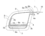
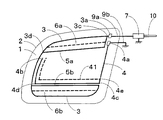
図3は図1に示す実施例とは別の実施例の構成図である。図1に示す例では、後部サイド窓ガラス板1の上下略中心より上方にループ構成導体5aが配設されている。これに対して、図3に示す例では、後部サイド窓ガラス板1の上下略中心より下方にループ構成導体5bが配設されている。
【0034】
図3に示す例では、主アンテナ導体3は、給電点3aを起点としてサイド窓ガラス板1の略中心が内側になるように反時計回り方向に伸長されて車体開口縁2の下辺まで伸長された後、車体開口縁2の右下角近傍にて略上方にやや伸長される。
【0035】
図3に示す例では、先端部3bと箇所3eとは、ループ構成導体5bにより接続される。ループ構成導体5bは車体開口縁2の下辺と略平行になっている。箇所3eは車体開口縁2の左下角近傍に配されている。
【0036】
図3に示す例では、アース点4aは給電点3aの略下方に配設されている。アース導体4はアース点4aを起点として車体開口縁2の右辺に沿って略下方に伸長された後、車体開口縁2の右下角近傍の箇所4cにて曲折して、略左方にループ構成導体5bに略沿って伸長され、箇所4dにて曲がって略上方に伸長され、その先端部4bは車体開口縁2の左上角近傍まで達している。
【0037】
図3に示す例では、アース導体4の一部(アース導体4の下辺及びアース導体4の左辺)は、ループ構成導体5b及び主アンテナ導体3の左辺と近接して容量結合されている。しかし、これに限定されず、アース導体4の一部又は全部が主アンテナ導体3の上辺、主アンテナ導体3の左辺、主アンテナ導体3の下辺、ループ構成導体5b及び給電点3aから選ばれる少なくとも一つと近接して容量結合されていれば使用できる。図3に示す例では、所望の受信周波数帯の低域及び中域の感度を向上させることができる。図3に示す例においても、必要に応じて補助ループ構成導体6bが設けられる。補助ループ構成導体6bはループ状導体の2箇所を結び接続する。
【0038】
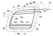
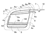
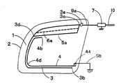
図4は図3に示す実施例とは別の実施例の構成図である。図4に示す例は、図3に示す例に図1に示すループ構成導体5aを追加した以外は図3に示す例と同様の仕様とした自動車用高周波ガラスアンテナである。図4に示す例では、所望の受信周波数帯の低域、中域及び高域の感度を向上でき、所望の受信周波数帯において、平坦な周波数−感度特性が得ることができる。
【0039】
図5は図4に示す実施例とは別の実施例の構成図である。図4に示す例では、アース導体4が主アンテナ導体3の内側に時計回り方向に伸長されている。これに対して、図5に示す例では、アース導体4が主アンテナ導体3の外側に時計回り方向に伸長されており、アース導体4は主に主アンテナ導体の下辺と容量結合している。
【0040】
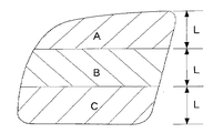
図6は、後部サイド窓ガラス板1を上下方向等間隔(L)に3分割し、上から順にA領域、B領域、C領域とする場合を表した平面図である。視野をできるだけ広くするために、図1、3に示す例において、ループ構成導体がB領域に配設されていないことが好ましい。同様に視野をできるだけ広くするために、図4、5及び後述する図7、8に示す例において、第1のループ構成導体及び第2のループ構成導体がB領域に配設されていないことが好ましい。
【0041】
図7、8は図4に示す実施例とは別の実施例の構成図である。図7、8に示す例は、図4に示す例のアース導体4に補助アース導体を付設したものである。図7に示す例において、補助アース導体41は箇所4c近傍上方のアース導体4の箇所4eを起点としてアース導体4の下辺に沿って左方に伸長され、箇所4d近傍で曲折して略上方に伸長され、補助アース導体41の先端部は第2の箇所3d近傍まで達している。
【0042】
図8に示す例において、補助アース導体42はアース導体4の箇所4eを起点としてアース導体4の下辺に沿って左方に伸長されて、補助アース導体42の先端部はアース導体4に接続されており、アース導体4の下辺と補助アース導体42とでループを構成している。補助アース導体41又は補助アース導体42とがアース導体4に付設されることにより、所望の受信周波数帯の全域の感度が向上する。
【0043】
本発明において、主アンテナ導体3の導体長(給電点3aを含まず)は、所望の受信周波数帯の中心周波数FMの波長をλM、所望の受信周波数帯の最低周波数FLの波長をλLとするとき、0.7・(1/4)・(λM+λL)×K〜1.2・(1/4)・(λM+λL)×Kとすることが好ましい。この範囲内である場合にはこの範囲外である場合と比較して所望の受信周波数帯の低域又は中域の感度が向上する。なお、Kはガラス短縮率であって、通常0.64である。日本のFM放送帯の中心周波数FMは、83.0MHzである。
【0044】
リード線9aの長さは100〜300mm、特には150〜250mmが好ましい。リード線9aの長さが100mm以上である場合には実装が容易となり、リード線9aの長さが300mm以下である場合にはS/N比が向上し、周波数−感度特性が安定する。
【0045】
本発明において、アース導体4の導体長は、0.8・(λM/3)×K〜1.2・(λM/3)×Kとすることが好ましい。この範囲内である場合にはこの範囲外である場合と比較して所望の放送帯の感度が向上する。リード線9bの長さは100〜300mm、特には150〜250mmが好ましい。リード線9bの長さが100mm以上である場合には実装が容易となり、リード線9bの長さが300mm以下である場合には、周波数−感度特性が安定する。
【0046】
図1におけるループ状導体の導体長及び図3における第1のループ状導体の導体長は、所望の受信周波数帯の最高周波数FHの波長をλHとするとき、0.6・((λM+λH)/4)×K〜1.2・((λM+λH)/4)×Kとすることが好ましい。この範囲内である場合にはこの範囲外である場合と比較して所望の放送帯の高域の感度が向上する。
【0047】
図2におけるループ状導体の導体長及び図3における第2のループ状導体の導体長は、0.5・((λM+λL)/4)×K〜((λM+λL)/4)×Kとすることが好ましい。この範囲内である場合にはこの範囲外である場合と比較して所望の受信周波数帯の低域の感度が向上する。
【0048】
図4、5、7、8に示す例において、第1のループ状導体と第2のループ状導体との間(箇所3dと箇所3eとの間)の主アンテナ導体3の導体長は、(1/4)・(λM/4)×K〜(1/2)・(λM/4)×Kとすることが好ましい。この範囲内である場合にはこの範囲外である場合と比較して所望の受信周波数帯の感度の平坦性が向上する。感度の平坦性とは、所望の受信周波数帯内で最高感度と最低感度との差をいう。
【0049】
本発明において、仮に容量結合部を短絡させたものと仮定して、給電点3aとアース点4aとを結線する導体の最大外周の導体長(例えば、図4に示す例では、先端部3bと箇所4cにて主アンテナ導体3とアース導体4とを短絡させたものと仮定した場合において、主アンテナ導体3の導体長と、アース点4aから箇所4cまでのアース導体4の導体長(アース点4aを含まず)と、容量結合部の間隔との和の長さ)は、0.8・(λM/2)×K〜1.4・(λM/2)×Kとすることが好ましい。この範囲内である場合にはこの範囲外である場合と比較して所望の放送帯の感度が向上する。
【0050】
本発明において、給電点3aとアース点4aとの間隔、主アンテナ導体3とアース点4aとの最短間隔、及び、ループ状導体とアース点4aとの最短間隔は、6.0mm以上、特には、10mm以上が好ましい。6.0mm以上である場合には6.0mm未満と比較して感度が向上する。
【0051】
本発明において、容量結合部の間隔、すなわち、例えば、図1、3、4、5、7、8における主アンテナ導体3の左辺とアース導体4の左辺との間隔、図3、4、6、7、8におけるアース導体4とループ構成導体5bとの間隔、及び、図5における主アンテナ導体3の下辺とアース導体4との間隔は、0.5〜8.0mm、特には0.5〜6.0mmが好ましい。後述する図11に示すとおり、この間隔が0.5mm以上であると、主アンテナ導体、アース導体及びループ構成導体が含む金属のマイグレーション等が起こりにくく、両者が短絡する危険性が少ない。この間隔が8.0mm以下では両者が効果的な容量結合となり易く、急激に感度が向上する。
【0052】
本発明において、主アンテナ導体、アース導体及びループ構成導体が方向を変えるとき、湾曲して方向を変えても又は曲折して方向を変えても、どちらでもよい。例えば、アース導体4が箇所4cで曲折して方向を変えているが、湾曲して方向を変えてもよい。
【0053】
また、パターンとして見る場合には、図1、3、4、5、7、8における自動車用高周波ガラスアンテナは、車内側から見ている。しかし、これに限定されず、図1、3、4、5、7、8における自動車用高周波ガラスアンテナのパターンが車外側から見るものであってもよい。
【0054】
本発明において、第1のループ状導体と第2のループ状導体とは別に主アンテナ導体に1つ以上のループ状導体を設けてもよい。また、図1、3、4、5、7、8における主アンテナ導体、給電点、アース導体、アース点、ループ構成導体及び補助ループ構成導体には補助導体は付設されていないが、これに限定されず、位相調整及び指向性調整のために、主アンテナ導体、給電点、アース導体、アース点、ループ構成導体及び補助ループ構成導体に、接続導体を介して又は介さずに、略T字状、略L字状、ループ状等の補助導体が付設されていてもよい。
【0055】
本発明において、所望の受信周波数帯としては、FM放送帯の他、短波放送帯(2.3〜26.1MHz)、テレビVHF帯(90〜108MHz、170〜222MHz)、テレビUHF帯(470〜770MHz)、北米及び欧州のテレビVHF帯(45〜86MHz、175〜225MHz)、自動車電話用の800MHz帯(810〜960MHz)、自動車電話用の1.5GHz帯(1.429〜1.501GHz)、UHF帯(300MHz〜3GHz)及びGPS(Global Positioning System、人工衛星のGPS信号1575.42MHz)、VICS(Vehicle Information and Communication System、ヴィークル インフォメーション アンド コミュニケーション システム)等が該当する。
【0056】
本発明の自動車用高周波ガラスアンテナは、所望の受信周波数帯の他に、短波放送帯、中波放送帯(520〜1700kHz)及び長波放送帯(150〜280kHz)から選ばれる少なくとも一つの周波数帯との兼用のアンテナとして利用できる。
【0057】
本発明において、アンテナ周辺回路7は、必要に応じて設けられる。アンテナ周辺回路7としては、インピーダンスマッチング回路、前置増幅回路、共振回路等が挙げられ、特に限定されない。
【0058】
本発明において、主アンテナ導体、給電点、アース導体、アース点、ループ構成導体及び補助ループ構成導体は、通常、銀ペースト等の、導電性金属を含有するペーストを後部サイド窓ガラス板の車内側表面にプリントし、焼付けて形成される。しかし、この形成方法に限定されず、銅等の導電性物質からなる、線状体又は箔状体を、後部サイド窓ガラス板の車内側表面又は車外側表面に形成してもよく、後部サイド窓ガラス板自身の内部に設けてもよい。
【0059】
【実施例】
以下、図面にしたがって、実施例を詳細に説明する。
【0060】
「例1(実施例)」
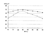
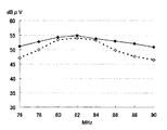
自動車の後部サイド窓ガラス板を使用し、図4に示すような自動車用高周波ガラスアンテナを製作した。補助ループ構成導体6a、6bは設けた。アンテナ周辺回路7は前置増幅器とした。この前置増幅器のFM放送帯での増幅度は、+5.0dBであった。各部の寸法、定数は以下のとおりである。また、後部窓ガラス板1は自動車の左側のものであり、車内側から見たパターンであって、図面右側が自動車前方である。前置増幅器の出力端での、FM放送帯の周波数−感度特性を図9に実線で示す。
【0061】
後部サイド窓ガラス板1の縦の最大値 380mm、
後部サイド窓ガラス板1の横の最大値 400mm、
車体開口縁2の縦の最大値 360mm、
車体開口縁2の横の最大値 380mm、
主アンテナ導体3の導体長(給電点3aを含まず) 1080mm、
主アンテナ導体3の第1の箇所3cと第2の箇所3dとの間の導体長425mm、
主アンテナ導体3の箇所3eと第2の箇所3dとの間の導体長 200mm、
主アンテナ導体3の箇所3eと先端部3bとの間の導体長 450mm、
アース導体4の導体長(アース点4aを含まず) 725mm、
アース点4aから箇所4cまでのアース導体4の導体長(アース点を含まず)215mm、
アース導体4の箇所4cから箇所4dまでの導体長 345mm、
アース導体4の箇所4dから先端部4bまでの導体長 150mm、
ループ構成導体5a 435mm
ループ構成導体5b 350mm。
【0062】
補助ループ構成導体6a 360mm、
補助ループ構成導体6b 345mm、
主アンテナ導体3の左辺とアース導体4の左辺との最短間隔 2.0mm、
アース導体4の下辺とループ構成導体5bとの最短間隔 2.0mm、
主アンテナ導体3の上辺と補助ループ構成導体6aとの最大間隔 35mm、
ループ構成導体5aと補助ループ構成導体6aとの最大間隔 35mm、
主アンテナ導体3の下辺と補助ループ構成導体6bとの最大間隔 35mm、
ループ構成導体5bと補助ループ構成導体6bとの最大間隔 35mm。
【0063】
リード線9aの長さ 250mm、
リード線9bの長さ 250mm、
給電点3aとアース点4aとの間隔 15mm、
アース点4aとループ構成導体5aの右辺との最短間隔 15mm、
給電点3aの縦×横(最大値)の寸法 30×15mm、
アース点4aの縦×横(最大値)の寸法 30×15mm、
アース導体4の下辺とループ構成導体5bとの間隔 2.0mm、
アース導体4の左辺と主アンテナ導体3の左辺との間隔 2.0mm。
【0064】
「例2(実施例)」
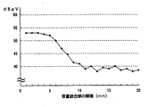
容量結合部の間隔(アース導体4の下辺とループ構成導体5bとの間隔、及び、アース導体4の左辺と主アンテナ導体の左辺との間隔)を変更した以外は、例1と同様の仕様とした自動車用高周波ガラスアンテナを製作した。容量結合部の間隔−日本のFM放送帯の平均感度特性を図11に示す。この結果により、容量結合部の間隔が、8.0mm以下では両者が効果的な容量結合となり、急激に感度が向上することがわかる。
【0065】
「例3(比較例)」
自動車の後部サイド窓ガラス板1を使用し、図10に示すような自動車用高周波ガラスアンテナを製作した。各部の寸法、定数は以下のとおりである。FM放送帯の周波数−感度特性を図9に点線で示す。なお、前置増幅器及び測定条件は例1と同様である。
【0066】
主アンテナ導体3の導体長(給電点3aを含まず) 1010mm、
アース導体4の導体長(アース点4aを含まず) 810mm、
主アンテナ導体3とアース導体4との最短間隔 2.0mm、
給電点3aとアース点4aとの間隔 15mm。
【0067】
「例4(実施例)」
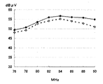
補助ループ構成導体6a、6bを設けない以外は、例1と同様の仕様の自動車用高周波ガラスアンテナを製作した。FM放送帯の周波数−感度特性を図13に破線で示す。なお、比較のために、図13に例1のFM放送帯の周波数−感度特性を実線で示した。
【0068】
「例5(実施例)」
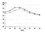
自動車の後部サイド窓ガラス板を使用し、図1に示すような自動車用高周波ガラスアンテナを製作した。各部の寸法、定数は例1と同様である。FM放送帯の周波数−感度特性を図14に示す。図14において、実線は補助ループ構成導体6aを設けた場合を示し、破線は補助ループ構成導体6aを設けなかった場合を示す。
【0069】
「例6(実施例)」
自動車の後部サイド窓ガラス板を使用し、図3に示すような自動車用高周波ガラスアンテナを製作した。各部の寸法、定数は例1と同様である。FM放送帯の周波数−感度特性を図15に示す。図1において、実線は補助ループ構成導体6bを設けた場合を示し、破線は補助ループ構成導体6bを設けなかった場合を示す。
【0070】
【発明の効果】
本発明では、主アンテナ導体にループ状導体が設けられており、主アンテナ導体とアース導体とが容量結合されているため、所望の受信周波数帯の中心付近の周波数の感度を上昇させようとした場合であっても、所望の受信周波数帯の低域及び高域の少なくとも一方の感度を向上できる。また、本発明において、第1のループ状導体と第2のループ状導体とを設けた場合には、所望の受信周波数帯の感度の平坦性が向上する。
【0071】
本発明の自動車用高周波ガラスアンテナをサイド窓ガラス板に設けた場合であって、ループ状導体、第1のループ状導体及び第2のループ状導体がB領域に配設されていない場合には、充分な視野が確保される。
【図面の簡単な説明】
【図1】本発明の自動車用高周波ガラスアンテナの一実施例の構成図。
【図2】従来例の構成図。
【図3】別の実施例の構成図。
【図4】別の実施例の構成図。
【図5】別の実施例の構成図。
【図6】後部サイド窓ガラス板1を上下方向等間隔(L)に3分割し、上から順にA領域、B領域、C領域とする場合を表した平面図。
【図7】別の実施例の構成図。
【図8】別の実施例の構成図。
【図9】例1、3のFM放送帯の周波数−感度特性図。
【図10】比較例であって、例3の自動車用高周波ガラスアンテナの構成図。
【図11】例2の容量結合部の間隔−日本のFM放送帯の平均感度特性図。
【図12】図1に示す例とは別の実施例であって、給電点3aとアース点4aとが離れている実施例の構成図。
【図13】例4のFM放送帯の周波数−感度特性図。
【図14】例5のFM放送帯の周波数−感度特性図。
【図15】例6のFM放送帯の周波数−感度特性図。
【符号の説明】
1:自動車の後部サイド窓ガラス板
2:車体開口縁
3:主アンテナ導体
3a:主アンテナ導体3の給電点
3b:主アンテナ導体3の開放端
3c:主アンテナ導体3の第1の箇所
3d:主アンテナ導体3の第2の箇所
4:アース導体
4a:アース点
4b:アース導体4の先端部
4c:アース導体4の曲折していう箇所
4d:アース導体4の湾曲又は曲折している箇所
5a:ループ構成導体
6a:補助ループ構成導体(点線)
7:アンテナ周辺回路
9a、9b:リード線
10:同軸ケーブル[0001]
BACKGROUND OF THE INVENTION
The present invention relates to a high frequency glass antenna for automobiles suitable for reception in the FM broadcast band of Japan (76 to 90 MHz) and the FM broadcast band of the United States (88 to 108 MHz). Hereinafter, the Japanese radio FM broadcast band and the US radio FM broadcast band are simply referred to as FM broadcast bands.
[0002]
[Prior art]
2. Description of the Related Art A high frequency glass antenna for automobiles provided on a rear side
[0003]
In this conventional example, a signal received by the
[0004]
In reception, the high-frequency glass antenna for automobiles shown in FIG. 2 functions as a single-pole antenna that sends a reception signal at a feeding point to a receiver. In the high-frequency glass antenna for an automobile shown in FIG. 2, the feeding point and the inner conductor of the coaxial cable are connected, and the outer conductor of the coaxial cable is connected to a metal vehicle body.
[0005]
In the high-frequency glass antenna for automobiles shown in FIG. 2, there is a problem that the conductor length of the
[0006]
Furthermore, although a bipolar antenna in which an antenna conductor and a ground conductor are provided on a rear window glass plate of an automobile has been reported (for example, see Patent Document 1), there is a problem that the field of view between the antenna conductor and the ground conductor is poor. It was.
[0007]
[Patent Document 1]
Japanese Patent Laid-Open No. 7-240614
[0008]
[Problems to be solved by the invention]
An object of the present invention is to provide a high-frequency glass antenna for an automobile that eliminates the above-mentioned drawbacks of the prior art.
[0009]
[Means for Solving the Problems]
The present invention relates to a high frequency glass antenna for an automobile in which a main antenna conductor, an earth conductor, a feeding point of the main antenna conductor and an earth point of the earth conductor are provided on a window glass plate of the automobile
The feeding point and the ground point are arranged in the vicinity of the peripheral portion of the window glass plate or in the vicinity of the vehicle body opening edge,
Seen from the inside or outside of the car,
The main antenna conductor is extended counterclockwise from the feed point,
Two locations of the main antenna conductor are connected by a loop constituent conductor and the main antenna conductor and the loop constituent conductor constitute a loop-shaped conductor, or one location of the main antenna conductor and a feeding point are connected by the loop constituent conductor. Whether the main antenna conductor, loop constituent conductor, and feed point constitute a loop conductor,
Provided is a high-frequency glass antenna for an automobile, wherein a part or all of a ground conductor is capacitively coupled in proximity to at least one selected from a main antenna conductor, a loop constituent conductor, and a feeding point.
[0010]
Further, the present invention relates to a high frequency glass antenna for an automobile in which a main antenna conductor, a ground conductor, a feeding point of the main antenna conductor and a ground point of the ground conductor are provided on a window glass plate of the automobile,
The feeding point and the grounding point are arranged near the periphery of the window glass plate or near the vehicle body opening edge,
Seen from the inside or outside of the car,
The main antenna conductor extends in the counterclockwise direction starting from the feed point,
Two locations of the main antenna conductor are connected by the first loop constituent conductor and the main antenna conductor and the first loop constituent conductor constitute a loop-shaped conductor, or one location of the main antenna conductor and the feeding point are the first Connected by one loop constituent conductor to form a first loop conductor by the main antenna conductor, the first loop constituent conductor and the feeding point,
Two portions of the main antenna conductor not included in the first loop conductor are connected by the second loop constituent conductor, and the main loop conductor and the second loop constituent conductor constitute the second loop conductor. And
A part or all of the ground conductor is capacitively coupled in proximity to at least one selected from a main antenna conductor, a first loop constituent conductor, a second loop constituent conductor, and a feeding point. A high frequency glass antenna is provided.
[0011]
Further, the present invention relates to a high frequency glass antenna for an automobile in which a main antenna conductor, a ground conductor, a feeding point of the main antenna conductor and a ground point of the ground conductor are provided on a window glass plate of the automobile,
The feeding point and the ground point are arranged near the periphery of the window glass plate or near the opening edge of the vehicle body,
Seen from the inside or outside of the car,
The main antenna conductor extends from the feeding point to the window glass plate in the counterclockwise direction almost along the peripheral edge of the window glass plate or the vehicle body opening edge to at least the lower side of the window glass plate, and the two main antenna conductors form a loop. The main antenna conductor and the loop constituting conductor are connected by a conductor to form a loop-shaped conductor, or one point of the main antenna conductor and the feeding point are connected by the loop constituting conductor to be connected to the main antenna conductor, the loop constituting conductor and the feeding Do you make a loop-shaped conductor with dots,
A high-frequency glass for automobiles, wherein a part or all of a ground conductor extending from a ground point is capacitively coupled in proximity to at least one selected from the lower side of the main antenna conductor and a loop constituent conductor Provide an antenna.
[0012]
Further, the present invention relates to a high frequency glass antenna for an automobile in which a main antenna conductor, a ground conductor, a feeding point of the main antenna conductor and a ground point of the ground conductor are provided on a window glass plate of the automobile,
The feeding point and the grounding point are disposed near the peripheral edge of the window glass plate or near the vehicle body opening edge, and the feeding point is arranged above the substantially vertical center of the window glass plate,
Seen from the inside or outside of the car,
The main antenna conductor extends from the feeding point to the window glass plate in the counterclockwise direction almost along the peripheral edge of the window glass plate or the vehicle body opening edge, and at least to the lower side of the window glass plate, and above the vertical center of the window glass plate. The two main antenna conductors are connected by a first loop constituent conductor to form a loop-shaped conductor with the main antenna conductor and the first loop constituent conductor, or above the vertical center of the window glass plate. One location of the main antenna conductor and the feeding point are connected by the first loop constituting conductor to constitute the main antenna conductor, the first loop constituting conductor and the feeding point to form the first loop-shaped conductor,
The main antenna conductor and the second loop are not included in the first loop-shaped conductor, and are connected to the main antenna conductor at two locations by the second loop constituent conductor from the substantially vertical center of the window glass plate. A second loop conductor is formed with the constituent conductor,
A part or all of the ground conductor extended from the ground point is capacitively coupled in proximity to at least one selected from the lower side of the main antenna conductor, the first loop constituent conductor, and the second loop constituent conductor. A high frequency glass antenna for automobiles is provided.
[0013]
DETAILED DESCRIPTION OF THE INVENTION
Hereinafter, the present invention will be described in detail with reference to the drawings. FIG. 1 is a block diagram of an embodiment of a high frequency glass antenna for automobiles according to the present invention. In FIG. 1 and each drawing described later, the direction refers to the direction on the drawing.
[0014]
The window glass plate on which the automobile window glass antenna of the present invention is provided may be any of a front side window glass plate, a rear window glass plate, a front window glass plate, a roof window glass plate, etc. In FIG. 1, the rear side window glass plate is used as the window glass plate. Therefore, it is assumed that the rear side window glass plate can be replaced with the other window glass plate in the description to be described later.
[0015]
In FIG. 1, 1 is a rear side window glass plate of an automobile, 2 is an opening edge of a vehicle body, 3 is a main antenna conductor, 3a is a feeding point of the
[0016]
In the following description, unless otherwise specified, the direction refers to the direction on the drawing. In the present invention, the vehicle
[0017]
In the present invention, the
[0018]
The
[0019]
In the example shown in FIG. 1, the
[0020]
When the
[0021]
In the present invention, the reason why the loop-shaped conductor is provided is that it is usually difficult to cover the entire area of the desired reception frequency band with one glass antenna, and the sensitivity of the frequency near the center of the desired reception frequency band is increased. If it tries to do so, the sensitivity of the low region and high region of a desired reception frequency band will fall.
[0022]
In the present invention, if the
[0023]
In the present invention, an auxiliary loop constituting conductor is provided as necessary. The auxiliary loop constituent conductor connects and connects two places of the loop conductor. By providing one auxiliary loop constituent conductor, the loop-shaped conductor is divided into two to form two loops. A plurality of auxiliary loop constituent conductors may be provided. When a plurality of auxiliary loop constituent conductors are provided, the newly provided auxiliary loop constituent conductors are located at two locations of the loop-shaped conductor, the location of the already provided auxiliary loop constituent conductor and the location of the loop-shaped conductor or the auxiliary loop. Two parts of the constituent conductors may be connected and connected. By providing the auxiliary loop-shaped conductor, the sensitivity of the low frequency range or the high frequency range of the desired reception frequency band is increased.
[0024]
In the present invention, a preferable location of the rear side
[0025]
However, when the
[0026]
In the example shown in FIG. 1, the
[0027]
In the example shown in FIG. 1, the
[0028]
An example shown in FIG. 12 is an example in which the
[0029]
When the example shown in FIG. 12 is used, there is an advantage that the left and right visual fields are improved, but it is difficult to ensure the length of the
[0030]
In the example shown in FIG. 1, the
[0031]
In the example shown in FIG. 1, the shape of the rear side
[0032]
In the example shown in FIG. 1, a part of the ground conductor 4 (a part of the
[0033]
FIG. 3 is a block diagram of an embodiment different from the embodiment shown in FIG. In the example shown in FIG. 1, the
[0034]
In the example shown in FIG. 3, the
[0035]
In the example shown in FIG. 3, the
[0036]
In the example shown in FIG. 3, the
[0037]
In the example shown in FIG. 3, a part of the ground conductor 4 (the lower side of the
[0038]
FIG. 4 is a block diagram of an embodiment different from the embodiment shown in FIG. The example shown in FIG. 4 is an automotive high-frequency glass antenna having the same specifications as the example shown in FIG. 3 except that the loop
[0039]
FIG. 5 is a block diagram of an embodiment different from the embodiment shown in FIG. In the example shown in FIG. 4, the
[0040]
FIG. 6 is a plan view illustrating a case where the rear side
[0041]
7 and 8 are configuration diagrams of an embodiment different from the embodiment shown in FIG. In the example shown in FIGS. 7 and 8, an auxiliary earth conductor is attached to the
[0042]
In the example shown in FIG. 8, the
[0043]
In the present invention, the conductor length of the main antenna conductor 3 (not including the
[0044]
The length of the
[0045]
In the present invention, the conductor length of the
[0046]
The conductor length of the loop conductor in FIG. 1 and the conductor length of the first loop conductor in FIG. 3 are the maximum frequency F of the desired reception frequency band. H The wavelength of λ H , 0.6 · ((λ M + Λ H ) / 4) × K to 1.2 · ((λ M + Λ H ) / 4) xK. When the frequency is within this range, the sensitivity of the high frequency band of the desired broadcast band is improved as compared with the case where the frequency is outside this range.
[0047]
The conductor length of the loop-shaped conductor in FIG. 2 and the conductor length of the second loop-shaped conductor in FIG. 3 are 0.5 · ((λ M + Λ L ) / 4) × K ~ ((λ M + Λ L ) / 4) xK. When the frequency is within this range, the sensitivity in the low band of the desired reception frequency band is improved as compared with the case where the frequency is outside this range.
[0048]
In the examples shown in FIGS. 4, 5, 7, and 8, the conductor length of the
[0049]
In the present invention, assuming that the capacitive coupling portion is short-circuited, the conductor length of the maximum outer circumference of the conductor connecting the
[0050]
In the present invention, the distance between the
[0051]
In the present invention, the distance between the capacitive coupling portions, that is, the distance between the left side of the
[0052]
In the present invention, when the main antenna conductor, the ground conductor, and the loop constituent conductor change directions, they may be bent and changed in direction or bent and changed in direction. For example, the
[0053]
When viewed as a pattern, the high-frequency glass antenna for automobiles in FIGS. 1, 3, 4, 5, 7, and 8 is viewed from the inside of the vehicle. However, the present invention is not limited to this, and the pattern of the automotive high-frequency glass antenna in FIGS. 1, 3, 4, 5, 7, and 8 may be viewed from the outside of the vehicle.
[0054]
In the present invention, one or more loop-shaped conductors may be provided on the main antenna conductor separately from the first loop-shaped conductor and the second loop-shaped conductor. In addition, the auxiliary antenna is not attached to the main antenna conductor, feed point, ground conductor, ground point, loop constituent conductor, and auxiliary loop constituent conductor in FIGS. For the purpose of phase adjustment and directivity adjustment, the main antenna conductor, feed point, ground conductor, ground point, loop constituent conductor and auxiliary loop constituent conductor, with or without a connecting conductor, are generally T-shaped. Auxiliary conductors such as a substantially L shape and a loop shape may be provided.
[0055]
In the present invention, as a desired reception frequency band, in addition to the FM broadcast band, a short wave broadcast band (2.3 to 26.1 MHz), a television VHF band (90 to 108 MHz, 170 to 222 MHz), a television UHF band (470 to 470). 770 MHz), North American and European television VHF bands (45-86 MHz, 175-225 MHz), 800 MHz bands for car phones (810-960 MHz), 1.5 GHz bands for car phones (1.429-1.501 GHz), UHF band (300 MHz to 3 GHz) and GPS (Global Positioning System, GPS signal 1575.42 MHz of satellite), VICS (Vehicle Information and Communication System, Vehicle Information and Communicator) Deployment System) or the like.
[0056]
The high frequency glass antenna for automobiles of the present invention has at least one frequency band selected from a short wave broadcast band, a medium wave broadcast band (520 to 1700 kHz) and a long wave broadcast band (150 to 280 kHz) in addition to a desired reception frequency band. It can be used as a dual-purpose antenna.
[0057]
In the present invention, the antenna
[0058]
In the present invention, the main antenna conductor, feed point, ground conductor, ground point, loop constituent conductor and auxiliary loop constituent conductor are usually made of a paste containing a conductive metal, such as silver paste, inside the rear side window glass plate. It is formed by printing on the surface and baking. However, the present invention is not limited to this method, and a linear body or a foil-like body made of a conductive material such as copper may be formed on the vehicle inner surface or the vehicle outer surface of the rear side window glass plate. It may be provided inside the window glass plate itself.
[0059]
【Example】
Hereinafter, embodiments will be described in detail with reference to the drawings.
[0060]
"Example 1 (Example)"
A high-frequency glass antenna for automobiles as shown in FIG. 4 was produced using the rear side window glass plate of the automobile. The auxiliary loop
[0061]
Maximum vertical value 380mm of rear side
The maximum lateral value of the rear side
Maximum vertical length of vehicle
Maximum value 380mm next to the car
Conductor length of the main antenna conductor 3 (excluding the
A conductor length of 425 mm between the
A conductor length of 200 mm between the
A conductor length of 450 mm between the
Conductor length of the ground conductor 4 (excluding the
The conductor length of the
The conductor length 345 mm from the
150 mm of conductor length from the
Loop
Loop
[0062]
Auxiliary loop
Auxiliary loop
The shortest distance between the left side of the
The shortest distance between the lower side of the
A maximum distance of 35 mm between the upper side of the
A maximum distance of 35 mm between the
A maximum distance of 35 mm between the lower side of the
The maximum distance between the
[0063]
15 mm between the
The shortest distance between the
Dimensions of the
The dimension of the vertical x horizontal (maximum value) of the
The distance between the lower side of the
The distance between the left side of the
[0064]
"Example 2 (Example)"
Specifications similar to those of Example 1 except that the distance between the capacitive coupling portions (the distance between the lower side of the
[0065]
"Example 3 (comparative example)"
A high frequency glass antenna for an automobile as shown in FIG. 10 was manufactured using the rear side
[0066]
Conductor length of the main antenna conductor 3 (not including the
Conductor length of the ground conductor 4 (excluding the
The shortest distance between the
The distance between the
[0067]
"Example 4 (Example)"
An automotive high-frequency glass antenna having the same specifications as in Example 1 was manufactured except that the auxiliary loop
[0068]
"Example 5 (Example)"
A high-frequency glass antenna for automobiles as shown in FIG. 1 was manufactured using the rear side window glass plate of the automobile. The dimensions and constants of each part are the same as in Example 1. FIG. 14 shows the frequency-sensitivity characteristics of the FM broadcast band. In FIG. 14, the solid line shows the case where the auxiliary loop
[0069]
"Example 6 (Example)"
A high-frequency glass antenna for automobiles as shown in FIG. 3 was produced using the rear side window glass plate of the automobile. The dimensions and constants of each part are the same as in Example 1. FIG. 15 shows the frequency-sensitivity characteristics of the FM broadcast band. In FIG. 1, the solid line shows the case where the auxiliary loop
[0070]
【The invention's effect】
In the present invention, the main antenna conductor is provided with a loop-shaped conductor, and the main antenna conductor and the ground conductor are capacitively coupled. Therefore, the sensitivity of the frequency near the center of the desired reception frequency band is increased. Even in this case, it is possible to improve the sensitivity of at least one of a low band and a high band of a desired reception frequency band. In the present invention, when the first loop-shaped conductor and the second loop-shaped conductor are provided, the flatness of sensitivity in a desired reception frequency band is improved.
[0071]
When the high-frequency glass antenna for automobiles of the present invention is provided on the side window glass plate, and the loop-shaped conductor, the first loop-shaped conductor and the second loop-shaped conductor are not disposed in the B region Sufficient field of view is secured.
[Brief description of the drawings]
FIG. 1 is a configuration diagram of an embodiment of an automotive high-frequency glass antenna according to the present invention.
FIG. 2 is a configuration diagram of a conventional example.
FIG. 3 is a configuration diagram of another embodiment.
FIG. 4 is a configuration diagram of another embodiment.
FIG. 5 is a configuration diagram of another embodiment.
FIG. 6 is a plan view illustrating a case where the rear side
FIG. 7 is a configuration diagram of another embodiment.
FIG. 8 is a configuration diagram of another embodiment.
9 is a frequency-sensitivity characteristic diagram of FM broadcast bands in Examples 1 and 3. FIG.
10 is a configuration diagram of a high-frequency glass antenna for automobiles of Example 3 as a comparative example. FIG.
FIG. 11 is a diagram of the distance between capacitive coupling portions in Example 2—average sensitivity characteristic diagram of the FM broadcast band in Japan.
FIG. 12 is a configuration diagram of an embodiment different from the example shown in FIG. 1, in which the
13 is a frequency-sensitivity characteristic diagram of the FM broadcast band in Example 4. FIG.
14 is a frequency-sensitivity characteristic diagram of the FM broadcast band in Example 5. FIG.
15 is a frequency-sensitivity characteristic diagram of the FM broadcast band in Example 6. FIG.
[Explanation of symbols]
1: Car rear side window glass plate
2: Body opening edge
3: Main antenna conductor
3a: Feed point of the
3b: open end of the
3c: first portion of the
3d: second location of the
4: Earth conductor
4a: Earth point
4b: the tip of the
4c: Location where the
4d: Location where the
5a: Loop constituent conductor
6a: Auxiliary loop constituent conductor (dotted line)
7: Antenna peripheral circuit
9a, 9b: Lead wire
10: Coaxial cable
Claims (20)
給電点とアース点とは窓ガラス板の周縁部近傍又は車体開口縁近傍に配設され、
車内側又は車外側から見て、
主アンテナ導体は給電点を起点として反時計回り方向に伸長されており、
主アンテナ導体の2箇所がループ構成導体により接続されて主アンテナ導体及びループ構成導体でループ状導体を構成しているか、又は、主アンテナ導体の1箇所及び給電点がループ構成導体により接続されて主アンテナ導体、ループ構成導体及び給電点でループ状導体を構成しているかしており、
アース導体の一部又は全部が主アンテナ導体、ループ構成導体及び給電点から選ばれる少なくとも一つと近接して容量結合されていることを特徴とする自動車用高周波ガラスアンテナ。In the high frequency glass antenna for automobiles in which the main antenna conductor, the ground conductor, the feeding point of the main antenna conductor and the ground point of the ground conductor are provided on the window glass plate of the automobile,
The feeding point and the grounding point are arranged near the periphery of the window glass plate or near the vehicle body opening edge,
Seen from the inside or outside of the car,
The main antenna conductor extends in the counterclockwise direction starting from the feed point,
Two locations of the main antenna conductor are connected by the loop constituent conductor and the main antenna conductor and the loop constituent conductor constitute a loop-shaped conductor, or one location of the main antenna conductor and the feeding point are connected by the loop constituent conductor. Whether the main antenna conductor, loop constituent conductor, and feeding point constitute a loop conductor,
A high-frequency glass antenna for an automobile, wherein a part or all of a ground conductor is capacitively coupled in proximity to at least one selected from a main antenna conductor, a loop constituent conductor, and a feeding point.
給電点とアース点とは窓ガラス板の周縁部近傍又は車体開口縁近傍に配設され、
車内側又は車外側から見て、
主アンテナ導体は給電点を起点として反時計回り方向に伸長されており、
主アンテナ導体の2箇所が第1のループ構成導体により接続されて主アンテナ導体及び第1のループ構成導体でループ状導体を構成しているか、又は、主アンテナ導体の1箇所及び給電点が第1のループ構成導体により接続されて主アンテナ導体、第1のループ構成導体及び給電点で第1のループ状導体を構成しており、
第1のループ状導体に含まれない主アンテナ導体の2箇所が第2のループ構成導体により接続されて、主アンテナ導体と第2のループ構成導体とで第2のループ状導体を構成しており、
アース導体の一部又は全部が、主アンテナ導体、第1のループ構成導体、第2のループ構成導体及び給電点から選ばれる少なくとも一つと近接して容量結合されていることを特徴とする自動車用高周波ガラスアンテナ。In the high frequency glass antenna for automobiles in which the main antenna conductor, the ground conductor, the feeding point of the main antenna conductor and the ground point of the ground conductor are provided on the window glass plate of the automobile,
The feeding point and the ground point are arranged in the vicinity of the peripheral portion of the window glass plate or in the vicinity of the vehicle body opening edge,
Seen from the inside or outside of the car,
The main antenna conductor extends in the counterclockwise direction starting from the feed point,
Two locations of the main antenna conductor are connected by the first loop constituent conductor and the main antenna conductor and the first loop constituent conductor constitute a loop-shaped conductor, or one location of the main antenna conductor and the feeding point are the first Connected by one loop constituent conductor to form a first loop conductor by the main antenna conductor, the first loop constituent conductor and the feeding point,
Two portions of the main antenna conductor not included in the first loop conductor are connected by the second loop constituent conductor, and the main loop conductor and the second loop constituent conductor constitute the second loop conductor. And
A part or all of the ground conductor is capacitively coupled in proximity to at least one selected from a main antenna conductor, a first loop constituent conductor, a second loop constituent conductor, and a feeding point. High frequency glass antenna.
給電点及びアース点は窓ガラス板の周縁部近傍又は車体開口縁近傍に配設され、
車内側又は車外側から見て、
主アンテナ導体は給電点を起点として窓ガラス板の周縁部又は車体開口縁にほぼ沿って反時計回り方向に、少なくとも窓ガラス板の下辺まで伸長されており、主アンテナ導体の2箇所がループ構成導体により接続されて主アンテナ導体及びループ構成導体でループ状導体を構成しているか、又は、主アンテナ導体の1箇所及び給電点がループ構成導体により接続されて主アンテナ導体、ループ構成導体及び給電点でループ状導体を構成しているかしており、
アース点を起点として伸長されているアース導体の一部又は全部が、主アンテナ導体の下辺及びループ構成導体から選ばれる少なくとも一つと近接して容量結合されていることを特徴とする自動車用高周波ガラスアンテナ。In the high frequency glass antenna for automobiles in which the main antenna conductor, the ground conductor, the feeding point of the main antenna conductor and the ground point of the ground conductor are provided on the window glass plate of the automobile,
The feeding point and the ground point are arranged near the periphery of the window glass plate or near the opening edge of the vehicle body,
Seen from the inside or outside of the car,
The main antenna conductor extends from the feeding point to the window glass plate in the counterclockwise direction almost along the peripheral edge of the window glass plate or the vehicle body opening edge, at least to the lower side of the window glass plate, and the two main antenna conductors are looped. The main antenna conductor and the loop constituting conductor are connected by the conductor to form a loop-shaped conductor, or one point of the main antenna conductor and the feeding point are connected by the loop constituting conductor to be connected to the main antenna conductor, the loop constituting conductor and the feeding Do you make a loop-shaped conductor with dots,
A high-frequency glass for automobiles, wherein a part or all of a ground conductor extending from a ground point is capacitively coupled in proximity to at least one selected from the lower side of the main antenna conductor and a loop constituent conductor antenna.
給電点及びアース点は窓ガラス板の周縁部近傍又は車体開口縁近傍に配設され、給電点は前記窓ガラス板の上下略中心より上方に配されており、
車内側又は車外側から見て、
主アンテナ導体は給電点を起点として窓ガラス板の周縁部又は車体開口縁にほぼ沿って反時計回り方向に、少なくとも窓ガラス板の下辺まで伸長されており、窓ガラス板の上下略中心より上方の主アンテナ導体の2箇所が第1のループ構成導体により接続されて主アンテナ導体及び第1のループ構成導体でループ状導体を構成しているか、又は、窓ガラス板の上下略中心より上方の主アンテナ導体の1箇所及び給電点が第1のループ構成導体により接続されて主アンテナ導体、第1のループ構成導体及び給電点で第1のループ状導体を構成しており、
第1のループ状導体に含まれない、かつ、窓ガラス板の上下略中心より、下方の主アンテナ導体の2箇所が第2のループ構成導体により接続されて、主アンテナ導体と第2のループ構成導体とで第2のループ状導体を構成しており、
アース点を起点として伸長されているアース導体の一部又は全部が、主アンテナ導体の下辺、第1のループ構成導体及び第2のループ構成導体から選ばれる少なくとも一つと近接して容量結合されていることを特徴とする自動車用高周波ガラスアンテナ。In the high frequency glass antenna for automobiles in which the main antenna conductor, the ground conductor, the feeding point of the main antenna conductor and the ground point of the ground conductor are provided on the window glass plate of the automobile,
The feeding point and the grounding point are disposed near the peripheral edge of the window glass plate or near the vehicle body opening edge, and the feeding point is arranged above the substantially vertical center of the window glass plate,
Seen from the inside or outside of the car,
The main antenna conductor extends from the feeding point to the window glass plate in the counterclockwise direction almost along the peripheral edge of the window glass plate or the vehicle body opening edge, and at least to the lower side of the window glass plate, and above the vertical center of the window glass plate. The two main antenna conductors are connected by a first loop constituent conductor to form a loop-shaped conductor with the main antenna conductor and the first loop constituent conductor, or above the vertical center of the window glass plate. One location of the main antenna conductor and the feeding point are connected by the first loop constituting conductor to constitute the main antenna conductor, the first loop constituting conductor and the feeding point to form the first loop-shaped conductor,
The main antenna conductor and the second loop are not included in the first loop-shaped conductor, and two main antenna conductors below the window glass plate are connected to each other by the second loop constituent conductor from the substantially vertical center. A second loop conductor is formed with the constituent conductor,
A part or all of the ground conductor extended from the ground point is capacitively coupled in proximity to at least one selected from the lower side of the main antenna conductor, the first loop constituent conductor, and the second loop constituent conductor. A high-frequency glass antenna for automobiles.
第1のループ状導体と第2のループ状導体との間の主アンテナ導体3の導体長が、(1/4)・(λM/4)×K〜(1/2)・(λM/4)×Kである請求項項2、7、8、9、11、12又は17に記載の自動車用高周波ガラスアンテナ。The wavelength of the center frequency F M of the desired reception frequency band and lambda M, when the K a glass shortening coefficient,
The conductor length of the main antenna conductor 3 between the first loop-shaped conductor and the second loop-shaped conductor is (1/4) · (λ M / 4) × K to (1/2) · (λ M The automotive high-frequency glass antenna according to claim 2, 7, 8, 9, 11, 12 or 17, wherein / 4) x K.
Priority Applications (1)
| Application Number | Priority Date | Filing Date | Title |
|---|---|---|---|
| JP2003181065A JP4055665B2 (en) | 2002-07-03 | 2003-06-25 | High frequency glass antenna for automobile |
Applications Claiming Priority (2)
| Application Number | Priority Date | Filing Date | Title |
|---|---|---|---|
| JP2002194886 | 2002-07-03 | ||
| JP2003181065A JP4055665B2 (en) | 2002-07-03 | 2003-06-25 | High frequency glass antenna for automobile |
Publications (2)
| Publication Number | Publication Date |
|---|---|
| JP2004088748A true JP2004088748A (en) | 2004-03-18 |
| JP4055665B2 JP4055665B2 (en) | 2008-03-05 |
Family
ID=32071956
Family Applications (1)
| Application Number | Title | Priority Date | Filing Date |
|---|---|---|---|
| JP2003181065A Expired - Lifetime JP4055665B2 (en) | 2002-07-03 | 2003-06-25 | High frequency glass antenna for automobile |
Country Status (1)
| Country | Link |
|---|---|
| JP (1) | JP4055665B2 (en) |
Cited By (12)
| Publication number | Priority date | Publication date | Assignee | Title |
|---|---|---|---|---|
| JP2006080999A (en) * | 2004-09-10 | 2006-03-23 | Fujitsu Ten Ltd | Antenna for television radio wave |
| WO2010038485A1 (en) * | 2008-10-02 | 2010-04-08 | セントラル硝子株式会社 | Vehicular glass antenna |
| JP2010088057A (en) * | 2008-10-02 | 2010-04-15 | Central Glass Co Ltd | Vehicle glass antenna |
| JP2010109958A (en) * | 2008-10-02 | 2010-05-13 | Central Glass Co Ltd | Glass antenna for vehicle |
| WO2011058878A1 (en) * | 2009-11-16 | 2011-05-19 | セントラル硝子株式会社 | Glass antenna for vehicle |
| JP2011109399A (en) * | 2009-11-17 | 2011-06-02 | Asahi Glass Co Ltd | Glass antenna for vehicle and window glass for vehicle |
| WO2012011354A1 (en) * | 2010-07-23 | 2012-01-26 | セントラル硝子株式会社 | Vehicle antenna |
| WO2012020605A1 (en) * | 2010-08-12 | 2012-02-16 | セントラル硝子株式会社 | Antenna for vehicle |
| WO2013094470A1 (en) * | 2011-12-21 | 2013-06-27 | セントラル硝子株式会社 | Vehicular glass antenna |
| JP2016111611A (en) * | 2014-12-09 | 2016-06-20 | 日本板硝子株式会社 | Vehicular glass antenna |
| JP2016111556A (en) * | 2014-12-08 | 2016-06-20 | 日本板硝子株式会社 | Antenna for vehicle glass |
| US10777906B2 (en) | 2017-05-25 | 2020-09-15 | Fujitsu Limited | Antenna device and electronic apparatus |
-
2003
- 2003-06-25 JP JP2003181065A patent/JP4055665B2/en not_active Expired - Lifetime
Cited By (17)
| Publication number | Priority date | Publication date | Assignee | Title |
|---|---|---|---|---|
| JP2006080999A (en) * | 2004-09-10 | 2006-03-23 | Fujitsu Ten Ltd | Antenna for television radio wave |
| US8421691B2 (en) | 2008-10-02 | 2013-04-16 | Central Glass Company, Limited | Vehicular glass antenna |
| WO2010038485A1 (en) * | 2008-10-02 | 2010-04-08 | セントラル硝子株式会社 | Vehicular glass antenna |
| JP2010088057A (en) * | 2008-10-02 | 2010-04-15 | Central Glass Co Ltd | Vehicle glass antenna |
| JP2010109958A (en) * | 2008-10-02 | 2010-05-13 | Central Glass Co Ltd | Glass antenna for vehicle |
| KR101340742B1 (en) | 2009-11-16 | 2013-12-12 | 샌트랄 글래스 컴퍼니 리미티드 | Glass antenna for vehicle |
| JP2011109330A (en) * | 2009-11-16 | 2011-06-02 | Central Glass Co Ltd | Vehicle glass antenna |
| WO2011058878A1 (en) * | 2009-11-16 | 2011-05-19 | セントラル硝子株式会社 | Glass antenna for vehicle |
| US8692727B2 (en) | 2009-11-16 | 2014-04-08 | Central Glass Company, Limited | Glass antenna for vehicle |
| JP2011109399A (en) * | 2009-11-17 | 2011-06-02 | Asahi Glass Co Ltd | Glass antenna for vehicle and window glass for vehicle |
| WO2012011354A1 (en) * | 2010-07-23 | 2012-01-26 | セントラル硝子株式会社 | Vehicle antenna |
| WO2012020605A1 (en) * | 2010-08-12 | 2012-02-16 | セントラル硝子株式会社 | Antenna for vehicle |
| JP2012044254A (en) * | 2010-08-12 | 2012-03-01 | Central Glass Co Ltd | Vehicle antenna |
| WO2013094470A1 (en) * | 2011-12-21 | 2013-06-27 | セントラル硝子株式会社 | Vehicular glass antenna |
| JP2016111556A (en) * | 2014-12-08 | 2016-06-20 | 日本板硝子株式会社 | Antenna for vehicle glass |
| JP2016111611A (en) * | 2014-12-09 | 2016-06-20 | 日本板硝子株式会社 | Vehicular glass antenna |
| US10777906B2 (en) | 2017-05-25 | 2020-09-15 | Fujitsu Limited | Antenna device and electronic apparatus |
Also Published As
| Publication number | Publication date |
|---|---|
| JP4055665B2 (en) | 2008-03-05 |
Similar Documents
| Publication | Publication Date | Title |
|---|---|---|
| US6822613B2 (en) | High frequency wave glass antenna for an automobile | |
| JP2010154504A (en) | Glass antenna and window glass for vehicle | |
| JP4055665B2 (en) | High frequency glass antenna for automobile | |
| JP4803004B2 (en) | High frequency glass antenna for automobile and window glass plate | |
| JP4946639B2 (en) | High frequency glass antenna for automobile | |
| EP0411963B1 (en) | Window antenna | |
| JP2000174529A (en) | High frequency glass antenna for automobile | |
| JP2010041256A (en) | Glass antenna for vehicle and window glass for vehicle | |
| JP5387317B2 (en) | Glass antenna for vehicles | |
| JP2000286625A (en) | High frequency glass antenna for automobile | |
| JP4225373B2 (en) | Glass antenna for vehicles | |
| JPH0113643B2 (en) | ||
| JP2000216613A (en) | Side window glass antenna for car phones | |
| JP5499810B2 (en) | Glass antenna for vehicle and window glass for vehicle | |
| JP3630616B2 (en) | Glass antenna for vehicles | |
| JP2001102836A (en) | Glass antenna for vehicles | |
| JPH10303625A (en) | Glass antenna for vehicles | |
| US20040080460A1 (en) | Antenna | |
| JP3829523B2 (en) | Side window glass antenna for automobile | |
| JP2003101318A (en) | Automotive window glass antenna | |
| JPH11145717A (en) | Glass antenna for vehicles | |
| JP2002204112A (en) | Vehicle antenna device | |
| JP2003017919A (en) | Automotive window glass antenna | |
| JP2000174528A (en) | Automotive side window glass antenna | |
| JP2001007624A (en) | Automotive glass antenna |
Legal Events
| Date | Code | Title | Description |
|---|---|---|---|
| A621 | Written request for application examination |
Free format text: JAPANESE INTERMEDIATE CODE: A621 Effective date: 20060516 |
|
| A977 | Report on retrieval |
Free format text: JAPANESE INTERMEDIATE CODE: A971007 Effective date: 20070517 |
|
| A131 | Notification of reasons for refusal |
Free format text: JAPANESE INTERMEDIATE CODE: A131 Effective date: 20070529 |
|
| A521 | Request for written amendment filed |
Free format text: JAPANESE INTERMEDIATE CODE: A523 Effective date: 20070724 |
|
| TRDD | Decision of grant or rejection written | ||
| A01 | Written decision to grant a patent or to grant a registration (utility model) |
Free format text: JAPANESE INTERMEDIATE CODE: A01 Effective date: 20071120 |
|
| A61 | First payment of annual fees (during grant procedure) |
Free format text: JAPANESE INTERMEDIATE CODE: A61 Effective date: 20071203 |
|
| R151 | Written notification of patent or utility model registration |
Ref document number: 4055665 Country of ref document: JP Free format text: JAPANESE INTERMEDIATE CODE: R151 |
|
| FPAY | Renewal fee payment (event date is renewal date of database) |
Free format text: PAYMENT UNTIL: 20101221 Year of fee payment: 3 |
|
| FPAY | Renewal fee payment (event date is renewal date of database) |
Free format text: PAYMENT UNTIL: 20101221 Year of fee payment: 3 |
|
| FPAY | Renewal fee payment (event date is renewal date of database) |
Free format text: PAYMENT UNTIL: 20111221 Year of fee payment: 4 |
|
| FPAY | Renewal fee payment (event date is renewal date of database) |
Free format text: PAYMENT UNTIL: 20111221 Year of fee payment: 4 |
|
| FPAY | Renewal fee payment (event date is renewal date of database) |
Free format text: PAYMENT UNTIL: 20121221 Year of fee payment: 5 |
|
| FPAY | Renewal fee payment (event date is renewal date of database) |
Free format text: PAYMENT UNTIL: 20121221 Year of fee payment: 5 |
|
| S531 | Written request for registration of change of domicile |
Free format text: JAPANESE INTERMEDIATE CODE: R313531 |
|
| FPAY | Renewal fee payment (event date is renewal date of database) |
Free format text: PAYMENT UNTIL: 20121221 Year of fee payment: 5 |
|
| R371 | Transfer withdrawn |
Free format text: JAPANESE INTERMEDIATE CODE: R371 |
|
| S531 | Written request for registration of change of domicile |
Free format text: JAPANESE INTERMEDIATE CODE: R313531 |
|
| FPAY | Renewal fee payment (event date is renewal date of database) |
Free format text: PAYMENT UNTIL: 20121221 Year of fee payment: 5 |
|
| R350 | Written notification of registration of transfer |
Free format text: JAPANESE INTERMEDIATE CODE: R350 |
|
| FPAY | Renewal fee payment (event date is renewal date of database) |
Free format text: PAYMENT UNTIL: 20131221 Year of fee payment: 6 |
|
| S533 | Written request for registration of change of name |
Free format text: JAPANESE INTERMEDIATE CODE: R313533 |
|
| R350 | Written notification of registration of transfer |
Free format text: JAPANESE INTERMEDIATE CODE: R350 |
|
| R250 | Receipt of annual fees |
Free format text: JAPANESE INTERMEDIATE CODE: R250 |
|
| R250 | Receipt of annual fees |
Free format text: JAPANESE INTERMEDIATE CODE: R250 |
|
| R250 | Receipt of annual fees |
Free format text: JAPANESE INTERMEDIATE CODE: R250 |
|
| R250 | Receipt of annual fees |
Free format text: JAPANESE INTERMEDIATE CODE: R250 |
|
| R250 | Receipt of annual fees |
Free format text: JAPANESE INTERMEDIATE CODE: R250 |
|
| EXPY | Cancellation because of completion of term |