JP2004044197A - Vibration control structure for concrete structure made of fiber reinforced cement material - Google Patents
Vibration control structure for concrete structure made of fiber reinforced cement material Download PDFInfo
- Publication number
- JP2004044197A JP2004044197A JP2002202585A JP2002202585A JP2004044197A JP 2004044197 A JP2004044197 A JP 2004044197A JP 2002202585 A JP2002202585 A JP 2002202585A JP 2002202585 A JP2002202585 A JP 2002202585A JP 2004044197 A JP2004044197 A JP 2004044197A
- Authority
- JP
- Japan
- Prior art keywords
- fiber
- concrete
- block
- reinforced cement
- reinforced
- Prior art date
- Legal status (The legal status is an assumption and is not a legal conclusion. Google has not performed a legal analysis and makes no representation as to the accuracy of the status listed.)
- Granted
Links
Images


Abstract
Description
【0001】
【発明の属する技術分野】
この発明は、全体崩壊を想定するようなコンクリート系ラーメン構造物において、梁部材の端部の塑性ヒンジの形成が想定される範囲を繊維補強セメント系材料により形成して同構造物の地震応答を制御可能とする、繊維補強セメント系材料によるコンクリート系構造物の制震構造の技術分野に属する。
【0002】
【従来の技術】
従来、図10に例示したようなコンクリート系ラーメン構造物において、大地震時に同構造物に入力したエネルギは、図11に例示したように、1階の柱脚部a…および各階の梁端部bに形成される塑性ヒンジ(部材断面が荷重によって降伏することにより形成されるピン状態のヒンジ。)によって吸収するように設計、施工が行なわれている。そのため塑性ヒンジの形成が想定される部分には、脆性破壊を防ぎ、十分な耐力と回転変形能力を持たせる目的で剪断補強筋や帯筋を密に配筋することなどが行われる。
【0003】
しかし、通常の鉄筋コンクリート造の場合は、補強筋を密に配置しても、ひび割れの分散性に限度があり、ひび割れが特に集中する塑性ヒンジ部分での損傷を制御することは至難である。
【0004】
また、制震デバイスとして図12のようにY型ブレースc…を配置したり、図13のように間柱d…を配置する対策も実施される。しかし、これらの制震デバイスは上下の梁部材間に組み込まれるものであるから、出入り口や通路などを確保する平面計画と、ブレース、間柱の配置計画の双方を両立させねばならないという面倒な解決課題が存在する。間柱dの場合には、通常の建物で制震効果を期待するためには多数配置する必要があることも問題である。
【0005】
異なる従来技術として、特開平11−22240号公報に記載された鉄筋コンクリート系建物の制震構造は、耐震壁の左右の両側縁と柱との間に間隙を設け、更に耐震壁の高さ方向の中間部位を上下に分断する間隙を設けて垂れ壁と腰壁に形成し、前記の間隙に繊維補強セメント系材料によるダンパーを配置して上下の垂れ壁と腰壁を締結した構成とされている。
【0006】
次に、特公平6−99955号公報に記載された鉄筋コンクリート柱の施工方法は、柱の上端位置までを普通コンクリートで形成し、その上の柱主筋同士の重ね継手部分を繊維補強セメント系材料により形成する技術を開示している。
【0007】
また、特開平10−8551号公報に記載された柱梁仕口部構造は、柱梁仕口部を繊維補強コンクリート(繊維補強セメント系材料)で形成する技術を開示している。
【0008】
【本発明が解決しようとする課題】
通常の鉄筋コンクリートラーメン構造において、大地震時の大きな繰り返し荷重を受ける場合には、梁端部に塑性回転変形が集中することが知られている。この塑性回転変形は、図9に誇張して示したように、梁部材端部の曲げ変形と曲げひび割れの発生、コンクリートの圧壊、そして、剪断変形と梁危険断面近傍における繰り返し荷重による付着の劣化から生ずる引張り側鋼材(梁主筋)の抜け出しなどが原因であり、補強筋量が少ないと急激に耐力が低下するので、塑性変形回転能力は小さく、大きなエネルギ吸収能力を期待できない。しかも地震後に簡単な補修だけで構造物が使用可能である場合でも、見かけの損傷が激しいとの印象を与えることが問題である。
【0009】
このような梁端部の塑性回転変形に関する改善策としては、上記特開平11−22240号公報に記載された鉄筋コンクリート系建物の制震構造に係る発明、特公平6−99955号公報に記載された鉄筋コンクリート柱の施工方法に係る発明、特開平10−8551号公報に記載された柱梁仕口部構造に係る発明は、それぞれ技術的思想が異なり無力である。
【0010】
次に、炭素繊維、アラミド繊維、ガラス繊維、ビニロン繊維、ポリプロピレン繊維、鋼繊維などの短繊維をコンクリートの補強材として混入した所謂繊維補強セメント系材料(又は繊維補強モルタル)は、従来の普通コンクリートに比較して、引張り時のひび割れが分散されること、繊維によってひび割れの幅が開くのを拘束する作用があることにより、見かけの引張り強度や引張り靱性に優れていることが公知であり、上記従来技術の項でも説明した通り、既にコンクリート構造物の一部として使用されている。
【0011】
したがって、コンクリート系ラーメン構造物の梁端部の「少なくとも塑性ヒンジの形成が想定される範囲」を前記繊維補強セメント系材料により形成すると、同塑性ヒンジ部分の曲げひび割れ、剪断ひび割れが分散され、繊維によってひび割れの幅が開くのを拘束するので、所謂コンクリートの剥落などは発生せず、耐力の急激な低下も生じない。また、鉄筋とコンクリートの付着強度が向上し、結局、塑性変形回転能力が増大する。よって、より大きなエネルギ吸収能を期待できる。そこで、このエネルギ吸収量を適切に把握して設計することにより、建物全体の地震応答を制御することが出来ることに着眼して本発明がなされた。
【0012】
なお、繊維補強セメント系材料は、性質上、現場打ち施工が難しいことも解決課題である。
【0013】
したがって、本発明の目的は、全体崩壊を想定するようなコンクリート系ラーメン構造物の梁端部の「少なくとも塑性ヒンジの形成が想定される範囲」を前記繊維補強セメント系材料により形成することにより、塑性変形回転能力を増大させ、建物全体の地震応答制御を可能にして、開口部の平面計画等に影響を与える制震デバイスの設置を無用としつつ、構造物に制震効果を付与する制震構造を提供することである。
【0014】
本発明の次の目的は、塑性ヒンジの形成が想定される範囲を前記繊維補強セメント系材料により形成することにより、塑性ヒンジの想定部分の剪断補強筋量を節減しつつ変形能力を増大させ、全体として大きな地震エネルギ吸収能力を発揮させると共に、ひび割れの分散性に優れ、損傷度を低減して地震後には簡単な補修だけで構造物の再使用を可能にする制震構造を提供することである。
【0015】
【課題を解決するための手段】
上述した従来技術の課題を解決するための手段として、請求項1記載の発明に係る繊維補強セメント系材料によるコンクリート系構造物の制震構造は、
コンクリート系ラーメン構造物において、
梁部材の端部の塑性ヒンジの形成が想定される範囲が繊維補強セメント系材料により形成されていることを特徴とする。
【0016】
請求項2記載の発明は、請求項1に記載した繊維補強セメント系材料によるコンクリート系構造物の制震構造において、
梁部材の両端部の塑性ヒンジの形成が想定される範囲が繊維補強セメント系材料により形成され、中間部分を普通コンクリートで形成されたプレキャスト梁部材により梁が構築されていることを特徴とする。
【0017】
請求項3記載の発明は、請求項1に記載した繊維補強セメント系材料によるコンクリート系構造物の制震構造において、
梁部材の両端部の塑性ヒンジの形成が想定される範囲が繊維補強セメント系材料により形成され、中間部分は同じ繊維補強セメント系材料により梁型枠を兼ねるU字形断面として一連に形成されたプレキャスト梁部材により梁が架構され、前記梁型枠を兼ねるU字形断面部分に普通コンクリートが打設されて成ることを特徴とする。
【0018】
請求項4記載の発明は、請求項1に記載した繊維補強セメント系材料によるコンクリート系構造物の制震構造において、
梁部材の端部の塑性ヒンジの形成が想定される範囲が繊維補強セメント系材料による梁ブロックとして形成され、前記梁ブロックが柱の梁位置に設置されており、梁部材の中間部分は梁型枠を用いた普通コンクリートにより前記梁ブロックと一連に一体的に構築されていることを特徴とする。
【0019】
請求項5記載の発明は、請求項1に記載した繊維補強セメント系材料によるコンクリート系構造物の制震構造において、
柱の梁接合部分として普通コンクリートで形成された柱梁接合ブロックに、梁部材の端部の塑性ヒンジの形成が想定される範囲が繊維補強セメント系材料による梁ブロックとして一体的に形成されており、前記柱梁接合ブロックが前記梁ブロックと合一に柱上へ設置され、更に梁部材の中間部分が梁型枠を用いた普通コンクリートにより前記梁ブロックと一連に一体的に構築されていることを特徴とする。
【0020】
【発明の実施形態】
以下に、請求項1〜5に記載した発明に係る繊維補強セメント系材料によるコンクリート系構造物の制震構造を、図1〜図8に示した実施形態に基づいて説明する。
【0021】
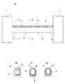
先ず図1は、柱1及び梁2が鉄筋コンクリート造であるコンクリート系ラーメン構造物において、梁部材2の端部の「塑性ヒンジの形成が想定される範囲3」が繊維補強セメント系材料により形成された制震構造の実施形態を概念的に簡略化して示している(請求項1記載の発明)。繊維補強セメント系材料の定義及び内容並びに性質は、上記段落番号[0010]に説明した通りである。
【0022】
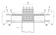
図2は、図1に記載した繊維補強セメント系材料によるコンクリート系構造物の制震構造の更に具体的な実施形態を示す。即ち、梁部材2の両端部の塑性ヒンジの形成が想定される範囲3が繊維補強セメント系材料により形成され、中間部分4を普通コンクリートで形成されたプレキャスト梁部材を予め工場で製作し、これを現場へ搬入し、柱1、1の間へ公知の手法で架設して梁が構築されている(請求項2記載の発明)。繊維補強セメント系材料は、その性質上、現場打ち施工が難しいからである。
【0023】
なお、図示の梁部材2は、その上面に梁主筋5及びフープ筋6の一部を露出させて、後打ちするスラブコンクリートとの一体化施工を容易にする公知のハーフプレキャスト梁部材として構成されたものを示している。
【0024】
次に、図3の実施形態は、図2と同様に梁部材2の両端部の塑性ヒンジの形成が想定される範囲3が繊維補強セメント系材料により形成されているものの、中間部分4は、図3Cに示したように、繊維補強セメント系材料により梁型枠を兼ねるU字形断面として一連に(一体的に)形成されている。そして、前記の溝内に梁主筋5とフープ筋6とから成る梁鉄筋を納めた構成のプレキャスト梁部材として予め工場で製作し、これを現場へ搬入し、柱1、1の間へ公知の手法で架設して梁が構築されている。
【0025】
中間部分4はまた、図3Dに示した例のように、梁鉄筋の下半部を繊維補強セメント系材料の中に埋設した構成でも実施される。
【0026】
いずれにしても、本実施形態の梁部材2は、柱1、1の間へ架設した後、スラブコンクリートの打設に際して、普通コンクリートを中間部分4の前記梁型枠を兼ねるU字形断面部分の溝内に打設して梁が完成される(以上、請求項3記載の発明)。
【0027】
本発明の実施形態によれば、中間部分4を、梁型枠を兼ねるU字形断面として欠き込み形成して現場へ搬入するから、図2の実施形態に比して梁部材の軽量化が格別であり、運搬や設置の取り扱い手間を軽減できるから、コストダウンを図れる利点がある。
【0028】
次に図4に示した実施形態の場合は、梁部材の端部の塑性ヒンジの形成が想定される範囲が繊維補強セメント系材料による梁ブロック30として独立に形成され、この梁ブロック30が柱1の梁取付位置に設置されている。但し、前記梁ブロック30を支持する手段(支保工)の図示は省略した。梁ブロック30は、図4Bに示したように、下端主筋を通す位置にシース孔7…及び梁用のフープ筋6を有する。
【0029】
更に図5は、図4のように柱1の梁取付位置に設置された梁ブロック30の前記シース孔7へ主筋5…を通し、梁中央部の型枠とスラブ型枠を設置した後に、他の梁鉄筋5、6並びにスラブ筋を設置し、スラブコンクリートと共にパネルゾーンを現場でコンクリート打設して一体化させるほか、同時に梁部材2の中間部分も普通コンクリートにより前記梁ブロック30と一連に一体的に構築する方法を示している(以上、請求項4記載の発明)。図4及び図5中の符号8は柱用の鉄筋を示す。
【0030】
図6は、上記繊維補強セメント系材料による梁ブロック30を、そのシース孔へ通したPC鋼材9を柱1をも貫通させて配置し、公知の手法で柱1の梁位置へ圧着して一体化させ、しかる後に、上記図5の例と同様に、梁部材2の中間部分を現場打ちの普通コンクリートにより前記梁ブロック30と一連に一体的に構築する実施形態を示している。
【0031】
次に図7は、柱1の梁接合部分として普通コンクリートで形成された柱梁接合ブロック10に、梁部材2の端部の塑性ヒンジの形成が想定される範囲を繊維補強セメント系材料による梁ブロック30として一体的に形成したものが予め工場でプレキャストコンクリート部材として製作され、これを現場へ搬入し、柱1の上に設置する要領を示している。柱梁接合ブロック10には、柱1の主筋8aを通すシース孔10a…が上下方向に設けられている。また、梁ブロック30には梁鉄筋を構成する主筋5が前記柱梁接合ブロック10を貫通して配筋され、更にフープ筋6…も配置され、且つ、上端主筋5及びフープ筋6の上半部が露出するハーフプレキャスト部材として構成されている。
【0032】
図8は、上記構成の柱梁接合ブロック10が梁ブロック30と合一に柱1の上部(梁取付位置)へ、前記シース孔10aへ柱1の各主筋8aを通す要領で設置された実施形態を示している。その後に、図示を省略したが、梁部材2の中間部分が梁型枠を用いた普通コンクリートにより前記梁ブロックと一連に一体的に構築される(以上、請求項5記載の発明)。
【0033】
【本発明が奏する効果】
請求項1〜5に記載した発明に係る繊維補強セメント系材料によるコンクリート系構造物の制震構造は、梁部材における端部の塑性ヒンジの形成が想定される範囲を繊維補強セメント系材料により形成するので、前記範囲での曲げひび割れ、剪断ひび割れが分散され、鉄筋とコンクリートとの付着強度が高く、塑性回転変形性能が増大するので、より大きな地震エネルギの吸収能力を期待でき、この地震エネルギ吸収性能を適切に把握して設計することにより、当該コンクリート系構造物全体の地震応答を制御する制震構造とすることができる。
【0034】
しかも、他の高価なダンパーの如き制震デバイスを使用する必要がなく、コンクリート系構造物に制震性能を付与することが出来る。したがって、安価に、しかも建物の平面計画に何の影響を及ぼすことなく実施することが出来る。
【0035】
梁端部の塑性ヒンジの形成が想定される範囲を、十分な塑性回転変形性能を付与するために必要な密な配筋も無用であるから、施工性が大きく向上する。
【0036】
しかも繊維補強セメント系材料には、ひび割れを分散させる作用効果があり、損傷が一箇所に集中して起こりにくい為、見た目の損傷も軽減され、地震後の再使用に有利である。
【0037】
更に、構造物のプレキャスト化を進める結果、現場作業の省力化、品質の向上にも寄与するのである。
【図面の簡単な説明】
【図1】本発明に係るコンクリート系構造物の制震構造の基本的な実施形態を示した立面図である。
【図2】Aは梁部材の構造を示す正面図、B、CはA図のb−bおよびc−c断面図である。
【図3】Aは梁部材の異なる構造を示す正面図、B、C、DはA図のb−bおよびc−c断面図である。
【図4】Aは梁ブロックを柱へ設置した状態を示す立面図、BはA図のb−b断面図である。
【図5】前記梁ブロックによる梁部材の構築例を示す立面図である。
【図6】Aは前記梁ブロックによる梁部材の構築例を示す立面図、BはA図のb−b断面図である。
【図7】Aは柱梁接合ブロックと梁ブロックを合一に柱へ設置する要領を示した立面図である。
【図8】前記梁ブロックによる梁部材の構築例を示す立面図である。
【図9】梁端部の塑性回転変形性能についての説明図である。
【図10】コンクリート系構造物一般の例を示す立面図である。
【図11】地震エネルギによる塑性ヒンジの発生状況を示した説明図である。
【図12】コンクリート系構造物にY型ブレースを設置した例を示す立面図である。
【図13】コンクリート系構造物に間柱を設置した例を示す立面図である。
【符号の説明】
1 柱
2 梁部材
3 塑性ヒンジが形成される範囲
4 梁の中間部分
30 梁ブロック
10 柱梁接合ブロック[0001]
TECHNICAL FIELD OF THE INVENTION
The present invention relates to a concrete-based ramen structure assuming a total collapse, by forming a range in which a plastic hinge at an end of a beam member is assumed to be formed with a fiber-reinforced cement-based material, thereby reducing an earthquake response of the structure. It belongs to the technical field of seismic control structure of concrete structure made of fiber reinforced cement based material which can be controlled.
[0002]
[Prior art]
Conventionally, in a concrete ramen structure as illustrated in FIG. 10, energy input to the structure during a large earthquake is, as illustrated in FIG. 11, column bases a on the first floor and beam ends on each floor. The design and construction are performed so as to be absorbed by a plastic hinge (a pin-shaped hinge formed by yielding a cross section of the member due to a load) formed in b. For this reason, in a portion where the formation of a plastic hinge is assumed, brittle fracture is prevented, and shear reinforcing bars and stirrups are densely arranged for the purpose of providing sufficient strength and rotational deformation capability.
[0003]
However, in the case of ordinary reinforced concrete construction, even if reinforcing bars are densely arranged, the dispersibility of cracks is limited, and it is extremely difficult to control damage at a plastic hinge portion where cracks are particularly concentrated.
[0004]
Also, measures are taken to arrange Y-shaped braces c as shown in FIG. 12 and to arrange studs d as shown in FIG. However, since these damping devices are incorporated between the upper and lower beam members, it is a troublesome solution that both the floor plan to secure entrances and passages and the layout plan of braces and studs must be compatible. Exists. In the case of the studs d, it is also a problem that a large number of studs need to be arranged in order to expect a damping effect in a normal building.
[0005]
As a different prior art, the vibration control structure of a reinforced concrete building described in Japanese Patent Application Laid-Open No. 11-22240 discloses a structure in which a gap is provided between both left and right side edges of a shear-resistant wall and a column, and furthermore, the height of the A gap is formed in the hanging wall and the waist wall by dividing the intermediate portion into upper and lower portions, and a damper made of a fiber-reinforced cement material is arranged in the gap to fasten the upper and lower hanging wall and the waist wall. .
[0006]
Next, in the construction method of reinforced concrete columns described in Japanese Patent Publication No. 6-99955, the upper end position of the columns is formed of ordinary concrete, and the lap joints between the main bars of the columns are made of fiber reinforced cement material. A technique for forming is disclosed.
[0007]
Further, the beam-column connection structure described in Japanese Patent Application Laid-Open No. 10-8551 discloses a technique in which the beam-column connection is formed of fiber-reinforced concrete (fiber-reinforced cement-based material).
[0008]
[Problems to be solved by the present invention]
It is known that in a normal reinforced concrete frame structure, when a large repeated load is applied during a large earthquake, plastic rotational deformation is concentrated at the beam end. As shown in exaggeration in FIG. 9, this plastic rotational deformation is caused by bending deformation and bending cracks at the ends of beam members, crushing of concrete, and deterioration of adhesion due to shear deformation and repeated loads near dangerous cross sections of beams. This is due to the pull-out of the tensile-side steel material (beam main bar) resulting from the above. If the amount of reinforcing bars is small, the proof stress rapidly decreases, so that the plastic deformation rotation capability is small and large energy absorption capability cannot be expected. In addition, even if the structure can be used only by simple repair after the earthquake, it is a problem to give an impression that the apparent damage is severe.
[0009]
As an improvement measure relating to such plastic rotation deformation of the beam end, the invention relating to the vibration control structure of a reinforced concrete building described in the above-mentioned Japanese Patent Application Laid-Open No. 11-22240, and Japanese Patent Publication No. 6-99955 is described. The invention relating to the method of constructing a reinforced concrete column and the invention relating to the beam-column connection structure described in JP-A-10-8551 have different technical ideas and are powerless.
[0010]
Next, a so-called fiber-reinforced cementitious material (or fiber-reinforced mortar) in which short fibers such as carbon fiber, aramid fiber, glass fiber, vinylon fiber, polypropylene fiber, and steel fiber are mixed as a reinforcing material for concrete is used in conventional ordinary concrete. Compared with, it is known that the cracks at the time of tension are dispersed, and that the fibers have an effect of restraining the width of the cracks from opening, thereby exhibiting excellent apparent tensile strength and tensile toughness. As already explained in the section of the prior art, it is already used as a part of a concrete structure.
[0011]
Therefore, when forming at least the range in which the formation of the plastic hinge is assumed at the beam end of the concrete frame structure by the fiber-reinforced cementitious material, bending cracks and shear cracks of the plastic hinge portion are dispersed, and the fiber The opening of the crack is restrained from opening, so that so-called peeling of the concrete does not occur, and a sharp decrease in the proof stress does not occur. Further, the bonding strength between the reinforcing steel and the concrete is improved, and eventually, the plastic deformation rotation ability is increased. Therefore, a larger energy absorbing ability can be expected. Therefore, the present invention has been made focusing on the fact that the seismic response of the whole building can be controlled by appropriately grasping and designing the energy absorption amount.
[0012]
Another problem to be solved is that fiber-reinforced cementitious materials are difficult to cast in place due to their properties.
[0013]
Therefore, an object of the present invention is to form the `` at least a range in which the formation of a plastic hinge is assumed '' at the beam end of a concrete frame structure assuming total collapse by the fiber-reinforced cement material, Vibration control that increases the plastic deformation rotation capacity, enables seismic response control of the entire building, and eliminates the need for installation of vibration control devices that affect the floor plan of openings, etc., and adds a vibration control effect to structures. Is to provide a structure.
[0014]
The next object of the present invention is to form a range in which the formation of a plastic hinge is assumed by the fiber-reinforced cementitious material, thereby increasing the deformation capacity while reducing the amount of shear reinforcement in the assumed portion of the plastic hinge, By providing a large seismic energy absorption capacity as a whole, with excellent crack dispersibility, reducing the degree of damage, and providing a seismic control structure that can be reused with only simple repairs after an earthquake. is there.
[0015]
[Means for Solving the Problems]
As means for solving the above-mentioned problems of the prior art, as a means for damping a concrete structure using a fiber-reinforced cement material according to the invention of
In concrete ramen structures,
The range in which the formation of the plastic hinge at the end of the beam member is assumed is made of a fiber-reinforced cement-based material.
[0016]
According to a second aspect of the present invention, there is provided a vibration control structure for a concrete structure using the fiber reinforced cement material according to the first aspect,
The range in which the plastic hinges at both ends of the beam member are assumed to be formed is formed of a fiber-reinforced cementitious material, and the beam is constructed of a precast beam member whose intermediate portion is formed of ordinary concrete.
[0017]
According to a third aspect of the present invention, there is provided a vibration control structure for a concrete structure using the fiber-reinforced cement material according to the first aspect,
A range in which the plastic hinges at both ends of the beam member are assumed to be formed is formed of a fiber-reinforced cementitious material, and the intermediate portion is a series of U-shaped cross-sections of the same fiber-reinforced cementitious material which also serve as a beam form. A beam is framed by the beam member, and ordinary concrete is cast into a U-shaped cross-section that also serves as the beam formwork.
[0018]
According to a fourth aspect of the present invention, there is provided a vibration control structure for a concrete structure using the fiber-reinforced cementitious material according to the first aspect,
The range in which the formation of the plastic hinge at the end of the beam member is assumed is formed as a beam block made of fiber-reinforced cementitious material, and the beam block is installed at the beam position of the column. It is characterized by being constructed integrally with the beam block by ordinary concrete using a frame.
[0019]
According to a fifth aspect of the present invention, there is provided a vibration control structure for a concrete structure using the fiber-reinforced cement material according to the first aspect,
In the column-beam joint block made of ordinary concrete as the beam joint part of the column, the range where the formation of the plastic hinge at the end of the beam member is assumed to be integrally formed as a beam block made of fiber reinforced cement material The column-beam joint block is installed on the column united with the beam block, and the intermediate portion of the beam member is integrally formed integrally with the beam block by ordinary concrete using a beam formwork. It is characterized by.
[0020]
DETAILED DESCRIPTION OF THE INVENTION
Hereinafter, a vibration damping structure of a concrete structure using a fiber reinforced cement material according to the first to fifth aspects of the present invention will be described with reference to the embodiments shown in FIGS.
[0021]
First, FIG. 1 shows that in a concrete frame structure in which the
[0022]
FIG. 2 shows a more specific embodiment of the vibration damping structure of a concrete structure using the fiber reinforced cement material shown in FIG. That is, a
[0023]
The illustrated
[0024]
Next, in the embodiment of FIG. 3, as in FIG. 2, the
[0025]
The
[0026]
In any case, the
[0027]
According to the embodiment of the present invention, since the
[0028]
Next, in the case of the embodiment shown in FIG. 4, the range in which the formation of the plastic hinge at the end of the beam member is assumed is independently formed as a
[0029]
Further, FIG. 5 shows that, after the
[0030]
FIG. 6 shows a
[0031]
Next, FIG. 7 shows a range in which a plastic hinge at the end of the
[0032]
FIG. 8 shows an embodiment in which the beam-column
[0033]
[Effects of the present invention]
In the vibration damping structure of a concrete structure using the fiber-reinforced cement material according to the first to fifth aspects of the present invention, the range in which the formation of the plastic hinge at the end of the beam member is assumed to be formed by the fiber-reinforced cement material. Therefore, bending cracks and shear cracks in the above range are dispersed, the bonding strength between the reinforcing steel and the concrete is high, and the plastic rotational deformation performance is increased. By properly grasping and designing the performance, it is possible to provide a vibration control structure that controls the earthquake response of the entire concrete structure.
[0034]
Moreover, it is not necessary to use a damping device such as another expensive damper, and the damping performance can be imparted to the concrete structure. Therefore, it can be implemented at low cost and without any influence on the floor plan of the building.
[0035]
In the range in which the plastic hinge at the end of the beam is assumed to be formed, dense rebars necessary for imparting sufficient plastic rotational deformation performance are unnecessary, so that the workability is greatly improved.
[0036]
Moreover, the fiber-reinforced cementitious material has an effect of dispersing cracks, and since damage is hardly concentrated at one place, visual damage is also reduced, which is advantageous for reuse after an earthquake.
[0037]
Furthermore, as a result of promoting the precasting of the structure, it also contributes to labor saving and quality improvement of on-site work.
[Brief description of the drawings]
FIG. 1 is an elevation view showing a basic embodiment of a vibration control structure for a concrete structure according to the present invention.
2A is a front view showing a structure of a beam member, and FIGS. 2B and 2C are cross-sectional views taken along line bb and cc of FIG.
3A is a front view showing a different structure of a beam member, and FIGS. 3B, 3C, and 3D are cross-sectional views taken along line bb and cc of FIG.
FIG. 4A is an elevational view showing a state where a beam block is installed on a pillar, and FIG. 4B is a sectional view taken along line bb of FIG.
FIG. 5 is an elevation view showing an example of construction of a beam member by the beam block.
6A is an elevation view showing an example of building a beam member by the beam block, and FIG. 6B is a sectional view taken along line bb of FIG.
FIG. 7A is an elevation view showing a procedure for installing a beam-column joint block and a beam block together on a column.
FIG. 8 is an elevation view showing an example of building a beam member by the beam block.
FIG. 9 is an explanatory diagram of plastic rotational deformation performance of a beam end.
FIG. 10 is an elevation view showing a general example of a concrete structure.
FIG. 11 is an explanatory diagram showing a state of generation of a plastic hinge due to seismic energy.
FIG. 12 is an elevation view showing an example in which a Y-type brace is installed on a concrete structure.
FIG. 13 is an elevation view showing an example in which studs are installed on a concrete structure.
[Explanation of symbols]
DESCRIPTION OF
Claims (5)
梁部材の端部の塑性ヒンジの形成が想定される範囲が繊維補強セメント系材料により形成されていることを特徴とする、繊維補強セメント系材料によるコンクリート系構造物の制震構造。In concrete ramen structures,
A vibration damping structure for a concrete structure made of a fiber reinforced cement material, wherein a range in which a plastic hinge at an end of a beam member is assumed is formed of a fiber reinforced cement material.
Priority Applications (1)
| Application Number | Priority Date | Filing Date | Title |
|---|---|---|---|
| JP2002202585A JP3999591B2 (en) | 2002-07-11 | 2002-07-11 | Seismic control structure of concrete structure with fiber reinforced cementitious material |
Applications Claiming Priority (1)
| Application Number | Priority Date | Filing Date | Title |
|---|---|---|---|
| JP2002202585A JP3999591B2 (en) | 2002-07-11 | 2002-07-11 | Seismic control structure of concrete structure with fiber reinforced cementitious material |
Publications (2)
| Publication Number | Publication Date |
|---|---|
| JP2004044197A true JP2004044197A (en) | 2004-02-12 |
| JP3999591B2 JP3999591B2 (en) | 2007-10-31 |
Family
ID=31708729
Family Applications (1)
| Application Number | Title | Priority Date | Filing Date |
|---|---|---|---|
| JP2002202585A Expired - Fee Related JP3999591B2 (en) | 2002-07-11 | 2002-07-11 | Seismic control structure of concrete structure with fiber reinforced cementitious material |
Country Status (1)
| Country | Link |
|---|---|
| JP (1) | JP3999591B2 (en) |
Cited By (6)
| Publication number | Priority date | Publication date | Assignee | Title |
|---|---|---|---|---|
| JP2008169672A (en) * | 2007-01-15 | 2008-07-24 | Ohbayashi Corp | Construction method of concrete beam, concrete beam, joining method of pc beam member and joining structure of pc beam member |
| JP2009079397A (en) * | 2007-09-26 | 2009-04-16 | Taisei Corp | Building with semi-rigidly joined column base |
| JP2010185181A (en) * | 2009-02-10 | 2010-08-26 | Shimizu Corp | Structure for joining concrete members |
| JP2014163082A (en) * | 2013-02-22 | 2014-09-08 | Takenaka Komuten Co Ltd | Column-beam frame |
| JP2018131885A (en) * | 2017-02-18 | 2018-08-23 | 株式会社安藤・間 | Joining structure and joining method of precast concrete beam members |
| CN113404009A (en) * | 2021-07-15 | 2021-09-17 | 长江水利委员会长江科学院 | Novel concrete panel structure of rock-fill dam and construction method |
Families Citing this family (2)
| Publication number | Priority date | Publication date | Assignee | Title |
|---|---|---|---|---|
| JP2009144344A (en) * | 2007-12-11 | 2009-07-02 | Shimizu Corp | Reinforced concrete body |
| CN105401655B (en) * | 2015-12-16 | 2017-07-28 | 南京工业大学 | A kind of automatic control power consumption unbonded prestressed reinforced concrete frame |
-
2002
- 2002-07-11 JP JP2002202585A patent/JP3999591B2/en not_active Expired - Fee Related
Cited By (6)
| Publication number | Priority date | Publication date | Assignee | Title |
|---|---|---|---|---|
| JP2008169672A (en) * | 2007-01-15 | 2008-07-24 | Ohbayashi Corp | Construction method of concrete beam, concrete beam, joining method of pc beam member and joining structure of pc beam member |
| JP2009079397A (en) * | 2007-09-26 | 2009-04-16 | Taisei Corp | Building with semi-rigidly joined column base |
| JP2010185181A (en) * | 2009-02-10 | 2010-08-26 | Shimizu Corp | Structure for joining concrete members |
| JP2014163082A (en) * | 2013-02-22 | 2014-09-08 | Takenaka Komuten Co Ltd | Column-beam frame |
| JP2018131885A (en) * | 2017-02-18 | 2018-08-23 | 株式会社安藤・間 | Joining structure and joining method of precast concrete beam members |
| CN113404009A (en) * | 2021-07-15 | 2021-09-17 | 长江水利委员会长江科学院 | Novel concrete panel structure of rock-fill dam and construction method |
Also Published As
| Publication number | Publication date |
|---|---|
| JP3999591B2 (en) | 2007-10-31 |
Similar Documents
| Publication | Publication Date | Title |
|---|---|---|
| US11680401B2 (en) | Precast wall panels and method of erecting a high-rise building using the panels | |
| US8074414B2 (en) | Precast wall panels and method of erecting a high-rise building using the panels | |
| KR101027393B1 (en) | Longitudinal and/or transverse seismic reinforcing method for masonry walls | |
| KR100858963B1 (en) | H-shape block, manufacturing method of prestressed precast beams using h-shape block, and joining method of prestressed precast beams to columns using h-shape block | |
| JP3999591B2 (en) | Seismic control structure of concrete structure with fiber reinforced cementitious material | |
| JPH03250130A (en) | Constructing method using reinforced steel framed reinforced half-precast concrete beam without main reinforcing steel | |
| KR20140137665A (en) | Enlarged capital of steel framed reinforced concrete column and method for construction of the enlarged capital | |
| KR20130117204A (en) | Earthquake-resistant frame and seismic retrofit method for building using the same | |
| JP3909488B2 (en) | Seismic reinforcement structure of existing building and its construction method | |
| JP3942973B2 (en) | Seismic control structure of concrete structure with fiber reinforced cementitious material | |
| JP4660810B2 (en) | Boundary beam damper | |
| JP5726675B2 (en) | Reinforcement structure of existing building | |
| JPH02252831A (en) | Pre-fabricated cruciform beam construction method | |
| KR102606899B1 (en) | Wall structure using combined precast foundation reinforcement network and precast wall using and its construction method | |
| JP2620118B2 (en) | Net formwork method for walls and floors | |
| JP2000073448A (en) | Connection method and structure for precast concrete beam and column | |
| JP7220627B2 (en) | Damping structure of building and its construction method | |
| JP7270095B2 (en) | Mixed structure of reinforced concrete columns and steel beams | |
| JPH11152908A (en) | Earthquake resistant reinforcing structure for existing building, and its method | |
| JP2006169837A (en) | Column-beam joint structure of reinforced concrete construction | |
| JP3830062B2 (en) | Seismic reinforcement method for reinforced concrete buildings | |
| KR20110124005A (en) | Improved steel beam having through-hole, shear reinforcing structure using the same and its construction method | |
| JPH1061204A (en) | Earthquake resisting repair method for existing building | |
| JP4658826B2 (en) | SC wall block, SC wall block manufacturing method, and SC structure construction method | |
| JP2578671B2 (en) | Column and beam construction method |
Legal Events
| Date | Code | Title | Description |
|---|---|---|---|
| A621 | Written request for application examination |
Free format text: JAPANESE INTERMEDIATE CODE: A621 Effective date: 20041201 |
|
| A977 | Report on retrieval |
Free format text: JAPANESE INTERMEDIATE CODE: A971007 Effective date: 20060808 |
|
| A131 | Notification of reasons for refusal |
Free format text: JAPANESE INTERMEDIATE CODE: A131 Effective date: 20060829 |
|
| A521 | Written amendment |
Free format text: JAPANESE INTERMEDIATE CODE: A523 Effective date: 20061027 |
|
| A131 | Notification of reasons for refusal |
Free format text: JAPANESE INTERMEDIATE CODE: A131 Effective date: 20070206 |
|
| A521 | Written amendment |
Free format text: JAPANESE INTERMEDIATE CODE: A523 Effective date: 20070403 |
|
| TRDD | Decision of grant or rejection written | ||
| A01 | Written decision to grant a patent or to grant a registration (utility model) |
Free format text: JAPANESE INTERMEDIATE CODE: A01 Effective date: 20070724 |
|
| A61 | First payment of annual fees (during grant procedure) |
Free format text: JAPANESE INTERMEDIATE CODE: A61 Effective date: 20070809 |
|
| R150 | Certificate of patent or registration of utility model |
Free format text: JAPANESE INTERMEDIATE CODE: R150 |
|
| FPAY | Renewal fee payment (event date is renewal date of database) |
Free format text: PAYMENT UNTIL: 20100817 Year of fee payment: 3 |
|
| FPAY | Renewal fee payment (event date is renewal date of database) |
Free format text: PAYMENT UNTIL: 20110817 Year of fee payment: 4 |
|
| FPAY | Renewal fee payment (event date is renewal date of database) |
Free format text: PAYMENT UNTIL: 20110817 Year of fee payment: 4 |
|
| FPAY | Renewal fee payment (event date is renewal date of database) |
Free format text: PAYMENT UNTIL: 20120817 Year of fee payment: 5 |
|
| FPAY | Renewal fee payment (event date is renewal date of database) |
Free format text: PAYMENT UNTIL: 20130817 Year of fee payment: 6 |
|
| LAPS | Cancellation because of no payment of annual fees |