JP2004042013A - Method of treating volatile hydrocarbon-containing exhaust gas, and equipment for implementing the method - Google Patents
Method of treating volatile hydrocarbon-containing exhaust gas, and equipment for implementing the method Download PDFInfo
- Publication number
- JP2004042013A JP2004042013A JP2002308497A JP2002308497A JP2004042013A JP 2004042013 A JP2004042013 A JP 2004042013A JP 2002308497 A JP2002308497 A JP 2002308497A JP 2002308497 A JP2002308497 A JP 2002308497A JP 2004042013 A JP2004042013 A JP 2004042013A
- Authority
- JP
- Japan
- Prior art keywords
- gas
- exhaust gas
- adsorption
- adsorbent
- volatile
- Prior art date
- Legal status (The legal status is an assumption and is not a legal conclusion. Google has not performed a legal analysis and makes no representation as to the accuracy of the status listed.)
- Granted
Links
Images


Classifications
-
- B—PERFORMING OPERATIONS; TRANSPORTING
- B01—PHYSICAL OR CHEMICAL PROCESSES OR APPARATUS IN GENERAL
- B01D—SEPARATION
- B01D53/00—Separation of gases or vapours; Recovering vapours of volatile solvents from gases; Chemical or biological purification of waste gases, e.g. engine exhaust gases, smoke, fumes, flue gases, aerosols
- B01D53/02—Separation of gases or vapours; Recovering vapours of volatile solvents from gases; Chemical or biological purification of waste gases, e.g. engine exhaust gases, smoke, fumes, flue gases, aerosols by adsorption, e.g. preparative gas chromatography
- B01D53/04—Separation of gases or vapours; Recovering vapours of volatile solvents from gases; Chemical or biological purification of waste gases, e.g. engine exhaust gases, smoke, fumes, flue gases, aerosols by adsorption, e.g. preparative gas chromatography with stationary adsorbents
- B01D53/0407—Constructional details of adsorbing systems
- B01D53/0423—Beds in columns
-
- B—PERFORMING OPERATIONS; TRANSPORTING
- B01—PHYSICAL OR CHEMICAL PROCESSES OR APPARATUS IN GENERAL
- B01D—SEPARATION
- B01D53/00—Separation of gases or vapours; Recovering vapours of volatile solvents from gases; Chemical or biological purification of waste gases, e.g. engine exhaust gases, smoke, fumes, flue gases, aerosols
- B01D53/02—Separation of gases or vapours; Recovering vapours of volatile solvents from gases; Chemical or biological purification of waste gases, e.g. engine exhaust gases, smoke, fumes, flue gases, aerosols by adsorption, e.g. preparative gas chromatography
- B01D53/04—Separation of gases or vapours; Recovering vapours of volatile solvents from gases; Chemical or biological purification of waste gases, e.g. engine exhaust gases, smoke, fumes, flue gases, aerosols by adsorption, e.g. preparative gas chromatography with stationary adsorbents
- B01D53/047—Pressure swing adsorption
-
- B—PERFORMING OPERATIONS; TRANSPORTING
- B01—PHYSICAL OR CHEMICAL PROCESSES OR APPARATUS IN GENERAL
- B01D—SEPARATION
- B01D53/00—Separation of gases or vapours; Recovering vapours of volatile solvents from gases; Chemical or biological purification of waste gases, e.g. engine exhaust gases, smoke, fumes, flue gases, aerosols
- B01D53/34—Chemical or biological purification of waste gases
- B01D53/46—Removing components of defined structure
- B01D53/72—Organic compounds not provided for in groups B01D53/48 - B01D53/70, e.g. hydrocarbons
-
- B—PERFORMING OPERATIONS; TRANSPORTING
- B01—PHYSICAL OR CHEMICAL PROCESSES OR APPARATUS IN GENERAL
- B01D—SEPARATION
- B01D2253/00—Adsorbents used in seperation treatment of gases and vapours
- B01D2253/10—Inorganic adsorbents
- B01D2253/102—Carbon
-
- B—PERFORMING OPERATIONS; TRANSPORTING
- B01—PHYSICAL OR CHEMICAL PROCESSES OR APPARATUS IN GENERAL
- B01D—SEPARATION
- B01D2253/00—Adsorbents used in seperation treatment of gases and vapours
- B01D2253/10—Inorganic adsorbents
- B01D2253/106—Silica or silicates
- B01D2253/108—Zeolites
-
- B—PERFORMING OPERATIONS; TRANSPORTING
- B01—PHYSICAL OR CHEMICAL PROCESSES OR APPARATUS IN GENERAL
- B01D—SEPARATION
- B01D2253/00—Adsorbents used in seperation treatment of gases and vapours
- B01D2253/30—Physical properties of adsorbents
- B01D2253/302—Dimensions
- B01D2253/308—Pore size
-
- B—PERFORMING OPERATIONS; TRANSPORTING
- B01—PHYSICAL OR CHEMICAL PROCESSES OR APPARATUS IN GENERAL
- B01D—SEPARATION
- B01D2256/00—Main component in the product gas stream after treatment
- B01D2256/10—Nitrogen
-
- B—PERFORMING OPERATIONS; TRANSPORTING
- B01—PHYSICAL OR CHEMICAL PROCESSES OR APPARATUS IN GENERAL
- B01D—SEPARATION
- B01D2257/00—Components to be removed
- B01D2257/70—Organic compounds not provided for in groups B01D2257/00 - B01D2257/602
- B01D2257/702—Hydrocarbons
-
- B—PERFORMING OPERATIONS; TRANSPORTING
- B01—PHYSICAL OR CHEMICAL PROCESSES OR APPARATUS IN GENERAL
- B01D—SEPARATION
- B01D2257/00—Components to be removed
- B01D2257/70—Organic compounds not provided for in groups B01D2257/00 - B01D2257/602
- B01D2257/708—Volatile organic compounds V.O.C.'s
-
- B—PERFORMING OPERATIONS; TRANSPORTING
- B01—PHYSICAL OR CHEMICAL PROCESSES OR APPARATUS IN GENERAL
- B01D—SEPARATION
- B01D2259/00—Type of treatment
- B01D2259/40—Further details for adsorption processes and devices
- B01D2259/40011—Methods relating to the process cycle in pressure or temperature swing adsorption
- B01D2259/40077—Direction of flow
- B01D2259/40081—Counter-current
-
- B—PERFORMING OPERATIONS; TRANSPORTING
- B01—PHYSICAL OR CHEMICAL PROCESSES OR APPARATUS IN GENERAL
- B01D—SEPARATION
- B01D2259/00—Type of treatment
- B01D2259/40—Further details for adsorption processes and devices
- B01D2259/40083—Regeneration of adsorbents in processes other than pressure or temperature swing adsorption
- B01D2259/40088—Regeneration of adsorbents in processes other than pressure or temperature swing adsorption by heating
- B01D2259/4009—Regeneration of adsorbents in processes other than pressure or temperature swing adsorption by heating using hot gas
-
- B—PERFORMING OPERATIONS; TRANSPORTING
- B01—PHYSICAL OR CHEMICAL PROCESSES OR APPARATUS IN GENERAL
- B01D—SEPARATION
- B01D2259/00—Type of treatment
- B01D2259/40—Further details for adsorption processes and devices
- B01D2259/402—Further details for adsorption processes and devices using two beds
-
- B—PERFORMING OPERATIONS; TRANSPORTING
- B01—PHYSICAL OR CHEMICAL PROCESSES OR APPARATUS IN GENERAL
- B01D—SEPARATION
- B01D2259/00—Type of treatment
- B01D2259/40—Further details for adsorption processes and devices
- B01D2259/414—Further details for adsorption processes and devices using different types of adsorbents
- B01D2259/4141—Further details for adsorption processes and devices using different types of adsorbents within a single bed
- B01D2259/4145—Further details for adsorption processes and devices using different types of adsorbents within a single bed arranged in series
- B01D2259/4148—Multiple layers positioned apart from each other
-
- B—PERFORMING OPERATIONS; TRANSPORTING
- B01—PHYSICAL OR CHEMICAL PROCESSES OR APPARATUS IN GENERAL
- B01D—SEPARATION
- B01D53/00—Separation of gases or vapours; Recovering vapours of volatile solvents from gases; Chemical or biological purification of waste gases, e.g. engine exhaust gases, smoke, fumes, flue gases, aerosols
- B01D53/02—Separation of gases or vapours; Recovering vapours of volatile solvents from gases; Chemical or biological purification of waste gases, e.g. engine exhaust gases, smoke, fumes, flue gases, aerosols by adsorption, e.g. preparative gas chromatography
- B01D53/04—Separation of gases or vapours; Recovering vapours of volatile solvents from gases; Chemical or biological purification of waste gases, e.g. engine exhaust gases, smoke, fumes, flue gases, aerosols by adsorption, e.g. preparative gas chromatography with stationary adsorbents
- B01D53/0407—Constructional details of adsorbing systems
- B01D53/0431—Beds with radial gas flow
-
- B—PERFORMING OPERATIONS; TRANSPORTING
- B01—PHYSICAL OR CHEMICAL PROCESSES OR APPARATUS IN GENERAL
- B01D—SEPARATION
- B01D53/00—Separation of gases or vapours; Recovering vapours of volatile solvents from gases; Chemical or biological purification of waste gases, e.g. engine exhaust gases, smoke, fumes, flue gases, aerosols
- B01D53/02—Separation of gases or vapours; Recovering vapours of volatile solvents from gases; Chemical or biological purification of waste gases, e.g. engine exhaust gases, smoke, fumes, flue gases, aerosols by adsorption, e.g. preparative gas chromatography
- B01D53/04—Separation of gases or vapours; Recovering vapours of volatile solvents from gases; Chemical or biological purification of waste gases, e.g. engine exhaust gases, smoke, fumes, flue gases, aerosols by adsorption, e.g. preparative gas chromatography with stationary adsorbents
- B01D53/0407—Constructional details of adsorbing systems
- B01D53/0446—Means for feeding or distributing gases
-
- Y—GENERAL TAGGING OF NEW TECHNOLOGICAL DEVELOPMENTS; GENERAL TAGGING OF CROSS-SECTIONAL TECHNOLOGIES SPANNING OVER SEVERAL SECTIONS OF THE IPC; TECHNICAL SUBJECTS COVERED BY FORMER USPC CROSS-REFERENCE ART COLLECTIONS [XRACs] AND DIGESTS
- Y02—TECHNOLOGIES OR APPLICATIONS FOR MITIGATION OR ADAPTATION AGAINST CLIMATE CHANGE
- Y02C—CAPTURE, STORAGE, SEQUESTRATION OR DISPOSAL OF GREENHOUSE GASES [GHG]
- Y02C20/00—Capture or disposal of greenhouse gases
- Y02C20/20—Capture or disposal of greenhouse gases of methane
Abstract
Description
【0001】
【発明の属する技術分野】
本発明は、第一に、揮発性炭化水素を含む排ガスから吸・脱着法によって揮発性炭化水素を分離し、該ガスを、清浄なガスとして吸着塔の排出口から取り出し、大気中に放散させるための、揮発性炭化水素含有排ガスの処理方法及び該方法を実施するための装置に関する。
【0002】
更に詳述すれば、従来から、公害防止上、法的に義務ずけられた排出濃度の規制値を満足すべく、排ガス中の揮発性炭化水素を吸着法によって除去する手段は殆どが公知である(特許文献1〜5参照)。
これら公知の方法で使われている吸着剤は、粒状活性炭,繊維状活性炭,疎水性シリカゲル,合成ゼオライトの4種類である。活性炭について言えば、従来から最も広く使われてはいるものの、優れた吸着性能をもつ反面、脱着性能が悪く、殆どがスチームによる加熱脱着である。最近に至って、パージガスのみで脱着できる、若しくは、真空手段だけで脱着可能な新規な活性炭が開発された。この活性炭は、中国では、褐炭や泥炭をベースにして作られており、オランダでは、オリーブの種子をベースにし、これを燐酸処理により賦活したものが市販されている。このものは、細孔の大きさがナノメーターのオーダーであって、“ナノホールカーボン”と称して差し支えない。
【0003】
本発明は、脱着にスチームを使う必要のない上記活性炭を単独に、若しくは汎用されている疎水性シリカゲルや合成ゼオライトと組み合わせて使用する新規な吸着方法による“揮発性炭化水素含有排ガスの処理方法及び該方法を実施するための装置”に関する。
具体的には、排ガス中に含まれるエチレンやプロピレン,ベンゼンやトルエン,メチルエチルケトン,トリクロロエチレン,オクタジエン,ヘキセン等の揮発性炭化水素を吸着処理して、該ガス中に同伴される上記揮発性炭化水素の濃度を好ましくは10ppm以下にして排出するための方法および装置に関する。
【0004】
本発明は、第二に、(1)前記揮発性炭化水素を含む排ガスとして、“回収を目的とする有用な成分を含む多成分系炭化水素ガス”を対象とし、該ガスから目的とする成分のみを分離回収(単離回収)する目的で行う、排ガスの処理方法及び該方法を実施するための装置に関する。
【0005】
上記(1)の処理方法及び該方法を実施するための装置について、具体的な一例として“合成ゴムの製造時における排ガスの処理例”を挙げて説明する。
合成ゴムを製造する際に用いられる原料ガスとしては、エチレンやプロピレン或いはブタジエン等、多岐に亘るオレフイン系炭化水素を単独に、若しくは、これらを組み合わせて重合させることによって、ブチルゴムやブタジエンゴム、或いはエチレン・プロピレンゴム等の製品が得られていることは周知であるが、かかる重合反応時に発生する排ガス中には、廃棄してよいガス(副生ガス)と回収すべきガス(未反応ガス)とが共存する。例えば、ある種の重合反応系では、排ガス中にエチレンとブテンが共存する。この際、回収し再利用したいのは、未反応のエチレンガスであり、廃棄したいのは、副生したブテンガスであって、しかも再利用を図る未反応エチレンは純度99.9%以上で回収する必要がある。しかし、従来技術では、液化させずに気相のままの状態で分離し回収する技術がなかったために、焼却処分しているのが現状である。
本発明は、上記未反応エチレンのような有用な成分を含む多成分系炭化水素ガスを対象とし、該ガスから有用成分のみを高純度で分離回収(単離回収)する目的で行う、排ガスの処理方法及び該方法を実施するための装置に関する。
【0006】
また、(2)前記揮発性炭化水素を含む排ガスとして、“揮発性炭化水素の不純ガス乃至汚染ガスを含む不活性ガス”を対象とし、該不純ガス乃至汚染ガス含有不活性ガスから吸・脱着法によって揮発性炭化水素を分離し、清浄な不活性ガスとして吸着塔の排出口から回収するための、揮発性炭化水素含有排ガス(揮発性炭化水素の不純ガス乃至汚染ガス含有不活性ガス)の処理方法及び該方法を実施するための装置に関する。
【0007】
上記(2)の処理方法及び該方法を実施するための装置について具体的に説明すると、これは、不活性ガスの存在下で反応を行わせたり、製品を不活性ガス(例えば窒素ガス)で洗浄する際に同伴する不純ガス乃至汚染ガス(揮発性の反応物質や未反応原料物質、或いは、反応生成物等の不純ガス乃至汚染ガス)、例えば、エチレンやプロピレン,ベンゼンやトルエン,メチルエチルケトン,トリクロロエチレン,オクタジエン,ヘキセン等の揮発性の不純ガス乃至汚染ガスを含む不活性ガスの精製処理に係り、該不活性ガス中に同伴される上記不純ガス乃至汚染ガスの成分濃度を100ppm以下、好ましくは10ppm以下にして、換言すれば、不活性ガスの純度を望むべくは99%以上にして、該不活性ガスを再利用するための、前記方法および装置に関する。ここで言う“不活性ガス”とは、窒素や炭酸ガス,ヘリウムやキセノン,それにフロンガス等であって、単独では活性が著しく乏しい化学物質を総称している。
【0008】
【従来の技術】
現在我が国において用いられている化学商品は、2万種類にのぼると云われ、その多くが化学工場や石油化学工場,製薬工場等で作られている。かかる製造工程から直接外部に排出されるガスは、前記のように多種多様な揮発性炭化水素を含んでいる。また、上記工程で得られた製品についても、その貯蔵,運搬,荷揚げ,荷下ろしの際に空気と混ざって、同様に大気中に放散される。
【0009】
一方、上記化学商品の多くは、基礎化学物質である芳香族系や脂肪族系,複素環状系,有機ハロゲン系の基礎有機薬品を原料として用い、これらを触媒下で反応させて目的とする製品を得ている。
この際の反応工程では、窒素や炭酸ガス,一酸化炭素,ヘリウムガスのような不活性ガスの存在下で反応を進める場合が多い。その場合、反応終了後、使用した不活性ガスが反応生成物に汚染されて再利用できず、通常は、そのまま廃棄処分にしているのが現状である。また、半導体製造工場等でも、エツチングに使用するエツチング剤(例えばルテニウムジオクタジエン等)は、上記と同様に、廃棄処分が困難なガス成分からなるものが数多い。或いは、石油化学プロセスの反応過程で生成する反応系ガスから、望ましくない不純ガスを分離して、目的成分を高純度で得ようとするケースもある。
【0010】
ところで、揮発性炭化水素で汚染された排ガス(「汚染された不活性ガス」を含む。以下同じ。)をそのまま大気中に放散すれば、不純ガス乃至汚染ガスとして大気公害の元凶物質の一つである、ベンゼンやトルエン,塩化メチレン,メチルエチルケトン,トリクロロエチレン,フロンなどの有害なガスを同伴しているために、排出濃度に関する法的規制に違反することになる。このため、上記排ガスの扱いについて、前述の各工場においていずれも苦慮しているのが現状である。
【0011】
従来、かかる排ガスの処理方法としては、不純物乃至汚染ガスを含むこのガスを水洗浄、乃至は、酸やアルカリで洗浄した後、沸点の高いスポンジオイル(例えば重油)で洗浄するか、或いは、従来型の活性炭を用いて混在する不純ガスを吸着させた後、破過する前に該活性炭を取り出して産廃処理するといった方法で処理していた。
また、混在する汚染ガスとして、ジエン類のような重合成分を含む排ガスであれば、従来型の活性炭は使用できないので、その場合、各地方自治体の条例で定められた排出濃度以下になるように汚染ガスを大気で薄めて、姑息な手段ではあるが、そのまま大気中に放散させていた。
【0012】
しかしながら、水洗浄,酸やアルカリ洗浄或いは重油洗浄,更には従来型の活性炭の再生にスチームを使う場合は、いずれも排水処理設備が不可欠であった。
活性汚泥で処理するにしても、BODの値は排水基準に合格するが、CODの値が低下しないため大量の曝気が必要となる。この場合、排水中に放出されて水に混入した上記不純ガス乃至汚染ガスは、曝気に同伴されて大気中に再度放散される。この濃度は、曝気の量にもよるが、通常100ppm以下と比較的薄く、従来の地方自治体が定めている“排出濃度規制値250ppm以下(東京都の場合)”を満足しているため、問題が生じなかった。
【0013】
ところが、平成14年4月(2002年4月)以降に実施されることが決まっている「特定化学物質の環境への排出量の把握及び管理の改善に関する法律」、いわゆる“PRTR法”は、従来から慣行されてきた排出濃度の規制ではなく、工場全体の排出総量規制であって、前記したように、曝気の際に大量の空気に薄めて排出することができなくなる。
かかる状況に鑑み、本発明者等は、揮発性炭化水素を含む排ガスを、従前とは異なった新規な吸着剤を用いて処理し、排ガス中に混在するアルコール類や芳香族,パラフイン類,オレフイン類等々を除去してゼロエミツションを達成させるという“公害防止上の観点”から、本発明を完成させたものである。また、本発明者等は、上記揮発性炭化水素含有排ガスとして、「回収を目的とする有用な成分を含む多成分系炭化水素ガス」または「不純ガス乃至汚染ガス含有不活性ガス」を対象とし、該ガスからの「有用な成分」または「不活性ガス」の“分離・回収・再利用上の観点”から、本発明を完成させたものである。
【0014】
前述の目的を達成するための手段としては、排ガス中に含まれる揮発性炭化水素がガソリンベーパーであったり、水に可溶なアルコール類であったり、重合性に富むオレフインガスであったり、多岐多様に亘っているため、吸着剤の選定には細心の注意が必要である。
【0015】
ところで、前述のような目的で、排ガス中の汚染成分を分離する方法としては、従来から深冷分離,蒸留,吸収等々の手法が用いられている。
また、吸着分離法に関し、該分野で広く用いられている公知の方法としては
(1) ガス分離膜法+吸着法
(2) 活性炭やゼオライト,疎水性シリカゲル等を用いる吸着法
などである。例えば、前掲の特許文献1〜5に加えて特許文献6〜9に詳述されている。
【0016】
そして、かかる吸着法は、慣用の吸着,脱着の切り換え手段を含み、特に目新しいものではないが、排ガス中に含まれる汚染成分がメタンやエタンのような沸点が極めて低い成分からペンタンやヘキサンのように沸点が比較的高い成分に広くまたがる場合は、用いる吸着剤としては、機能的に制約のある単一の吸着剤だけでは対応が難しい。
例えば、従来から慣用されている活性炭を用いる場合を例にとれば、混在する汚染ガス(汚染成分)がジエン類,オレフイン類等であれば、活性炭内に存在する多数の活性点に触発されて、かかる化合物は容易に重合し、その重合熱によって発火,爆発の危険性を伴うために、法的に使用が禁止されてきた。
【0017】
【特許文献1】
特開平9−47635号公報
【特許文献2】
特開平9−57060号公報
【特許文献3】
特開平9−215908号公報
【特許文献4】
特開平11−71584号公報
【特許文献5】
特開平11−77495号公報
【特許文献6】
特開昭57−14687号公報
【特許文献7】
特開昭57−42319号公報
【特許文献8】
特公昭59−50715号公報
【特許文献9】
特公昭59−50716号公報
【0018】
【発明が解決しようとする課題】
本発明は、前記問題点に鑑み成されたものであって、その目的(課題)とするところは、第一に、細孔径が主にメソポアー(20〜40Å程度)から成る難燃性の活性炭(以下“MPC”と呼ぶ)をプレコートした状態で単独に、若しくは同様にプレコートした疎水性シリカゲル及び/又は合成ゼオライトを併用することにより、排ガス中に混在する揮発性炭化水素を除去して、ゼロエミツションを達成させる「揮発性炭化水素を含む排ガスから該炭化水素を分離する処理方法および該方法を実施するための装置」を提供することにある(→第一の目的)。
【0019】
また、本発明は、第二に、前記第一と同様、MPCをプレコートした状態で、単独使用、若しくは、同様にプレコートした疎水性シリカゲル及び/又は合成ゼオライトとの併用、することによる吸着手段を適用したものであって、
(1)揮発性炭化水素を含む排ガスとして、“回収を目的とする有用な成分を含
む多成分系炭化水素ガス”を対象とし、該ガスから目的成分のみを単離・回
収し、これを“高純度成分”として再利用を図ること、すなわち、回収を目
的とする有用な成分を含む多成分系炭化水素ガス中の“目的成分”を効率よ
く分離する、
(2)揮発性炭化水素を含む排ガスとして、“不純ガス乃至汚染ガスを含む不活
性ガス”を対象とし、該ガスから不活性ガスを単離・回収し、“高純度不活
性ガス”として再利用を図ること、すなわち、不純ガス乃至汚染ガスを含む
不活性ガス中の“不純ガス乃至汚染ガス”を効率よく分離する、
「揮発性炭化水素を含む排ガスから該炭化水素を分離する処理方法および該方法を実施するための装置」を提供することにある(→第二の目的)。
【0020】
【課題を解決するための手段】
本発明に係る、排ガス中に含まれる揮発性炭化水素(汚染ガス)を吸着法によって分離するための処理方法は、前記第一および第二の目的(課題)を達成する技術的構成として、吸着と脱着を交互に行う“吸着剤層を有する吸着装置”を用い、この吸着剤層として前記汚染ガスでプレコートしてなるMPCを単独に充填した層であって、又は、同様に汚染ガスでプレコートしてなる合成ゼオライト及び/又は疎水性シリカゲルとMPCとを併用した多層充填層であって、該吸着剤層に汚染ガスを混在してなる排ガスを通過せしめて汚染成分を吸着させ、実質的に汚染成分を含まない清浄なガスとして取り出すことを特徴とする。
【0021】
すなわち、本発明に係る揮発性炭化水素含有排ガスの処理方法は、
・吸着と脱着を交互に行う“吸着剤層を有する吸着装置”を用い、一方の吸着
装置に揮発性炭化水素を含む排ガスを通過せしめ、該吸着装置内の吸着剤層
に揮発性炭化水素を吸着させ、実質的に揮発性炭化水素を含まない排ガスを
吸着装置の出口から取り出し、その間に、他方の吸着装置を脱着に切り換え
て、先に吸着された揮発性炭化水素を系外に取り出すことから成る揮発性炭
化水素含有排ガスの処理方法において、
前記吸着剤層は、前記揮発性炭化水素で予めプレコートして成るMPCを充
填した層であって、又は、同様にプレコートして成る疎水性シリカゲル及び
/又は合成ゼオライトを前記MPCと併用した多層充填層であって、脱着時
に真空ポンプとパージガスを併用し、吸・脱着の切り換え時間を1〜30分
とし、かつ、得られたパージ排ガスを系外に取り出す(請求項1)、
ことを特徴とし、これにより、前記第一および第二の目的を達成することができる。
なお、本発明で用いる“メソポアー活性炭(MPC)”とは、「細孔の大きさが主にナノメーターのオーダーを持つメソポアー孔から成る難燃性の活性炭」を意味する。
【0022】
また、本発明は、前記“揮発性炭化水素を含む排ガス”として、“回収を目的とする有用な成分を含む多成分系炭化水素ガス”または“不純ガス乃至汚染ガスを含む不活性ガス”を対象とする場合も含み(請求項2,3)、これにより、特に、前記第二の目的を達成することができる。
【0023】
さらに、本発明に係る揮発性炭化水素含有排ガスの処理方法(排ガス中から揮発性炭化水素を分離し、清浄なガスとして、又は、目的とする成分ガス乃至不活性ガスを取り出すための処理方法)は、
・前記パージ排ガスを冷却処理し、この際の未凝縮ガスを前記吸着装置の入口
に戻す(請求項4)、
・前記吸着装置に導入する“揮発性炭化水素を含む排ガス”を、加圧若しくは
予め冷却処理した後、吸着処理する(請求項5)、
ことを特徴とする。
【0024】
一方、本発明に係る装置は、前記請求項1〜5のいずれか一項に記載の処理方法を実施するための装置であって、
・吸着装置内の吸着剤層が、吸着特性を異にする複数の独立した固体吸着剤層
に分離し、かつ、該複数の独立した吸着剤層を重ねて配位された構造を持つ
こと(請求項6)、
・上記吸着装置内の複数の独立した固体吸着剤層間に、それぞれ排気導管が埋
設され、該導管を真空ポンプに連結する構造からなること(請求項7)、
・吸着装置内の吸着剤層が複数の通気可能な円筒で囲まれた空間内に充填され
た構造を持つこと(請求項8)、
を特徴とする。
【0025】
【本発明の実施の形態】
以下、本発明の実施の形態を説明するが、それに先立って、本発明について更に詳細に説明する。
【0026】
従来から公知の“活性炭を用いる吸着法”で使用されている活性炭は、無数の細孔がミクロポアーで構成されており、細孔内に奥深く侵入し拡散した排ガス中の揮発性炭化水素と、活性炭の構成要素であるカーボン壁とは、強いファンデルワールス力によって、強固なC−C結合を形成しているが、親和力が強い反面、いわゆる毛管凝縮を起こすために、凝縮熱を上回る莫大な吸着熱を発生し、安易な使用に対して火災の危険性が懸念される。
また、毛管凝縮を起こしている揮発性炭化水素をミクロポアーから離脱させるためには、スチームのような加熱手段が必要であって、真空ポンプやパージという簡便な手段では脱着しないことも知られている。更に、混在する揮発性炭化水素(汚染ガス;汚染成分)がジエン類,オレフイン類等である場合、活性炭内に存在する多数の活性点に触発されて、かかる成分が容易に重合し、その重合熱によって発火,爆発の危険性を伴うという点については、前記した通りである。
【0027】
上記問題を解決するために、本発明者等は、従来から汎用されている前記の活性炭に代えて、細孔の大きさが主にナノメーターのオーダーを持つメソポアー孔から成る難燃性の活性炭(MPC)を用い、或いは、周知の不燃性固体吸着剤、具体的には合成ゼオライト及び/又は疎水性シリカゲルをMPCと併用し、更に、これらの吸着剤の細孔内に存在する活性点を、予めプレコート手段を用いて閉塞することによって、揮発性炭化水素を吸着する際に伴う上記の危険性を回避できることを見い出した。
【0028】
一般的に、吸着剤の細孔は、ミクロポアー,メソポアー,マクロポアーの3つから形成されており、ミクロポアーは平均して3〜10Å,メソポアーは20〜60Å,マクロポアーは60〜100Å程度であって、揮発性炭化水素や水分を吸着するメカニズムがそれぞれの孔の径によって違ってくる。
即ち、ミクロポアーへの吸着は表面拡散であり、メソポアーへの吸着は細孔拡散である。マクロポアーは、そのメカニズムに関係なく、該分子が出入するための通気孔である。例えば、通常の活性炭では、そのミクロ孔の表面積は、グラム当たり1000〜2000m2にものぼるのに対して、疎水性シリカゲルは、主にメソ孔からなり、メソ孔の表面積は、グラム当たり400〜600m2である。
【0029】
端的にいって、上記の分子がミクロ孔やメソ孔、特にミクロ孔に侵入するには、莫大なエネルギーが必要であって、一般的には、この吸着熱は蒸発潜熱の1.5倍程度の発熱があると言われている。この熱は、上記のミクロ孔内に揮発性炭化水素(HC)が毛管凝縮することによって引き起こされるもので、これがメソ孔になると、毛管凝縮を起こしにくく、前述のように、細孔内表面積が小さいために、危険な程度にまで温度が上昇しないことが実験的に確かめられている。
このことは、脱着の場合には、加熱しなくとも、常温のパージガス若しくは真空ポンプで吸引するだけで細孔内から炭化水素(HC)を脱離できる可能性を秘めていると言えよう。
【0030】
このような剤の特性に着目して、MPCの細孔内から容易に、しかも短時間でHCを脱着させるべく、本発明者等が従来から提唱する吸着剤のプレコート(プレアドソープション)が極めて重要な吸脱着手段である理由を、以下に詳細に説明する。
即ち、仮に吸着粒子内に吸着成分である揮発性炭化水素(HC)が予め細孔内に存在していなければ、バージンの吸着粒子内の穴に入り込むHCの拡散速度は、それ程早くはない。特に、1000m2/g以上の表面積を持つ細孔内への拡散速度(侵入速度)は、供給ガス中のHC濃度にもよりけりであるが、数秒から数10秒程度を要する。勿論のこと、吸着剤の種類も大いに関係する。
【0031】
要するに、“表面拡散”にせよ、“細孔拡散”にせよ、細孔内に滑り込む速度、或いは、毛管内に凝縮(液化)する速度は、圧力が常圧下であれば、濃度と接触時間の関数で、そんなに速くは細孔内の深部に入り込まない。流れているガスと吸着剤が何度も接触しているうちに、穴の中に居座っている空気を排除して、自らが次第に穴の中に侵入していく。細孔がミクロポアー支配の活性炭を使う場合は、このようにして吸着させたHCの脱着には加熱が必要であって、通常はスチームで全部追い出し、その後、付着水分を乾燥させて空にした状態から吸着をやり直すことになるので、吸脱着にはかなりの時間を要する。
【0032】
極端な言い方をすれば、入口ガス中のHCは、かなりのスピードを持っているので、細孔内に入る前に吸着剤表面を素通りして、吸着塔の出口から出ていってしまう。
即ち、プレコートが所定の手続きを経て行われなかった場合は、吸着塔の出口ガス濃度は、本発明者等が疎水性シリカゲルを吸着剤として使用した時の実験結果に見られるように、入口ガス中のHC(メチルアルコール)濃度が約5000PPMであるのに対して、出口ガス中のHC濃度は、1200PPMと異常に高い。これは、入口ガスに含まれるHCの上昇スピードと、吸着剤の細孔内に進入しようとするHCの吸着速度とのバランスが崩れた結果に外ならない。吸着するには、毛管凝縮しなければならない。言い換えれば、もし細孔内を吸着に先立って、予めHCでプレコートしておけば、排ガス中の水分もHCも細孔内に毛管凝縮はしない。
【0033】
従来の研究者等が行ってきたように、空っぽの細孔に侵入する速度を重視してこれを早めようとする立場にたてば、“排ガス中のHC濃度を濃くするか”または“上昇速度を遅くするか”、即ち“接触時間を長くする”或いは“加圧する”かしかない。または、HCを収容できるミクロポアーの数の多い、即ち、グラム当たりの吸着表面積ができるだけ広い吸着剤を用いなければならない。
【0034】
本発明者等は、このような細孔内に侵入(拡散)する速度を早める手法ではなく、従前から、吸着剤表面にプレコートされたHCと吸着塔を上昇する排ガス中のHCとの親和力に重点を置いた研究を行ってきた。
その理由は、ミクロポアーで構成された活性炭は、法的規制で1%以上のHC濃度を含有する排ガスを処理することが出来ない上に、脱着にスチームを使用するのが通例であって、このため、ミクロポアー内に滑り込んだHCを全部系外に取り出し、水分のない空の状態にしてから吸着に戻すという手順を踏むために、吸脱着の切り換え時間は、「1〜6時間」という長いスイングが必要であった。
【0035】
上記欠点を解決するために、本発明者等がかねてから提案しているプレコートを試みる手段も考えられるが、特に、濃厚なHCを含有する排ガスの処理にあたって、ミクロポアーで構成される活性炭のプレコートは、極めて危険な作業であり、稀ではあるが、一,二の商業プラントでは、過去の不測の事故に鑑みて、窒素気流中で約12時間かけて徐々にプレコートを行った例がある。このように、毛管凝縮を伴う吸着熱の危険性を避けるために、本発明者等は、従来から研究され提案されてきた“平衡モデル”や“フローズンモデル”を踏襲するのではなく、表面拡散や細孔拡散といった吸着次元の話を、「吸着時は、予め細孔内に満たされたHC(凝縮液)と吸着塔を上昇する排ガス中のHCとの間の溶解現象による」、「脱着時は、吸着剤中に満たされた凝縮液からHCの蒸発現象による」という考え方で解決したものである。要するに、本発明者等が提案する“プレコートモデル”である。このモデルでは、脱着工程について、表面拡散はパージ支配であり、細孔拡散は真空支配である。
【0036】
この“プレコートモデル”で示されるように、細孔内の物質移動現象について、表面拡散とか細孔拡散というメカニズムが主として起こるのではなく、仮に溶解,蒸発現象が支配的だと考えれば、吸着速度を律する因子として必要な物性値は、総括物質移動係数(Kfav)ではなく、個々の吸着剤粒子の表面を介して移動する個々のHC分子の物質移動係数(拡散係数)の値であり、この値は、ベンゼンやペンタン等々が個々に値を持っているので、データベースの構築が必要になる。
このモデルは、公知の平衡モデルやフローズンモデルと違って、前述のように予めプレコートされているHCは、粒子内に目一杯温存させておかなければならない。この層を必要以上に削ったり剥がしたりしてはいけない。この為には、パージを入れ過ぎたり、真空をかけ過ぎないことが肝要であるが、理想的には、プレコートしたHC(凝縮液)に溶けた排ガス中のHCに見合うだけのHCを、真空やパージ手段で脱着すればよい。
【0037】
しかしながら、実装置では、吸着剤層の中にプレコートされているHCの量を思い通りに制御が出来ないので、パージや真空で剥がした穴の深さ、或いは、穴のなかに積層しているHCの厚みを元に復元させるために、パージ排ガス中の未凝縮ガスを原料ガスにリターンさせる理由がそこにある。
【0038】
これに代わる別の手段としては、脱着する際に得られたパージ排ガス中に含まれている濃厚なHCガスの一部をパージガスとして用い、脱着塔内の空気や水分を追い出してHCガスと置換させる、いわゆる“還流濃縮操作(置換パージ)”を行う方法である。この方法は、排ガス中のHCが水に可溶なアルコール類の場合には、吸着剤にアルコールのみを選択吸着させる上で有効な手段である。
【0039】
一方において、もし“過度に脱着し過ぎたらどうなるか”と言えば、先程のように空になった部分にはHCが存在しないので、そこを通過する上昇ガス中のHCを細孔内に引きつける親和力、即ち溶解させる力が働かないので、吸着は、專らHC分子の細孔内への拡散速度に頼ることになり、上昇ガスの速度が速い場合は、供給ガス中のHC分子は、吸着剤粒子の表面を素通りして吸着塔の出口から出ていってしまう。実験でも実装置でも、“5分−5分”のスイングと“15分−15分”のスイングとを比較すると、明らかに後者の“15分−15分”スイングの方が悪い。勿論スピードを極端に遅くすれば、細孔内への拡散速度と接触時間の見合いで粒子内に侵入させることが出来ない訳ではないが、現実に作られた実装置では、余裕の有り無しは別として、所定の物質収支に併せて最適に設計されているので、運転マニュアルの大幅な条変は許されない。
要するに、“5分−5分”の切り換えは、吸着剤中の細孔を予めHCで埋めてしまった後の吸着剤粒子内のメソポアー領域を使う限り、細孔内に収容出来るHCの量が一杯になる限度の時間である。この限度はせいぜい約10分である。
【0040】
要約すれば、本発明の理論的支柱は、
(1) 吸着剤のプレコート(プレアドソープション)、
(2) 未凝縮ガスのリターン、
(3) 吸脱着切り換え時のクイツクスイング、
の3つから成り立っているが、このことは、既に本発明者等による提案、即ち前記特許文献1(特開平9−47635号公報),特許文献4(特開平11−71584号公報)等に記述され、公知である。
しかし、上記特許文献1,4には、本発明で特徴とする“メソポアー活性炭(MPC)を用いる処理方法および装置”については、何ら触れられていない。
【0041】
以上で説明されるように、吸着剤粒子表面の細孔を介してのHCの物質移動現象は、HC分子の凝縮,蒸発という単純なモデルに還元されると言えよう。
このように、本発明では、吸・脱着は、吸着剤のメソポアー細孔内に充満するHC(凝縮液)と排ガス中のHC(ガス)との間の物質移動のみに頼ることになるため、当然のことながら、HCを収容できる能力に限度がある。そのため、必然的に吸・脱着の切り換え時間が短くなる。この時間は、一般的に短いほど良いが、電磁弁の耐用年数から制限され、下限値が“1分程度”である。一方、上限値については、この時間を長くすれば莫大な吸着剤量を必要とするために、本発明者等は、経済的配慮から、この時間を“30分程度”に限定した。
【0042】
以下、本発明の好ましい実施の形態について説明すると、吸・脱着の切り換え操作において、吸着時に、吸着装置に導入する揮発性炭化水素含有排ガスを加圧した状態に保つことは極めて好ましいことであり、また、同排ガスを冷却することも、排ガス中に含まれる水分を凝縮させる効果があるので、同様に好ましい。
一方、脱着時に、パージガスを加温することも好ましいことであり、また、該パージガスとして、空気及び/又は窒素を使用すること、乃至は、パージ排ガスの一部を再度パージガスとして使用することが好ましく、そして、脱着時のパージガス(空気及び/又は窒素)を脱湿するすることも、また好ましい。パージガスを脱湿する利点は、常圧下でパージガスに含まれている水分は、例えば、真空ポンプが25TORRで運転されている場合では、約30倍に膨れるので、真空ポンプは、所定の25TORRを保てなくなる。このため、水分を除くことによって、(a)再生に使用する真空ポンプの負荷を軽減させることと、(b)脱着時に吸着剤層内に侵入する水分の毛管凝縮を事前に防止すること、の2点である。
【0043】
パージガスとして、パージ排ガス中の濃厚な揮発性炭化水素の一部を使用するのは、毛管凝縮した水分や空気を掃き出して、プレコートした状態に置き換えること、即ち“置換パージ乃至は還流濃縮”と呼ばれる公知の手段ではあるが、本発明においては、メソポアー活性炭(MPC)と組み合わせて使用することで、顕著な効果が得られるものである。
【0044】
また、パージ排ガスを冷却した際の未凝縮ガスを、吸着装置の入口に戻すこと、若しくは、吸着剤層に直接戻すことも、本発明の好ましい実施の形態である。
即ち、未凝縮ガスの濃度が吸着装置の入口ガスより薄い場合、このガスをリターンさせて入口ガスに混入すると、いたずらに入口ガスの濃度を薄める結果になりかねない。そこで、より濃い入口ガスと切り離して吸着塔の塔底から導入し、一方、入口ガスは、吸着塔の中間部から吸着剤層に供給する。逆の場合、即ち、未凝縮ガスの濃度が入口ガスに比べて濃い場合は、該ガスと混合しても良いが、望ましくは、未凝縮ガスを直接に吸着剤層の中間部に戻す方が良い。この結果、パージ排ガス中の炭化水素濃度が格段に濃くなる。この手段は、ごく低温(例えば0℃以下)の揮発性の高い炭化水素やフロンガスの場合に特に有効である。通常は、吸着が常圧で、脱着が25mmHGの減圧の場合、濃縮度は、約30倍を超えることはない。
【0045】
さらに、吸着装置に導入する揮発性炭化水素含有排ガスを、予め吸収液若しくは洗浄水にて処理した後、或いは、加圧した後、吸着処理することも、本発明の好ましい実施の形態である。
【0046】
吸着時においては、固体吸着剤を充填した吸着剤層を用い、脱着時においては、パージガスを併用して真空ポンプで吸引することは公知ではあるが、本発明者等は、前記の固体吸着剤の中から特に選んで、真空脱着可能なメソポアー活性炭(MPC)を使用し、実施態様の一つとして、前記の吸着装置内の吸着剤層を、
(a)吸着特性を異にする複数の独立した吸着剤層に分離し、かつ該複数の独立
した吸着剤層を重ねて配位させた構造をもたせること(この場合、各吸着剤
層間に排気導管を埋設し、該導管を真空ポンプに連結するのが好ましい)、
(b)前記吸着装置内の吸着剤を複数の通気可能な円筒で囲まれた空間内に充
填せしめ、廃棄ガスの流れ方向をラデイアントフローにすること、
により、毎時、数千,数万m3という大量のガスを処理することができ、従来の方法では見い出せなかった顕著な吸脱着効果を得ることに成功した。
【0047】
本発明で使用する吸着剤としては、吸着孔径がメソポアーを主体とする活性炭(MPC)を単層に充填した層であって、又は、合成ゼオライト及び/又は疎水性シリカゲルを該活性炭(MPC)と併用した多層充填層であり、何れの場合も、プレコートされた状態で使用する。
プレコート剤としては、被処理ガスである“汚染ガス(揮発性炭化水素)を混在してなる排ガス”中の汚染ガスと同種の成分ガスを使用するのが好ましい。
【0048】
本発明で使用する固体吸着剤の好ましい実施の形態としては、排ガス中に含まれる揮発性炭化水素がガソリンベーパーのみであったり、ベンゼンやトルエンのような芳香族のみであったりした場合は、メソポアー活性炭(MPC)の単一層で構成される吸着剤層を用いればよいが、除去すべき炭化水素がメタンやエチレン,プロピレンのような極めて沸点の低いガスと、ペンタンやヘキセン,ベンゼン等の比較的沸点の高いガスが混在して成る排ガスを処理する場合では、合成ゼオライト及び/又は疎水性シリカゲルをMPCと併用し、多層に積むことが好ましい。その際、吸着剤の選定には細心の注意が肝要である。
【0049】
具体的な一例としては、排ガス中に含まれる揮発性炭化水素がメタンやエチレンのような低沸点の化合物に限られる場合には、MPCの単独層を用い、高沸点の炭化水素又は低沸点の炭化水素と共存する場合には、MPC,シリカ比の高いY型合成ゼオライト若しくはアルミナ比の高い合成ゼオライト(東ソ社の商品名:ゼオラム),A型の疎水性シリカゲル及び/又はB型の疎水性シリカゲルを用いる。そして、最上段に、MPCを配位し、続いて、上記合成ゼオライト(ゼオラム),A型の疎水性シリカゲル及び/又はB型の疎水性シリカゲルの順で配位する。
その理由は、MPCの吸着孔径は20〜40Åであり、A型の疎水性シリカゲルのポアー径は30Åであり、また、B型の疎水性シリカゲルのポアー径は60Åであって、実験結果の示すところでは、メタンやエチレン,プロピレンのような相対圧が低い場合では、かかるMPCやA型疎水性シリカゲル(30Å)の方が、吸着量が大きいという事実に基づくものである。一方、ペンタンやヘキサン,ベンゼンのような高沸点の炭化水素ガスの吸着には、B型疎水性シリカゲル(平均孔径60Å)の方が吸・脱着しやすい。また、上記MPCおよび合成ゼオライト(ゼオラム)は、親水性ではあるが、水が存在しなければ、低沸点のメタンやエチレンを選択的に吸着する性質があるためである。
【0050】
また、最上段にMPCを配位することが好適な理由は、通常の活性炭がRH(相対湿度)約40%で水分の毛管凝縮を起こすのに対して、MPCは、RH60%程度でも毛管凝縮しないという特性があり、通常の湿度範囲であれば水を選択吸着せず、しかも、メタンやエチレン,プロピレンのような極めて低沸点の揮発性炭化水素に対して、他の固体吸着剤には見られない抜群の吸着性能を有するためである。
【0051】
本発明における吸・脱着方法は、(1)従来から汎用されている大気中のガス状炭化水素を法的規制値以下にして排出することを目的としている。また、(2−1)回収を目的とする有用な成分を含む多成分系炭化水素ガスから、高純度の有用成分を回収すること、(2−2)例えば、ポリプロピレンのような重合体を製造する際に廃棄されている汚染ガス(揮発性炭化水素を含む汚染窒素ガス)から、高純度の不活性ガス(窒素ガス)を回収することも目的とするが、分離操作そのものは、汚染ガスの精製という手段にも適用される蒸留操作や吸収操作等に準ずる単位操作の一つであって、前記したように、排ガス中に混在している多成分系ガスから、目的成分を吸着操作によって単離するという、又は、前記汚染ガスから、不活性ガスを単離するという、新しい分離技術と言っても過言ではない。
しかしながら、基本的に、それぞれの手法を個別に取り上げれば、公知の技術に属するが、新規にメソポアー活性炭(MPC)を用いる、或いは、公知の疎水性シリカゲル,合成ゼオライトと組み合わせて多層に充填する、等の新規な方法を用いることにより、排ガス中の揮発性炭化水素の処理方法として、深冷分離や薬液洗浄、或いは、吸収液による処理方法に比べ、格段に勝れた効果を得ることを見い出したものである。
【0052】
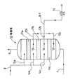
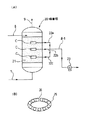
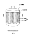
次に、本発明に係る装置の実施形態について、図3〜図6を参照して説明する。なお、図3は、本発明に係る装置の一例を示す吸着塔の縦断面図である。また、図4は、本発明に係る装置の他の例を示す吸着塔であって、図4の(A)は、該吸着塔の断面図であり、同(B)は、同(A)のC部分の拡大詳細図である。さらに、図5および図6は、本発明に係る装置のその他の例を示す吸着塔である。このうち、図5は、該吸着塔の縦断面図であり、図6は、図5の吸着塔を更に説明する図であって、図6の(A)は、図5のA−A線断面図であり、同(B)は、図5の部分拡大詳細図である。
【0053】
本発明に係る装置の一例を示す吸着塔10は、図3に示すように、吸着剤層が独立して11a,11b,11cの3段に分割されて配位され、各吸着剤層11a,11b,11cの下部空間部にそれぞれ排気導管12a,12b,12cを配設し、該排気導管12a,12b,12cを真空ポンプ13に連結した構造からなる。本発明の好ましい実施の形態では、上記吸着剤層11a(最上段の吸着剤層)にMPCを、吸着剤層11bに前記合成ゼオライト(ゼオラム)を、吸着剤層11cに疎水性シリカゲルをそれぞれ配位した構造からなる。なお、図3中、14a,14b,14cは、空気(パージガス)用導管である。また、1は「排ガスの供給ライン」,8は「空気(パージガス)供給ライン」,8−1は「パージ排ガスライン」,9は「大気中に放散するガスライン」を示す。
【0054】
本発明に係る装置の他の例を示す吸着塔20は、図4の(A)に示すように、MPCを充填した吸着剤層21からなる。そして、この吸着剤層21に、図4の(B)で示す“多数の孔25を有するリング24”を埋め込み、このリング24を、排気導管22a,22b,22cを介して、それぞれ真空ポンプ23に連結した構造からなる。(真空ポンプ23は1台として図示したが、これを各排気導管22a,22b,22cに対応して複数台とすることもできる。)なお、図4の(A)中、1は「排ガスの供給ライン」,8は「空気(パージガス)供給ライン」,8−1は「パージ排ガスライン」,9は「大気中に放散するガスライン」を示す。
【0055】
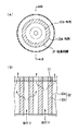
本発明に係る装置のその他の例を示す吸着塔30は、図5および図6(A),(B)に示すように、吸着塔30内の吸着剤層31が複数の通気可能な円筒32(通気可能な外筒32aおよび32bで構成した二重円筒)で囲まれた空間内に吸着剤を充填した構造からなる。そして、排ガスは、図6(B)の矢印線に示すように、吸着剤層31内を通過させるものであり、このように、排ガスの通過面積を広げるように構成したものである。
【0056】
以上、本発明の「清浄なガスとして大気中に放散させるための“揮発性炭化水素含有排ガスの処理”に係る実施の形態」について、主として説明したが、以下に、本発明の「揮発性炭化水素含有排ガスが“不純ガス乃至汚染ガス含有不活性ガス”である場合、該不活性ガスを清浄なガスとして回収するための処理に係る実施の形態」について、図2に基づいて説明する。
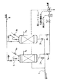
なお、図2は、本発明の一実施形態である“窒素ガス回収システムの概略フローシート図”である。このフローシートは、本発明に基づく大型の商業プラントの運転に係るものであり、窒素ガス(不活性ガス)の存在下に化学反応を行う反応槽から連続的に排出される“汚染窒素”を系外に取り出して再度、循環使用するためのものである。
【0057】
窒素ガス(不活性ガス)の存在下に化学反応を行う反応槽51から、C−1(不純ガス含有窒素ガスライン)を介して、排出される汚染窒素を予めクーラー52で冷却した後、循環圧縮機53で圧縮する。
圧縮された汚染窒素は、水分離器54を経由して、クーラー55で冷やされ、含有している飽和水分の大部分を凝縮して除去する。水分を除去した高圧下の汚染窒素は、フィルター(濾布)56を通すことによって含まれているダストやミストを濾過し、次いで、吸着塔57A(57B)に導く。
【0058】
この吸着塔57A(57B)は、前記した図3または図4に示す吸着塔10または吸着塔20である。吸着剤としては、プレコートしたメソポアー活性炭(MPC)、又は、同様にプレコートした合成ゼオライト及び/又は疎水性シリカゲルと上記メソポアー活性炭(MPC)と併用する。
吸着塔は、交互に切り換えて運転する塔が二基あって、電磁バルブにより、吸着と脱着を交互に切り換える。切り換え時間は1〜30分とし、吸着塔57Aの吸着が完了した時点で、この吸着塔57Aの入口ガス配管の電磁バルブを自動的に“OFF”にして、吸着塔57Bに切り換えて吸着操作を続行する。
【0059】
吸着時に吸着塔57A(57B)から放出される高純度の窒素は、フィルター(活性炭)58で最終的に精製された後、C−2(高純度窒素ガスライン)から、反応槽51に戻し、循環再使用する。
一方、切り換え後の吸着塔57Aは、真空ポンプ59に繋がる配管(図示せず)の電磁バルブ(表示せず)を“ON”にして真空ポンプ59を稼働させ、D−1(パージエアーライン)から、パージ用空気を導入する。真空ポンプ59の排気ガスは、D−2(パージ排エアーライン)を経由して、コンデンサー60に導入する。
【0060】
コンデンサー60で水冷され、分離器61で気液を分離した後、液化した不純ガス乃至汚染ガスをポンプ62で系外に取り出し[D−4(回収液ライン)参照]、未凝縮ガスは、D−3(未凝縮ガスライン)から、廃棄ガスとして処分(処理)する。なお、この未凝縮ガスの処理手段としては、公知の方法に基づいて吸着塔57A(57B)の入口に戻してもよい。
【0061】
以上に詳述したように、本発明は、不活性ガスを再利用するための手段として“吸・脱着操作”を用い、かつ吸着剤層として“プレコートしたメソポアー活性炭(MPC)、又は、該メソポアー活性炭(MPC)とプレコートした合成ゼオライト及び/又は疎水性シリカゲルとを併用する”もので、特に不純ガスを回収することを目的とするものではない。従って、窒素ガスの精製度を上げるべくパージエアーを大量に使用すれば、真空ポンプに負荷がかかって該ポンプが大容量になるので、パージエアーに頼るのではなく、個々の吸着剤内の細孔内の拡散速度を早めることによって、出来るだけ小さい容量の真空ポンプで所望の目的を達成させるための経済効果を含めた新規な不活性ガスの単離方法、および、該方法を実施するための装置を提供するものである。
【0062】
【実施例】
次に、本発明の実施例を挙げ、本発明を具体的に説明するが、本発明は、以下の実施例1〜3によって限定されるものではない。
【0063】
(実施例1:清浄なガスとして大気中に放散させる例)
本実施例1は、図1に示すように、吸着剤を充填した吸着塔(脱着塔)7a,7b、真空ポンプ4、パージ用の空気ライン8,8a,8b、排ガスの供給ライン1、未凝縮ガスの戻しライン6等から成るラボスケールの実験装置を用いて、排ガス中に含まれる揮発性炭化水素を処理する方法の実施に係る例である。
なお、図1中の2a,2b,3a,3b,9,9a,9bは電磁弁、5は気液分離器である。
【0064】
本実施例1において、吸着塔に充填するメソポアー活性炭(MPC)としては、日本ノリツト社製の商品名「GF−40」を用いた。この活性炭の細孔径は、主として20〜30Åのメソポアーからなり、吸着剤の粒径は約3mmであった。また、充填した量は、約1kg(片側)である。
【0065】
本実施例1を図1に基づいて詳細に説明すると、排ガスの供給ライン1から5000PPMのメタノールを含むRH(相対湿度)50%の空気を、毎分20Lの割合で吸着塔7aに送気する。
【0066】
吸着塔7aを操作する前に、まずプレコートさせるための手段として、破過曲線を求めた。その結果を図7に示す。なお、図7は、GF−40(メソポアー活性炭)の破過曲線を示すグラフであって、“D(径)1.3cm,L(長さ)18cmの吸着塔に、前記「GF−40」を6.6g充填し、2L/分の割合でメタノールを吸着させ、吸着終了(各濃度のピーク時)以降は、真空脱着はせず、エアーパージのみで脱着させた”場合をグラフ化したものである。
図7から、5000PPMのメタノールをプレコートするに要する時間は、約200分(3.3時間)であつた。同様にプレコート操作を吸着塔7bについても行い、両方の吸着塔7a,7bが完全にプレコートされたことを確認した後に、前記の排ガスを導入して吸脱着操作を始める。
【0067】
吸・脱着の切り替え時間は5分で、稼働直後は、吸着塔7aの出口ガス中の揮発性炭化水素濃度は4000〜5000PPMであったが、次第に濃度が低くなり、100PPM以下に達するには約2〜3時間要した。また、検証された成果として、前記のプレコート中の発熱は吸着剤層の温度で約60℃であり、実用上まつたく問題のないことが分かった。
【0068】
脱着時に使用した真空ポンプ4は、堀技研工業社製の揺動式ドライタイプであって、到達真空度は15〜25mmHg(3.3Kpa)であり、また、吸引の際にパージガス(空気)を併用した。パージガス(空気)の量は、パージ係数(α)で1.0であった。
真空ポンプ4からのパージ排ガスは、気液分離器5において冷媒(フレオンガス)により0℃〜5℃程度に冷却され、未凝縮のメタノールガスは、戻しライン6を経て、吸着塔の入口の排ガス中に戻される。なお、2a、2bは、吸着塔と脱着塔を5分毎に切り換えるための電磁弁であり、また、9は、同様に清浄な排ガスとして、9a,9bの電磁弁を介して、大気に放散するガスラインである。
【0069】
以上の操作で得られた実験結果は、次の通りである。

上記の実験結果から、メソポアー活性炭は、排ガス中の水分を殆ど吸着せず、そのまま放散ガス中にスルーさせていることが分かった。
このことは、商業規模の大型プラントにおいて、大容量の排ガスを処理する場合、2%前後の水分が“吸着するか,しないか”は大問題であって、もし吸着した場合は、この水分は、脱着時の高真空下で数10倍に体積が膨張するために、脱着に必要な真空ポンプの容量は経済的な許容限度を遙かに超える。しかしながら、MPCの場合には、その障害がないことが判明した。
【0071】
(実施例2:汚染窒素から高純度窒素として回収するための例)
本実施例2は、石油化学工場内の反応層から得られた製品の純度を向上させるために、窒素でバブリング乃至はエアーレーションした後の汚染窒素の回収を目的とする。特に、処理すべきガスがプロパンやプロピレンのような低沸点炭化水素を多量に含む汚染窒素を対象とした例である。
即ち、このガス(汚染窒素)の組成は、以下のとおりである。
N2(窒素) 88%
C3(プロパン) 2%
C3(プロピレン) 5%
C4(ブタン) 1%
C5(ペンタン) 1%
C6以上(ヘキセン等) 3%
【0072】
本実施例2で使用した吸着剤は、メソポアー活性炭(日本ノリット社製の商品名:GF40−45:ペレット)およびB型疎水性シリカゲル(富士シリシア化学社製の商品名:キャリアクトQ−6:10〜20メッシュペレット)である。
【0073】
吸着塔として、図3に示す「吸着塔内の吸着剤層を“独立した吸着剤層”に分離し、該吸着剤層を重ねて配位した吸着塔」を用い、上段に前記メソポアー活性炭を3kg充填し、下段に前記B型疎水性シリカゲルを10kg充填した。
この両吸着剤層のプレコート(ヘキサンを使用したプレアドソープッション)が完了していることを確認した後、上記ガス(汚染窒素)を50L/分の割合で吸着塔の下部から供給し、5分後に脱着操作に切り換えた。即ち、吸・脱着の切り換え時間を5分に設定した。脱着塔の吸引圧力を20torr、パージガス(空気)の量を2L/分とした。これは、パージ係数換算で約1.5である。
以上の条件で運転した結果、得られた回収窒素の純度は、99.9%以上であった。
【0074】
(実施例3:“メタノール/塩化メチレン共吸着”に係る実験例)
吸着塔容量が高さ27cm,径8.5cmの吸脱着装置を用い、この中に吸着剤を“10cm×8.5cm”の高さに充填した。
吸着剤として、日本ノリット社製の商品名「GF−45」(メソポアー活性炭)と富士シリシア化学社製の商品名「キャリアクトQ6」(疎水性シリカゲル)を用い、この両吸着剤を、メタノールと塩化メチレンの混合ガスで予めプレコートした。これを上記吸脱着装置に多層に充填した。順序は、下に“Q6”を充填し、その上に“GF−45”を重ねた。
【0075】
実験条件は、次のとおりである。
即ち、空気と炭化水素(HC)の混合ガスであって、この混合ガス中のメタノール濃度が6.1vol%,塩化メチレン濃度が18vol%であり、関係湿度(RH)が50%であるガスを、以下の条件で処理した。
入口ガス量=1L/分 真空度=15〜25TORR
パージガス量=0.03L/分
【0076】
得られた結果は、出口ガス中のメタノール濃度が“5PPM”、塩化メチレン濃度が“0PPM”であった。この実験により、メソポアー活性炭を用いれば、ほぼゼロエミッションが達成できることを確認した。
【0077】
(比較例:実施例3に対応する比較実験例)
実施例3で用いた吸脱着装置に、吸着剤を変えて、即ち、実施例3と同様にプレコートした富士シリシア化学社製の商品名「キャリアクトQ6」(疎水性シリカゲル)を下部に充填し、その上に同じくプレコートした東ソー社製の商品名「Y型ゼオライト390HUD」を重ねて充填し、実施例3と同様な実験条件で操作した。
得られた結果は、吸着塔の出口ガス中のメタノール濃度が“200PPM”、塩化メチレン濃度が“100PPM”であり、メソポアー活性炭を使用しない比較例(従来法による多層充填方式)では、出口ガス中の炭化水素濃度を100PPM以下にすることが極めて困難であることが分かった。
【0078】
【発明の効果】
本発明は、以上詳記したとおり、「吸・脱着法による揮発性炭化水素含有排ガスの処理方法において、吸着剤層として、前記揮発性炭化水素で予めプレコートして成るメソポアー活性炭(MPC)を充填した層、又は、同様にプレコートして成る疎水性シリカゲル及び/又は合成ゼオライトを前記メソポアー活性炭(MPC)と併用した多層充填層であって、脱着時に真空ポンプとパージガスを併用し、吸・脱着の切り換え時間を1〜30分とし、かつ、得られたパージ排ガスを系外に取り出す」ことを特徴とし、これにより、実質的に揮発性炭化水素成分を含まない清浄なガスとして、大気に放散することができる。
【0079】
また、本発明は、上記「揮発性炭化水素含有排ガス」として、特に、“回収を目的とする有用な成分を含む多成分系炭化水素を含む排ガス”、若しくは、“不純ガス乃至汚染ガス含有不活性ガス”を対象とする場合には、該ガスから、目的成分若しくは不活性ガスを単離・回収し、“高純度成分若しくは高純度不活性ガス”として効率よく再利用を図ることができる。
【0080】
そして、本発明では、吸着剤として、揮発性炭化水素で予めプレコートして成る“メソポアー活性炭(MPC)”を用いることにより、通常の湿度範囲であれば水を選択吸着せず、しかもメタンやエチレン,プロピレンのような極めて低沸点の揮発性炭化水素に対して、他の固体吸着剤には見られない抜群の吸着性能を有するものである。
【図面の簡単な説明】
【図1】本発明の一実施形態である、揮発性炭化水素含有排ガスの処理方法に係るフローシート図である。
【図2】本発明の他の実施形態である、窒素ガス回収システムに係るフローシート図である。
【図3】本発明に係る装置の1例を示す吸着塔の縦断面図である。
【図4】本発明に係る装置の他の例を示す吸着塔の縦断面図である。
【図5】本発明に係る装置のその他の例を示す吸着塔の縦断面図である。
【図6】図5の吸着塔を更に説明する図であって、このうち、(A)は、図5のA−A線断面図であり、(B)は、図5の部分拡大詳細図である。
【図7】GF−40(メソポアー活性炭)の破過曲線を示すグラフである。
【符号の説明】
1 排ガスの供給ライン
2a,2b 電磁弁
3a,3b 電磁弁
4 真空ポンプ
5 気液分離器
6 未凝縮ガスの戻しライン
7a,7b 吸着塔
8,8a,8b 空気(パージガス)供給ライン
8−1 パージ排ガスライン
9 大気に放散するガスライン
9a,9b 電磁弁
C−1 不純ガス含有窒素ガスライン
C−2 高純度窒素ガスライン
D−1 パージエアーライン
D−2 パージ排エアーライン
D−3 未凝縮ガスライン
D−4 回収液ライン
51 反応槽
52 クーラー
53 循環圧縮機
54 水分離器
55 クーラー
56 フイルター(濾布)
57A,57B 吸着塔
58 フイルター(活性炭)
59 真空ポンプ
60 コンデンサー
61 分離器
62 ポンプ
10 吸着塔
11a,11b,11c 吸着剤層
12a,12b,12c 排気導管
13 真空ポンプ
14a,14b,14c 空気(パージガス)用導管
20 吸着塔
21 吸着剤層
22a,22b,22c 排気導管
23 真空ポンプ
24 リング
25 孔
30 吸着塔
31 吸着剤層
32 通気可能な円筒
32a,32b 通気可能な外筒[0001]
TECHNICAL FIELD OF THE INVENTION
The present invention firstly separates volatile hydrocarbons from an exhaust gas containing volatile hydrocarbons by an adsorption / desorption method, takes out the gas as a clean gas from an outlet of an adsorption tower, and disperses the gas into the atmosphere. For treating volatile hydrocarbon-containing exhaust gas and an apparatus for carrying out the method.
[0002]
More specifically, most of the conventional means for removing volatile hydrocarbons in exhaust gas by an adsorption method are known in order to satisfy legally obliged emission concentration regulation values for pollution prevention. (See
The adsorbents used in these known methods are granular activated carbon, fibrous activated carbon, hydrophobic silica gel, and synthetic zeolite. Speaking of activated carbon, although it has been most widely used in the past, it has excellent adsorption performance, but has poor desorption performance, and most of it is heat desorption by steam. Recently, a new activated carbon that can be desorbed only by a purge gas or desorbed only by a vacuum means has been developed. This activated carbon is made based on lignite or peat in China, and in the Netherlands, activated olive seed is activated by phosphoric acid treatment and is commercially available. This has a pore size on the order of nanometers and may be referred to as “nanohole carbon”.
[0003]
The present invention provides a method for treating a volatile hydrocarbon-containing exhaust gas by a novel adsorption method using the above activated carbon which does not require the use of steam for desorption alone or in combination with a widely used hydrophobic silica gel or synthetic zeolite. Device for performing the method ".
Specifically, volatile hydrocarbons such as ethylene, propylene, benzene, toluene, methyl ethyl ketone, trichloroethylene, octadiene, and hexene contained in exhaust gas are subjected to an adsorption treatment to remove the volatile hydrocarbons entrained in the gas. The present invention relates to a method and an apparatus for exhausting at a concentration of preferably 10 ppm or less.
[0004]
Second, the present invention is directed to (1) an exhaust gas containing the volatile hydrocarbon, which is intended to be a "multi-component hydrocarbon gas containing a useful component for the purpose of recovery"; The present invention relates to a method for treating exhaust gas, which is performed for the purpose of separating and recovering only (isolation and recovery), and an apparatus for performing the method.
[0005]
The processing method (1) and an apparatus for performing the method will be described by way of a specific example, “Example of Processing of Exhaust Gas During Production of Synthetic Rubber”.
As a raw material gas used in producing a synthetic rubber, butyl rubber, butadiene rubber, or ethylene is obtained by polymerizing a wide variety of olefin-based hydrocarbons, such as ethylene, propylene, or butadiene, alone or in combination. -It is well known that products such as propylene rubber are obtained, but in the exhaust gas generated during such a polymerization reaction, there are gases that can be discarded (by-product gases) and gases to be recovered (unreacted gases). Coexist. For example, in certain polymerization reaction systems, ethylene and butene coexist in the exhaust gas. At this time, what is desired to be collected and reused is unreacted ethylene gas, what is desired to be discarded is by-product butene gas, and the unreacted ethylene to be reused is recovered with a purity of 99.9% or more. There is a need. However, in the prior art, there is no technology for separating and recovering a gaseous state without liquefaction, so that it is incinerated at present.
The present invention is directed to a multi-component hydrocarbon gas containing a useful component such as the above-mentioned unreacted ethylene, which is used for the purpose of separating and recovering only a useful component from the gas with high purity (isolation and recovery). The invention relates to a processing method and an apparatus for implementing the method.
[0006]
(2) As the exhaust gas containing volatile hydrocarbons, “inert gas containing volatile hydrocarbon impurity gas or pollutant gas” is targeted, and is absorbed and desorbed from the impurity gas or pollutant gas-containing inert gas. Of volatile hydrocarbon-containing exhaust gas (volatile hydrocarbon impurity gas or pollutant gas-containing inert gas) for separating volatile hydrocarbons by the method and recovering them from the outlet of the adsorption tower as a clean inert gas. The invention relates to a processing method and an apparatus for implementing the method.
[0007]
The treatment method of (2) and the apparatus for carrying out the method will be described in detail. The method is such that a reaction is performed in the presence of an inert gas or a product is treated with an inert gas (for example, nitrogen gas). Impurity gas or pollutant gas (volatile reactant or unreacted raw material, or impurity gas or pollutant gas such as reaction product) accompanying cleaning, for example, ethylene, propylene, benzene, toluene, methyl ethyl ketone, trichloroethylene The present invention relates to a process for purifying an inert gas containing a volatile impurity gas or a pollutant gas such as octadiene, octadiene, hexene, etc., wherein the component concentration of the impurity gas or the pollutant gas entrained in the inert gas is 100 ppm or less, preferably 10 ppm. In the following, in other words, the purity of the inert gas is set to 99% or more as desired, and Law and apparatus. As used herein, the term "inert gas" refers to nitrogen, carbon dioxide, helium, xenon, chlorofluorocarbon, or the like, and collectively refers to chemical substances that have extremely low activity alone.
[0008]
[Prior art]
It is said that there are 20,000 kinds of chemical products currently used in Japan, and most of them are made in chemical factories, petrochemical factories, pharmaceutical factories and the like. The gas discharged directly from the manufacturing process to the outside contains various volatile hydrocarbons as described above. Also, the product obtained in the above process is mixed with air at the time of storage, transportation, unloading and unloading, and is similarly released into the atmosphere.
[0009]
On the other hand, most of the above chemical products use basic organic chemicals such as aromatic, aliphatic, heterocyclic, and organic halogen as basic materials and react them under a catalyst to produce the desired product. Have gained.
In the reaction step at this time, the reaction often proceeds in the presence of an inert gas such as nitrogen, carbon dioxide, carbon monoxide, and helium. In such a case, after the reaction is completed, the used inert gas is contaminated by the reaction product and cannot be reused, and the present situation is that the inert gas is usually disposed of as it is. Further, even in a semiconductor manufacturing plant or the like, many etching agents (for example, ruthenium dioctadiene) used for etching are composed of gas components which are difficult to dispose similarly to the above. Alternatively, there is a case where an undesired impurity gas is separated from a reaction system gas generated in a reaction process of a petrochemical process to obtain a target component with high purity.
[0010]
By the way, if the exhaust gas contaminated with volatile hydrocarbons (including “contaminated inert gas”; the same applies hereinafter) is directly emitted into the atmosphere, it becomes one of the main pollutants of air pollution as impurity gas or polluted gas. However, harmful gases such as benzene, toluene, methylene chloride, methyl ethyl ketone, trichloroethylene, and chlorofluorocarbon are entrained, violating legal regulations on emission concentrations. For this reason, at present, each of the above-mentioned factories has a difficulty in treating the exhaust gas.
[0011]
Conventionally, as a method for treating such exhaust gas, this gas containing impurities or contaminant gas is washed with water, or washed with an acid or alkali, and then washed with a high boiling point sponge oil (for example, heavy oil). After the mixed impurity gas is adsorbed using activated carbon of a type, the activated carbon is taken out and treated for industrial waste before breakthrough.
In addition, if the exhaust gas contains a polymerization component such as a diene as a mixed pollutant gas, conventional activated carbon cannot be used.In such a case, the emission concentration is set to be equal to or less than the emission concentration specified in the regulations of each local government. The pollutant gas was diluted in the air, and although it was a palliative measure, it was released to the atmosphere as it was.
[0012]
However, when steam is used for water washing, acid or alkali washing or heavy oil washing, and also for regeneration of conventional activated carbon, wastewater treatment equipment is indispensable.
Even when treated with activated sludge, the BOD value passes the drainage standard, but a large amount of aeration is required because the COD value does not decrease. In this case, the impurity gas or the contaminated gas released into the wastewater and mixed into the water is re-emitted into the atmosphere together with the aeration. Although this concentration depends on the amount of aeration, it is usually relatively thin, less than 100 ppm, and satisfies the "emission concentration regulation value of 250 ppm or less (in the case of Tokyo)" defined by the conventional local government. Did not occur.
[0013]
However, the law enacted after April 2002 (April 2002), entitled "Act on the Estimation and Management of Emissions of Specific Chemical Substances into the Environment", the so-called "PRTR Law" This is not the emission concentration regulation that has been conventionally practiced, but the emission regulation of the entire factory. As described above, it becomes impossible to reduce the amount of air discharged into a large amount during aeration.
In view of such a situation, the present inventors have processed exhaust gas containing volatile hydrocarbons using a novel adsorbent different from before, and have found that alcohols, aromatics, paraffins, and olefins mixed in the exhaust gas have been treated. The present invention has been completed from a “pollution prevention point of view” of achieving zero emission by removing various kinds. Further, the present inventors, as the volatile hydrocarbon-containing exhaust gas, target "multi-component hydrocarbon gas containing a useful component for the purpose of recovery" or "impurity gas or pollutant gas-containing inert gas" The present invention has been completed from the viewpoint of "useful components" or "inert gas" from the gas in terms of "separation, recovery and reuse".
[0014]
As means for achieving the above-mentioned objects, volatile hydrocarbons contained in exhaust gas are gasoline vapor, water-soluble alcohols, polymerizable olefin gas, and the like. Because of the variety, the selection of the adsorbent requires great care.
[0015]
By the way, as a method for separating contaminants in exhaust gas for the above-mentioned purpose, techniques such as cryogenic separation, distillation, absorption and the like have been conventionally used.
Further, regarding the adsorption separation method, known methods widely used in the field include:
(1) Gas separation membrane method + adsorption method
(2) Adsorption method using activated carbon, zeolite, hydrophobic silica gel, etc.
And so on. For example, it is described in detail in Patent Documents 6 to 9 in addition to
[0016]
Such an adsorption method includes a conventional means for switching between adsorption and desorption, and although not particularly novel, the polluting components contained in the exhaust gas include components such as methane and ethane having a very low boiling point, such as pentane and hexane. In the case where the adsorbent widely covers components having a relatively high boiling point, it is difficult to cope with only a single adsorbent having functional restrictions as the adsorbent to be used.
For example, in the case of using a conventionally used activated carbon as an example, if the mixed pollutant gas (contaminant component) is a diene, an olefin or the like, it is inspired by a large number of active points present in the activated carbon. Such compounds are easily polymerized, and there is a danger of ignition and explosion due to the heat of polymerization, so that their use has been legally prohibited.
[0017]
[Patent Document 1]
JP-A-9-47635
[Patent Document 2]
JP-A-9-57060
[Patent Document 3]
JP-A-9-215908
[Patent Document 4]
JP-A-11-71584
[Patent Document 5]
JP-A-11-77495
[Patent Document 6]
JP-A-57-14687
[Patent Document 7]
JP-A-57-42319
[Patent Document 8]
JP-B-59-50715
[Patent Document 9]
JP-B-59-50716
[0018]
[Problems to be solved by the invention]
The present invention has been made in view of the above problems, and has as its object (problem), first, a flame-retardant activated carbon whose pore diameter is mainly composed of mesopores (about 20 to 40 °). (Hereinafter referred to as “MPC”) alone or in combination with hydrophobic silica gel and / or synthetic zeolite pre-coated in the same manner to remove volatile hydrocarbons mixed in the exhaust gas to obtain zero emissions. Another object of the present invention is to provide a "treatment method for separating hydrocarbons from an exhaust gas containing volatile hydrocarbons and an apparatus for carrying out the method" which achieves the above-mentioned method (→ first object).
[0019]
Secondly, the present invention provides, as in the first case, an adsorbing means by using alone or in combination with hydrophobic silica gel and / or synthetic zeolite similarly precoated with MPC. Applied,
(1) As an exhaust gas containing volatile hydrocarbons, “containing useful components for the purpose of recovery”
Multi-component hydrocarbon gas, and isolate and recover only the target component from the gas
Collected and reused as “high-purity components”, that is, to recover.
Efficiently improve "target components" in multi-component hydrocarbon gas containing useful components
Separate
(2) As an exhaust gas containing volatile hydrocarbons, “inactive containing impurity gas or pollutant gas”
Inert gas is isolated and recovered from the target gas, which is referred to as "high-purity inert gas".
To reuse as "active gas", that is, including impure gas or pollutant gas
Efficient separation of "impurity gas or pollutant gas" in inert gas
It is an object of the present invention to provide a "treatment method for separating hydrocarbons from an exhaust gas containing volatile hydrocarbons and an apparatus for performing the method" (→ second object).
[0020]
[Means for Solving the Problems]
The treatment method according to the present invention for separating volatile hydrocarbons (contaminant gas) contained in exhaust gas by an adsorption method has a technical configuration to achieve the first and second objects (problems) described above. A layer filled solely with MPC precoated with the contaminant gas as the adsorbent layer, or similarly precontaminated with a contaminant gas. A multi-layer packed layer using the synthetic zeolite and / or hydrophobic silica gel and MPC in combination, wherein the adsorbent layer is allowed to pass an exhaust gas containing a contaminated gas to adsorb the contaminated components, and It is extracted as a clean gas that does not contain polluting components.
[0021]
That is, the method for treating volatile hydrocarbon-containing exhaust gas according to the present invention includes:
・ One adsorption using “adsorption device with adsorbent layer” that alternately performs adsorption and desorption
The exhaust gas containing volatile hydrocarbons is passed through the device, and the adsorbent layer in the adsorption device
Adsorbs volatile hydrocarbons and removes exhaust gas substantially free of volatile hydrocarbons.
Take out from the outlet of the adsorption device, and switch the other adsorption device to desorption during that time
To remove volatile hydrocarbons previously adsorbed out of the system
In the method for treating hydrogen fluoride-containing exhaust gas,
The adsorbent layer is filled with MPC pre-coated with the volatile hydrocarbon.
A packed or otherwise pre-coated hydrophobic silica gel and
And / or a multi-layer packed layer using a synthetic zeolite in combination with the MPC,
A vacuum pump and purge gas are used together, and the switching time between suction and desorption is 1 to 30 minutes
And the obtained purge exhaust gas is taken out of the system (claim 1).
Thus, the first and second objects can be achieved.
The “mesopore activated carbon (MPC)” used in the present invention means “flame-retardant activated carbon composed of mesopore pores whose pore size is mainly on the order of nanometers”.
[0022]
Further, in the present invention, the "exhaust gas containing volatile hydrocarbons" includes "a multi-component hydrocarbon gas containing a useful component for the purpose of recovery" or "an inert gas containing an impure gas or a pollutant gas". The present invention also includes the case where the object is set forth (
[0023]
Further, a method for treating volatile hydrocarbon-containing exhaust gas according to the present invention (a method for separating volatile hydrocarbons from exhaust gas and purifying it as a clean gas, or extracting a target component gas or an inert gas). Is
・ The purged exhaust gas is cooled, and the uncondensed gas at this time is introduced into the adsorber at the inlet.
(Claim 4),
・ Pressurization or “exhaust gas containing volatile hydrocarbons” to be introduced into the adsorption device
After a cooling process in advance, an adsorption process is performed (claim 5).
It is characterized by the following.
[0024]
On the other hand, an apparatus according to the present invention is an apparatus for performing the processing method according to any one of
・ A plurality of independent solid adsorbent layers with different adsorption characteristics in the adsorbent layer in the adsorption device
And has a structure in which the plurality of independent adsorbent layers are superposed and coordinated.
That (claim 6),
・ Each exhaust pipe is buried between multiple independent solid adsorbent layers in the adsorber.
And a structure for connecting the conduit to a vacuum pump (claim 7).
・ The adsorbent layer in the adsorption device is filled in a space surrounded by a plurality of permeable cylinders.
Having a structure (claim 8),
It is characterized by.
[0025]
[Embodiment of the present invention]
Hereinafter, embodiments of the present invention will be described. Prior to this, the present invention will be described in more detail.
[0026]
The activated carbon used in the conventionally known “adsorption method using activated carbon” has a myriad of pores formed of micropores, and volatile hydrocarbons in exhaust gas that have penetrated deeply into the pores and diffused, and activated carbon. The carbon wall, which is a component of the above, forms a strong C--C bond due to strong van der Waals force, but has a strong affinity. It generates heat and there is a risk of fire for easy use.
It is also known that a heating means such as steam is required in order to release volatile hydrocarbons causing capillary condensation from the micropores, and it is not desorbed by simple means such as a vacuum pump or a purge. . Further, when volatile hydrocarbons (contaminant gas; contaminant components) are diene compounds, olefins and the like, the active components existing in the activated carbon are inspired by a large number of active sites, and such components readily polymerize. As described above, heat is accompanied by danger of ignition and explosion.
[0027]
In order to solve the above problem, the present inventors have proposed a flame-retardant activated carbon consisting of mesopore pores whose pore size is mainly on the order of nanometers, instead of the above-mentioned activated carbon that has been conventionally widely used. (MPC) or a well-known non-combustible solid adsorbent, specifically, a synthetic zeolite and / or hydrophobic silica gel is used in combination with MPC, and the active sites present in the pores of these adsorbents are further determined. It has been found that the above-mentioned danger associated with the adsorption of volatile hydrocarbons can be avoided by pre-blocking using a precoating means.
[0028]
Generally, the pores of the adsorbent are formed from three micropores, mesopores, and macropores. The average of the micropores is about 3 to 10 °, the mesopores are about 20 to 60 °, and the macropores are about 60 to 100 °. The mechanism for adsorbing volatile hydrocarbons and moisture depends on the diameter of each pore.
That is, adsorption to micropores is surface diffusion, and adsorption to mesopores is pore diffusion. Macropores are vents for the molecules to enter and exit, regardless of their mechanism. For example, in a normal activated carbon, the surface area of the micropores is 1000 to 2000 m per gram. 2 In contrast, hydrophobic silica gel is mainly composed of mesopores, and the surface area of the mesopores is 400 to 600 m per gram. 2 It is.
[0029]
In short, a huge amount of energy is required for the above molecules to enter micropores and mesopores, especially micropores. Generally, the heat of adsorption is about 1.5 times the latent heat of vaporization. It is said that there is a fever. This heat is caused by the capillary condensation of volatile hydrocarbons (HC) in the above-mentioned micropores. When the hydrocarbons become mesopores, capillary condensation hardly occurs, and as described above, the surface area inside the pores is reduced. It has been experimentally confirmed that the small size does not cause the temperature to rise to dangerous levels.
This means that in the case of desorption, there is a possibility that hydrocarbons (HC) can be desorbed from the inside of the pores only by suctioning with a normal temperature purge gas or a vacuum pump without heating.
[0030]
Focusing on the properties of such an agent, in order to easily and desorb HC from within the pores of the MPC in a short time, a precoat (preadsorption) of an adsorbent conventionally proposed by the present inventors has been proposed. The reason why this is a very important adsorption / desorption means will be described in detail below.
That is, if volatile hydrocarbon (HC) as an adsorbent component is not present in the pores in advance in the adsorbed particles, the diffusion rate of HC entering holes in the virgin adsorbed particles is not so fast. In particular, 1000m 2 The diffusion rate (penetration rate) into the pores having a surface area of / g or more depends on the concentration of HC in the supply gas, but takes about several seconds to several tens of seconds. Of course, the type of adsorbent is also very relevant.
[0031]
In short, whether "surface diffusion" or "pore diffusion", the speed of sliding into the pores or the speed of condensation (liquefaction) in the capillary, if the pressure is normal pressure, the concentration and the contact time As a function, it does not penetrate so deep into the pores. As the flowing gas comes into contact with the adsorbent many times, the air occupying the hole is eliminated, and the gas gradually enters the hole. In the case of using activated carbon with micropores controlled by micropores, heating is necessary for desorption of HC adsorbed in this way, usually it is driven out entirely with steam, and then the attached moisture is dried and emptied Since the adsorption is started again, considerable time is required for the adsorption and desorption.
[0032]
In extreme terms, the HC in the inlet gas is so fast that it passes through the adsorbent surface before exiting the pores and exits the outlet of the adsorption tower.
That is, when the pre-coating was not performed through a predetermined procedure, the outlet gas concentration of the adsorption tower was changed to the inlet gas concentration as shown in the experimental results when the present inventors used hydrophobic silica gel as the adsorbent. While the concentration of HC (methyl alcohol) in the gas is about 5000 PPM, the concentration of HC in the outlet gas is abnormally high at 1200 PPM. This is not the result of the imbalance between the rising speed of HC contained in the inlet gas and the adsorbing speed of HC trying to enter the pores of the adsorbent. To adsorb, the capillary must be condensed. In other words, if the inside of the pores is pre-coated with HC prior to adsorption, neither the water nor the HC in the exhaust gas will be capillary-condensed in the pores.
[0033]
As has been done by conventional researchers and others, if the position of emphasizing the speed of entry into empty pores and trying to speed it up is to increase the HC concentration in the exhaust gas, There is no choice but to reduce the speed, that is, to increase the contact time or to pressurize. Alternatively, an adsorbent having a large number of micropores capable of accommodating HC, that is, having as large an adsorption surface area per gram as possible must be used.
[0034]
The inventors of the present invention did not increase the rate of intrusion (diffusion) into such pores. Instead, the present inventors have studied the affinity between HC precoated on the surface of the adsorbent and HC in exhaust gas ascending the adsorption tower. I have been conducting research with emphasis.
The reason is that activated carbon composed of micropores cannot treat exhaust gas containing HC concentration of 1% or more due to legal regulations, and it is customary to use steam for desorption. Therefore, in order to take the procedure of taking out all the HC slid into the micropore out of the system, making it empty without moisture, and then returning to adsorption, the switching time between adsorption and desorption is a long swing of "1 to 6 hours". Was needed.
[0035]
In order to solve the above-mentioned drawbacks, it is also conceivable that the inventors of the present invention have tried a pre-coating method which has been proposed for a long time.In particular, in treating an exhaust gas containing rich HC, a pre-coat of activated carbon composed of micropores is required. Although it is extremely dangerous work, and rarely, in some commercial plants, pre-coating is gradually performed in a nitrogen stream for about 12 hours in view of an unexpected accident in the past. Thus, in order to avoid the danger of heat of adsorption accompanying capillary condensation, the present inventors did not follow the “equilibrium model” or “frozen model” that has been studied and proposed, but instead used surface diffusion. Of adsorption dimensions such as diffusion and pore diffusion, "at the time of adsorption, the dissolution phenomenon between HC (condensate) previously filled in pores and HC in exhaust gas rising in the adsorption tower", "Desorption Time is due to the evaporation of HC from the condensate filled in the adsorbent. " In short, it is a "pre-coat model" proposed by the present inventors. In this model, for the desorption step, surface diffusion is dominated by purge and pore diffusion is dominated by vacuum.
[0036]
As shown by this “pre-coat model”, if the mass transfer phenomenon in the pores is not mainly caused by the mechanism of surface diffusion or pore diffusion, but if the dissolution and evaporation phenomena are dominant, the adsorption rate The physical property value required as a factor that governs not the overall mass transfer coefficient (Kfav) but the value of the mass transfer coefficient (diffusion coefficient) of each HC molecule moving through the surface of each adsorbent particle. Since benzene, pentane, and the like have individual values, it is necessary to construct a database.
In this model, unlike the known equilibrium model or frozen model, the HC pre-coated as described above must be kept in the particles as much as possible. This layer should not be scraped or peeled off more than necessary. For this purpose, it is important not to apply too much purging or apply too much vacuum. Ideally, however, HC that is sufficient for the HC in the exhaust gas dissolved in the precoated HC (condensate) is removed by vacuum. Or by means of purge means.
[0037]
However, in the actual device, the amount of HC pre-coated in the adsorbent layer cannot be controlled as desired, so that the depth of the hole removed by purging or vacuuming, or the amount of HC stacked in the hole is reduced. This is the reason why uncondensed gas in the purge exhaust gas is returned to the source gas in order to restore the original thickness.
[0038]
As another alternative, a part of the concentrated HC gas contained in the purge exhaust gas obtained at the time of desorption is used as a purge gas, and the air and moisture in the desorption tower are purged and replaced with HC gas. This is a method of performing a so-called “reflux concentration operation (substitution purge)”. This method is an effective means for selectively adsorbing only alcohol to the adsorbent when HC in the exhaust gas is alcohol soluble in water.
[0039]
On the other hand, if "excessive desorption" is to be said, since there is no HC in the empty portion as described above, HC in the rising gas passing therethrough is attracted into the pores. Since the affinity, that is, the dissolving power does not work, the adsorption depends exclusively on the diffusion rate of the HC molecules into the pores.If the rate of the rising gas is high, the HC molecules in the feed gas will be adsorbed. The particles pass through the surface of the agent particles and exit from the outlet of the adsorption tower. In both the experiment and the actual apparatus, when the swing of “5 minutes-5 minutes” and the swing of “15 minutes-15 minutes” are compared, the latter “15 minute-15 minute” swing is clearly worse. Of course, if the speed is made extremely slow, it does not mean that it is impossible to penetrate into the particles according to the diffusion speed into the pores and the contact time, but with the actual device actually made, Apart from that, it is optimally designed for a given material balance, so that no major changes in the operating manual are allowed.
In short, the switching of “5 minutes to 5 minutes” means that the amount of HC that can be accommodated in the pores is limited as long as the mesopore region in the adsorbent particles after the pores in the adsorbent are filled with HC in advance. This is the maximum time to fill. This limit is at most about 10 minutes.
[0040]
In summary, the theoretical pillar of the present invention is:
(1) Pre-coating of adsorbent (pre-adsorption),
(2) return of uncondensed gas,
(3) Quick swing when switching between adsorption and desorption,
This has already been proposed by the present inventors, for example, in Patent Document 1 (JP-A-9-47635) and Patent Document 4 (JP-A-11-71584). Described and known.
However, the above-mentioned
[0041]
As described above, the mass transfer phenomenon of HC through the pores on the surface of the adsorbent particles can be said to be reduced to a simple model of condensation and evaporation of HC molecules.
As described above, in the present invention, adsorption and desorption rely only on mass transfer between HC (condensate) filling the mesopore pores of the adsorbent and HC (gas) in exhaust gas. Of course, there is a limit to the capacity to contain HC. Therefore, the time for switching between suction and desorption is inevitably shortened. Generally, the shorter the time, the better, but it is limited by the service life of the solenoid valve, and the lower limit is “about 1 minute”. On the other hand, regarding the upper limit value, if the time is extended, an enormous amount of the adsorbent is required. Therefore, the present inventors have limited the time to “about 30 minutes” for economical considerations.
[0042]
Hereinafter, a preferred embodiment of the present invention will be described.In the operation of switching between adsorption and desorption, it is extremely preferable to keep the volatile hydrocarbon-containing exhaust gas introduced into the adsorption device in a pressurized state during adsorption, Cooling the exhaust gas is also preferable because it has the effect of condensing moisture contained in the exhaust gas.
On the other hand, it is also preferable to heat the purge gas at the time of desorption, and it is preferable to use air and / or nitrogen as the purge gas or to use a part of the purge exhaust gas again as the purge gas. It is also preferable to dehumidify the purge gas (air and / or nitrogen) at the time of desorption. The advantage of dehumidifying the purge gas is that the moisture contained in the purge gas under normal pressure expands about 30 times when the vacuum pump is operated at 25 TORR, so that the vacuum pump maintains a predetermined 25 TORR. Lost. Therefore, by removing water, (a) reducing the load on the vacuum pump used for regeneration, and (b) preventing capillary condensation of water that enters the adsorbent layer during desorption in advance. Two points.
[0043]
The use of a part of the concentrated volatile hydrocarbons in the purge exhaust gas as the purge gas is to sweep out water or air condensed in the capillary and replace it with a pre-coated state, that is, it is called "replacement purge or reflux concentration". Although it is a known means, in the present invention, a remarkable effect can be obtained by using it in combination with mesopore activated carbon (MPC).
[0044]
It is also a preferred embodiment of the present invention to return the uncondensed gas after cooling the purge exhaust gas to the inlet of the adsorption device or directly to the adsorbent layer.
That is, when the concentration of the uncondensed gas is lower than the inlet gas of the adsorption device, if this gas is returned and mixed with the inlet gas, the concentration of the inlet gas may be unnecessarily reduced. Therefore, it is separated from the denser inlet gas and introduced from the bottom of the adsorption tower, while the inlet gas is supplied to the adsorbent layer from the middle part of the adsorption tower. In the opposite case, that is, when the concentration of the uncondensed gas is higher than that of the inlet gas, the gas may be mixed with the gas, but desirably, the uncondensed gas is directly returned to the intermediate portion of the adsorbent layer. good. As a result, the hydrocarbon concentration in the purge exhaust gas is significantly increased. This means is particularly effective in the case of very low-temperature (for example, 0 ° C. or lower) highly volatile hydrocarbon or chlorofluorocarbon gas. Usually, when the adsorption is at normal pressure and the desorption is at a reduced pressure of 25 mmHG, the enrichment does not exceed about 30 times.
[0045]
Further, a preferred embodiment of the present invention is that the exhaust gas containing volatile hydrocarbons to be introduced into the adsorption device is subjected to an adsorption treatment after being treated with an absorbing liquid or washing water in advance or after being pressurized.
[0046]
At the time of adsorption, it is known to use an adsorbent layer filled with a solid adsorbent, and at the time of desorption, it is known to use a vacuum pump together with a purge gas. In particular, one selected from among the above is a vacuum-desorbable mesopore activated carbon (MPC). In one embodiment, the adsorbent layer in the adsorption device is
(A) separating into a plurality of independent adsorbent layers having different adsorption characteristics, and
To have a structure in which the adsorbent layers are stacked and coordinated (in this case, each adsorbent
Preferably, an exhaust conduit is embedded between the layers and the conduit is connected to a vacuum pump).
(B) filling the adsorbent in the adsorption device into a space surrounded by a plurality of gas-permeable cylinders;
To make the flow direction of the waste gas a radiant flow,
, Thousands, tens of thousands of meters per hour 3 Large amount of gas can be processed, and a remarkable adsorption / desorption effect that could not be found by the conventional method was successfully obtained.
[0047]
As the adsorbent used in the present invention, a layer in which activated carbon (MPC) whose adsorption pore size is mainly composed of mesopores is packed in a single layer, or a synthetic zeolite and / or hydrophobic silica gel is used as the activated carbon (MPC) It is a multilayer filling layer used in combination, and in any case, it is used in a pre-coated state.
As the precoating agent, it is preferable to use the same type of component gas as the pollutant gas in the "exhaust gas containing a pollutant gas (volatile hydrocarbon)" which is the gas to be treated.
[0048]
As a preferred embodiment of the solid adsorbent used in the present invention, when the volatile hydrocarbons contained in the exhaust gas is only gasoline vapor or only aromatics such as benzene and toluene, the mesopore An adsorbent layer composed of a single layer of activated carbon (MPC) may be used, but the hydrocarbons to be removed are very low-boiling gas such as methane, ethylene and propylene, and relatively low-boiling gas such as pentane, hexene and benzene. In the case of treating an exhaust gas in which a gas having a high boiling point is mixed, it is preferable to use a synthetic zeolite and / or hydrophobic silica gel in combination with MPC and stack the layers in multiple layers. At that time, great care is needed in selecting the adsorbent.
[0049]
As a specific example, when the volatile hydrocarbons contained in the exhaust gas are limited to low-boiling compounds such as methane and ethylene, a single layer of MPC is used, and high-boiling hydrocarbons or low-boiling hydrocarbons are used. When coexisting with a hydrocarbon, MPC, a Y-type synthetic zeolite having a high silica ratio or a synthetic zeolite having a high alumina ratio (trade name: Zeolam, manufactured by Toso Corporation), A-type hydrophobic silica gel and / or B-type hydrophobic Use silica gel. Then, the MPC is coordinated at the uppermost stage, and then the synthetic zeolite (zeolam), the A-type hydrophobic silica gel, and / or the B-type hydrophobic silica gel are coordinated in this order.
The reason is that the adsorption pore size of MPC is 20 to 40 °, the pore size of A type hydrophobic silica gel is 30 °, and the pore size of B type hydrophobic silica gel is 60 °. By the way, it is based on the fact that when the relative pressure is low, such as methane, ethylene and propylene, the MPC and the A-type hydrophobic silica gel (30 °) have a larger adsorption amount. On the other hand, B-type hydrophobic silica gel (average pore diameter: 60 °) is easier to adsorb and desorb high-boiling hydrocarbon gases such as pentane, hexane and benzene. Further, the above-mentioned MPC and synthetic zeolite (zeolam) are hydrophilic, but have the property of selectively adsorbing low-boiling methane and ethylene in the absence of water.
[0050]
The reason that it is preferable to coordinate the MPC at the uppermost stage is that ordinary activated carbon causes capillary condensation of water at about 40% RH (relative humidity), whereas MPC has a capillary condensation of about 60% RH. It does not selectively adsorb water in the normal humidity range, and is unlike other solid adsorbents for extremely low boiling volatile hydrocarbons such as methane, ethylene and propylene. This is because it has excellent adsorption performance that cannot be achieved.
[0051]
The adsorption / desorption method in the present invention aims at (1) discharging gaseous hydrocarbons in the air, which have been widely used in the past, to legally regulated values or less. Also, (2-1) recovering a high-purity useful component from a multi-component hydrocarbon gas containing a useful component for the purpose of recovery, (2-2) producing a polymer such as polypropylene, for example. The purpose is to recover high-purity inert gas (nitrogen gas) from the polluted gas (pollutant nitrogen gas containing volatile hydrocarbons) that is discarded in the process. This is one of the unit operations similar to the distillation operation and the absorption operation which are also applied to the means of purification, and as described above, the target component is simply subjected to the adsorption operation from the multi-component gas mixed in the exhaust gas. It is no exaggeration to say that this is a new separation technique of separating or contaminating an inert gas from the contaminated gas.
However, if each technique is taken up individually, it belongs to a known technique, but newly uses mesopore activated carbon (MPC), or is combined with a known hydrophobic silica gel or synthetic zeolite to fill a multilayer. It has been found that the use of a novel method, such as that described above, achieves a significantly superior effect as a method for treating volatile hydrocarbons in exhaust gas as compared with cryogenic separation, chemical solution cleaning, or treatment with an absorbing solution. It is a thing.
[0052]
Next, an embodiment of the device according to the present invention will be described with reference to FIGS. FIG. 3 is a longitudinal sectional view of an adsorption tower showing an example of the apparatus according to the present invention. FIG. 4 is an adsorption tower showing another example of the apparatus according to the present invention. FIG. 4 (A) is a sectional view of the adsorption tower, and FIG. It is an enlarged detail view of C part of FIG. FIGS. 5 and 6 show an adsorption tower showing another example of the apparatus according to the present invention. 5 is a longitudinal sectional view of the adsorption tower, FIG. 6 is a diagram further illustrating the adsorption tower of FIG. 5, and FIG. 6 (A) is a line AA of FIG. It is sectional drawing, (B) is the elements on larger scale detail drawing of FIG.
[0053]
As shown in FIG. 3, in an adsorption tower 10 which is an example of the apparatus according to the present invention, the adsorbent layers are independently divided and arranged in three stages of 11a, 11b, and 11c, and each
[0054]
An adsorption tower 20 showing another example of the apparatus according to the present invention includes, as shown in FIG. 4A, an
[0055]
As shown in FIGS. 5 and 6 (A) and (B), an adsorption tower 30 showing another example of the apparatus according to the present invention has an
[0056]
As described above, the “embodiment relating to“ treatment of exhaust gas containing volatile hydrocarbons for emission into the atmosphere as a clean gas ”” of the present invention has been mainly described. An embodiment of a process for recovering an inert gas as a clean gas when the hydrogen-containing exhaust gas is an "impurity gas or a pollutant gas-containing inert gas" will be described with reference to FIG.
FIG. 2 is a schematic flow sheet diagram of a nitrogen gas recovery system according to an embodiment of the present invention. This flow sheet relates to the operation of a large-scale commercial plant based on the present invention, and is used to remove “contaminated nitrogen” continuously discharged from a reaction tank that performs a chemical reaction in the presence of nitrogen gas (inert gas). It is intended to be taken out of the system and reused again.
[0057]
The contaminated nitrogen discharged from the
The compressed contaminated nitrogen is cooled by a cooler 55 via a
[0058]
The
The adsorption tower has two towers that operate alternately and alternately switches between adsorption and desorption by an electromagnetic valve. The switching time is 1 to 30 minutes. When the adsorption of the
[0059]
High-purity nitrogen released from the
On the other hand, in the
[0060]
After being water-cooled by the
[0061]
As described in detail above, the present invention uses "absorption / desorption operation" as a means for recycling inert gas, and uses "precoated mesopore activated carbon (MPC)" or "mesopore activated carbon" as an adsorbent layer. Activated carbon (MPC) is used in combination with pre-coated synthetic zeolite and / or hydrophobic silica gel, and is not intended to recover impure gases. Therefore, if a large amount of purge air is used in order to increase the purity of nitrogen gas, a load is applied to the vacuum pump and the pump becomes large in capacity. A novel method for isolating inert gases, including the economic effect of achieving the desired objective with a vacuum pump having the smallest possible volume by increasing the diffusion rate in the pores, and a method for performing the method. An apparatus is provided.
[0062]
【Example】
Next, the present invention will be described in detail with reference to Examples of the present invention. However, the present invention is not limited to Examples 1 to 3 below.
[0063]
(Example 1: Example of emission into the atmosphere as a clean gas)
In the first embodiment, as shown in FIG. 1, adsorption towers (desorption towers) 7a and 7b filled with an adsorbent, a
In FIG. 1, 2a, 2b, 3a, 3b, 9, 9a, 9b are solenoid valves, and 5 is a gas-liquid separator.
[0064]
In Example 1, as the mesopore activated carbon (MPC) to be filled in the adsorption tower, "GF-40" (trade name, manufactured by NORIT CORPORATION, Japan) was used. The activated carbon had mainly 20 to 30 ° mesopores, and the adsorbent had a particle size of about 3 mm. In addition, the filled amount is about 1 kg (one side).
[0065]
The first embodiment will be described in detail with reference to FIG. 1. The 50% RH (relative humidity) air containing 5000 PPM methanol is sent from the exhaust
[0066]
Before operating the
From FIG. 7, the time required for pre-coating with 5000 PPM methanol was about 200 minutes (3.3 hours). Similarly, a precoating operation is performed on the
[0067]
The switching time between adsorption and desorption is 5 minutes. Immediately after the operation, the concentration of volatile hydrocarbons in the outlet gas of the
[0068]
The
The purge exhaust gas from the
[0069]
The experimental results obtained by the above operation are as follows.
From the above experimental results, it was found that the mesopore activated carbon hardly adsorbs the moisture in the exhaust gas and passes through the gas as it is.
This means that when a large-scale exhaust gas is treated in a large-scale commercial-scale plant, about 2% of the water is "adsorbed or not adsorbed". Because the volume expands several tens of times under a high vacuum during desorption, the capacity of the vacuum pump required for desorption far exceeds the economically acceptable limit. However, in the case of MPC, it was found that there was no such obstacle.
[0071]
(Example 2: Example for recovering high-purity nitrogen from contaminated nitrogen)
The second embodiment aims to recover contaminated nitrogen after bubbling or aeration with nitrogen in order to improve the purity of a product obtained from a reaction layer in a petrochemical plant. In particular, this is an example in which the gas to be treated is contaminated nitrogen containing a large amount of low-boiling hydrocarbons such as propane and propylene.
That is, the composition of this gas (contaminated nitrogen) is as follows.
N 2 (Nitrogen) 88%
C 3 (Propane) 2%
C 3 (Propylene) 5%
C 4 (Butane) 1%
C 5 (Pentane) 1%
C 6 3%
[0072]
The adsorbent used in Example 2 was mesopore activated carbon (trade name, manufactured by Nippon Norit Co., Ltd .: GF40-45: pellet) and B-type hydrophobic silica gel (trade name, manufactured by Fuji Silysia Chemical Ltd .: Caractact Q-6: 10-20 mesh pellets).
[0073]
As the adsorption tower, an adsorber in which the adsorbent layer in the adsorption tower is separated into “independent adsorbent layers” and the adsorbent layers are superposed and arranged as shown in FIG. 3 is used. 3 kg were charged, and 10 kg of the B-type hydrophobic silica gel was charged in the lower stage.
After confirming that the precoating (preadsorption using hexane) of both the adsorbent layers is completed, the gas (contaminated nitrogen) is supplied from the lower part of the adsorption tower at a rate of 50 L / min. After 5 minutes, the operation was switched to the desorption operation. That is, the switching time between suction and desorption was set to 5 minutes. The suction pressure of the desorption tower was 20 torr, and the amount of purge gas (air) was 2 L / min. This is about 1.5 in terms of the purge coefficient.
As a result of operating under the above conditions, the purity of the obtained recovered nitrogen was 99.9% or more.
[0074]
(Example 3: Experimental example relating to "methanol / methylene chloride co-adsorption")
An adsorption / desorption device having a capacity of the adsorption tower of 27 cm in height and 8.5 cm in diameter was used, and the adsorbent was filled therein to a height of “10 cm × 8.5 cm”.
As adsorbents, "GF-45" (Mesopore activated carbon) manufactured by Norit Japan Co., Ltd. and "Caractact Q6" (hydrophobic silica gel) manufactured by Fuji Silysia Chemical Ltd. were used. It was pre-coated with a mixed gas of methylene chloride. This was filled into the adsorption / desorption device in multiple layers. The sequence was filled with “Q6” below and “GF-45” on top.
[0075]
The experimental conditions are as follows.
That is, a gas mixture of air and hydrocarbons (HC) having a methanol concentration of 6.1 vol%, a methylene chloride concentration of 18 vol%, and a relative humidity (RH) of 50%. And the following conditions.
Inlet gas amount = 1L / min Vacuum degree = 15-25TORR
Purge gas amount = 0.03 L / min
[0076]
As a result, the methanol concentration in the outlet gas was "5 PPM" and the methylene chloride concentration was "0 PPM". From this experiment, it was confirmed that almost zero emission can be achieved by using mesopore activated carbon.
[0077]
(Comparative example: Comparative experimental example corresponding to Example 3)
The lower part of the adsorption / desorption apparatus used in Example 3 was replaced with an adsorbent, that is, the lower part was filled with Carrieract Q6 (hydrophobic silica gel) (trade name, manufactured by Fuji Silysia Chemical Ltd.) precoated in the same manner as in Example 3. The product was further filled with a pre-coated “Y-type zeolite 390HUD” (trade name, manufactured by Tosoh Corporation) under the same experimental conditions as in Example 3.
The results obtained show that the methanol concentration in the outlet gas of the adsorption tower is "200 PPM", the methylene chloride concentration is "100 PPM", and in the comparative example using no mesoporous activated carbon (multilayer packing method by the conventional method), It has been found that it is extremely difficult to make the hydrocarbon concentration of the P.P.
[0078]
【The invention's effect】
As described in detail above, the present invention provides a method for treating a volatile hydrocarbon-containing exhaust gas by an adsorption / desorption method, in which a mesopore activated carbon (MPC) pre-coated with the volatile hydrocarbon is filled as an adsorbent layer. Layer or a multi-layer packed layer using hydrophobic silica gel and / or synthetic zeolite similarly pre-coated in combination with the above-mentioned mesopore activated carbon (MPC). The switching time is set to 1 to 30 minutes, and the obtained purge exhaust gas is taken out of the system ", whereby the gas is released to the atmosphere as a clean gas substantially containing no volatile hydrocarbon components. be able to.
[0079]
In addition, the present invention provides, as the above-mentioned "exhaust gas containing volatile hydrocarbons", particularly "exhaust gas containing multi-component hydrocarbons containing useful components for the purpose of recovery" or "impurity gas or pollutant gas-free exhaust gas." In the case of the "active gas", a target component or an inert gas can be isolated and recovered from the gas, and can be efficiently reused as a "high-purity component or a high-purity inert gas".
[0080]
In the present invention, by using "mesopor activated carbon (MPC)" pre-coated with a volatile hydrocarbon as an adsorbent, water is not selectively adsorbed in a normal humidity range, and methane and ethylene are not adsorbed. It has outstanding adsorption performance to volatile hydrocarbons having a very low boiling point, such as propylene, which is not found in other solid adsorbents.
[Brief description of the drawings]
FIG. 1 is a flow sheet diagram relating to a method for treating volatile hydrocarbon-containing exhaust gas, which is one embodiment of the present invention.
FIG. 2 is a flow sheet diagram of a nitrogen gas recovery system according to another embodiment of the present invention.
FIG. 3 is a longitudinal sectional view of an adsorption tower showing one example of an apparatus according to the present invention.
FIG. 4 is a longitudinal sectional view of an adsorption tower showing another example of the apparatus according to the present invention.
FIG. 5 is a longitudinal sectional view of an adsorption tower showing another example of the apparatus according to the present invention.
6 is a diagram further illustrating the adsorption tower of FIG. 5, wherein (A) is a cross-sectional view taken along line AA of FIG. 5, and (B) is a partially enlarged detailed view of FIG. It is.
FIG. 7 is a graph showing a breakthrough curve of GF-40 (mesopor activated carbon).
[Explanation of symbols]
1 Exhaust gas supply line
2a, 2b solenoid valve
3a, 3b solenoid valve
4 Vacuum pump
5 Gas-liquid separator
6 Return line for uncondensed gas
7a, 7b adsorption tower
8, 8a, 8b Air (purge gas) supply line
8-1 Purged exhaust gas line
9 Gas lines that dissipate into the atmosphere
9a, 9b Solenoid valve
C-1 Impurity gas-containing nitrogen gas line
C-2 High purity nitrogen gas line
D-1 Purge air line
D-2 Purge exhaust air line
D-3 Uncondensed gas line
D-4 Collection liquid line
51 Reaction tank
52 cooler
53 Circulating compressor
54 water separator
55 cooler
56 Filter (filter cloth)
57A, 57B adsorption tower
58 Filter (activated carbon)
59 vacuum pump
60 condenser
61 Separator
62 pump
10 Adsorption tower
11a, 11b, 11c Adsorbent layer
12a, 12b, 12c Exhaust conduit
13 Vacuum pump
14a, 14b, 14c Air (purge gas) conduit
20 adsorption tower
21 Adsorbent layer
22a, 22b, 22c Exhaust conduit
23 Vacuum pump
24 rings
25 holes
30 adsorption tower
31 Adsorbent layer
32 Ventilated cylinder
32a, 32b Ventilated outer cylinder
Claims (8)
前記吸着剤層は、前記揮発性炭化水素で予めプレコートして成るメソポアー活性炭を充填した層であって、又は、同様にプレコートして成る疎水性シリカゲル及び/又は合成ゼオライトを前記メソポアー活性炭と併用した多層充填層であって、脱着時に真空ポンプとパージガスを併用し、吸・脱着の切り換え時間を1〜30分とし、かつ、得られたパージ排ガスを系外に取り出す、ことを特徴とする揮発性炭化水素含有排ガスの処理方法。Using an "adsorber with an adsorbent layer" that alternately performs adsorption and desorption, one of the adsorbers allows the exhaust gas containing volatile hydrocarbons to pass, and the adsorbent layer in the adsorber adsorbs the volatile hydrocarbons The exhaust gas containing substantially no volatile hydrocarbons is taken out from the outlet of the adsorber, and during that time, the other adsorber is switched to desorption to take out the previously adsorbed volatile hydrocarbons out of the system. In the method for treating volatile hydrocarbon-containing exhaust gas comprising
The adsorbent layer is a layer filled with mesopore activated carbon pre-coated with the volatile hydrocarbon, or a pre-coated hydrophobic silica gel and / or synthetic zeolite is used in combination with the mesopore activated carbon. A volatile layer, wherein a vacuum pump and a purge gas are used at the time of desorption, the time for switching between absorption and desorption is 1 to 30 minutes, and the obtained purge exhaust gas is taken out of the system. A method for treating hydrocarbon-containing exhaust gas.
Priority Applications (5)
| Application Number | Priority Date | Filing Date | Title |
|---|---|---|---|
| JP2002308497A JP3974013B2 (en) | 2001-12-28 | 2002-10-23 | Method for treating exhaust gas containing volatile hydrocarbons and apparatus for carrying out the method |
| PCT/JP2002/012746 WO2003057349A1 (en) | 2001-12-28 | 2002-12-05 | Method for treating exhaust gas containing volatile hydrocarbon, and apparatus for practicing said method |
| EP02806061A EP1459799A4 (en) | 2001-12-28 | 2002-12-05 | Method for treating exhaust gas containing volatile hydrocarbon, and apparatus for practicing said method |
| AU2002357586A AU2002357586A1 (en) | 2001-12-28 | 2002-12-05 | Method for treating exhaust gas containing volatile hydrocarbon, and apparatus for practicing said method |
| CN 02826322 CN1254300C (en) | 2001-12-28 | 2002-12-05 | Method for treating exhaust gas containing volatile hydrocarbon, and apparatus for practicing said method |
Applications Claiming Priority (3)
| Application Number | Priority Date | Filing Date | Title |
|---|---|---|---|
| JP2001401674 | 2001-12-28 | ||
| JP2002145788 | 2002-05-21 | ||
| JP2002308497A JP3974013B2 (en) | 2001-12-28 | 2002-10-23 | Method for treating exhaust gas containing volatile hydrocarbons and apparatus for carrying out the method |
Publications (2)
| Publication Number | Publication Date |
|---|---|
| JP2004042013A true JP2004042013A (en) | 2004-02-12 |
| JP3974013B2 JP3974013B2 (en) | 2007-09-12 |
Family
ID=27348055
Family Applications (1)
| Application Number | Title | Priority Date | Filing Date |
|---|---|---|---|
| JP2002308497A Expired - Lifetime JP3974013B2 (en) | 2001-12-28 | 2002-10-23 | Method for treating exhaust gas containing volatile hydrocarbons and apparatus for carrying out the method |
Country Status (5)
| Country | Link |
|---|---|
| EP (1) | EP1459799A4 (en) |
| JP (1) | JP3974013B2 (en) |
| CN (1) | CN1254300C (en) |
| AU (1) | AU2002357586A1 (en) |
| WO (1) | WO2003057349A1 (en) |
Cited By (7)
| Publication number | Priority date | Publication date | Assignee | Title |
|---|---|---|---|---|
| WO2007000960A1 (en) * | 2005-06-27 | 2007-01-04 | System Eng Service Co., Ltd. | Method of purifying large quantity of exhaust gas containing dilute volatile hydrocarbon |
| JP2008043846A (en) * | 2006-08-11 | 2008-02-28 | Cosmo Engineering Co Ltd | Silica gel-activated carbon complex, its manufacturing method, method for removing volatile organic compound, method for removing organic compound having boiling point of -164 to 400°c, pressure swing adsorption method and pressure swing adsorption apparatus |
| CN101222969B (en) * | 2005-06-27 | 2012-10-10 | 系统工程服务有限公司 | Method of purifying large quantity of exhaust gas containing dilute volatile hydrocarbon |
| CN106422649A (en) * | 2016-12-06 | 2017-02-22 | 南京大学环境规划设计研究院有限公司 | Integrated laboratory mixed waste gas purification device and purification method |
| WO2018056203A1 (en) * | 2016-09-26 | 2018-03-29 | 住友精化株式会社 | Method for purifying hydrogen or helium gas, and apparatus for purifying hydrogen or helium gas |
| KR20190059278A (en) | 2016-09-26 | 2019-05-30 | 스미토모 세이카 가부시키가이샤 | A method for purifying hydrogen or helium and a method for purifying hydrogen or helium |
| JP2020189269A (en) * | 2019-05-22 | 2020-11-26 | 国立研究開発法人物質・材料研究機構 | Combustible gas absorption recovery material, and, recovery method of combustible gas |
Families Citing this family (16)
| Publication number | Priority date | Publication date | Assignee | Title |
|---|---|---|---|---|
| DE102006032609A1 (en) * | 2006-07-11 | 2008-01-17 | Zeosys Gmbh | Recovering halogenated hydrocarbons, especially inhalation anaesthetics from sorption filters, involves passing hot water vapour through a hydrophobic active carbon bed and then a hydrophobic zeolite bed |
| EP2237854A1 (en) | 2008-01-02 | 2010-10-13 | ZeoSys GmbH | Method for recovering halogenated hydrocarbons |
| CN101311534B (en) * | 2008-02-18 | 2011-06-15 | 马军 | Sieve trap device fixed between vacuum pump and container and method of use thereof |
| CN103007747B (en) * | 2012-12-21 | 2016-07-06 | 邵志辉 | A kind of multistage catalytic adsorptive reactor |
| CN104190205A (en) * | 2014-09-26 | 2014-12-10 | 江南大学 | Exhaust gas recovery cycle working method and device |
| CA2979870C (en) | 2015-05-15 | 2019-12-03 | Exxonmobil Upstream Research Company | Apparatus and system for swing adsorption processes related thereto |
| AU2016265109B2 (en) | 2015-05-15 | 2019-03-07 | Exxonmobil Upstream Research Company | Apparatus and system for swing adsorption processes related thereto comprising mid-bed purge systems |
| LU93012B1 (en) | 2016-04-04 | 2017-11-08 | Cppe Carbon Process & Plant Eng S A En Abrege Cppe S A | Sulfur dioxide removal from waste gas |
| LU93013B1 (en) | 2016-04-04 | 2017-11-08 | Cppe Carbon Process & Plant Eng S A En Abrege Cppe S A | Process for the removal of heavy metals from fluids |
| LU93014B1 (en) | 2016-04-04 | 2017-10-05 | Ajo Ind S A R L | Catalyst mixture for the treatment of waste gas |
| CN107866135B (en) * | 2016-09-28 | 2021-06-01 | 中国石油化工股份有限公司 | CO capture2Apparatus and method of |
| CN106697659A (en) * | 2017-01-05 | 2017-05-24 | 成都凯圣捷科技有限公司 | Oil gas recovering system |
| CN110743316A (en) * | 2019-11-21 | 2020-02-04 | 江苏双良低碳产业技术研究院有限公司 | Waste gas treatment process and device in spandex production process |
| CN111760419A (en) * | 2020-07-20 | 2020-10-13 | 广州鹏灏节能环保科技有限公司 | System and method for recycling organic waste gas by fluidized bed |
| CN111773882B (en) * | 2020-07-28 | 2021-08-20 | 中国矿业大学 | Micro-positive pressure vacuum pressure swing adsorption system and method for safely concentrating low-concentration gas |
| US20230212097A1 (en) * | 2021-12-30 | 2023-07-06 | Uop Llc | Process and apparatus for scrubbing a hydrocarbon gas stream |
Family Cites Families (16)
| Publication number | Priority date | Publication date | Assignee | Title |
|---|---|---|---|---|
| JPS5490077A (en) * | 1978-10-19 | 1979-07-17 | Kuri Kagaku Sochi | Method of concentrating* liquefying and separating condensable gas components from gas mixture containing said components |
| JPS5714687A (en) | 1980-06-20 | 1982-01-25 | Zink Co John | Method and apparatus for recovering hydrocarbon from air-hydrocarbon mixture |
| US4276058A (en) | 1980-08-26 | 1981-06-30 | John Zink Company | Process and apparatus for recovering hydrocarbons from air-hydrocarbon vapor mixtures |
| JPS5950715A (en) | 1982-09-14 | 1984-03-23 | 株式会社東芝 | Control circuit for leakabe breaker |
| JPS5950716A (en) | 1982-09-16 | 1984-03-23 | 三菱電機株式会社 | Ground-fault phase detector |
| US5281257A (en) * | 1992-12-11 | 1994-01-25 | Purus Inc. | System for increasing efficiency of vapor phase pollutant removal with on-site regeneration and pollutant recovery |
| JP2574641B2 (en) * | 1993-12-29 | 1997-01-22 | 大同ほくさん株式会社 | Mixed gas separator |
| JP3011094B2 (en) | 1995-05-27 | 2000-02-21 | システム エンジ サービス株式会社 | Treatment and recovery of gaseous hydrocarbons contained in waste gas |
| JPH0938445A (en) * | 1995-07-27 | 1997-02-10 | Ebara Corp | Method for regenerating adsorption tower |
| JP2766793B2 (en) | 1995-08-29 | 1998-06-18 | システム エンジ サービス株式会社 | Treatment and recovery of gaseous hydrocarbons contained in waste gas |
| JP2823835B2 (en) | 1995-12-06 | 1998-11-11 | 有限会社川井技術研究所 | Method for recovering hydrocarbons from waste gas containing gaseous hydrocarbons |
| JP2925522B2 (en) | 1997-06-17 | 1999-07-28 | システム エンジ サービス株式会社 | Method for recovering hydrocarbons in liquid form from waste gas containing gaseous hydrocarbons |
| JP3256944B2 (en) | 1997-09-01 | 2002-02-18 | 株式会社日平トヤマ | Surface grinder |
| JP2000104896A (en) * | 1998-09-30 | 2000-04-11 | Toyota Motor Corp | Storing method for natural gas |
| GB2362336A (en) | 2000-05-17 | 2001-11-21 | Pall Corp | The removal of chemical and biological agents from air. |
| JP2002200410A (en) * | 2000-11-06 | 2002-07-16 | Syst Enji Service Kk | Method for isolating and recovering inert gas, and device for performing the method |
-
2002
- 2002-10-23 JP JP2002308497A patent/JP3974013B2/en not_active Expired - Lifetime
- 2002-12-05 WO PCT/JP2002/012746 patent/WO2003057349A1/en active Application Filing
- 2002-12-05 EP EP02806061A patent/EP1459799A4/en not_active Withdrawn
- 2002-12-05 AU AU2002357586A patent/AU2002357586A1/en not_active Abandoned
- 2002-12-05 CN CN 02826322 patent/CN1254300C/en not_active Expired - Fee Related
Cited By (14)
| Publication number | Priority date | Publication date | Assignee | Title |
|---|---|---|---|---|
| KR101196929B1 (en) * | 2005-06-27 | 2012-11-05 | 시스템 엔지 서비스 가부시키가이샤 | Apparatus of purifying large quantity of exhaust gas containing dilute volatile hydrocarbon |
| WO2007000960A1 (en) * | 2005-06-27 | 2007-01-04 | System Eng Service Co., Ltd. | Method of purifying large quantity of exhaust gas containing dilute volatile hydrocarbon |
| JP2007038201A (en) * | 2005-06-27 | 2007-02-15 | Syst Enji Service Kk | Method for treating large quantity of waste gas containing thin volatile hydrocarbon |
| US7666252B2 (en) | 2005-06-27 | 2010-02-23 | System Eng Service Co., Ltd | Method of purifying large quantity of exhaust gas containing dilute volatile hydrocarbons |
| CN101222969B (en) * | 2005-06-27 | 2012-10-10 | 系统工程服务有限公司 | Method of purifying large quantity of exhaust gas containing dilute volatile hydrocarbon |
| KR101196932B1 (en) * | 2005-06-27 | 2012-11-05 | 시스템 엔지 서비스 가부시키가이샤 | Method of purifying large quantity of exhaust gas containing dilute volatile hydrocarbon |
| JP2008043846A (en) * | 2006-08-11 | 2008-02-28 | Cosmo Engineering Co Ltd | Silica gel-activated carbon complex, its manufacturing method, method for removing volatile organic compound, method for removing organic compound having boiling point of -164 to 400°c, pressure swing adsorption method and pressure swing adsorption apparatus |
| KR20190059278A (en) | 2016-09-26 | 2019-05-30 | 스미토모 세이카 가부시키가이샤 | A method for purifying hydrogen or helium and a method for purifying hydrogen or helium |
| KR20190052018A (en) | 2016-09-26 | 2019-05-15 | 스미토모 세이카 가부시키가이샤 | A method for purifying hydrogen or helium and a method for purifying hydrogen or helium |
| WO2018056203A1 (en) * | 2016-09-26 | 2018-03-29 | 住友精化株式会社 | Method for purifying hydrogen or helium gas, and apparatus for purifying hydrogen or helium gas |
| JPWO2018056203A1 (en) * | 2016-09-26 | 2019-07-04 | 住友精化株式会社 | Hydrogen or helium purification method and hydrogen or helium purification apparatus |
| KR102391642B1 (en) | 2016-09-26 | 2022-04-27 | 스미토모 세이카 가부시키가이샤 | Hydrogen or helium purification method and hydrogen or helium purification apparatus |
| CN106422649A (en) * | 2016-12-06 | 2017-02-22 | 南京大学环境规划设计研究院有限公司 | Integrated laboratory mixed waste gas purification device and purification method |
| JP2020189269A (en) * | 2019-05-22 | 2020-11-26 | 国立研究開発法人物質・材料研究機構 | Combustible gas absorption recovery material, and, recovery method of combustible gas |
Also Published As
| Publication number | Publication date |
|---|---|
| CN1610576A (en) | 2005-04-27 |
| WO2003057349A1 (en) | 2003-07-17 |
| EP1459799A1 (en) | 2004-09-22 |
| CN1254300C (en) | 2006-05-03 |
| JP3974013B2 (en) | 2007-09-12 |
| EP1459799A4 (en) | 2006-03-22 |
| AU2002357586A1 (en) | 2003-07-24 |
Similar Documents
| Publication | Publication Date | Title |
|---|---|---|
| JP2004042013A (en) | Method of treating volatile hydrocarbon-containing exhaust gas, and equipment for implementing the method | |
| US6066192A (en) | Method of treating or recovering gaseous hydrocarbon contained in waste gas | |
| EP0490632B1 (en) | Continuous method for removing oil vapor from feed gases containing oil and water vapor | |
| US5415682A (en) | Process for the removal of volatile organic compounds from a fluid stream | |
| AU702778B1 (en) | Process for the removal of water, CO2, ethane and CO3+ hydrocarbons from gas stream | |
| KR101715826B1 (en) | Method for removing organic solvent, and removal device | |
| JP4847118B2 (en) | Method for purifying a large amount of exhaust gas containing lean volatile hydrocarbons | |
| EP0946410B1 (en) | Process for recovering sulfur hexafluoride | |
| JPH11156137A (en) | Method for removing carbon dioxide from gas flow | |
| KR100633739B1 (en) | Method of recycling waste gas in polymer production plant | |
| JP5109028B2 (en) | Method for purifying a large amount of exhaust gas containing lean volatile hydrocarbons | |
| JP3011094B2 (en) | Treatment and recovery of gaseous hydrocarbons contained in waste gas | |
| JP2011025219A (en) | Exhaust gas cleaning method containing water-soluble volatile hydrocarbon of large amount and high humidity | |
| JP2000300955A (en) | Facility for treatment of lean gaseous hydrocarbon contained in waste gas | |
| JP2010142728A (en) | System for treating exhaust | |
| CN110935281B (en) | Adsorption and regeneration device and method for solid adsorbent for adsorbing volatile organic compounds | |
| KR100266479B1 (en) | Adsorptive collection and recovery of volatile petroleum compounds | |
| JP2925522B2 (en) | Method for recovering hydrocarbons in liquid form from waste gas containing gaseous hydrocarbons | |
| US5503658A (en) | Process for the removal of volatile organic compounds from a fluid stream | |
| JP2002200410A (en) | Method for isolating and recovering inert gas, and device for performing the method | |
| JP2766793B2 (en) | Treatment and recovery of gaseous hydrocarbons contained in waste gas | |
| JP2840563B2 (en) | Method for treating and recovering rich gaseous hydrocarbons contained in emitted gas | |
| JP2008068205A (en) | Method for cleaning large quantity of exhaust gas containing lean volatile hydrocarbon | |
| KR20050090774A (en) | Apparatus and method for decomposing volatile organic compound of facilities for storing oil | |
| JP2007197472A (en) | Method for reutilizing hydrocarbons |
Legal Events
| Date | Code | Title | Description |
|---|---|---|---|
| A131 | Notification of reasons for refusal |
Free format text: JAPANESE INTERMEDIATE CODE: A131 Effective date: 20070307 |
|
| A521 | Request for written amendment filed |
Free format text: JAPANESE INTERMEDIATE CODE: A523 Effective date: 20070501 |
|
| TRDD | Decision of grant or rejection written | ||
| A01 | Written decision to grant a patent or to grant a registration (utility model) |
Free format text: JAPANESE INTERMEDIATE CODE: A01 Effective date: 20070530 |
|
| A61 | First payment of annual fees (during grant procedure) |
Free format text: JAPANESE INTERMEDIATE CODE: A61 Effective date: 20070613 |
|
| R150 | Certificate of patent or registration of utility model |
Ref document number: 3974013 Country of ref document: JP Free format text: JAPANESE INTERMEDIATE CODE: R150 Free format text: JAPANESE INTERMEDIATE CODE: R150 |
|
| FPAY | Renewal fee payment (event date is renewal date of database) |
Free format text: PAYMENT UNTIL: 20100622 Year of fee payment: 3 |
|
| FPAY | Renewal fee payment (event date is renewal date of database) |
Free format text: PAYMENT UNTIL: 20100622 Year of fee payment: 3 |
|
| FPAY | Renewal fee payment (event date is renewal date of database) |
Free format text: PAYMENT UNTIL: 20110622 Year of fee payment: 4 |
|
| R250 | Receipt of annual fees |
Free format text: JAPANESE INTERMEDIATE CODE: R250 |
|
| FPAY | Renewal fee payment (event date is renewal date of database) |
Free format text: PAYMENT UNTIL: 20110622 Year of fee payment: 4 |
|
| FPAY | Renewal fee payment (event date is renewal date of database) |
Free format text: PAYMENT UNTIL: 20120622 Year of fee payment: 5 |
|
| R250 | Receipt of annual fees |
Free format text: JAPANESE INTERMEDIATE CODE: R250 |
|
| FPAY | Renewal fee payment (event date is renewal date of database) |
Free format text: PAYMENT UNTIL: 20120622 Year of fee payment: 5 |
|
| FPAY | Renewal fee payment (event date is renewal date of database) |
Free format text: PAYMENT UNTIL: 20130622 Year of fee payment: 6 |
|
| R250 | Receipt of annual fees |
Free format text: JAPANESE INTERMEDIATE CODE: R250 |
|
| FPAY | Renewal fee payment (event date is renewal date of database) |
Free format text: PAYMENT UNTIL: 20130622 Year of fee payment: 6 |
|
| S111 | Request for change of ownership or part of ownership |
Free format text: JAPANESE INTERMEDIATE CODE: R313117 |
|
| FPAY | Renewal fee payment (event date is renewal date of database) |
Free format text: PAYMENT UNTIL: 20130622 Year of fee payment: 6 |
|
| R350 | Written notification of registration of transfer |
Free format text: JAPANESE INTERMEDIATE CODE: R350 |
|
| R250 | Receipt of annual fees |
Free format text: JAPANESE INTERMEDIATE CODE: R250 |
|
| R250 | Receipt of annual fees |
Free format text: JAPANESE INTERMEDIATE CODE: R250 |
|
| R250 | Receipt of annual fees |
Free format text: JAPANESE INTERMEDIATE CODE: R250 |
|
| R250 | Receipt of annual fees |
Free format text: JAPANESE INTERMEDIATE CODE: R250 |
|
| R250 | Receipt of annual fees |
Free format text: JAPANESE INTERMEDIATE CODE: R250 |
|
| R250 | Receipt of annual fees |
Free format text: JAPANESE INTERMEDIATE CODE: R250 |
|
| R250 | Receipt of annual fees |
Free format text: JAPANESE INTERMEDIATE CODE: R250 |
|
| R250 | Receipt of annual fees |
Free format text: JAPANESE INTERMEDIATE CODE: R250 |
|
| R250 | Receipt of annual fees |
Free format text: JAPANESE INTERMEDIATE CODE: R250 |
|
| R250 | Receipt of annual fees |
Free format text: JAPANESE INTERMEDIATE CODE: R250 |
|
| EXPY | Cancellation because of completion of term |