【0001】
【発明の属する技術分野】
本発明は、公衆通信回線を利用する通信システムに関し、詳しくは、一人暮らしの老人等が家電製品を使用した情報を、公衆通信回線を介し監視側装置に送信して、老人等の安否を監視する通信システムに関する。
【0002】
【従来の技術】
近年、一人暮らしの老人が増加する中で、老人の安否を確認する方法として、特開平11−120466号公報に開示されているような、老人が家庭内の家電製品を使用した情報を公衆交換電話網を介して監視側の装置に送信し、監視者はその情報から老人の安否を確認する方法がある。
【0003】
【発明が解決しようとする課題】
しかしながら、この方法では公衆通信回線のうち公衆交換電話網を介して情報を伝達するため、電話料金がかかるという問題がある。
【0004】
本発明は、上記課題に鑑みてなされたものであって、本発明の目的は、通信料金をかけることなく一人暮らしの老人の安否などを監視できる通信システムを提供することである。
【0005】
【課題を解決するための手段】
上記目的を達成するために、請求項1記載の通信システムは、使用の有無が監視される被監視側装置と、前記被監視側装置の使用の有無を公衆通信回線を介して監視する監視側装置と、を含む通信システムであって、前記被監視側装置は、所定の期間に自装置が使用されたことを検出して記憶した場合に、前記所定の期間経過後に、前記監視側装置に対して回線を繋ぐまでの所定の通信シーケンスを実行し、前記監視側装置は、回線を繋ぐまでに受信する信号が形成する通信シーケンスと自装置に予め登録されている通信シーケンスとが一致したときに、前記被監視側装置が使用されたことを出力することを特徴としている。
【0006】
請求項2記載の通信システムは、前記監視側装置は、前記回線を繋ぐまでに受信する信号が形成する通信シーケンスと前記予め登録されている通信シーケンスが一致しないときに、前記被監視側装置が使用されなかったことを出力することを特徴としている。
【0007】
請求項3記載の通信システムは、前記所定の通信シーケンスには前記被監視側装置が前記監視側装置に発呼して、前記監視側装置が呼出信号を受信する動作が含まれ、前記監視側装置は呼出信号を受信する際に、着信通知処理動作を行わないことを特徴としている。
【0008】
【発明の実施の形態】
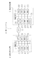
以下、本発明の実施の形態に係る通信システムについて図面に基づいて説明する。図1に示すように、本通信システムAは、一人暮らしの老人などの被監視者側に設置される被監視側装置Bと、監視者側に設置される監視側装置Cとからなり、双方の装置、被監視側装置B、監視側装置CはPSTN(公衆交換電話網)11を通じて後述する所定の通信を行う。なお、被監視側装置Bおよび監視側装置Cは、いずれも電話機やファクシミリ通信機で実現される。
【0009】
被監視側装置Bは、制御部(MPU)1、ROM(リードオンリーメモリ)2、RAM(ランダムアクセスメモリ)3、表示部4、操作部5、スピーカ6、時計部7、モデム8およびNCU(ネットワークコントロールユニット)9を備えている。そして、各部1乃至9は通信可能にバス10によって接続されている。
【0010】
制御部1は、所定のプログラムに従って、被監視側装置Bを構成する各部を制御する。
【0011】
ROM2は、制御部1が被監視側装置Bの各部の動作を制御するための各種プログラムを記憶している。
【0012】
RAM3は、監視側装置Cの電話番号、監視側装置Cへ発呼を行う時刻、制御部1によって設定された使用履歴フラグ等を記憶する。
【0013】
表示部4は、液晶表示装置等からなり、被監視側装置Bの状態に関する情報および各種操作画面を表示する。
【0014】
操作部5は、電話番号等の入力を行うテンキー、表示部4内の反転表示の移動などを行うための矢印キー等を具備し、各種操作はこの操作部5から行われる。また、被監視者が行う操作は、この操作部5から行うダイヤル操作、留守番電話機能の操作、受話器をあげる操作等である。
【0015】
スピーカ6は、外部からPSTN11を介して呼出信号を受信したときに、その呼出信号に応じて被監視者を呼び出すためにベルを鳴動させ、時計部7は、制御部1の要求に応じて現在時刻を送出する。
【0016】
モデム8は、送受信データの変復調、具体的には送信データを音声帯域信号に変調してNCU9を介してPSTN11に送出する一方、PSTN11からNCU9を介して受信した音声帯域信号をディジタル信号に復調する。
【0017】
NCU9は、電話回線を制御して電話をかけたり、切ったりする回線網制御装置であり、PSTN11に接続されている。
【0018】
一方、監視側装置Cは制御部21、ROM22、RAM23、表示部24、操作部25、スピーカ26、時計部27、記録部28、モデム29およびNCU30を備えている。また、各部21乃至30はバス31によって通信可能に接続されている。
【0019】
制御部21は所定のプログラムに従って、監視側装置Cを構成する各部を制御する。
【0020】
ROM22は、制御部21が監視側装置Cの各部の動作を制御するための各種プログラムを記憶している。
【0021】
RAM23は、電話番号、被監視側装置Bの使用の有無に応じて監視者に被監視者の安否を通知するための安否メッセージの音声データ、印字データおよび表示データを記憶している。
【0022】
表示部24は、液晶表示装置等からなり、監視側装置Cの状態に関する情報、各種操作画面、制御部21からの制御命令に基づきRAM23に記憶されている安否メッセージ等を表示する。
【0023】
操作部25は、電話番号等の入力を行うテンキー、表示部24内の反転表示の移動などを行うための矢印キー等を具備し、制御部21の判断に基づいて監視者に通知する安否メッセージを表示部24、スピーカ26、記録部28の何れに出力させるかの設定等はこの操作部25から行われる。
【0024】
スピーカ26は、通常、PSTN11を介して交換機から送られてくる呼出信号に応じて監視者を呼び出すためにベルを鳴動させる。また、スピーカ26は制御部21の命令に基づいてRAM23に記憶されている安否メッセージを音声出力する。
【0025】
記録部28は、電子写真方式、インクジェット方式、インクリボン方式、感熱方式等の適当な方式のものからなり、制御部21の命令に基づいてRAM23に記憶されている安否メッセージを記録紙上に印刷する。
【0026】
時計部27、モデム29、NCU30は、被監視側装置Bの時計部7、モデム8、NCU9とそれぞれ同様のものである。
【0027】
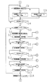
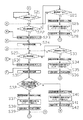
以下、被監視側装置Bと監視側装置Cの間で行われる通信シーケンスについて図2および図3のフローチャートに基づき説明する。なお、後述する設定時刻は、T1、T2、T3、T4、T5の順に経過するように設定されており、また、初期状態においては使用履歴フラグは「0」になっている。
【0028】
被監視側装置Bにおいて、被監視者が受話器をあげる操作、ダイヤル操作、留守番電話機能の操作など被監視側装置Bを使用したと認められる操作が行われた場合、被監視者が被監視側装置Bを使用したことを示す検出信号が制御部1に送出され、制御部1は被監視側装置Bの使用があったと判断し(S1)、被監視者が被監視側装置Bを使用したか否かを示す使用履歴フラグを「1」に設定して保持する(S2)。一方、被監視側装置Bが使用されなかった場合、制御部1は使用履歴フラグを「0」のまま保持する(S3)。これらの被監視者が被監視側装置Bを使用したか否かの判断と使用履歴フラグの設定は、設定時刻T2まで繰り返し行われる。
【0029】
続いて、設定時刻T2経過後(S4)、制御部1はRAM3に記憶されている使用履歴フラグを読み出し、使用履歴フラグが「1」に設定されている場合(S5)、RAM3に登録されている監視側装置Cの電話番号を読み出し(S6)、監視側装置Cに発呼を開始する(S7)。
【0030】
被監視側装置Bからのダイヤル選択信号を受信した交換機は、そのダイヤル選択信号を基に監視側装置Cへ接続動作を行う。すなわち、着信側である監視側装置Cが空き状態の場合に、監視側装置Cに対し事業用電気通信設備規則第31条第2号で規定されている1秒間のON信号を2秒間の休止期間をおいて断続する呼出信号(IR)を送出するとともに、発信元である被監視側装置Bに対して監視側装置Cを呼び出していることを知らせる事業用電気通信設備規則第33条で規定されている1秒間のON信号を2秒間の休止期間をおいて断続する呼出音(RBT)を送出する。
【0031】
監視側装置Cは、設定時刻T1経過後(S21)、交換機から送られてくる呼出信号を受信すると(S22)、監視者が誤って回線を繋いでしまうのを防ぐために音声や表示による呼び出し等の着信通知処理動作は行わずに、受信した呼出信号の信号断続回数を呼出信号数としてカウントする(S23)。
【0032】
これに対し、被監視側装置Bは交換機から送られてくる呼出音の信号断続回数を呼出音数としてカウントし、その呼出音数がRAM3に登録されている呼出音数に達すると(S8)、発呼を停止する(S9)。
【0033】
被監視側装置Bの発呼停止を受けて、監視側装置Cは、被監視側装置Bが発呼を開始してから停止するまでにカウントした呼出信号数を1回目の呼出信号数としてRAM23に記憶させる(S24)。
【0034】
一方、被監視側装置BがS5において、使用履歴フラグが「0」であると判断した場合、制御部1は監視側装置Cに対して発呼を行わない。よって、監視側装置Cは、設定時刻T3になっても呼出信号を受信することはないので(S22、S25)、設定時刻T3になった時点で、制御部21は被監視者が被監視側装置Bを使用しなかったものと判断し(S26)、例えば「被監視者の無事を確認できませんでした」等の注意を促す安否メッセージをRAM23から読み出して(S27)、記録部28より印字出力し、表示部24に表示させ、あるいはスピーカ26によって報知させる(S28)。
【0035】
被監視側装置Bは、S7乃至S9の監視側装置Cに対する回線を繋ぐまでの通信シーケンスを行った後、設定時刻T4経過後に(S10)、監視側装置Cに対して再度発呼を開始する(S11)。
【0036】
これに対し監視側装置Cは、交換機から送られてくる呼出信号を受信すると(S29)、S23の場合と同様に音声や表示による呼び出しを行わず、受信した呼出信号を2回目の呼出信号としてカウントする(S30)。
【0037】
被監視側装置Bは、S8の場合と同様にその呼出音数がRAM3に登録されている2回目の呼出音数に達すると(S12)、発呼を停止する(S13)。また、被監視側装置Bはこの発呼停止後、使用履歴フラグを「0」に戻し(S14)、再度被監視者による使用の有無を監視する。
【0038】
被監視側装置Bの発呼停止を受けて、監視側装置Cは、被監視側装置Bが2回目の発呼を開始してから停止するまでにカウントした呼出信号数を2回目の呼出信号数としてRAM23に記憶させる(S31)。
【0039】
一方、S22で受信した呼出信号が第三者からのものであり、S29において呼出信号を受信しなかった場合、監視側装置Cは設定時刻T5経過後に(S33)、被監視者が被監視側装置Bを使用しなかったものと判断し(S34)、S27およびS28と同様にして監視者に対し注意を促すための安否メッセージを通知する(S35、S36)。
【0040】
S31において2回目の呼出信号数を記憶した後、S24において記憶した1回目の呼出信号数とS31において記憶した2回目の呼出信号数とがいずれもRAM23に予め登録されている呼出信号数(通信シーケンス)と一致した場合(S32)、制御部21は1回目の呼出信号および2回目の呼出信号はともに被監視側装置Bの発呼によるものであり、被監視者は被監視側装置Bを使用したと判断し(S37)、RAM23に記憶されている被監視者が無事であることを告げるための安否メッセージ、例えば、「被監視者の無事を確認できました」等を読み出し(S38)、記録部28に印字出力し、表示部24に表示させ、あるいはスピーカ26に報知させる(S39)。
【0041】
一方、S32において1回目の呼出信号数と2回目の呼出信号数がRAM23に予め登録されている呼出信号数とどちらか一方でも一致しない場合、制御部21は被監視者が被監視側装置Bを使用しなかったものと判断し(S40)、S27およびS28と同様に監視者に対し注意を促す旨の安否メッセージを通知する(S41、S42)。
【0042】
なお、被監視側装置Bは2回の通信シーケンスを実行し、監視側装置Cはその2回の通信シーケンスが予め登録されている通信シーケンスと一致するかどうか判断しているが、これは、被監視側装置Bが監視側装置Cに対し発呼を行うのと同じ時刻に、第三者から発呼が行われた場合や、その呼出信号数が偶然にも予め登録されている呼出信号数と一致してしまった場合に第三者からの呼出信号を誤って被監視側装置Bからの呼出信号と判断してしまう恐れがあるからであり、2回の通信シーケンスがともにRAM23に登録されている通信シーケンスとそれぞれ一致するかどうかを判断することにより、第三者からの呼出信号数が予め登録されている呼出信号数と偶然一致する確率を減少させることを図っている。
【0043】
以上説明したように、本実施形態の通信システムAによれば、被監視側装置Bが行なった回線を繋ぐまでの通信シーケンスと、監視側装置Cに予め登録された通信シーケンスの一致不一致により被監視者が被監視側装置Bを使用したか否かを監視側装置Cに伝えるので、監視者は通信料金をかけることなく被監視者の安否を確認することができる。
【0044】
【発明の効果】
請求項1記載の通信システムによれば、被監視側装置は公衆交換電話網を介して回線を繋ぐことなく、監視側装置に被監視者が被監視側装置を使用したことを伝えることができるので、監視者は、通信料金をかけることなく一人暮らしの老人の無事を確認することができる。
【0045】
請求項2記載の通信システムによれば、被監視側装置は公衆交換電話網を介して回線を繋ぐことなく、監視側装置に被監視者が被監視側装置を使用しなかったことを伝えることができるので、監視者は、通信料金をかけることなく一人暮らしの老人の異変を察知することができる。
【0046】
請求項3記載の通信システムによれば、音声や表示による呼出動作を行わないので、監視者が誤って回線を繋いでしまうことを防止できる。
【図面の簡単な説明】
【図1】本発明の実施の形態に係る通信システムの制御構成を示す図である。
【図2】被監視側装置における制御手順を示すフローチャートである。
【図3】監視側装置における制御手順を示すフローチャートである。
【符号の説明】
A 通信システム
B 被監視側装置
C 監視側装置
1、21 制御部(MPU)
3、23 RAM
9、30 NCU(ネットワークコントロールユニット)
11 PSTN
28 記録部[0001]
TECHNICAL FIELD OF THE INVENTION
The present invention relates to a communication system using a public communication line, and more specifically, information on the use of home appliances by an elderly person living alone is transmitted to a monitoring device via a public communication line to monitor the safety of the elderly person. The present invention relates to a communication system.
[0002]
[Prior art]
In recent years, as the number of elderly people living alone has increased, as a method of confirming the safety of the elderly, information on the use of household electrical appliances by the elderly, as disclosed in Japanese Patent Application Laid-Open No. H11-120466, has been published. There is a method in which the information is transmitted to a monitoring device via a network, and the monitor checks the safety of the elderly person from the information.
[0003]
[Problems to be solved by the invention]
However, this method has a problem that a telephone charge is required because information is transmitted through a public switched telephone network in a public communication line.
[0004]
The present invention has been made in view of the above problems, and an object of the present invention is to provide a communication system capable of monitoring the safety of an elderly living alone without incurring a communication fee.
[0005]
[Means for Solving the Problems]
To achieve the above object, a communication system according to claim 1, wherein a monitored device whose usage is monitored and a monitoring device that monitors the usage of the monitored device via a public communication line. A communication system including the device, wherein the monitored device detects and stores that its own device has been used for a predetermined period, and after the predetermined period elapses, the monitored device The monitoring side apparatus executes a predetermined communication sequence until the line is connected, and the monitoring side apparatus determines that the communication sequence formed by the signal received until the line is connected matches the communication sequence registered in the apparatus in advance. Output that the monitored device has been used.
[0006]
The communication system according to claim 2, wherein the monitoring-side device is configured such that when the communication sequence formed by a signal received before the line is connected does not match the pre-registered communication sequence, the monitored-side device It is characterized by outputting that it was not used.
[0007]
4. The communication system according to claim 3, wherein the predetermined communication sequence includes an operation in which the monitored device calls the monitoring device and the monitoring device receives a call signal. The apparatus is characterized in that it does not perform an incoming call notification processing operation when receiving a call signal.
[0008]
BEST MODE FOR CARRYING OUT THE INVENTION
Hereinafter, a communication system according to an embodiment of the present invention will be described with reference to the drawings. As shown in FIG. 1, the communication system A includes a monitored device B installed on a monitored person side such as an elderly person living alone and a monitored device C installed on a monitored person side. The device, the monitored device B, and the monitoring device C perform predetermined communication described later through a PSTN (Public Switched Telephone Network) 11. Each of the monitored device B and the monitoring device C is realized by a telephone or a facsimile communication device.
[0009]
The monitored device B includes a control unit (MPU) 1, a ROM (read only memory) 2, a RAM (random access memory) 3, a display unit 4, an operation unit 5, a speaker 6, a clock unit 7, a modem 8, and an NCU ( A network control unit) 9. The units 1 to 9 are communicably connected by a bus 10.
[0010]
The control unit 1 controls each unit configuring the monitored device B according to a predetermined program.
[0011]
The ROM 2 stores various programs for the control unit 1 to control the operation of each unit of the monitored device B.
[0012]
The RAM 3 stores the telephone number of the monitoring device C, the time of making a call to the monitoring device C, the usage history flag set by the control unit 1, and the like.
[0013]
The display unit 4 includes a liquid crystal display device or the like, and displays information relating to the state of the monitored device B and various operation screens.
[0014]
The operation unit 5 includes ten keys for inputting a telephone number and the like, arrow keys for moving the reverse display in the display unit 4, and the like, and various operations are performed from the operation unit 5. The operations performed by the monitored person include a dial operation performed from the operation unit 5, an operation of the answering machine function, an operation of raising the handset, and the like.
[0015]
When the speaker 6 receives a calling signal from the outside via the PSTN 11, the speaker 6 rings a bell to call the monitored person in response to the calling signal, and the clock unit 7 responds to the request of the control unit 1. Send the time.
[0016]
The modem 8 modulates and demodulates the transmission / reception data, specifically, modulates the transmission data into a voice band signal and sends it to the PSTN 11 via the NCU 9, while demodulating the voice band signal received from the PSTN 11 via the NCU 9 into a digital signal. .
[0017]
The NCU 9 is a network controller for controlling a telephone line to make or disconnect a telephone call, and is connected to the PSTN 11.
[0018]
On the other hand, the monitoring device C includes a control unit 21, a ROM 22, a RAM 23, a display unit 24, an operation unit 25, a speaker 26, a clock unit 27, a recording unit 28, a modem 29, and an NCU 30. The units 21 to 30 are communicably connected by a bus 31.
[0019]
The control unit 21 controls each unit configuring the monitoring apparatus C according to a predetermined program.
[0020]
The ROM 22 stores various programs for the control unit 21 to control the operation of each unit of the monitoring apparatus C.
[0021]
The RAM 23 stores voice data, print data, and display data of a safety message for notifying the monitor of the safety of the monitored person according to the telephone number and whether or not the monitored device B is used.
[0022]
The display unit 24 is composed of a liquid crystal display device or the like, and displays information relating to the state of the monitoring-side device C, various operation screens, safety messages stored in the RAM 23 based on control commands from the control unit 21, and the like.
[0023]
The operation unit 25 includes a numeric keypad for inputting a telephone number and the like, arrow keys for moving a reverse display in the display unit 24, and the like, and a safety message to notify a supervisor based on a determination of the control unit 21. Of the display unit 24, the speaker 26, and the recording unit 28 is set from the operation unit 25.
[0024]
The speaker 26 normally rings a bell to call a supervisor in response to a calling signal sent from the exchange via the PSTN 11. Further, the speaker 26 outputs a safety message stored in the RAM 23 by voice based on a command from the control unit 21.
[0025]
The recording unit 28 is formed of an appropriate system such as an electrophotographic system, an inkjet system, an ink ribbon system, and a thermal system, and prints a safety message stored in the RAM 23 on a recording paper based on a command from the control unit 21. .
[0026]
The clock unit 27, the modem 29, and the NCU 30 are the same as the clock unit 7, the modem 8, and the NCU 9 of the monitored device B, respectively.
[0027]
Hereinafter, a communication sequence performed between the monitored device B and the monitoring device C will be described with reference to the flowcharts of FIGS. 2 and 3. The set time described later is set so as to elapse in the order of T1, T2, T3, T4, and T5, and the use history flag is "0" in an initial state.
[0028]
When the monitored device B performs an operation that is recognized as having used the monitored device B, such as an operation of lifting the handset, dialing, or operating an answering machine function, the monitored device is switched to the monitored device. A detection signal indicating that the device B has been used is sent to the control unit 1, and the control unit 1 determines that the monitored device B has been used (S1), and the monitored person has used the monitored device B. The usage history flag indicating whether or not this is set to “1” is held (S2). On the other hand, when the monitored device B is not used, the control unit 1 keeps the use history flag at “0” (S3). The determination as to whether the monitored person has used the monitored device B and the setting of the usage history flag are repeatedly performed until the set time T2.
[0029]
Subsequently, after a lapse of the set time T2 (S4), the control unit 1 reads the use history flag stored in the RAM 3 and, if the use history flag is set to "1" (S5), the control unit 1 registers the use history flag in the RAM 3 The telephone number of the monitoring device C is read out (S6), and a call to the monitoring device C is started (S7).
[0030]
The exchange that has received the dial selection signal from the monitored device B performs a connection operation to the monitoring device C based on the dial selection signal. That is, when the monitoring-side device C, which is the receiving side, is in an idle state, the monitoring-side device C is given a one-second ON signal specified in Article 31-2 of the Business Telecommunications Equipment Regulations for a two-second pause. A calling signal (IR) that is intermittently transmitted after a certain period of time, and is specified in Article 33 of the Business Telecommunications Equipment Regulations for notifying the monitored device B, which is the transmission source, that the monitoring device C is being called. An intermittent ringing tone (RBT) is transmitted after a 1 second ON signal with a 2 second pause.
[0031]
After the set time T1 has elapsed (S21), the monitoring device C receives a call signal sent from the exchange (S22), and in order to prevent the monitor from erroneously connecting the line, calls are made by voice or display. The incoming call notification processing operation is not performed, and the number of interrupted signals of the received call signal is counted as the number of call signals (S23).
[0032]
On the other hand, the monitored device B counts the number of intermittent ringing signals transmitted from the exchange as the number of ringing tones, and when the number of ringing tones reaches the number of ringing tones registered in the RAM 3 (S8). Then, the calling is stopped (S9).
[0033]
In response to the stop of the call from the monitored device B, the monitoring device C sets the number of call signals counted from when the monitored device B starts calling until the monitored device B stops calling as the first call signal number to the RAM 23. (S24).
[0034]
On the other hand, when the monitored device B determines in S5 that the use history flag is “0”, the control unit 1 does not call the monitoring device C. Therefore, the monitoring device C does not receive the call signal even at the set time T3 (S22, S25), and at the time of the set time T3, the control unit 21 sets the monitored person to the monitored side. It is determined that the device B has not been used (S26), and a safety message, such as "Could not confirm the safety of the monitored person", is read from the RAM 23 (S27) and printed out from the recording unit 28. Then, it is displayed on the display unit 24 or notified by the speaker 26 (S28).
[0035]
The monitored device B performs the communication sequence from S7 to S9 until the line is connected to the monitoring device C, and after the set time T4 elapses (S10), the monitored device B starts calling again to the monitoring device C. (S11).
[0036]
On the other hand, when the monitoring apparatus C receives the call signal sent from the exchange (S29), it does not make a call by voice or display as in S23, and uses the received call signal as the second call signal. The counting is performed (S30).
[0037]
As in the case of S8, when the number of ring tones reaches the second number of ring tones registered in the RAM 3 (S12), the monitored device B stops calling (S13). After stopping the call, the monitored device B returns the use history flag to "0" (S14), and monitors whether or not the monitored person has used it again.
[0038]
In response to the stoppage of the call from the monitored device B, the monitoring device C counts the number of call signals counted from when the monitored device B starts the second call until the call is stopped, to the second call signal. The number is stored in the RAM 23 (S31).
[0039]
On the other hand, if the paging signal received in S22 is from a third party and the paging signal is not received in S29, the monitoring side device C sets the monitored person to the monitored side after the elapse of the set time T5 (S33). It is determined that the device B has not been used (S34), and a safety message for calling attention to the monitor is notified in the same manner as in S27 and S28 (S35, S36).
[0040]
After storing the second call signal number in S31, the first call signal number stored in S24 and the second call signal number stored in S31 are both registered in the RAM 23 (communication number). (S32), the control unit 21 determines that the first call signal and the second call signal are both originating from the monitored device B, and the monitored person switches the monitored device B to the monitored device B. It is determined that the monitored person has been used (S37), and a safety message stored in the RAM 23 for notifying that the monitored person is safe, for example, "confirmed that the monitored person is safe" or the like is read (S38). Then, it is printed out on the recording unit 28 and displayed on the display unit 24 or notified by the speaker 26 (S39).
[0041]
On the other hand, if the number of first call signals and the number of second call signals do not match either of the numbers of call signals registered in the RAM 23 in S32, the control unit 21 determines that the monitored person is the monitored device B Is determined not to have been used (S40), and a safety message notifying the observer is notified as in S27 and S28 (S41, S42).
[0042]
Note that the monitored device B executes two communication sequences, and the monitoring device C determines whether the two communication sequences match a pre-registered communication sequence. At the same time when the monitored device B makes a call to the monitoring device C, a call is made by a third party, or a call signal whose number of call signals is accidentally registered in advance. If the numbers match, the call signal from a third party may be erroneously determined to be a call signal from the monitored device B, and both communication sequences are registered in the RAM 23. By judging whether or not each of the communication sequences matches the communication sequence, the probability that the number of call signals from a third party coincides with the number of call signals registered in advance is reduced.
[0043]
As described above, according to the communication system A of the present embodiment, the communication sequence up to the connection of the line performed by the monitored device B and the communication sequence registered in the monitoring device C are inconsistent with each other. Since the monitor notifies the monitor-side device C whether or not the monitor-side device B has been used, the monitor- er can confirm the safety of the monitor-side person without incurring a communication fee.
[0044]
【The invention's effect】
According to the communication system of the first aspect, the monitored device can notify the monitoring device that the monitored person has used the monitored device without connecting the line via the public switched telephone network. Therefore, the monitor can confirm the safety of the elderly living alone without incurring a communication fee.
[0045]
According to the communication system of the second aspect, the monitored device notifies the monitoring device that the monitored person did not use the monitored device without connecting the line via the public switched telephone network. Thus, the observer can detect an unusual situation of an elderly living alone without paying a communication fee.
[0046]
According to the communication system of the third aspect, since a calling operation by voice or display is not performed, it is possible to prevent a monitor from connecting to a line by mistake.
[Brief description of the drawings]
FIG. 1 is a diagram showing a control configuration of a communication system according to an embodiment of the present invention.
FIG. 2 is a flowchart illustrating a control procedure in the monitored device.
FIG. 3 is a flowchart illustrating a control procedure in the monitoring apparatus.
[Explanation of symbols]
A Communication System B Monitored Device C Monitoring Device 1, 21 Control Unit (MPU)
3,23 RAM
9, 30 NCU (network control unit)
11 PSTN
28 Recorder